

Page 1

Owner's Guide
FLOOR BOXES
85.2611.00
®
Page 2
Warranty Information
N/A
N/A
For service information contact your local authorized A-dec dealer.
Check with local codes and A.D.A. (Americans with Disabilities Act)
Requirements for Installation of this product.
Serial Number
Model Number
Date Purchased
Date of
Service
Model/Description of Service
Technician's
Initials
Page 3
Floor Boxes
Printed in USA • Copyright © 1999 • All Rights Reserved
A-dec warrants its products and A-dec/W&H Synea
handpieces against defects in material or workmanship
for one year from time of delivery. All other handpiece
instrumentation has a warranty period of six months.
A-dec’s sole obligation under the warranty is to provide
parts for the repair, or at its option, to provide the
replacement product (excluding labor). The buyer shall
have no other remedy. (All special, incidental, and
coincidental damages are excluded.) Written notice of
breach of warranty must be given to A-dec within the
warranty period. The warranty does not cover damage
resulting from improper installation or maintenance,
accident or misuse.The warranty does not cover damage resulting from the use of cleaning, disinfecting or
sterilization chemicals and processes. The warranty also
does not cover light bulbs. Failure to follow instructions
provided in A-dec’s Operation and Maintenance
Instructions (Owner’s Guide) may void the warranty.
NO OTHER WARRANTIES AS TO
MERCHANTABILITY OR OTHERWISE ARE MADE.
All product names used in this document are trademarks or
registered trademarks of their respective holders.
®
Page 4

Page 5

Service information and warranty information are located on the inside front cover
and front page.
About Your Floor Box .......................................... 2
Floor Box Controls and Functions ...................... 3
Air and Water Manual Shut-off Valves ........ 5
Air-actuated Air and Water
Shut-off Valves ........................................ 5
Air and Water Filters ..................................... 5
Air and Water Pressure Pre-Regulators ........ 5
Power Supply ................................................ 6
Gravity Drain Outlet and Air Vent ............... 6
Vacuum Outlet .............................................. 7
Care Instructions ................................................. 8
(Refer also to your A-dec Equipment Asepsis
Owner’s Guide,Publication No. 85.0696.00.)
System Air and Water
Pressure Adjustments ................................... 8
Filter Maintenance ........................................... 10
Air and Water Filter Elements .................... 10
Checking for a Clogged Air Filter ......... 10
Checking for a Clogged Water Filter .... 10
Inspecting the Filters ............................. 11
Water Screen ............................................... 12
Maintenance ......................................................13
Adjustments and Specifications.........................13
Identification of Symbols ................................. 14
Classification of Equipment(EN 60601-1) ....... 14
CONTENTS
Floor Boxes
Page 6
Your Cascade, recessed, or stainless steel floor box
(see Figure 1) is mounted over the utilities on the
floor or wall of the operatory. Located in the floor
box are the air and water manual shutoff valves,
filters, and pressure pre-regulators. You will find
vacuum or gravity drains as well as electrical outlets.
2
Floor Boxes
OPERATION
Figure 1. Floor Boxes
LARGE STAINLESS
STEEL
(14.5" X 17")
CASCADE
(14.5" X 17")
RECESSED
(14.5" X 18")
MEDIUM STAINLESS
STEEL
(9" X 14")
About Your Floor Box
Page 7

3
Floor Boxes
The stainless steel floor box covers lift off for
access to the utilities and optional power supplies
and/or water heater.
To remove the cover from your Cascade Floor
Box, slide the cover forward a little and lift.
The recessed floor box cover is held in place
by four screws. Removing the screws will allow
you to lift the cover.
Floor Box Controls and Functions
MANUAL SHUT-OFF VALVES
WATER AIR
AIR ACTUATED
SHUTOFF VALVES
PRE-REGULATORS
FILTERS
WATER TEMPERATURE CONTROL
(TANK-TYPE WATER HEATER)
Figure 2. Cascade and Large Floor Boxes
NOTE
Do not use saline solution, mouth rinses, or any
chemical solutions not specified in this manual
in your municipal water supply. These may
damage the water system components and cause
the failure of your dental unit. If you need to use
such solutions, a water supply systemseparate
from your dental unit should be used. As a
general rule, water that is suitable for drinking is
suitable to use in your delivery system.
4
3
50
60
5
40
2
70
30
80
20
6
1
90
10
100
0
psi
7
0
2
4
3
50
60
5
40
2
70
30
80
20
6
1
90
10
100
0
psi
7
0
2
kg/cm
Page 8

4
Floor Boxes
AIR ACTUATED AIR SHUTOFF VALVE
AIR ACTUATED WATER SHUTOFF VALVE
AIR MANUAL SHUTOFF VALVE
WATER MANUAL SHUTOFF VALVE
AIR PRE-REGULATOR
WATER PRE-REGULATOR
AIR PRESSURE GAUGE
WATER PRESSURE GAUGE
AIR FILTER
WATER FILTER
WATER
TEMPERATURE
CONTROL
Figure 3. Medium Floor Box
AIR ACTUATED AIR
SHUTOFF VALVE
AIR ACTUATED WATER
SHUTOFF VALVE
AIR MANUAL
SHUTOFF VALVE
WATER MANUAL
SHUTOFF VALVE
PRE-REGULATOR
PRE-REGULATOR
AIR
PRESSURE
GAUGE
WATER
PRESSURE
GAUGE
AIR
FILTER
Figure 4. Recessed Floor Box
WATER
FILTER
Page 9

Shutoff Valves control the air and water to the
unit. To prevent leaks, these valves should remain
fully open (turned counterclockwise) except while
your unit is being serviced.
The Air-actuated Air and Water Shutoff Valves
automatically shut off air and water to the system
when the master on/off toggle is in the OFF position.
This safety feature prevents water damage in the
event the unit should develop a water leak while the
unit is unattended.
Filters prevent solids from entering the unit. The
procedures for checking and replacing the filters are
given on pages 10 and 11.
Pre-Regulators control the air and water
pressures in the unit. The procedure for adjusting
system pressure is given on page 8.
5
Floor Boxes
Air and Water Pressure Pre-Regulators
Air and Water Filters
Air-actuated Air and Water Shutoff Valves
Air and Water Manual Shutoff Valves
Page 10

Your system may include A-dec’s 17 watt power
supply or 300 watt power supply. No cleaning
or maintenance is required to maintain the
power supply.
If a problem arises with the power supply or an
A-dec electrical accessory to the power supply,
call your authorized A-dec dealer.
The Gravity Drain (a “T” fitting) (see Figure 6) is
connected to the office waste drainage system and
provides for the disposal of water and debris from
the unit.
6
Floor Boxes
Power Supply
300 Watt Power
Supply
17 Watt Power
Supply
Gravity Drain and Air Vent
Figure 6. Gravity Drain and Air Vent
TO THE OFFICE WASTE
DRAINAGE SYSTEM
AIR VENT
FLEXIBLE TUBE FROM
THE OPTIONAL GRAVITY
DRAIN CUSPIDOR
“T” FITTING
NOTE
The master on/off toggle switches the control
head, dental light, auxiliary cable, and the
indicator light on or off.
Page 11

The Air Vent (the open end of the “T” fitting)
prevents air being trapped in the office waste
drainage system. If the vent becomes obstructed,
waste water and debris may backup into the unit.
If A-dec’s optional circulating warm water
syringe is included with your unit, a water drip
tube will be positioned over the drain air vent. The
drip tube is the outlet for warm water supplied to
your syringe by the water heater. For more
information about your syringe, refer to your
Autoclavable Syringe Owner’s Guide, A-dec
Publication No. 85.0680.00.
If A-dec’s optional Radius,Cascade, or Decade
Cuspidor is included with your unit, a flexible tube
from the cuspidor will be connected to the gravity
drain. For information about the gravity drain
cuspidor, refer to the Cascade 7284 and Radius
7285 Cuspidor Owner’s Guide, A-dec Publication
No. 85.2609.00 or Decade 7283 Owner’s Guide,
A-dec Publication No. 85.0685.00.
The office central vacuum system outlet is
located in the floor box. A flexible tube connects
your vacuum instruments and optional Cascade
or Decade vacuum cuspidor to the outlet.
For information about your assistant’s vacuum
instruments, refer to your Assistant’s
Instrumentation Owner’s Guide, A-dec
Publication No. 85.2610.00.
For information about the optional Cascade
vacuum drain cuspidor, refer to theCascade 7284
and Radius 7285 Cuspidor Owner’s Guide, A-dec
Publication No. 85.2609.00.
For information about the optional Decade
vacuum drain cuspidor, refer to Decade 7283
Owner’s Guide, A-dec Publication No. 85.0685.00.
7
Floor Boxes
Vacuum Outlet
Page 12

For recommended asepsis instructions, refer to
your A-dec Equipment Asepsis Owner’s Guide,
A-dec Publication No. 85.0696.00.
The air and water pre-regulators are located in
the floor box. Before making any adjustments,
verify that the air compressor is turned on, and
that it maintains 80–100 psi pressure in the
tank. If it doesn't, refer to the compressor
instructions.
8
Floor Boxes
Care Instructions
System Air and Water Pressure
Adjustments
NOTE
When decreasing system air or water pressure,
you will not see the air or water pressure gauge
in the floor box change until you relieve
pressure from the system. Activate the syringe
for a few seconds, then check the gauge. Repeat
this process each time you make an adjustment
to decrease pressure.
Page 13

1. Be sure that the manual shutoff valves are
fully open (counterclockwise). Turn the
system on and check the pressure gauges in
the floor box (see Figures 7 and 8). Air
pressure should be 70–80 psi while water
pressure should be 35–40 psi.
9
Floor Boxes
Figure 7. Cascade and Large Floor Box
MANUAL SHUTOFF VALVES
WATER
PRESSURE
GAUGE
AIR
PRESSURE
GAUGE
Figure 8. Medium Floor Box
MANUAL SHUTOFF
VALVES
WATER
PRESSURE
GAUGE
AIR PRESSURE
GAUGE
WATER PREREGULATOR
KNOB
WATER PRE-REGULATOR
KNOB
AIR PREREGULATOR
KNOB
AIR PRE-REGULATOR KNOB
4
3
50
60
40
2
70
30
80
20
1
90
10
100
0
psi
0
2
kg/cm
4
3
50
60
5
6
7
5
40
2
70
30
80
20
6
1
90
10
100
0
psi
7
0
2
Page 14

2. While watching the gauges, operate the
syringe. If the system air pressure drops by
any more than 15 psi, or water pressure by
more than 10 psi, check for clogged filters.
3. If adjustment of either the air or water
pressure is required, turn the appropriate
pre-regulator knob clockwise to increase
pressure, or counterclockwise to decrease.
Air and water pass through separate filters before
entering the regulators. A filter must be replaced
when it becomes sufficiently clogged causing
restricted flow to the regulator.
Checking for a Clogged Air Filter
To check for a clogged air filter, flip the master
on-off toggle to the ON position and remove the
floor box cover. While watching the air pressure
gauge in the floor box (see Figures 7 and 8), press
the syringe air button. If the air pressure indicated
by the gauge drops by more than 15 psi, the filter
element is clogged and must be replaced.
Checking for a Clogged Water Filter
To check for a clogged water filter, flip the master
on-off toggle on the control head to the ON
position, then remove the floor box cover. Watch
the water gauge, press the syringe water button. If
the water pressure drops by more than 10 psi, the
water filter is clogged and must be replaced.
10
Floor Boxes
Air and Water Filter Elements
Filter Maintenance
Page 15

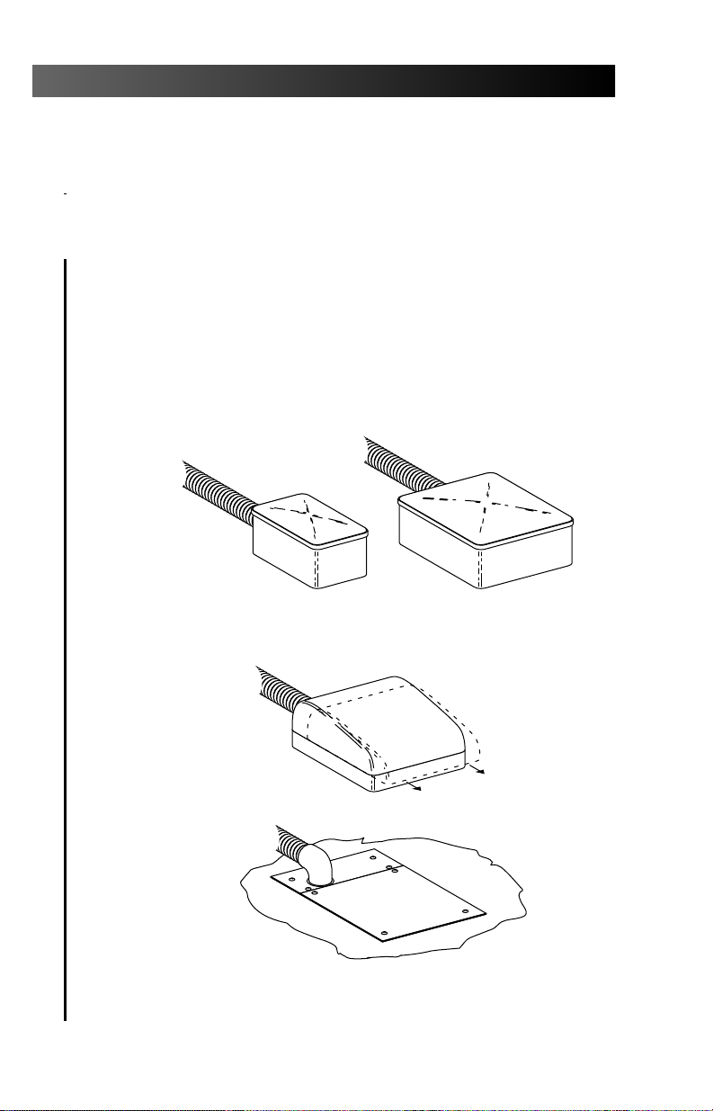
Inspecting the Filters
To inspect or replace a filter element, flip the
master on-off toggle to the OFF position, then close
the manual shutoff valves. Bleed the system of
air and water pressure by operating the syringe
buttons until air and water no longer flow. Using a
standard (flat-blade) screwdriver, remove the filter
housing from the air and/or water pre-regulators
assemblies (see Figure 9) and remove the filter.
If the filter is visibly clogged or discolored, you will
need to replace it.
When installing a new filter, notice that one end
of the filter has a beveled edge. Install the filter
with the beveled edge facing the manifold (see
Figure 9). The system will not work properly if the
filter is installed incorrectly.
11
Floor Boxes
Figure 9. Air or Water Filter Replacement
FILTER HOUSING
BEVELED EDGE
FILTER ELEMENT
O-RING
1
0
2
10
20
0
30
40
3
50
kg/cm
psi
100
60
2
4
90
7
70
80
5
6
Page 16

The manual water shutoff valve in your floor
box (see Figure 10) is equipped with a screen to
prevent debris from entering the system. You
should periodically check and replace this screen
to ensure unrestricted water flow to your unit.
To remove or replace a screen, first move the
master on/off toggle to the OFF position and close
the manual water shutoff valve.
Now, using a 5⁄8" or adjustable wrench, loosen
the compression nut on the manual water shutoff valve and pull the water regulator out of the
shutoff valve (see Figure 10). Remove the screen
and install the replacement screen.
Reposition the water regulator in the manual
shutoff valve outlet and tighten the compression
nut. Open the manual water shutoff valve and flip
the master toggle to the ON position. Check the
fittings for leaks.
12
Floor Boxes
Figure 10. Water Screen Replacement
WATER MANUAL
SHUTOFF VALVE
SCREEN
(water only)
COMPRESSION
NUT
Water Screen
1
0
2
10
20
0
30
40
3
50
kg/cm
psi
100
60
2
4
90
7
70
80
5
6
Page 17

Equipment Asepsis
Owner’s Guide ................................................ 85.0696.00
Filter Maintenance .................................................... page 10
System Air and Water
Pressure Adjustments .............................................. page 8
Autoclavable Syringe
Owner’sGuide....................................................85.0680.00
Minimum air, water, and vacuum service requirements
for proper unit operation:
Air: 2.50 cfm (70.80 l/min) at 80 psi (551 kPa).
Water: 1.50 gpm (5.68 l/min) at 40 psi (276 kPa).
Vacuum: 12 cfm (339.84 l/min) at 8 inches (27 kPa)
of mercury.
Specifications are subject to change without notice.
13
Floor Boxes
Maintenance
Adjustments and Specifications
Page 18

14
Floor Boxes
Recognized by Underwriters Laboratories Inc. ® with respect to
electric shock, fire and mechanical hazards only in accordance
with UL 2601-1. Recognized with respect to electric shock, fire,
mechanical and other specified hazards only in accordance with
CAN/CSA C22.2, No. 601.1.
UL listed to US (UL 544) and Canadian (CAN/CSA C22.2, No.
125) safety standards.
Classified by Underwriters Laboratories Inc. ® with respect to
electric shock, fire and mechanical hazards only in accordance
with UL 2601-1. Classified with respect to electric shock, fire,
mechanical and other specified hazards only in accordance with
CAN/CSA C22.2, No. 601.1.
Conforms to European Directives
(refer to Declaration Statement)
Protective earth (ground).
Functional earth (ground).
Attention, consult accompanying documents.
TYPE B APPLIED PART.
CLASS II EQUIPMENT.
Type of shock protection:
CLASS I EQUIPMENT
(Dental Chairs, Dental Lights, & Power Supplies)
CLASS II EQUIPMENT
(Chair, Wall, & Cart Mounted Delivery Systems)
Degree of shock protection:
TYPE B APPLIED PART (All products)
Degree of protection against water ingress:
ORDINARY EQUIPMENT (All products)
Mode of operation
CONTINUOUS OPERATION
(All models except Dental Chairs)
Mode of operation
CONTINUOUS OPERATION
WITH INTERMITTENT LOADING (Dental Chairs)
Identification of Symbols
Classification of Equipment (EN 60601-1)
®
LISTED
!
Page 19

Page 20

85.2611.00
1999-11 Rev H
(01649)
Printed in USA.
Copyright © 1999,
All Rights Reserved.
Made with 50% waste paper
2601 Crestview Drive
Newberg, Oregon 97132 U.S.A.
Telephone 1-800-547-1883
(503) 538-7478
Fax (503) 538-0276
®
Designated Representative’s Address:
A-dec Dental U.K., Ltd.
Austin House
11 Liberty Way
Attleborough Fields,
Nuneaton, Warwickshire,
England CV11 6RZ
Telephone: 00 44 24 7635 0901
Fax: 00 44 24 7634 5106
Designated Representative’s Address:
A-dec Australia
41-43 Bowden Street
Alexandria, N.S.W. 2015, Australia
Telephone: (61) 1.800.225010
 Loading...