

Page 1
2601
CRESTVIEW
INSTRUCTION
MANUAL
DRIVE + POST
OFFICE
BOX
111 « NEWBERG,
OREGON
97132
USA * TELEPHONE
503/538-7478
#4
Page 2
“aídec
Operation
and
Maintenance
Instructions
Pac
Model
|
(portable)
3420
Page 3
Wa
How
this
Section
rranty
to
Use
Manual
1
A-dec™
workmanship
warranty
product
incidental,
Written
The
accident
cleaning,
cover
(operation
A-dec
of
ders
manufacturing
warranty.
No
This
Your
maintenance.
questions
mation.
Set-up
warrants
is
(excluding
and
notice
warranty
or
disinfecting
light
bulbs.
and
warrants
purchase
already
other
warranties
manual
manual
and
to
misuse. The
of
should
all
products
for
one
year
provide
coincidental
of
does
maintenance
the
in
the
related
describes
is
Each
repacking
parts
labor).
breach
not
or
Failure
A-dec
dental
chair
field.
irregularities.
as
divided
section
help
cover
in
this
catalog
from
time
of
for
the
repair,
The
buyer
shall
damages
of
warranty
damage
warranty
sterilization
to
follow
instructions)
chair
or
the
The
warranty
to
merchantability
your
into
addresses
you
determine
The
How
or
must
does
chemicals
instructions
cylinders,
cylinder.
Stool
PAC I Portable
three
sections:
unit
do I repack
storage?
against
delivery.
or
at
its
have
are
excluded.
be
given
resulting
not
This
covers
just
from
cover
and
provided
may
void
both
warranty
chair
cylinders
or
otherwise
Delivery
Set-up
specific
which
arrived,
м
defects
A-dec’s
option,
no
other
to
improper
damage
processes.
the
lift
cylinders
are
information,
section
how
the
Field
in
sole
to
remedy.
A-dec
resulting
in
the
warranty.
and
tilt,
is
retroactive
A-dec
covered
are
made.
System,
and
repacking,
to
check
do I set
unit
material
obligation
provide
within
installation
The
A-dec
for
under
and
for
or
the
All
special,
the
from
warranty
Owner’s
ten
years
to
A-dec
finds
A-dec’s
|
,
Model
operation,
the
when
it
up?
transportation
under
the
replacement
warranty
or
the
to
3420
following
you
period.
maintenance,
use
of
also
does
Guide
from
the
chair
cylin-
have
one-year
and
list
need
not
date
of
infor-
wa
e
ワー
F
レレ
>
T
sa
ği
pa
J
Section
Section
2
3
Operation
Maintenance
We
understand
anywhere.
comprehensive.
contact
For
your
that
you
this
reason,
If
you
have
authorized
A-dec
How
do I operate
What
How
do I make
What
How
do I clean
How
does
What
Something
may
be
we
have
questions
dealer.
do
the
do
the
the
are
the
using
made
it?
controls
routine
accessories
it?
unit
work?
major
is
wrong,
this
after
components?
how
portable
the
Maintenance
reading
do?
adjustments?
do?
dental
the
|
can I fix
delivery
section
appropriate
it?
system
quite
section(s),
virtually
Ja
m.
e”
一
Æ
a
αλ
する
Page 4
Contents
Setup
Institutional
Field
All
Operation
About
Control
Instructions
| |
Unit:
AssembletheU-fame......................................
Mount
Assemble t e
Mount
Place
Install
Install
Install
InstalltheTrayHolder
Connect
PAC I Field
Testing
Repacking
the
Institutional
jn
“
sos. e 3
Tripo
the
Field
Pac I Portable
the
Han
and
Syringe
the
the
Optional
and
Optional
Your
PUNCHONS
Your
In
Self-Contained
Steril-Vac
the
Supply
Repair
Pac I Unit
the
Pac I Field
PAC
Puis,
Unit
Control
店
Lee
Unit
Control
Units:
othe 나 lde;
the
Air
Tool
0...
eee»
Ho
STB
Water
ie
Saliva
Kit
Ejector
.....................................
Air
Tubing
Kit
.........
иене
Unit..................... 5 General
Head
resezione
Bottle
.................... 4 Care
iii
een
1
Head
....
1
1
1
................ 2 How
3
ーー
.......... 3 Steril-Vac
(ASE)
ss
3
3
........ 3 Cleaning
4
‚.
5
5
6
7
Pre-Cleaning
sterilizatio
H
andpiece
H 때 Often
Flushing
Self-Contained
How
ICX
Water
ICX
Water
Operating
Oil
Collector
İnstructions
Maintenance
Farts
Cleaning
Tool
How
Your
Schematic
es
10
...................................
Tubing
the
it
Works
to
Choose
Your
Servicelnformation.............................
Imspection
Internal
and
Repair
PAC 1 Works
Diagram
Flush
Shel d ;
Handpiece
Water
Treatment
Treatment
Treatment
Your
Steril-Vac
Steril-Vac
.........................
eee
Parts
Kits
ーー
|
System........................
Flush?
System
Tablet.
Protocol
ϱϱ”ϱ””ϱ-
т
Tubings
M
............
Di.
.............
Water...
............................
........................
リー
Le
ОИ
リー
|
ος
10
11
11
11
11
11
12
12
12
13
13
‚
.
13
14
14
15
15
15
16
17
18
O
Han
Drive
“Coolant
Coolant
Air
Pressure
System
Drive
Foot
O
R
poa
outine A justments
an
Han
Handpiece
A-dec
Autoclavable
Syringe
Disconnecting
A-dec
Changing
SyringeandlipAsepsis...................................
Oise
piece
Selector
Air
Pressure
Air
Flow
Water
GAUBES
AirPressureGâuge
ーーーーーーーー
Control
Control...
Flow
Controls
„<
eee
............................
AirPressureGauge.................................
Control
ory
10081
一
μα
Air
ώρας
piece
Autoclava
Flow
Syringe
ipBlowerButton
Lene
ae
Ὃ
Coo
Coolani
Syringe
Adjustment
Tips
the
Syringe
Air
ant
le
Syringe
the
Syringe
ee
NS
Pressure
Air
Water
Operation
Tip...
FLOW
Flow
ee
nn
ии
................... 7 Servicing
i
Pe
„re
me
DS
......................
Head
ee
e
7
7
ss
7
ne
naa
renanas 8 Autoclavable
ο
nn
ene
10
10
7
7
/
7
7
7
7
8
8
8
9
9
2
?
9
Basic
Air
Filter/Regulator
Century
Operating
Troubleshooting
Foot
Troubleshooting
Signal
Troubleshooting
ServicingthefFlushValve................................
Exploded
Repair
Replace
Replace
Replace
Steril-Vac
Button
AVS
PAC I Tool
Troubleshooting..................................…
II
Control
Principles
Assembiy
Blocks
...................
ーーー
ニー
nn
Control
Relay
Air
II
Valve
.........................
ーー………
Valve
the
Handpiece
SYLinge
Drawing
INStructions
Valve
Assemblies................................
the
Sytinge
the
Terminal
Service
Replacement … せ
Tube
.....
Replacement..............................
and
Repair
Selector
semen.
with
...........
Tip
Barb
Kits
|
Valve
Part
Numbers
ii
Retainer
O-rings
ーー
eee
Listing
.............
нии
nn
...........
..........
O-rings
...............
Co
Lu
ἀ----
…
....
19
20
21
21
23
26
26
27
28
29
29
30
30
31
31
32
32
83
33
33
34
.
té
Page 5
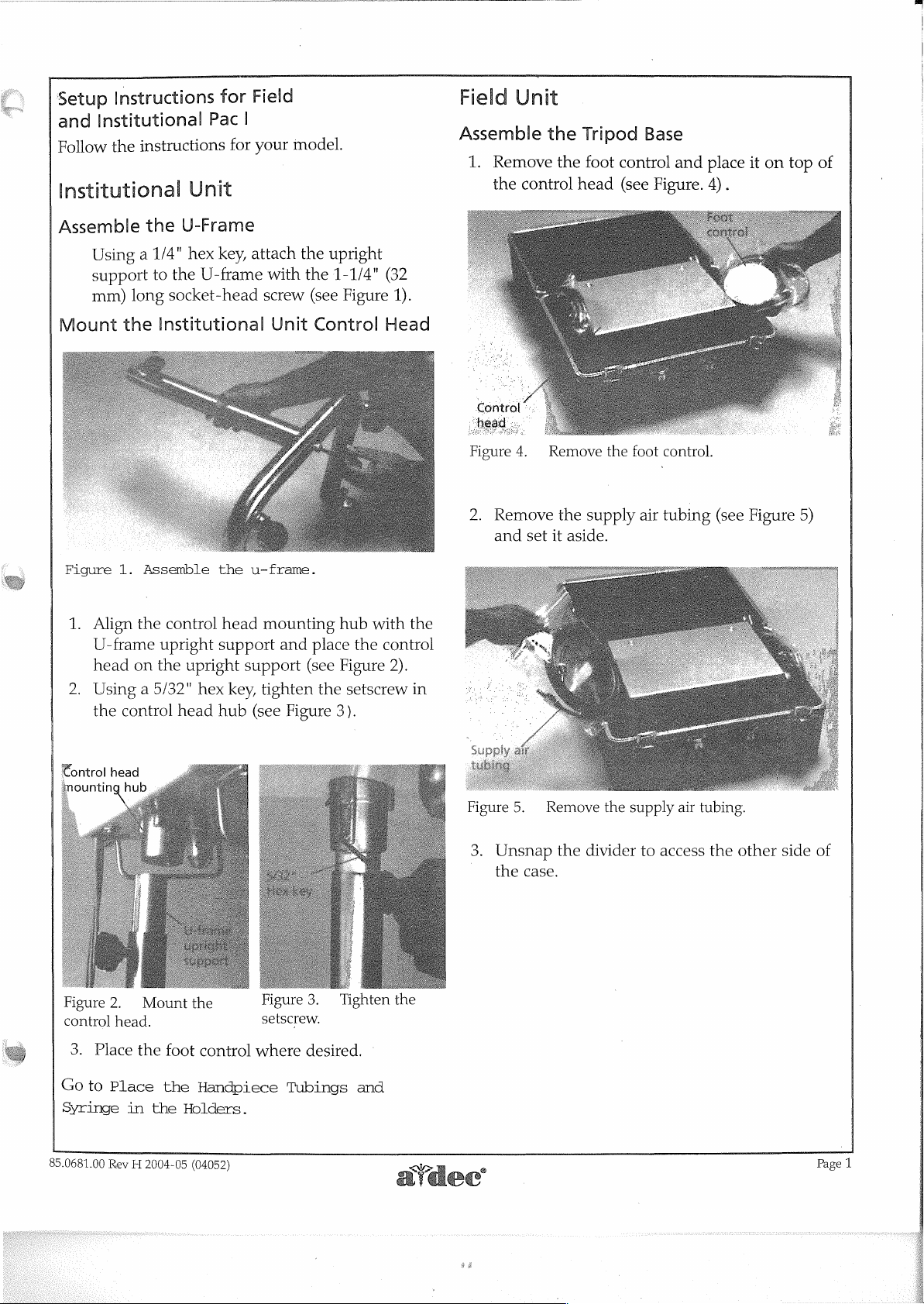
Setup
and
Follow
Institutional
Instructions
Institutional
instructions
the
Pac
Unit
for
|
for
Field
model.
your
Field
Assemble
1.
Unit
Remove
the
control
the
the
Tripod
foot
control
head
(see
Base
and
Figure.
place
4).
it
on
top
of
Assemble
Using a 1/4"
support
mm)
Mount
Figure
1.
2.
the
1.
Align
U-frame
head
Using a 5/32"
the
control
the
U-Frame
hex
to
the
U-frame
long
socket-head
Institutional
Assemble
the
control
upright
on
the
upright
hex
head
key,
attach
with
screw
Unit
^
the
u-frame.
head
mounting
support
support
key,
tighten
hub
(see
the
the
(see
Control
and
place
(see
the
Figure
upright
1-1/4"
Figure
hub
with
the
control
Figure
setscrew
3).
(32
1).
Head
the
2).
in
a
Control
54
Figure
2.
4.
Remove
and
set
2
~
Remove
the
supply
it
aside.
the
foot
air
control.
“
tubing
(see
Figure
5)
€ontrol
Figure
control
Go
Syringe
85.0681.00
3.
Place
to
head
2.
Mount
head.
the
foot
Place
Rev H 2004-05
in
the
the
the
control
Handpiece
Holders.
(04052)
setscrew.
where
Tubings
desired.
:
and
Figure
3.
Unsnap
©
the
5.
case.
No
08
Remove
the
divider
the
supply
to
access
air
tubing.
the
other
side
of
Page
1
Page 6
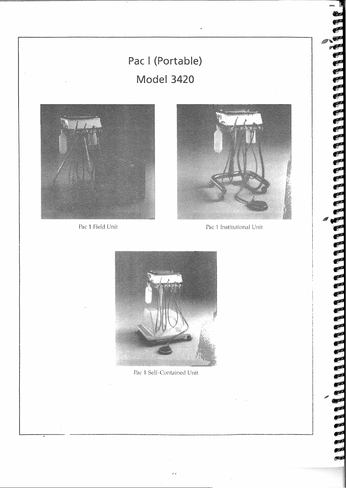
Pac | (Portable)
Pac 1 Field
Unit
Pac
1
Se
IEC
ont
aine
dů
e?
Pa
t
M
|
h
nst
tutional
i
Unit
Page 7
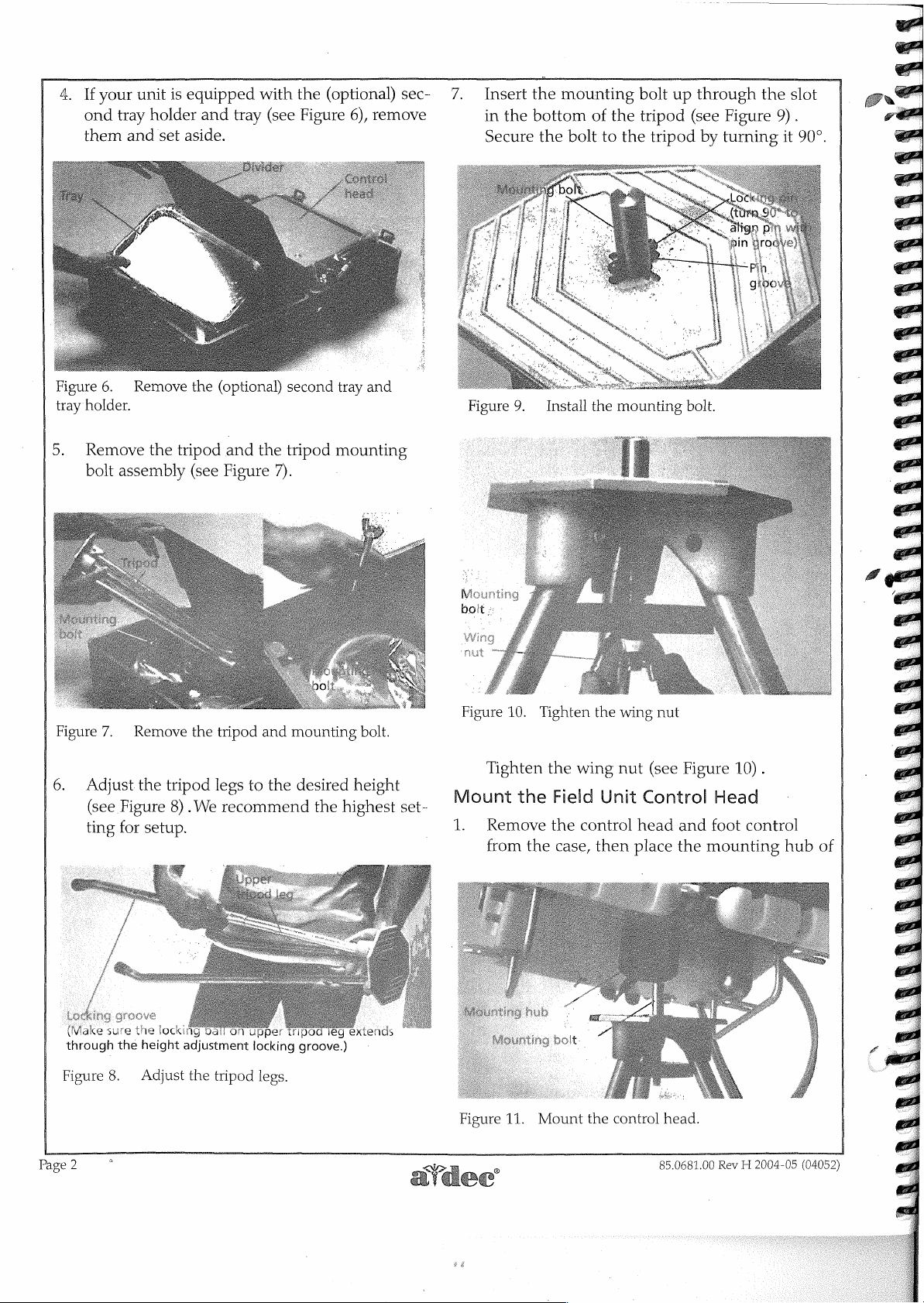
4. If
ーー
2
oa
の
。
ond
them
^
mm
7
TO
a
>
2202
27
your
tray
and
-
/
ντ
24
7
unit
is
holder
set
/
equipped
and
tray
aside.
with
(see
the
(optional)
Figure
6),
remove
sec-
7.
Insert
in
the
Secure
the
mounting
bottom
the
bolt
LA
of
to
the
the
τη
CO
и
bolt
up
tripod
tripod
LILI
~
%
through
(see
Figure
by
turning
9
K
eee
es
|
Kamal
1
nà
4
i
Re
κ
Dr
the
9).
it
slot
90°.
Figure
tray
holder.
5.
Remove
bolt
6.
Adjust
(see
ting
6.
Remove
assembly
Remove
the
Figure
for
setup.
the
tripod
tripod
8) . We
the
(optional)
and
(see
Figure
the
tripod
legs
recommend
the
and
to
second
tripod
7).
mounting
the
desired
tray
mounting
height
the
highest
and
bolt.
“E,
2
set-
Figure
Figure
Mount
1.
9. | Install
e
10.
Tighten
Tighten
the
Remove
from
the
the
wing
Field
the
case,
the
mounting
the
wing
nut
Unit
control
then
head
place
bolt.
nut
(see
Figure
Control
and
the
22
ーー
ca
10).
Head
foot
control
mounting
hub
of
MV
through
Figure
the
8.
height
Adjust
|
the
ON
tripod
adjustment
Upper
locking
legs.
Tripod
groove.)
Page
2
ley
extienda;
SSS
X
Figure
11.
Mount
the
control
85.0681.00
head.
Rev H 2004-05
(04052)
Page 8
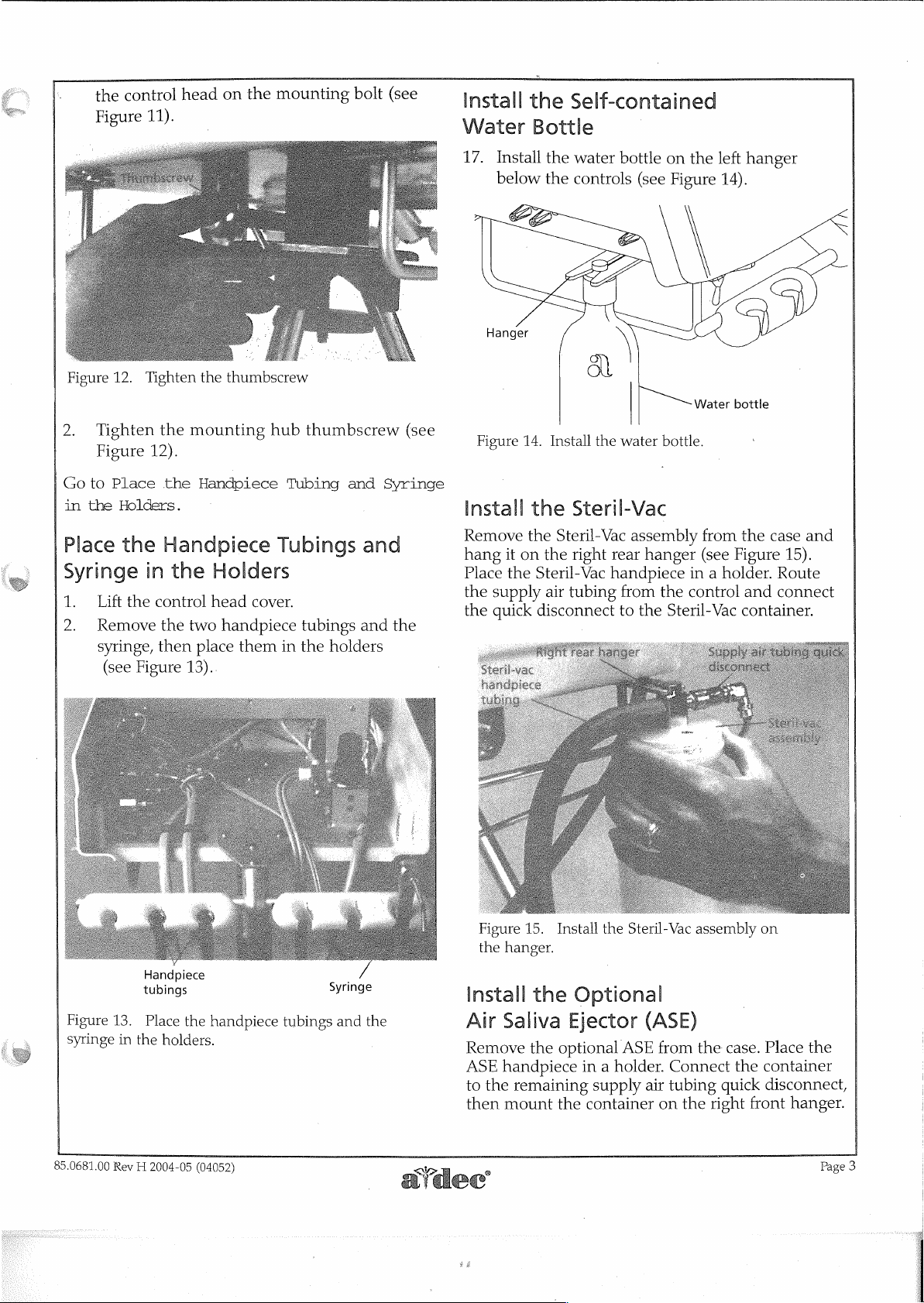
k
the
control
Figure
11).
head
on
the
mounting
bolt
(see
2
Install
Water
17.
>
the
Bottle
Install
below
Hanger
Self-contained
the
water
bottle
the
controls
(see
q
on
the
Figure
left
hanger
14).
Figure
2.
Goto
in
Place
Syringe
1.
2.
12.
Tighten
Figure
Place
the
Holders.
the
Lift
the
Remove
syringe,
(see
Tighten
12).
in
Figure
the
the
mounting
the
Handpiece
Handpiece
the
control
the
two
then
place
13)..
thumbscrew
hub
Tub
Holders
head
cover.
handpiece
them
in
thumbscrew
Tubing
tubings
the
and
ngs
holders
Syringe
and
and
(see
the
Figure
Install
Remove
hang
Place
the
the
14.
the
the
it
on
the
supply
quick
Install
the
Steril-Vac
Steril-Vac
the
right
rear
Steril-Vac
air
disconnect
handpiece
tubing
water
bottle.
assembly
hanger
from
the
to
the
Steril-Vac
Water
bottle
'
from
the
case
(see
Figure
in a holder.
control
and
container.
and
15).
Route
connect
e
Handpiece
tubings
Figure
syringe
85.0681.00
13.
Place
the
in
the
holders.
Rev H 2004-05
handpiece
(04052)
tubings
Syringe
and
the
Figure
the
Install
Air
Remove
ASE
to
then
15.
hanger.
the
Saliva
the
handpiece
the
remaining
mount
Install
Optional
Ejector
optional
the
the
Steril-Vac
(ASE
ASE
from
in a holder.
supply
container
air
tubing
on
assembly
the
Connect
quick
the right
on
case.
Place
the
container
disconnect,
front
the
hanger.
Page
|
|
|
|
3
Page 9
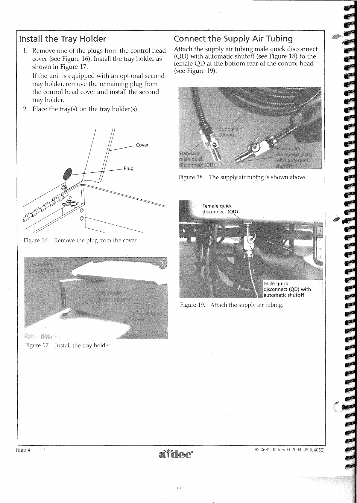
Install
1.
2.
Figure
the
Remove
own
If
the
tray
holder,
the
control
tray
holder.
Place
16.
one
Fi
Fato
im
unit
the
tray(s)
Tray
is
Holder
of
the
16).
177
i
.
equipped
remove
head
cover
on
plugs
from
Install
me
. .
with
the
remaining
and
the
tray
the
control
tray
the
Hay
S
an
optional
plug
install
the
holder(s).
Plug
hold
nl
second
from
second
Cover
head
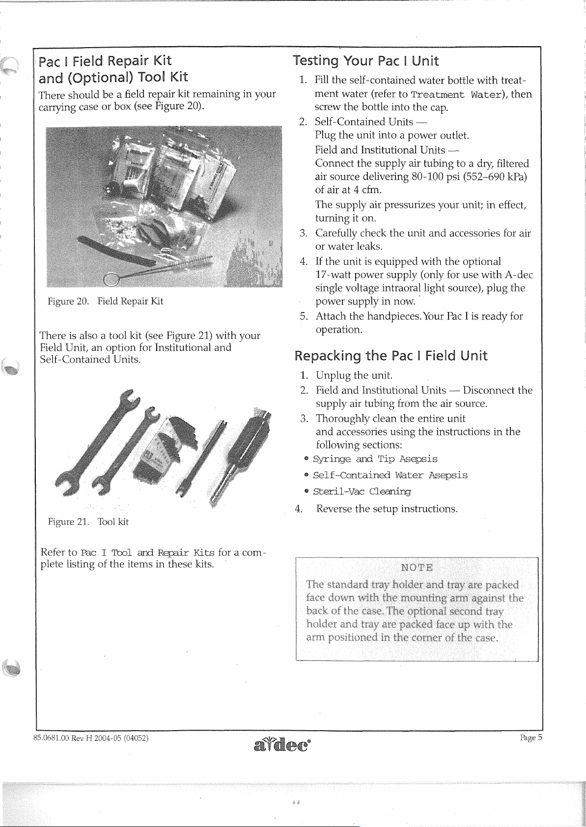
Connect
Attach
(QD)
female
(see
the
with
OD
Figure
the
supply
automatic
the
at
19).
9
S
a
Remove
the
plug.from
the
—_
—
cover.
:.
Female
disconnect
quick
Supply
air
tubing
shutoff
bottom
(QD)
rear
Air
male
(see
of
Tubing
quick
disconnect
Figure
the
18)
control
the
to
head
ο
ο...
Figure
17.
Install
the
ンク
tray
holder.
7
©
22
の
の
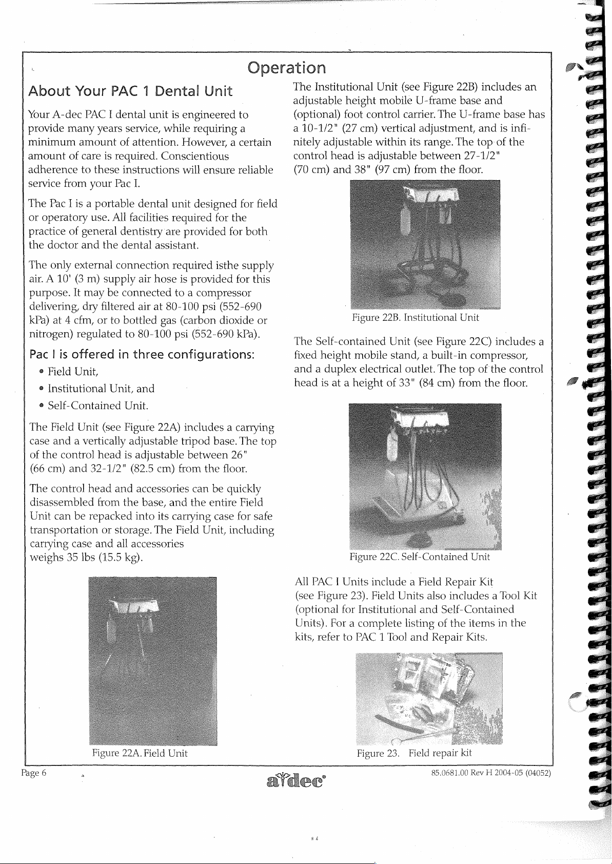
Figure
19.
Attach
the
supply
air
tubing.
ick
]
Page
4
>
85.0681.00
#6
Rev H 2004-05
(04052)
Page 10
Field
|
‘Pac
and
There
carrying
(Optional)
should
case
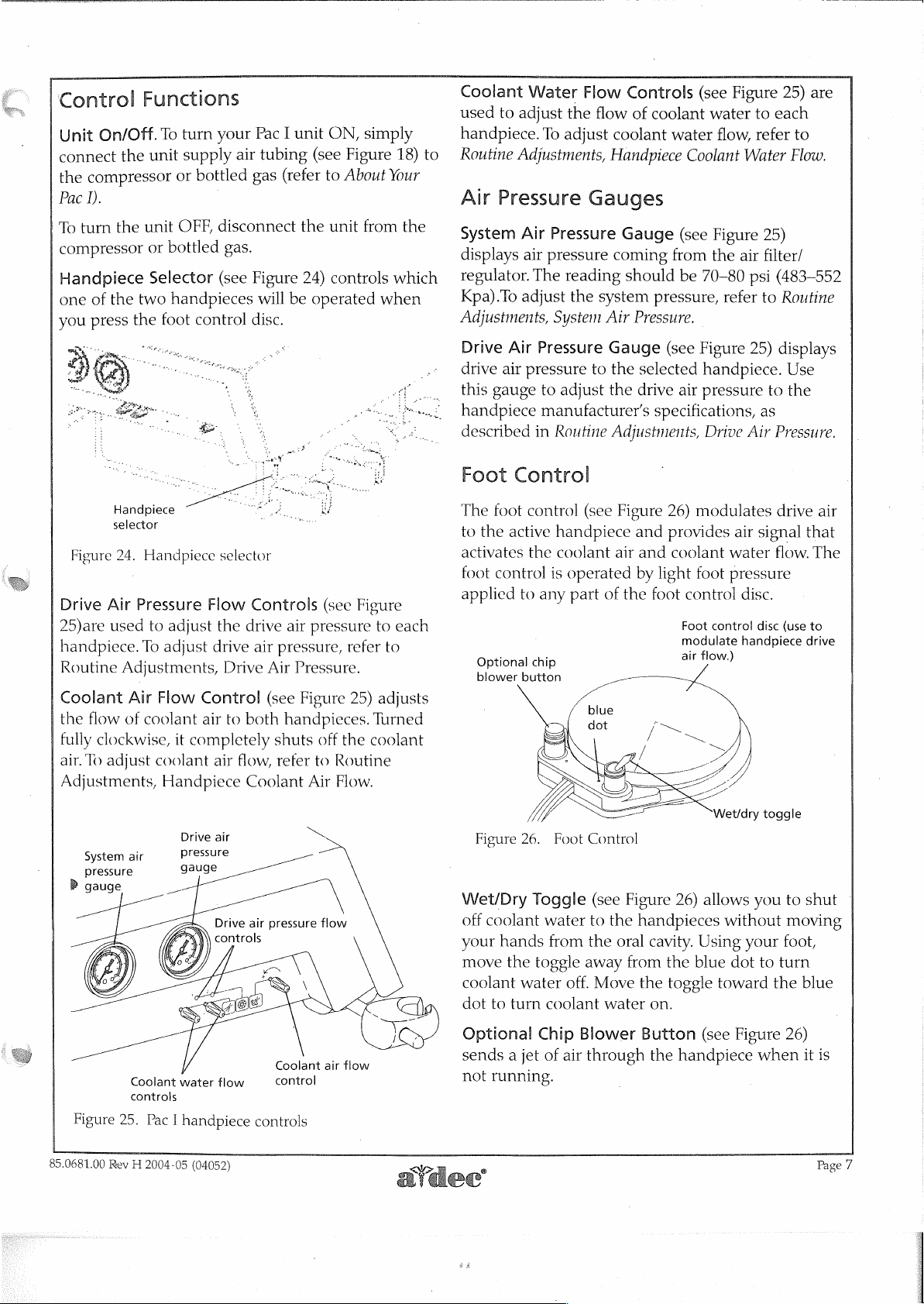
Figure
20.
There
is
also a tool
Field
Unit,
an
Self-Contained
Repair
be a field
or
box
Field
Repair
option
Units.
Kit
Tool
repair
(see
Figure
Kit
kit
(see
for
Institutional
Kit
kit
remaining
20).
Figure
21)
with
and
Figure
21.
Tool
kit
in
your
your
Testing
1.
2.
3.
4.
5.
©
Repacking
1.
2.
3.
®
Syringe
®
Self-Contained
e
Steril-Vac
Your
Fill
the
self-contained
ment
water
screw
the
Self-Contained
Plug
the
Field
and
Connect
air
source
of
air
at 4 cfm.
The
supply
turning
Carefully
or
water
If
the
unit
17-watt
single
power
Attach
operation.
Unplug
Field
supply
Thoroughly
and
following
Reverse
voltage
supply
the
and
air
accessories
Pac | Unit
(refer
to
Treatment
bottle
unit
Institutional
the
it
on.
check
leaks.
power
the
Institutional
and Tip
the
into
Units
into a power
supply
delivering
air
is
equipped
handpieces.
the
unit.
tubing
clean
sections:
Cleaning
setup
air
pressurizes
the
unit
supply
intraoral
in
now.
Pac | Field
from
the
using
Asepsis
Water
instructions.
water
bottle
with
Water),
the
cap.
—
outlet.
Units
—
tubing
80-100
with
(only
light
Your
Units — Disconnect
the
entire
the
to a dry,
psi
(652-690
your
unit;
and
accessories
the
optional
for
use
with
source),
Pac I is
air
unit
instructions
Asepsis
ready
Unit
source.
in
plug
treat-
then
filtered
kPa)
effect,
for
air
A-dec
the
for
the
in
the
Refer
to
Pac I Tool
plete
listing
85.0681.00
of
Rev H 2004-05
the
and
items
(04052)
Repair
in
these
Kits
kits.
for a com-
|
The
face
arm
|
standard
down
k
of
positioned
with
the
case.
d
tray
tray
Nora
holder
the
mo:
The
optional
are
packed
in
the
7
and
|
it
gama
face
corner
second
up
of
the
with
case.
tray
the
Page
5
Page 11
About
Your
provide
minimum
amount
adherence
service
The
or
operatory
practice
the
The
air. A 10'
purpose.
delivering,
kPa)
nitrogen)
Pac | is
e
e
©
Your
A-dec
Pac I is a portable
doctor
only
at 4 cfm,
Field
Institutional
Self-Contained
PAC I dental
many
amount
of
care
to
from your
of
general
and
external
(3
It
may
dry
regulated
offered
Unit,
PAC 1 Dental
years
service,
of
attention.
is
required.
these
instructions
Pac
I.
dental
use.
All
facilities
dentistry
the
dental
connection
m)
supply
be
filtered
or
air
connected
air
to
bottled
to
80-100
in
three
Unit,
and
Unit.
Unit
unit
is
engineered
while
requiring
However, a certain
Conscientious
will
ensure
unit
designed
required
are
provided
assistant.
required
hose
is
to a compressor
at
80-100
gas
(carbon
psi
configurations:
for
isthe
provided
psi
(552-690
peration
to
a
reliable
for
field
the
for
both
supply
for
this
(552-690
dioxide
or
kPa).
The
adjustable
(optional)
a
10-1/2"
nitely
control
(70
|
The
fixed
and a duplex
head
Institutional
height
foot
control
(27
cm)
adjustable
head
cm)
and
Self-contained
height
is
at a height
within
is
adjustable
38"
(97
Figure
mobile
electrical
Unit
(see
Figure
mobile
vertical
22B.
U-frame
carrier.
cm)
Institutional
Unit
stand, a built-in
outlet.
of
33"
The
adjustment,
its
range.
between
from
the
(see
Figure
The
(84
cm)
22B)
includes
base
and
U-frame
and
The
top
27-1/2"
floor.
Unit
22C)
compressor,
top
of
the
from
the
an
base
has
is
infi-
of
the
includes
control
floor.
a
The
Field
Unit
(see
case
and a vertically
of
the
control
(66
cm)
The
control
disassembled
Unit
can
transportation
carrying
weighs
and
head
be
repacked
case
35
lbs
head
32-1/2"
from
or
and
(15.5
Figure
adjustable
is
adjustable
(82.5
cm)
and
accessories
the
base,
into
its
storage.
all
The
accessories
kg).
22A)
includes a carrying
tripod
from
and
carrying
Field
base.
between
the
floor.
can
be
the
entire
case
Unit,
The
top
26"
quickly
Field
for
safe
including
All
PAC I Units
(see
Figure
(optional
Units).
kits,
For a complete
refer
Figure
22C.
include a Field
23).
Field
for
Institutional
to
PAC 1 Tool
Self-Contained
Repair
Units
also
includes a Tool
and
Self-Contained
listing
and
of
the
Repair
Unit
Kit
items
Kits.
in
Kit
the
Figure
Page
6
a
22A
Field
Unit
Figure
23.
Field
repair
kit
85.0681.00
Rev H 2004-05
(04052)
He
Page 12
Control
On/Off.
Unit
connect
the
Pac
To
compressor
Handpiece
one
you
the
compressor
I).
turn
the
of
the
press
the
Functions
turn
To
unit
supply
or
bottled
unit
OFF,
or
bottled
Selector
two
handpieces
foot
control
Pac
your
air
tubing
gas
|
disconnect
gas.
(see
Figure
will
disc.
ON,
unit
I
(see
(refer
to
the
24)
be
operated
simply
Figure
About
unit
from
controls
when
18)
Your
the
which
Coolant
used
handpiece.
Routine
to
Air
System
displays
regulator.
Kpa).To
Adjustments,
Water
to
adjust
Adjustments,
the
To
adjust
Pressure
Air
Pressure
air
pressure
The
reading
adjust
the
System
Flow Controls
flow
of
coolant
coolant
Handpiece
water
Coolant
Gauges
Gauge
coming
should
system
Air
Pressure.
(see
from
be
pressure,
-
(see
Figure
water
flow,
Figure
the
70-80
refer
to
refer
Water
25)
air
filter/
psi
to
25) are
each
to
Flow.
(483-552
Routine
Drive
25)are
handpiece.
Routine
Coolant
the
fully
air.
Adjustments,
Handpiece
selector
Figure
24.
Air
used
Adjustments,
flow
of
clockwise,
To
adjust
Handpiece
Pressure
to
adjust
To
adjust
Air
Flow
coolant
it
coolant
Handpiece
selector
Flow
Controls
the
drive
drive
air
Drive
Air
Control
air
completely
air
(see
to
both
flow, refer
Coolant
Ш
o
(see
air
pressure
pressure,
Pressure.
handpieces.
shuts
refer
Figure
off
to
Routine
Air
Flow.
25)
the
Figure
to
each
to
adjusts
Turned
coolant
Drive
drive
this
handpiece
described
The
to
activates
foot
applied
gauge
Foot
foot
the
control
Optional
blower
Air
air
pressure
Control
control
active
the
to
chip
button
Pressure
to
adjust
manufacturer's
in
Routine
handpiece
coolant
is
any
Gauge
to
the
the
Adjustments,
(see
Figure
air
operated
part
of
the
selected
drive
and
and
by
(see
Figure
handpiece.
air
pressure
specifications,
26)
modulates
provides
coolant
light
foot
foot
control
Foot
modulate
air
flow.)
Drive
air
water
pressure
disc.
control
handpiece
25)
to
as
Air
signal
disc
displays
Use
the
Pressure.
drive
air
that
flow.
The
(use
to
drive
Drive
air
System
air
pressure
P
gauge
Coolant
controls
Figure
25.
85.0681.00
Rev H 2004-05
pressure
gauge
o
AM
|
water
Pac I handpiece
(04052)
AT
Drive
controls
flow
air
controls
OA
pressure
Coolant
control
flow
air
flow
Figure
26.
Wet/Dry
off
coolant
your
move
coolant
dot
Optional
sends a jet
not
Toggle
hands
the
toggle
water
to
turn
Chip
running.
Foot
Control
(see
water
to
from
the
away
off.
Move
coolant
Blower
of
air
through
Figure
the
handpieces
oral
cavity.
from
the
water
on.
Button
the
26)
allows
without
Using
the
blue
toggle
toward
(see
handpiece
you
your
dot
to
Figure
when
to
shut
moving
foot,
turn
the
blue
26)
it
©
is
Page
7
Page 13
Routine
System
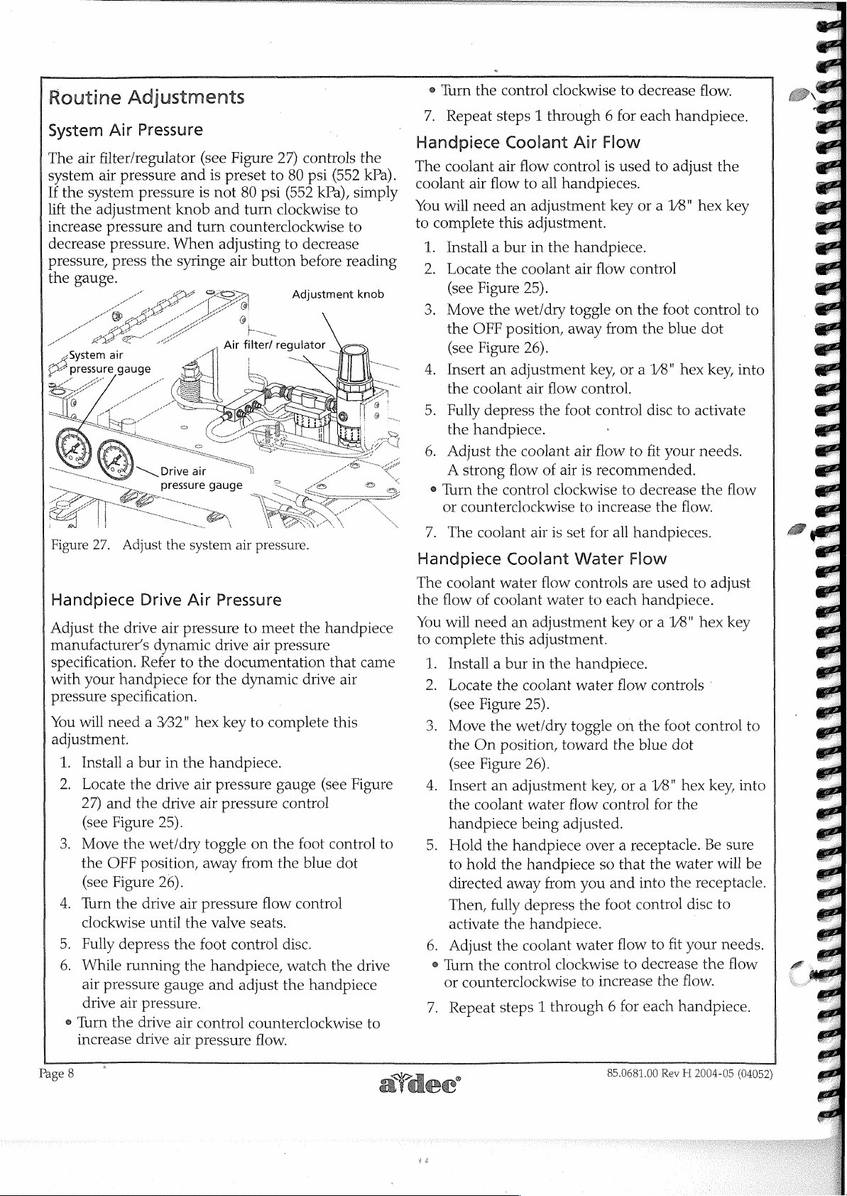
The
air
system
If
the
system
lift
the
adjustment
increase
decrease
pressure,
the
gauge.
Adjustments
Air
Pressure
filter/regulator
air
pressure and
pressure
pressure
pressure.
press
the
) — Drive
pressure
(see
is
knob
and
turn
When
syringe
air
is
not
and
gauge
Figure
preset
counterclockwise
adjusting
air
to
80
psi
turn
button
27)
controls
80
psi
(552
kPa),
clockwise
to
decrease
before
Adjustment
the
(552
kPa).
simply
to
to
reading
knob
e
Turn
the
7.
Repeat
Handpiece
The
coolant
coolant
You
to
1.
2.
3.
4.
5.
6.
air
will
need
complete
Install a bur
Locate
(see
Figure
Move
the
OFF
(see
Figure
Insert
the
coolant
Fully
depress
the
handpiece.
Adjust
A
strong
@
Turn
the
or
counterclockwise
=
control
steps 1 through 6 for
Coolant
air
flow
this
the
the
position,
an
the
control
clockwise
Air
flow
control
to
all
handpieces.
an
adjustment
adjustment.
in
the
handpiece.
coolant
25).
wet/dry
26).
adjustment
air
coolant
flow
air
toggle
away
flow
the foot
air
of
air
clockwise
Flow
is
key
flow
on
from
key,
control.
control
flow
is
recommended.
to
increase
to
decrease
each
handpiece.
used
to
adjust
or a 18"
control
the foot
the
blue
or a V8" hex
disc
to
to
fit
your
to
decrease
the
flow.
flow.
the
hex
key
control
dot
activate
needs.
the
key,
flow
to
into
Figure
27.
Adjust
Handpiece
Adjust
manufacturer’s
specification.
with
pressure
You
adjustment.
Page
the
your
specification.
will
need a 332"
1.
Install a bur
2.
Locate
27)
and
(see
Figure
3.
Move
the
OFF
(see
Figure
4.
Turn
clockwise
5.
Fully
6.
While
air
pressure
drive
e
Turn
the
increase
8
handpiece
the
the
depress
air
the
Drive
drive
air
dynamic
Refer
in
the
drive
the
drive
25).
wet/dry
position,
26).
drive
until
the
running
gauge
pressure.
drive
drive
air
system
Air
Pressure
pressure
drive
to
the
documentation
for
the
hex
key
the
handpiece.
air
pressure
air
pressure
toggle
away
air
pressure
the
valve
foot
the
handpiece,
and
air
control
pressure
air
pressure.
to
meet
air
dynamic
to
complete
on
the
from
flow
seats.
control
adjust
counterclockwise
flow.
the
handpiece
pressure
that
drive
this
gauge
the
(see
control
foot
control
blue
control
disc.
watch
the
the
handpiece
came
air
Figure
dot
drive
to
to
<>
7.
The
Handpiece
The
coolant
the
flow
You
will
to
complete
1.
Install a bur
2.
Locate
(see
3.
Move
the
(see
4.
Insert
the
handpiece
Hold
DI
to
directed
Then,
activate
6.
Adjust
e
Turn
or
7.
Repeat
m
ἵ
coolant
of
need
Figure
On
Figure
coolant
the
hold
the
counterclockwise
air
is
set
Coolant
water
flow
coolant
this
the
the
position,
an
the
fully
the
steps 1 through 6 for
water
an
adjustment
adjustment.
in
the
coolant
25).
wet/dry
26).
adjustment
water
being
handpiece
handpiece
away
from
depress
the
handpiece.
coolant
control
clockwise
toward
flow
adjusted.
for
all
handpieces.
Water
controls
handpiece.
water
toggle
over a receptacle.
you
the
water
to
Flow
are
to
each
handpiece.
key
or a 1/8"
flow
on
the foot
the
blue
key,
or a 1/8”
control
so
that
and
into
foot
control
flow
to
decrease
increase
each
85.0681.00
used
controls
dot
hex
for
the
the
water
the
to
fit
the
handpiece.
Rev H 2004-05
to
adjust
hex
key
control
Be
receptacle.
disc
|
your
the
flow.
key,
into
sure
will
to
needs.
flow
(04052)
to
be
Page 14

1.
Autoclavable
designed
The
are
use
located
is
this
of
sure
is
syringe
provided
in
be
can
manual.
Syringe
the
(refer
syringe
Your
operatory.
normal
which
instructions
section
Autoclavable
1.
Make
2.
Insert a syringe
retainer
3.
Air — Depress
4.
Water — Depress
5.
Spray — Depress
Syringe
be
to
subject
parts
a
in
repair
field
the
the
found
unit
to
in
is
tip
into
Changing
the
right
the
both
Operation
on.
the
left
buttons.
serviced
easily
wear
to
syringe
button.
button.
repair
Repair
kit.
Maintenance
syringe
the
Syringe
tip
the
in
under
kit
Tip).
Adjust
flow.
29),
e
e
2.
Press
time
flow
desired
9
©
Disconnecting
the
Press
then
turn
Turn
the
adjustment
decrease
Turn
(out)
Turn
decrease
Turn
(out)
water
the
adjustment
to
increase
the
air
for
spray
adjustment
spray.
the
adjustment
the
adjustment
to
increase
water
spray.
the
and
the
to
left
the
flow.
water
(see
screw
achieve
(water)
water
flow
screw
screw
water
Syringe
Figure
to
screw
screw
spray.
flow.
buttons
29),
achieve
the
desired
button
adjustment
clockwise
counterclockwise
at
then
clockwise
counterclockwise
Head
(see
the
turn
the
rate
Figure
screw.
(in)
to
same
the
(in)
to
of
air
Air
y
LA
Figure
Syringe
The
dual
(see
controls
flow,
pinch
the
water
the
Air
manifold
28.
syringe
pinch
Figure
follow
valve.The
air
filter
tubing
control
filter
Le
Deği
`
Adjust
Flow
air
valve
28).
the
air
each
regulator
is
head.
Dual
|
Water
SÅ
the
syringe
Adjustment
and
water
flow
located
To
flow
length
syringe
connected
pinch
inside
identify
which
and
which
of
tubing
air
manifold
to
valve
tubing
air
and
are
controlled
the
control
adjustment
controls
through
is
and
the
the
red
Autoclavable
ως
Syringe
Spray
\
LA
water
flows.
by
head
screw
the
water
the
connected
syringe
tubing
inside
gez?
$555
97
2
a
dual
to
Disconnect
the
system
Turn
the
syringe
syringe
syringe
When
water,
tubing,
A-dec
separates
head
the
syringe
which
will
Syringe
the
of
air
away
is
drip
air
supply.
and
handle
from
from
head
left
inside
out.
Tips
Use
the
syringe
water
pressure.
counterclockwise
the
handle
the
is
disconnected a little
of
then
terminal.
the
syringe
to
until
pull
head
bleed
the
the
and
Figure
29.
Adjust
85.0681.00
Rev H 2004-05
the
system
(04052)
air
pressure.
i
TT
hree
Saeco
grooves
"a"
mark
Page
9
Page 15

A-dec
Changing
To
of
the
To
is
important
Syringe
remove
syringe
ensure
À
Figure
30.
Push
the
assembly.
“clicks”
assembly
two
use
retainer
syringe
assembly
as
“clicks”
the
syringe.
assembly
tip
the
Syringe
the
A-dec
tip
that
the
that
you
o
CN
Changing
syringe
As
you
O-rings
slide
into
when
The
to
be
ejected.
must
be
Tips
Tip
syringe
retainer
syringe
tip
push
inside
installing
are
repaired
assembly
will
install
=.
an
A-dec
into
the
the
the
the
grooves.
O-rings
damaged
The
tip
before
tip,
pull
perform
the
tip
New
grooves
A-dec
syringe
syringe
in
you
syringe
If
the
syringe
inside
and
syringe
it
straight
(see
Figure
properly,
correctly.
tip
has
three
and
an
“a”
marking
tip.
tip
retainer
will
feel
tip
retainer
you
do
not
tip,
do
the
syringe
may
allow
tip
retainer
using
the
syringe.
out
30).
it
two
feel
not
tip
the
Syringe
All
syringe
must
syringe
heat
Pre-Cleaning
1.
Remove
retainer
syringe
Syringe
2.
If
gently
nylon
Remove
Go
4.
“solution
5.
your
6.
and
tips
be
heat
sterilized
and
syringe
sterilized.
the
and
terminal
Head
the
threads
brush
or
brass
the
Immerse
Clean
instructions
Purge
syringe
the
until
the
ultrasonic
all
cleaning
tips.
Tip
Asepsis
are
considered
tips
syringe
remove
(refer
on
page
on
the
the
threads
bristle
syringe
tip
in
ready
syringe
provided
cleaning
critical
between
have
tip
the
syringe
tip
an
for
tips
agents
patients.
been
designed
from
the
syringe
to
Disconnecting
9).
head
free
of
brush.
for
sterilization.
appropriate
ultrasonic
ultrasonically.
by
the
manufacturer
equipment.
from
items
The
syringe
head
from
appear
debris
holding
cleaning.
Follow
the
syringe
and
to
be
tip
the
the
dirty,
using
of
and
a
the
When
the
Figure
After
and
tip
An
water
properly
A-dec
Correct
31.
installing a tip,
press
is
properly
improperly
to
enter
installed,
syringe
No
showing.
is
properly
installed.
Installing
the
tip
grooves
this
air
button
installed.
installed
the
air
none
of
the
are
visible
are
tip
the
A-dec
point
several
A-dec
tubing
Incorrect
syringe
the
syringe
syringe
in
(see
A
This
installed.
times
the
syringe
groove
grooves
Figure
is
tip
is
improperly
tip.
at
the
to
be
tip
allows
tip.
on
31).
showing.
floor
sure
the
Sterilization
1.
Rinse
the
syringe
in
clear
water.
2.
Use a dispensing
alcohol
the
3.
Sterilize
e
Sterilize
steam
[135°C]
(340°F
e
Sterilize
autoclave
(275°F
or
Harvey’s
tips.
the
syringe
autoclave
maximum
[170°C]
the
or
[135°C]
syringe
syringe
chemical
and
syringe
bottle
tips
or
maximum
maximum
to
Vapo-Steril®
tips
using
chemical
temperature),
using
vapor
tips
flush
isopropyl
through
and/or
temperature).
temperature).
the
methods
vapor
the
methods
syringe.
(275°F
or
dry
of
heat
of
steam
Page
10
85.0681.00
Rev H 2004-05
(04052)
Page 16

Handpiece
Your
handpiece
A-dec’s
flushes
than
control
connected
How
Handpiece
After
At
Flushing
Locate
underside
handpiece
more
is
normally
only.
Often
Each
Flush
the
Beginning
Flush
the
water
The
when
Tubings?
Patient:
the
handpiece
of
the
Tubing
control
possible
handpieces
flushing
Should | Flush
the
tubings
of
the
tubings
Handpiece
control
Flush
system
tubing
through
when
the
for
Each
Day:
for
flush
head
flush
the
should
tubings.
20-30
2-3
Tubings
toggle
System
in
equipped
system.
tubings
operating
the
minutes.
(see
The
not
seconds.
on
the
Figure
Handpiece
toggle
in
less
the
be
32).
with
system
time
foot
flush
Self-Contained
The
A-dec
to
optimize
allows
from
©
e
e
Air
(regulated
40
psi
Figure
self-contained
the
quality
you
to
control
dental
Arin
(connected
the
to
source
handpieces
Selecting a quality
treatment
Performing
waterlines
Maintaining
prevent
control
yellow
[276
34.
water
asepsis
with
clean
accumulation
一
一 一
一 一
inside
head
tubing)
to
Kpal)
Adjust
the
Water
of
the
and
proper
system
System
water
system
your
dental
quality
source
and
dental
ἛἊ
of
syringes
for
treatment
disinfectant
unit
of
contaminates.
air
pressure.
is
designed
unit
water.
water
expelled
by:
dental
unit
of
your
waterlines
Water
out
(connected
the
control
to
red
tubing)
It
to
inside
head
Figure
32.
Pac I flush
Gather
coolant
Figure
water
receptacle.
Move
for
between
day.
in
Replace
85.0681.00
up
and
33).
will
the
flush
the
appropriate
patients
Water
the
On
the
Rev H 2004-05
all
the
hold
Be
sure
be
directed
toggle
flows
position.
handpiece
toggle
handpiece
them
over a water
you
hold
away
to
the
time
required,
or
flushing
only
as
long
tubings
(04052)
tubings
the
tubings
from
you
On
position
at
the
as
you
in
that
use
receptacle
so
that
and
into the
|
and
either
their
for
beginning
hold
the
holders.
water
(see
the
hold
flushing
of
the
toggle
How
It
Works
Air,
regulated
water
bottle
the
bottle
the
water
tube
and
the
syringes.
Benefits
system
conjunction
treatment
monitoring.
water
bottle,
How
The
self-contained
depends
municipal
the
whenever
procedure,
source
are
system
and a water
to
correct
self-contained
quality.
to
through a restrictor
cap.
The
from
out
to
of
using
only
with
protocol
The
include
Choose
water
water
on
the
source
treatment
that
40
psi
air
pressure
the
bottle
the
handpiece
the
A-dec
fully
realized
an
A-dec
and
three
main
the
treatment
Treatment
to
use
system
quality
and
the
water
water
you
are
(276
kPa),
is
supplied
barb
attached
in
the
bottle
up
into
the
water
control
self-contained water
when
recommended
followed
components
treatment
protocol.
Water
in
your
(for
of
water
goals
you
system.
is
specified
consistent
blocks
used
by
periodic
water,
A-dec
patient
available
have
It
is
important
for
in
your
to
the
to
forces
pickup
and
in
waterline
of
the
the
water
treatment)
from
your
for
using
that
a
water
Page
11
Page 17

Tap
water
If
you have
ered
by
using
system.
tion
with
dures
procedures
water
counts.
Distilled
If
you
delivered
ommend
under
Pharmacopoeia
standards
tions.
operate
|
ICX
Water
A-dec
flushing
contamination
waterlines.
bottle
continuously
was
developed
effective
Page
12
confidence
your
municipal
fresh
tap
water
Use
of
tap
the
operation
prescribed
in
this
that
contains
water
have
concerns
through
the
use
the
standards
(U.S.P.).
has
been
Most
reputable
under
ICX
refill, a low
U.S.P.
Treatment
offers a unique
and
maintenance.
and
By
adding
assured
to
method
ES
in
the
quality
supply,
in
your
self-contained
water
must
and
maintenance
in
this
manual.
manual
higher
your
of
water
processed
WARNING
maintains
concentration
be
for
can
than
about
of
standards.
treating
the
municipal
which
the
United
Water
bottled
Tablet
solution
It
one
tablet
in
the
dental
the
most
water
helps
self-contained
you
be
done
Failure
result
normal
quality
supply,
has
distilled
in
optimum
clean
of
of
compatible
of
water
may
consider
in
conjunc-
proce-
to
follow
in
dental
microbe
of
water
we
been
distilled
States
under
condi-
companies
“pi
SAFA
LE
Ware
for
waterline
prevent
dental
ICX
cleaner
unit
unit
to
each
is
water.
and
deliv-
water
all
unit
rec-
these
ar
ICX
dental
al
unit
water
systems.
waterline
A-dec
ICX
A-dec
an
empty
The
The
regular
How
Before
water
higher
Waterline
use.
have
Association
Center
500
Standards
Refer
recommendations
steps
1.
2.
3.
4.
5.
NOTE:
ἵ
maintenance
ICX
water
Water
ICX
is
self-contained
tablet
is
®
Eliminate
e
Help
deter
e
Provide a residual
clean
ICX
tablet
testing
to
Use
using
quality.
than
Preparation
Recommendations
been
published
for
Disease
cfu/ml.
specify a maximum
to
your
below
Before
day,
empty
the
bottle.
Drop
tablet
contamination,
Fill
bottle
dental
Wait
60
Connect
unit
ON.
If
you
equipment
recommend a special
prepare
Waterline
©
A-dec's
is
treatment
Treatment
an
effervescing
formulated
odors
prevent
contamination
waterlines
ICX
A-dec
your
(ADA)
European
describe
refilling
unit.
seconds
build-up
during
should
of
If
results
national
with
the
are
the
be
treatment
ICX
water
for
by
not
Control
Union
regulatory
specific
how
bottle
any
remaining
into
empty
avoid
water,
for
air
supply
using
that
has
system
Preparation
for
indicate
quality
for
to
this
recommendation
based
bottle
to:
effect
used
the
tablet
on
tablet.
Protocol
tablet
before
of
deposits
in
dental
that
periods
in
conjunction
water.
the
first
bacterial
goals,
ICX,
otherwise
dental
exceed
(CDC)
to
to
and
touching
and
product
already
startup
for
unit
American
200
Drinking
of
100
authorities
your
use
ICX.
at
the
water
bottle.
connect
to
fully
tubing
been
the
usage
for
ICX).
85.0681.00
daily
that
unit
helps
time,
not
local
(To
the
and
for
procedure
Rev H 2004-05
for
use
of
is
added
each
filling.
and
help
waterlines
maintain
of
non-use.
test
counts
proceed
begin
water
Dental
cfu/ml
to
Water
cfu/ml.
start
left
prevent
dissolve.
|
the
in
of
quality
and
exceed
for
area.
The
of
every
in
tablet.)
to
turn
the
first
time
use,
we
to
ICX
(see
the
to
with
your
to
daily
the
on
(04052)
Page 18

-Steril-Vac
A-dec
Your
central
evacuation
System)
handpiece
liter)
waste
liter)
waste
Operating
Air
is
(QD)
To
actuate
button
button
Steril-vac
disconnect
Steril-Vac
vacuum.
system
handpiece.
forces
container.
container
supplied
tubing
the
on
the
is
spring
quick
Supply
air
tubing
quick
disconnect
(QD)
is
It
using
the
Your
by
attaching
to
the
vacuum,
AVS
loaded
(QD)
eliminates
operated
air
an
A-dec’s
Vacuum
debris
An
is
Steril-Vac
steril-vac
handpiece
Waste
container
created
into
(optional)
available.
the
QD
press
and
(see
to
the
Off
need
the
oral
(Air
AVS
πε
at
the
one
two
quick
disconnect
(see
Figure
hold
the
Figure
position.
AVS
handpiece
Actuation
button
a
for
Vacuum
|
quart
quart
35).
35).
The
(.95
(1.9
Cleaning
After
thoroughly
the
AVS
the
system
the
tubing.
Remove
disinfecting.
recommendations.
Daily
prevent
cleaners
vacuum
dealers.
follow
use a sudsing
Use
the
clean
way
past
of
the
hold
purged
The
Steril-Vac
and
disinfected
Your
each
patient,
rinsed
handpiece.
for a few
the
handpiece
Consult
cleaning
accumulation
systems
If
the
brush
the
AVS
the
from
of
with
disinfectant
you
use
manufacturer’s
detergent
provided
AVS
handpiece.
the
cross
handpiece.
button
the
waste
Steril-Vac
the
Steril-Vac
by
drawing
After
rinsing,
seconds
tip
for
your
dental
the
AVS
handpiece
of
debris.
properties
are
available
one
of
these
recommendations.
to
in
the
Push
tube
to
clean
Rinse
down
each
until
tubing.
container
time
it
clean
to
clear
cleaning
Several
from
cleaners,
clean
field
the
with
all
the
should
is
emptied.
should
water
draw
all
supply
is
for
dental
the
AVS.
repair
brush
the
lower
clean
water
be
be
through
air
through
water
from
and
dealer
necessary
special
dental
be
water,
supply
sure
Never
kit
to
all
the
portion
then
has
been
cleaned
for
to
to
|
Figure
35.
Steril-Vac
85.0681.00
Rev H 2004-05
(04052)
Page
13
Page 19

Oil
The
your
normal
e
e
®
lection
Co
gauze
pad
unit
needs
usage.
Remove
discard
Fold
in
gauze
the
jar.
Screw
Do
not
System
(2x2)
inside
to
be
changed
Change
the
the
quarters a new
pad
the
oil
overtighten.
more
oil
collector
old
gauze
and
place
collector
the
oil
collector
once a week
often
for
jar
from
(see
Figure
two-inch
against
jar
onto
the
the
jar
for
heavy
the
unit
36).
square
spring
unit.
on
use.
and
inside
Care
For
refer
Publication
Instructions
recommended
to
Equipment
No.85.0696.00).
asepsis
Asepsis
instructions,
Owner's
Guide
(A-dec
Gauze
(2x2)
Figure
pad
36.
>YL
|
Oil
Collection
collector
Oil
System
-一
Discard
gauze
jar
—
used
pad
Page
14
85.0681.00
Rev H 2004-05
(04052)
Page 20

aintenance
General
Parts
the
In
will
find
for
possible
The
seal
an
O-ring),
the
seal
Defects
A
careful
surfaces
flaws
When
gaskets
install
components.
re-used,
cracks.
Cleaning
Service
Inspection
troubleshooting
references
area
groove
in
any
examination
with a magnifier
that
are
servicing
or
diaphragms
new
ones
carefully
Internal
defect,
is
comprised
the
bore
in
the
of
these
too
small
components
when
If
the
inspect
Information
sections
to
the“seal
which
old
will
of
the
or
seat
in
valve
stem
areas
may
of
all
sealing
is
essential
to
see
that
it
is
generally
reassembling
gasket
the
item
Parts
manual
this
in
area"
as
a
location
allow
a
valve
seal
itself
the
valve
body,
or
piston.
result
in
parts
for
detecting
otherwise.
have
rubber
advisable
the
or
diaphragm
for
pin
you
to
leak.
(usually
and
leakage.
and
to
is
to
holes
or
O-ring
These
miniature
the
four
equipment.
tools
are
-
Figure
|
Hemostats
Hemostats
air
or
water
troubleshooting
be
Tools
tools
allow
components.
smallest
Instructions
included
37.
O-ring
are
flow
quick
O-ring
with
一
575
6
O
Ó- < ンプ
Tools
useful
through
or
repairing
field
repair
The
three
sizes
in
for
the
the
set.
a
σσ
<
ング
(A-dec
for
Part
temporarily
the
tubing
the
of
tools
A-dec
use
of
^
^
No.
unit.
most
A-dec
in
this
the
O-
-ring
009.013.00)
stopping
while
|
set
fit
When
component
cleaned
reassembly.
parts
most
Any
cloth.
them
Tool
Included
(Part
equipped
Institutional
like
A-dec
Unit
for a complete
The
useful
servicing
disassembled
and
inspected
The
is
largely
effective
wiping
Flush
in
and
No.
to
order
for
Tool
following
for
cleaner
should
all
isopropyl
Repair
with
your
45.0439.00).
with a tool
and
the
the
Pac I Institutional
Kit
(Part
Pac I maintenance
dental
lubricant
impervious
parts
listing
items
systems,
should
for
defects
recommended
to
is a hot
be
done
with
clear,
alcohol.
Kits
Pac I Unit
The
Pac I Field
kit.
If
you have
Self-Contained
tool
kit,
ask
No.
45.0438.00).
of
the
are
not
the
parts
be
thoroughly
before
chemical
detergent
with a soft,
hot
is a Field
your
or
items
necessary
and
solvents.
solution.
lint
water
Repair
Unit
the
Unit
and
dealer
Self-Contained
Refer
in
these
but
service.
of
any
for
these
free
and
rinse
is
Pac 1 '
would
or
call
to
page
kits.
may
The
Kit
34
be
Figure
Valve
The
pilot-operated
used
75
10x
The
parts
Test
valve
to
psi
(518
Figure
(A-dec
Magnifier
10x
for
38.
Hemostats
Syringe
test
syringe
valves.
apply a static
kPa).
39.
Valve
Part
No.
magnifier
defects.
S
~ 一 ~
(A-dec
is
used
The
valve
pressure
Test
Syringe
98.0050.00)
is
used
to
«II
Part
No.
to
make
test
syringe
of 5 (34.5
inspect
23
009-008-00)
quick
tests
can
kPa)
to
miniature
valve
of
be
85.0681.00
Rev H 2004-05
(04052)
Figure
40..
10X
Magnifier
(A-dec
Part
No.
009.009.00)
Page
15
Page 21

Test
Gauge
The
test
ous
points
required
e
One
A-dec
®
One
A-dec
e
One
A-dec
e
Two
A-dec
e
1/8"
A-dec
gauge
is
used
while
troubleshooting
for
use
of
1%"
(3.2mm)
Part
No.
washer,
Part
No.
plastic
uni-clamps
(3.2mm)
Part
No.
Part
No.
Part
No.
tee,
to
check
this
gauge:
barb,
023.028.00.
004.005.00.
023.014.00.
for
1/8"
(3.2mm)
025.007.00.
Clear
tubing,
024.015.00.
air
pressure
the
system.
2'
(610mm)
at
vari-
Also
tubing,
long,
A-dec
The
Sleeve
A-dec
14"
(6.4mm)
place
when
Figure
44.
Hex
Wrench
A
complete
wrenches
A-dec
wrenches
eguipment.
Tool
(included
Sleeve
Sleeve
that
together
Tool
and
1/8"
installing
Tool
Set
(included
hex
wrench
might
The
and
is
used
(3.2mm)
the
tubing
(A-dec
in
set
be
reguired
plastic
easily
in
the
tool
kit)
to
press
the
tubing
Part
No.
the
which
holder
identifiable.
sleeves
on
barb
98.0072.00)
tool
kit)
includes
in
servicing
keeps
in
fittings.
all
hex
the
hex
Figure
Snap
Ring
The
snap
both
internal
snap
ring
Figure
Tubing
These
1/8"
(3.2mm)
41.
Test
Gauge
Pliers
ring
pliers
and
sizes
42.
Snap
Pliers
modified
tubing
=
一
are
external
used
in
Ring
Pliers
pliers
onto
GE
(A-dec
used
snap
A-dec
(A-dec
are
used
the
Part
No.
026.014.00)
to
install
rings.
It
equipment.
Part
No.
to
push
barbed
fittings.
—
and
remove
fits
all
the
009.007.00)
|
Figure
45.
Hex
Lubrication
A-dec
silicone
nal
moving
tor
valves.
Before
of
silicone
installation
O-ring
tute
for
Silicone
(included
silicone
base
parts
installing
lubricant.
of
from
being
A-dec
Lubricant.
Wrench
In
lubricant
grease.
the
It
such
O-rings
This
O-ring
damaged.
lubricant
Set
(A-dec
the
field
is a high
is
ideal
for
as
O-rings
always
makes
easier
is
the
and
An
Dow-Corning®
Part
No.
009.018.00)
repair
guality
apply a light
acceptable
kit)
lubricating
and
oral
will
inter-
evacua-
coat
prevent
substi-
No.
the
103
>
Figure
43.
Tubing
Page
16
Pliers
(A-dec
Part
No.
009.014.00)
Figure
46.
(A-dec
Silicone
Part
No.
Lubricant
98.0090.01)
.
(package
85.0681.00
of
6)
Rev H 2004-05
(04052)
Page 22

How
Your
conditions a portable
uncomplicated,
Refer
The
rear
(552
The
Steril-Vac
system
the
The
system,
Your
Pac I is
to
the
supply
of
the
unit.
kPa).
air
is
then
and
air
pressure
control
foot
control
and
Pac | Works
engineered
straightforward
schematic
air
(the
only
The
distributed
the
(optional)
block
of
distributes
the
(optional)
to
dental
on
the
external
air
goes
from
gauge,
the
handpiece
provide
delivery
design.
opposite
connection
directly
the
air
saliva
the
syringe,
the
air
to
chip
blower
many
years
of
system
to
air
selected
three
may
page
as
you
required)
the
air
filter/regulator
filter/regulator
ejector
and
button.
(ASE),
the
handpiece
(thereby
places:
reliable
encounter.
the
service,
read
this
attaches
manifold
the
foot
making
coolant
An
section.
where
control,
selector
the
even
under
important
to
the
quick
it
is
to
seven
the
valve,
selective
air
flow
control
the“less
part
of
that
disconnect
filtered
places: 2 QDs
water
which
handpiece
and
regulated
(air
pressure)
relieves
active).
valve,
the
than
ideal"
engineering
(QD)
which
the
holdback
Century
is
at
the
to
80
supply
regulator,
II
the
bottom
psi
the
the
air
to
control
The
Century
when
Water
water
Waste
the
foot
is
supplied
from
the
water
Ti
control
control
by
bottle
and
debris
system
disc
the
to
routes
is
depressed.
self-contained
the
Century
are
removed
coolant
water
II
control
by
the
Steril-Vac
air,
coolant
system.
system,
water,
Air
pressure,
the
flush
and
the
and
drive
air
regulated
valve,
(optional)
and
ASE.
to
the
to
40
the
syringe.
selected
psi
(276
handpiece
kPa),
forces
the
85.0681.00
Rev H 2004-05
(04052)
Page
17
Page 23

uoydımsag
‘ON
9Ι88Ο]
ASV
ΠΟ/άΟ
aSULIÁS
10
JEAIUSIS
лем
ojgeaepomy
зоо
107
CÒ
81
06
61
[euondo
YIM)
1#
uoydımsad
эоэриен
royepnsay
(reuondo)
(aInssaig
my
Ájddng
Ajddng
{OHuo
ΘΑΤΕΛΗΡΠΙΗ
TV)
103
つ
13mog
1004
ες
16
projrueja
(emos
zojem33g/10T4
1431
[e108:13u]
Ty
1918ΛΛ
GĎ
LT
76
96
aA[EAUDUId
ΘΑΤΕΛ
IOleTn3sx
UDUIT
191BAA
TV
107/14
a3uHAS
Sung
IV
PA
‘ON
EL
SATEA
z#
uoydımsad
PSU)
эоэариен
Peal,
pd
‘ON
agnes
элпззал
uonduosedg
Iry
WI9ISAS
pa
+
yl
91
ST
(reuondo)
(œuondo)
uomg
dins
DATEA
IAE
Πουπιποῇ,
STHNUS
TV
OL
и
74
LH
θοοἹάριετ1
92ardpueF
a8ner)
amssard
1ο]
л01
Ἄρο][ᾳ
DOId
31109
TV
TOHUO
IOHUO
19IEM
элна
つ
つ
NO
IN
LI
1Ο]οο]ος
эоэрчен
cl
JOHUOD
MOT
пу
JURJOOD)
VO
Figure
47.
Pac I Schematic
Page
18
Diagram
85.0681.00
Rev H 2004-05
(04052)
Page 24

Basic
Given
reliable
wrong
tells
removing
This
that
identify
special
If
correct
instructions
individual
Neither
Water)
1.
2.
3.
Troubleshooting
proper
service.
with
the
what
can
the
detail
is
could
arise.
the
problems
training
the
procedures
the
problem,
components
Handpiece
Does
the
Yes:
Check
control
Foot
page
“No:
Proceed
Is
the
supply
turned
Yes:
Proceed
No:
Connect
re-test
lem,
your
Is
the
supply
Yes:
Refer
tion.
No:
Connect
re-test
on
care,
your
Pac I will
In
the
event
unit,
this
be
done
in
unit
for
repair.
not
intended
It
is
designed
that
or
equipment.
given
here
much
are
given
in
the
of
Works
syringe
Control I Valve
work?
for
pinched
tubing.
25.
air
and
the
consult
compressor
air
to
the
If
to
Step
(compressor
functioning?
to
Step
the
supply
unit.
the
tubing
the
Air
the
supply
unit.
the
2.
3.
If
documentation
or
Filter/Regulator
provide
that
something
troubleshooting
the
operatory
to
isolated
so
you
can
be
repaired
do
not
more
detailed
sections
your
Pac
I.
(No
or
crimped
tubing
Troubleshooting
air
this
bottled
properly
air
is
or
bottled
tubing
did
not
gas
connected?
tubing
years
section
before
every
can
quickly
identify
covering
Air
or
foot
okay,
refer
section
gas
and
correct
that
system.
Assembly
and
of
does
go
problem
without
and
the
to
on
system)
the
prob-
came
with
sec-
No
Coolant
1.
Does
Yes:
No:
2.
Is
the
position
Yes:
No:
3.
Are
the
Yes:
No:
4.
Does
Yes:
No:
Insufficient
1.
Does
Yes:
No:
Check
pressure
Yes:
No:
Watch
the
syringe
sure
Yes:
No:
Water
the
syringe
Proceed
Verify
that
self-contained
wet/dry
(toward
Proceed
Move
the
the
blue
coolant
Proceed
Set the
specified
test
the
the
handpiece
Refer
to
section.
Refer
to
Drive
the
problem
Proceed
Refer
to
adjustment
Routine
the
system
of
at
Proceed
Refer
to
Assembly
the
system
right-hand
drop
by
Remove
according
instructions
page
20.
Refer
to
From
work?
with
Step
there
is
water
toggle
on
the
blue
to
Step
3.
toggle
to
dot)
and
water
flow
to
Step
4.
coolant
unit.
in
the
the
Routine
water
coolant
Century:
Signal
Air
affect
to
Step
2.
the
drive
procedures
Adjustments.
air
pressure
least
70
psi
to
Step
3.
the
Air
Filter/Regulator
section.
air
pressure
more
than
and
inspect
to
the
Clogged
in
Air
the
Foot
Either
2.
water
bottle.
the
foot
dot)?
the
On
re-test
controls
controls
Adjustments.
air
II
Relay Valve
Handpiece
in
the
control
position
the
unit.
open?
as
work?
Control
in
|
*
Blocks
section.
Pressure
both
handpieces?
air
pressure
in
gauge.
(483
kPa)?
gauge
(air)
button.
15
psi
the
air
Filter/Regulator
Control
Does
(103
kPa)?
filter
Filter
IT
Valve
Does
while
Element
section
the
On
(toward
Then,
re-
it
show
pressing
the
pres-
on
section.
a
85.0681.00
Rev H 2004-05
(04052)
Page
19
Page 25

and
Air
Filter/Regulator
Air
manifold
Figure
The
entering
serviced
impede
Servicing
The
in
lems:
age,
To
‘
locate
Part
kit.
drawing
Checking
First,
system
hand
pressure
filter
ff
go>
Wry
Moisture
separator,
manual
48.
Air
filter/regulator
supply
air
the
and
service
No.
Included
air
passes
the
regulator.
when
it
the
flow
the
filter/regulator
Pac I is
(1)
the
ensure
(air)
element
subject
clogged
(3)
internal
any
part
Air
Filter/Regulator
90.1066.00),
in
of
the
assembly
the
the
air
pressure
button
drops
by
is
becomes
to
the
Air
Filter/Regulator
filter
leakage.
of
which
the
service
Filter
supply
gauge
of
the
more
clogged
assembly
through
The
filter
sufficiently
regulator.
assembly
to
only
element,
the
air
kit
and
air
is
while
syringe.
than
and
Air
filter/
regulator
assembiy
the
filter
before
element
(24.0030.00)
three
(2)
filter/regulator,
Service
is
in
your
are
an
replacement
connected.
pressing
If
15
psi
must
be
should
clogged
types
of
external
Kit
(A-dec
field
exploded
parts.
Watch
the
the
(103
Kpa),
replaced.
to
used
prob-
leak-
first
repair
right-
be
the
the
External
In
action
1.
2.
3.
Internal
If
pressure
there
normally
(97.0402.00)
Air-Filter
90.1066.00).
certain
surfaces
bowl.
the
event
according
The
leakage
bottom
The
leak
purge
valve.
e
Tighten
e
Ifthe
assembly
(A-dec
The
leakage
filter
bowl.
The.leak
a
defective
e
‘Tighten
‘The
leakage
regulator.
The
leak
diaphragm.
e
Tighten
e
If
(A-dec
Leakage
the
system
creeps
is
air
be
Regulator
there
in
Leakage
of
external
to
is
coming
of
the
filter
may
result
the
leak
persists,
which
Part
Number
is
coming
may
result
O-ring
the
is
coming
may
result
the
the
leak
persists,
Part
Number
air
pressure
up
leaking
corrected
When
the
and
is
no
valve
past
spring
foreign
leakage,
the
point
of
from
the
bowl.
from a loose
purge
when
Service
installing
valve.
replace
includes
97.0403.00).
from
around
from a loose
seal.
filter
bowl.
from
around
from a loose
regulator
by
body.
cover.
replace
97.0402.00)
gauge
the
unit
the
inlet
replacing
(97.0404.00)
Kit
the
material
take
the
leakage:
purge
valve
or
defective
the
bowl
the
purge
the
filter
bowl,
the
cover
the
shows
seal.
(A-dec
new
is
not
This
the
included
Part
poppet,
on
the
that
poppet
following
at
the
valve
top
of
the
or
from
top
of
the
or a defective
diaphragm
being
used,
can
in
the
No.
be
sealing
Clogged
To
replace
1.
Disconnect
head.
2.
Relieve
(right-hand)
tle.
3.
From
remove
retainer.
4.
Install
in
Page
20
the
the
Filter
the
filter
the
system
button,
bottom
the
filter
the
new
service
kit,
Element
element:
supply
pressure
filter
air
and
of
the
element
element
then
reinstall
by
by
unit,
tubing
and
from
pressing
loosening
unscrew
the
filter
(97.0401.00)
the
filter,
the
the
the
the
element
control
syringe
retainer,
air
water
bowl,
included
bot-
85.0681.00
Rev H 2004-05
(04052)
Page 26

Century
Century
The
coolant
air,
drive
handpieces.
conjunction
manual
valve
selector
to
make
Operating
Each
of
the
drilled
water,
passages
and
passages
of
the
Century
aa
И
'A-dec
logo
(Right
side
viewed
of
correct
Figure
control
Coolant
from
head
cap
water
49.
Il
Control
air
the
and
Blocks
coolant
blocks
Century
and
Control
II
control
The
with
valve,
a
complete
Principles
Century I control
for
drive
signal
line
valve
up
function.)
Control
up
7777
when
left
for
flow
IT
side
air
(see
with
the
manifold.
ta
cap
DI
.c%
^
control
block
(front
Figures
Blocks
control
water
are
manifolds,
I
a
coolant
control
blocks
air,
coolant
49
outlet
passages
z
”
i
」
. .
Drive
and
side
Coolant
routing
the
the
to
in
used
flow
control
system.
has
laterally
air,
coolant
and
50).
in
Water
valve
<
=,
^
LS
IT
Gauge
air
pressure
view)
air
Water
outlet
a
These
the
cap
Coolant
Signal
Drive
control
of
end
.
air
air
air
.
Signal
9
manifold
Signal
water
Holdback
Drive
air
to
Figure
It
that
or
The
has
by
cover
passages
When
in
cover,
away
between
51.
is
here,
the
allowed
front
three
the
correspond
place
the
from
Figure
(inner
broken
the
Cavities
52.
surface,
,
air
from
air
to
|
valve
signal
handpiece
Control
at
the
front
air
from
to
flow
cover
of
cavities
lines
drilled
block
between
cavities
the
surface
the
grouped
Control
detail)
T750
the
in
is
the
A
We
O7
A4L0
—
block
(front
surface
foot
control
through
the
control
in
the
inner
in
Figure
in
location
the
front
assembled,
control
allow
the
of
the
passages.
block
front
一
一
и“
%/
/
OT
ー ニ Drive
surface,
of
the
and
run
block
surface.
51,
to
the
of
the
with
block
diaphragm
block,
cover
Coolant
г”
manifold
|
—Coolant
handpiece
from
detail)
control
is
either
the
(see
the
cavities
three
control
the
and
so
Holdback
signal
passage
air
from
.
air
to
Drive
air
manifold
air
to
gauge
block,
held
back
handpiece.
Figure
As
diaphragm
the
to
air
52)
indicated
in
the
groups
block.
front
deflect
can
flow
of
Coolant
L
outlet
Drive
air
outlet
Figure
50.
Control
In
each
control
drive
air,
coolant
the
longitudinal
surtace
longitudinal
air
handpiece
water
85.0681.00
of
barb,
the
valve
Rev H 2004-05
the
block.
passages
handpiece
coolant
(see
Holdback
signal
block
(rear
block,
air,
and
the
passages
Parallel
lead
pressure
air
barb,
Figure
51).
(04052)
inlet
and
lateral
signal
that
lead
to
to
the
and
air
these,
side
passages
handpiece
gauge,
the
water
D
ope
flush
valve
view)
for
intersect
to
other
cap
the
the
for
with
front
drive
the
check
the
However,
can
occur
deflect
from
cavities
the
the
The
holdback
cover
piece
into
the
handpiece
presses
control
passages,
handpiece
and
not
holdback
piece
selected,
block
to
the
the
flow
only
if
the
the
cavities
and
block.
signal
shuts
being
signal
This
so
the
selector
that
off
used.
to
allowing
handpiece.
between
the
diaphragm
in
the
selector
holds
handpiece
pressurizes
the
The
the
valve
the
prevents
valve
control
selector valve
control
air
to
grouped
is
allowed
cover.
Air
applied
diaphragm
any
flow
cannot
supplies
block
block
pass
the
cavities
for
for
through
the
passages
to
pressure
into
the
against
between
operate.
in
the
the
hand-
releases
the
hand-
the
Page
©
the
21
Page 27

Coolant
integral
(see
Water
diaphragm
(38.0054.00)
Stem
w/O-ring
(29.0830.00)、、,
Water
outlet
barb
Figure
The
manifold.
water
After
to
stem.
water
Figure
valve
ο.
『
Vo
Water
inlet
53.
water
flow
passing
the
inlet
Unless
is
water
water
valve
53).
ITT
了
HO
É
1
jeep!
4
valve
seal
Control
is
supplied
This
control
the
seal
the
blocked
for
the
handpiece
in
Water
(38.0181.00)
block
through a passage
passage
needle
needle
at
the
bottom
water
at
this
the
Century
valve
Needle
valve
seat
(water
valve
intersects
valve
bore
valve
seat,
of
valve
is
actuated,
point.
is
controlled
II
control
Signal
air
cover
Front
(38.0178.00)
Coolant
flow
cross-section)
with
(see
the
the
water
water
control
Stem
w/
33.0103.00)
from
the
coolant
Figure
water
valve
the
by
an
block
O-ring
the
53).
flows
flow
of
Actuation
sure
the
water
reaches
back
When
deflects
pushes
seal,
outlet
Releasing
to
push
the
water
The
Troubleshooting,
corrective
first
Part
Included
of
the
of
the
is
applied
valve
the
water
diaphragm
the
signal
the
diaphragm
the
stem
allowing
barb.
the
the
stem
valve.
next
section,
action.
locate
No.
the
90.0043.00)
in
the
control
water
above
cap
valve
at
air
downward
water
signal
and
Century
takes
When
Century
service
block
valve
the
water
(see
Figure
cap
the
front
reaches
downward.
to
flow
air
pressure
diaphragm
II
you
servicing
II,
Pac I Service
which
kit
and
replacement
occurs
valve
53).
after
of
the
the
water
and
through
Control
from
is
in
your
are
an
when
diaphragm,
The
signal
passing
control
valve
This,
in
unseats
the
valve
allows
symptom
exploded
back
Block
the
control
field
parts.
the
up,
Kit
air
pres-
the
hold-
block.
cap,
turn,
the
inlet
to
spring
to
close
to
blocks,
(A-dec
repair
drawing
in
air
it
the
kit.
Page
22
85.0681.00
Rev H 2004-05
(04052)
Page 28

Symptom
Audible
leakage
the
block
Water
from
control
Air
the
water
Water
continuously
from
handpiece
while
is
air
from
control
area
leakage | Loose
the
block
bubbles
coolant
drips
the
the
not
in
Possible
Loose
connections
Defective
O-ring , or
diaphragm
connections | Depending
Defective
or
diaphragm
in
Low
water
the
water
bottle
Loose
fasteners
Cross-leakage
under
the
valve
diaphragm
Improperly
installed
valve
cap
unit
Water
use
valve
is
stuck
defective
spring
Defective
in
the
water
Defective
the
control
or
Cause
gasket,
seal
gasket
seat
level
water
water
stem
has
a
return
inlet
seal
valve
seat
in
block
Century
|
Locate
soap
bolt that
and
cap
|For
replace
the
holdback
the
diaphragm.
tighten
the
bolts
For
gasket.
cap,
in
Check
adequate
Tighten
the
tighten
together.
Remove
control
diaphragm
and
Look
dec
viewed
Disconnect
system
bottle.
the
water
movement.
Remove
O-ring.
There
elimination
explained
li
the
solution
secures
the
screws
and
front
leakage
the
block
and
diaphragm.
water
valve
the
cap
to
the
that
hold
leakage
For
replace
the
water
supply
the
water
valve
the
the
block
cap.
at
the
name
should
from
pressure
Remove
control
valve
the
is
no
in
Control
Procedure
Test
exact
point
if
necessary.
the
control
that
secure
cover
to
between
gaskets.
on
socket-head
between
leakage
the
socket-head
tie
cap
and
top
the
the
block.
stem
stem,
test
of
the
For
the
front cover,
cap,
replace
the
point
top
of
the
control
around
water
bottle
of
water.
cap
to
bolt
that
from
and
carefully
the
surfaces
of
the
be
left-hand
supply
by
loosening
the
cap
Press
to
check
and
to
verify
other
possibilities
preceding
the
For
the
the
right
Block
of
leakage,
Tighten
blocks
the
the
control
control
leakage
leakage
the
of
leakage,
screws
block,
block
blocks,
the
valve
diaphragm.
to
ensure
screws
the
control
secures
the
top
inspect
of
control
side
side
air,
and
and
diaphragm
and
release
its
inspect
this,
steps.
water
replace
water
that
or
water
the
of
the
block.
up
of
relieve
the
freedom
the
except
Troubleshooting
If
Test
Is
use
a
If
no
leakage
the
tie
on
the
control
together | check
valve | connections.
blocks.
blocks,
between
the
around
valve
secure
the
tie
together.
replace
that
the
valve
it
has
secure
block,
blocks
the
block
The
when
the
water
the
inlet
the
as
the
an
and
A-
unit.
from
of
seal
the
If
this
stops
leakage,
[action
is
If
this
stops
|leakage,
action
is
If
this
stops
leakage,
actions
is
If
it
does,
next
step.
If
this
corrects
problem,
action
is
If
no
defects
observed,
new
diaphragm.
Re-assemble
the
unit.
If
the
cap
installed,
the
next
If
the
stem
move
freely,
to
the
next
If
the
O-ring
defective,
the
next
Corrective
Normal
is
found
blocks,
barb
the
no
further
required.
the
no
further
required.
the
no
further
required.
proceed
the
no
further
required.
are
install
a
and
test
is
properly
proceed
step.
seems
proceed
step.
is
not
proceed
step.
Action
If
Test
is
Abnormal
|
If
tightening
fasteners
the
leakage,
with
the
If
leakage
check
sealing
Replace
parts.
If
tightening
fasteners
the
leakage,
with
the
If
leakage
check
sealing
Replace
parts.
to
Refill
If
there
water,
next
step.
Replace
parts.
test
the
If
it
is
to
the
cap
correctly.
the
unit.
to
If
it
sticks,
stem
debris
Replace
parts.
test
the
Replace
to
parts.
test
the
Replace
block.
test
the
the
fails
to
proceed
next
step.
continues,
for
flaws
in
surfaces.
any
defective
the
fails
to
proceed
next
step.
continues,
for
flaws
in
surfaces.
the
defective
the
water
bottle.
is
still
air
proceed
Re-assemble
wrong,
and
and
Reassemble
Reassemble
Reassemble
any
defective
unit.
remove
and
install
Retest
remove
inspect
defects.
any
defective
valve.
any
defective
valve.
the
control
unit.
to
stop
the
stop
the
in
the
the
and
it
the:
it
for
and
and
and
85.0681.00
Rev H 2004-05(04052)
Page
23
Page 29

Symptom
Air
or
water
leaks
froma | diaphragm
handpiece
is
notin
only
another
handpiece
being
Coolant
sometimes
sprays
momentarily
from
handpieces
the
valve
that | defective
use,
when
is
used
the
as
selector
is
turned
Possible
|The
|improperly
installed
Defect
surface
block
The
valve
exhaust
released
Cause
holdback
or
in
the
of
the
foot
control
fails
to
when
Century
Disconnect
is
front
leaking
diaphragm.
front
|Visually
block
¡Refer
Valve
it
is | procedures.
II
Control
Test
the
cover
from
handpiece.
inspect
in
the
area
to
the
instructions
for
the
test
Procedure
air
supply,
the
control
Check
the
front
of
the
Block
then
block
for
defects
surface
air
passages.
in
Foot
Troubleshooting
If
Test
remove
for
the | not
in
of
the
Control
the
the
Ш
|Ifthe
diaphragmis
defective,
to
the
next
If
no
defects
visible,
reassemble
control
the
unit.
Corrective
Is
Normal
proceed | defective,
step.
are
carefully
the
block
and
test | Reassemble
Action
If
Test
is
Abnormal
_If
the
diaphragm
install a new
one.
Reassemble
test
the
unit.
If
the
surface
defective,
control
the
Take
as
control
instructions
page
install a new
block.
unit.
corrective
indicated
valve
26.
and
in
on
is
and
is
test
action
the
foot
Restricted
of
air
No
or
water
either
handpiece
No
from
handpiece
(coolant
works
properly)
or
water
coolant
coolant
from
coolant
either
water
flow
|Debris
blocking | Check
internal
air
Defective
relay
control
air
The
flow
closed
Obstructed
passage
control
passages
signal
on
the
coolant
control
in
block
foot
air
is
air
the
restrictions
block
Refer
conduct
signal
Turn
counterclockwise
handpiece.
Select
foot
handpiece,
air
control
|
|
first
system.
to
the
the
relay
the
coolant
one
control
comes
block.
for
pinched
outside
signal
tests
valve.”
of
the
disc.
the
control
out,
there
tubing
the
Century
relay
instructions
for”
No
signal
air
flow
control
while
running
handpieces,
If
air
comes
blocks
is
an
obstruction
or
other
IT
from
a
then
from
are
control
and
the
step
on
the
okay.
If
in
the | tubing.
Ifthe
signal
relay
is | Clean
okay,
look
for
a
pinched
tube
signal
handpiece
system.
If
okay,
pinched
tube
signal
handpiece
system.
If
flowing,
desired
|If
the
no | okay,
between
relay
the
signal
look
between
relay
the
coolant
the
test
control
look
or
plugged
the
and
the
control
relay
is
for
a
or
plugged
the
and
the
control
air
starts
adjust
for
spray.
indicates
blocks
for
pinched | control
the | the
are
all
the
barbs and
passages.
no
tubes
or
pinched.
If
this
does
coolant
flowing,
next
|If
|obstruction
disconnect
air
bolt.
probe
and
debris.
test
proceed
step.
the
test
block,
and
remove
Use a wire
the
dislodge
Reassemble
the
unit.
debris
from
Make
sure
are
crimped
not
start
air
,
to
indicates
in
the
the
supply
the
to
passages
any
©
the
an
tie
and
Page
24
85.0681.00
Rev H 2004-05
(04052)
Page 30

Symptom
[No
from
handpiece
water
coolant
one
No
coolant
from
handpiece
Possible
air
|Clogged
the
handpiece
Clogged
in
the
block
Closed
one | water
Improperly
installed
valve
Leaking
valve
Century
Cause
tube
in
|Switch
one,
problem
control
passage | Disconnect
control
coolant
flow
control | counterclockwise,
water
cap
water
diaphragm
front
control
outlet
Turn
piece.
Look
dec
viewed
Remove
diaphragm
the
to
determine
is
block.
cover
block.
barb.
the
at
the
name
from
the
Il
Control
Test
handpieces
in
the
handpiece
the
supply
and
diaphragm
Remove
coolant
water
top
of
should
the
left-hand
water
for
leaks.
be
Block
Procedure
around
whether
air,
then
the
coolant
flow
while
running
the
control
right
side
valve
cap
Troubleshooting
and
test
each
the
or
the
remove
from
control
block.
up
side
of
and
the
the
air
the
hand- | begins
The
A-
when
the
unit.
inspect
the
If
Test
Is
|If
the
problem
the
handpiece,
or
replace
air
tube.
|If
no
obstructions
found,
check
handpiece
connector.
If
coolant
to
the
valve
desired
If
installed,
the
If
not
for
the
cap
next
the
diaphragm
defective,
clogged
or
barbs
control
flow
step.
in
block.
Corrective
Normal
isin
clean | control
the
coolant | to
the
tube
and
water
flow,
adjust | when
for
the
rate.
is
properly
proceed
is
check
passages
the
Action
If
Test
|Ifthe
problem
the
are
|If
there
control
__|
passages,
|
Check
reassemble
the
unit.
If
there
turned
counterclockwise,
proceed
next
step.
If
the
to
properly
remove
correctly.
unit.
If
the
defective,
one.
Reassemble
test
the
is
Abnormal
is
block,
proceed
next
step.
is
debris
block
clean
the
filter,
and
is
no
flow
the
knob
fully
to
the
cap
is
not
installed,
it
and
install
Retest
©
diaphragm
install a new
unit.
in
in
it
out.
then
test
is
the
is
and
the
the
it
85.0681.00
Rev H 2004-05
(04052)
Page
25
Page 31

Foot
The
A-dec
pressure
assembly
poppet
pressure
inlet
at
side
of
middle
The
signal
on
page
Control
Foot
Control
on
the
disc,
in
the
valve
allowing
is
released,
the
poppet.
the
valve
of
the
piston.
relay
valve
27.
Ill
air
Any
is
then
Valve
[HI
which
bore.
to
flow
the
piston
pressure
exhausted
is
covered
Valve
is
actuated
depresses
This
displaces
to
the
outlet.
returns,
from
up
in a section,
the
When
sealing
the
through
by
foot
piston
the
foot
the
outlet
the
found
Control
field
repair
Signal
relay
valve
Coolant
air
signal
air
Regulated
optional
Figure
lll
Service
kit.
Coolant
(not
water
visible)
©
air
(used
blower
Foot
with”
or
control
chip
54.
Kit
(90.0593.00),
signal
air
*
scaler)
valve
which
Foot
Drive
outlet
Regulated
air
is
in
control
air
inlet
your
valve
When
>
servicing
Before
nect
removing
the © supply
the
the
air
foot
foot:
and
control,
first
control
bleed d all
Foot
Symptom
Audible
leakage
the
foot
control
is
being
used
|
Inadequate
flow
from
foot
control
T
Possible
|
Loose mounting
while
(Screw
|
not
‘Loose
|
|
i
|
Defective
lor
|
|
o
he
ai
air
Inadequate
the
flow
[control
sealing
|
|
connection
to
the
_
Pinched
going
|
the
Obstructon a at
‘inlet
|
に
Page
26
to
foot
or
tubing
control
outlet
—T
Cause
|
|
“Tum
[tighten
"Tote
O-rings
surface
A
air i Refer
foot
İş
or
from
the
+
center
control
necessary,
leakage.
‘signal
covering
Disconnect
|
pressure,
‘control.
'relay
land
(regulator.
|
}
!
|
|
Inspect
|
¡restrictions.
Note
|
removed,
adequate
locate
the
Foot
covel
pres
Signal
relay
valve
Figure
Control и Valve
Test
Procedure
the
foot
control
face
the
two
socket-head
of
the
foot
control
the
amin”
disc
and
to
For
relay
valve,
the
the
then
Inspect
stem
and
debris.
to
the
the
foot
the’Wamning”
depress
air
Remove
use a soap
locate
the
source
leakage
signal
instructions
coming
refer
to
relay
supply
air,
disassemble
the
O-rings
sealing
surfaces
control
With
the
piston
flow.
Troubleshooting
down
screws
baseplate.
the
solution
of
from
the
instructions
on
page
bleed
the
foot
on
the
for
a
—
for
the
tubing
for
the
cover
and
O-rings
(030.001.00)
O-rings
55.
Control
and
at
the
if
air
~
©
| n the
Lu
_xand
-
or
“IF
for
foot.
the
the
27.
the
signal
defects
air/filter
crimps
check
030.
012.02)
|
M
Test
é
the
leakage
100
further
|
required.
air
|
f
¡around
connection,
1
ithe
barb
ithe
valve.
|
iIf
no
defects
noted,
lubricate
(parts.
Reassemble
¡test
the
lif
these
¡there
is
lin
the
to
the
ira
no
problem
found,
next
step.
no
defects
i
noted,
and
lubricate
i
parts.
Reassemble
test
the
block
front
|
‘Corrective
Is
Normal
stops,
action
is
is
leaking
the
barb
tighten
and
re-test
are
carefully clean
the
and
valve.
tests
indicate
adequate
system,
next
proceed
proceed
step.
is
to
air
the
are
carefully
valve.
clean
the
and
85.0681.00
Stem
with
Outlet
cover
Action
lf
Test
is
Abnormal
If
the
leakage
(stop,
proceed
next
step.
IE
the
air
is
leaking
¡From
the
exhaust
or
around
¡Of
the
|
proceed
step.
Replace
parts.
and
Reassemble
the
©
If
any
indicate a problem
the
foot
|
corrective
recommended.
the
valve
body,
to
the
any
defective
Carefully
lubricate
and
valve.
of
the
tests
air
supply
control,
action
all
take
IEthetabingis
crimped,
one and
Replace
|
parts.
and
Reassemble
¡the
install a new
test
the
any
defective
Carefully
lubricate
valve.
Rev H 2004-05
all
and
u-cup
does
not
to
the
vent
bottom
next
clean
parts.
test
in
to
the
the
。
unit.
clean
parts.
test
i
|
|
|
|
|
|
i
(04052)
Page 32

Symptom
Foot
sluggish
control
Possible
is
|The
sticking
stem
Cause
is
Stem
with
(22.0778.00)
Signal
relay
valve
Foot
Note
the”Warning”
Remove
control
O-rings
parts.
O-rings
Control
Test
the
valve
body
baseplate.
and
Exhaust
O-ring
Remove
piston
sealing
Ill
Valve
Procedure
on
the
previous
from
and
for
debris
.
7
Troubleshooting
If
Test
the
foot
inspect
or
defective
page.
the
(o
__|If
it
works
smoothly,
|weak
(installed
Foot
Corrective
Is
Normal
easily
and
check
for a jor
or
improperly o stem,
spring.
control
valve
Action
If
Test
is
If
there
is
binding,
and
Replace
parts.
and
Reassemble
the
any
Carefully
lubricate
valve.
Abnormal
any
sticking
remove
O-rings.
defective
clean
all
parts.
and
test
the
Signal
The
three-way
valve
handpiece
ed by
This
close
flow
[552kPa]),
the outlet.
diaphragm
tions,
pressure
(Continued
Relay
signal
relay
valve
body
to
water
air
pressure
deflects
the
exhaust
of
air,
at
passes
When
and
closing
at
the
Valve
valve
that
provide
coolant
from
the
diaphragm
seal
regulated
through
the
stem
the
inlet
outlet.
on
page
Inlet
sealing
O-ring
Outlet
(both
is a pilot
mounts
handpiece
and
foot
return
seal
28.)
on
signal.
the foot
and
open
supply
the
control
to
and
sides)
Figure
56.
operated
the
foot
coolant
The
valve
control
moves
the
pressure
signal
their
exhausting
valve
inlet
relay
is
released,
original
Diaphragm
(38.0054.00)
Foot
control
UPPIy
signal
|
control
air
and
is
actuat-
outlet.
the
stem
seal.
A
(80
psi
valve
the
posi-
any
to
|
_,
the
to
m
:
inlet
relay
valve
Before
disconnect
removing
the
WARNING
the
foot
supply
air
>
Outlet
=
Inlet
이
control
and
bleed
cover,
all
pressure
85.0681.00
Rey H 2004-05
(04052)
Page
27
Page 33

Symptom
No
signal
the
signal
valve
Air
signal
the
signal
relay
does
not
off
Audible
leak
while
unit
is
not
use
air
[Possible
from
|The
relay | valve
upside
Defective
improperly
installed
diaphragm
from
|The
spring
shut
The
stuck
position
Improper
the | of
in
the
Cause
signal
relay |Visually
is
installed
down
or
.
stem
return
is
missing | signal
valve
stem
is | Disassemble
in
the
open
seating | Note
diaphragm | solution,
|
!
| | |
|
(Signal
relay
inlet
¡seal
does
not
fully | disconnect
|
close
|
| |
Audible
leakage
the
unit
use
| |
air | Improper
while
(of
is
in
|
| |
|
| |
| | |
the
diaphragm
seating
|
Signal
relay
¡exhaust
jnot
|
|
|
|
|
1
seal
fully
does
close
Signal
[be
positioned
inlet
the
foot
Remove
control
improper
diaphragm
passages
|Remove
is
in
|
[inspect
improper
the
leakage.
!
i
πε
the
¡signal
¡the
stem,
defects.
‘Depress
actuated.
‘depress
|
¡Note
‘foot
(from
relay
|
Relay
Test
|
check
the
as
shown
passage
place.
control
lines
control
valve
the
signal
and
check
installation.
must
be
in
the
valve
the
hex
plug
relay
valve
and
the
signal
all
parts
for
installation.
the’Warning”
if
necessary;
leakage i is
relay
the“Waming”on
the
body.
the
from
O-rings,
the
foot
While
the
foot
is
depressed,
exhaust
from
supply
the
control
listening
control
signal
for
holes
Valve
Procedure
up
relay
aligned
defects,
on
foot
and
Troubleshooting
relay valve,
in
figure
with
the
body.
from
defects,
The
holes
with
body.
from
the
verify
that
relay
valve
debris,
page
27.
to
locate
the
exhaust
air,
then
control.
seats
tor
.
until
to
the leak,
all
the
page
27.
check
in
the
It
must
54,
so
the
passage
the
debris,
end
the
remove
Ἶ,
the
way.
signal
on
foot
or
in
the
the the
of
the | |lf
the
spring
and
or
Use a soap
source
holes,
the
Inspect
debris
or
οι.
relay
is
While
the
for
leakage
If
Test
Is
Normal
(If
the
signal
relay
|properly
|proceed
step.
If
noted,
Reassemble
proceed
step.
If
found,
all
stem
then
test
[If
of | the
the
relay,
¡the
|
|
|
‘TE
noted,
[and
|parts.
¡test
Hf
lin
leak,
step.
|
|
If
from
ithe
‘tubing.
¡barb
necessary
¡leak.
|
|
installed,
to
do
defects
clean
valve.
the
spring
to
no
defects
carefully
parts.
Lubricate
and
O-rings, . |
reassemble
the
valve.
the
leakage
exhaust
sides
of
proceed
κ...
next
step.
no
defects
carefully
lubricate
Reassemble
the
valve.
there
is
no
the
sound
proceed
there
is
no
the
holes,
outlet
barb
Tighten
or
the
to
the
all
and
is
the
holes
the
sleeve
Corrective
If
is
(o
(If
installed
next | Remove
properly.
the
are
there,
next _ or
are
Replace
parts. | parts.
test | valve,
parts
installed.
[If
and
Replace
clean | parts.
the
¡stem
then
and
¡test
|
|
is
from
if
on
diaphragm
signal
‘tighten
with
are
the
change
of
to
Mounting
leaking
(replace
|
|
Replace
clean | parts.
lubricate
and
|then
¡test
|lf
the
(o
(with
next
[foot
tighten
imounting
leakage
|persists,
phragm
leakage
check
and
the
stop
If
|exhaust
|the
|for
as | Replace
the
|parts.
cate
reassemble
the
Action
Test
is
Abnormal
the
signal
wrong.
it
and
Retest
unit.
any
Reassemble
making
are
properly
the
spring
defective,
retest
the
any
Lubricate
and
O-rings,
reassemble
the
valve.
the
leakage
line,
the
screws
persists,
the
any
Clean and
the
reassemble
the
valve.
the
leaking
pressure
control,
the
screws.
replace
air
comes
holes,
exhaust
debris
or
any
Clean
all
parts,
valve.
relay
is
install
it
defective
the
sure
all
is
missing;
replace
defective
signal
diaphragm.
defective
valve.
the
and
is
at
the | |
relay
If
parts,
and
it
|
increases
on
the
signal
relay
If
the
from
the
inspect
seal
area
defects.
defective
and
lubri-
then
and
test
|
|
|
7
|
|
!
|
|
|
i
|
|
|
|
|
!
i
|
|
|
{
|
|
|
|
|
|
|
|
Page
28
85.0681.00
Rev H 2004-05
(04052)
Page 34

Servicing
defective
A
e
water
valve
e
water
To
service
PAC 1 service
repair
exploded
replacement
How
1.
Disconnect
bottle.
2.
Remove
the
the
3.
Remove
57).
kit.
to
the
flush
leakage
togele
dripping
the
Included
drawing
parts.
Service
the
control
tubing.
the
Flush
can
valve
from
from
flush
valve,
kit
(90.0043.00),
in
the
of
the
the
Flush
the
supply
hex
nut
and
head.
It
is
pin,
then
Vaive
cause
around
the
handpieces.
first
locate
which
service
assembly
Valve:
air,
then
pull
the
not
necessary
remove
two
the
kit
and
loosen
valve
the
stem
problems:
flush
the
Century
is
in
you
are
an
the
water
assembly
to
disconnect
(see
Figure
II,
field
into
Servicing
Selector
If
you
run,
the
selector
To
service
1
service
repair
ed
drawing
1.
Disconnect
sure
2.
Remove
the
the
3.
Remove
(see
4.
Check
Valve
step
on
problem
valve.
this
kit
(90.0043.00),
kit.
Included
of
by
operating
the
control
tubing.
the
Figure
the
the
Handpiece
the
foot
could
valve,
in
the
assembly
the
supply
the
hex
nut
head.
It
pin,
then
58).
O-rings
control
be a defective
first
the
syringe.
and
is
not
remove
(030.001.02)
and
locate
which
service
and
air,
then
pull
necessary
the
is
replacement
bleed
the
the
both
handpiece
Century
in
your
kit
are
system
valve
to
stem
for
defects
Stem
handpieces
II,
PAC
field.
an
explod-
parts.
pres-
|
assembly
disconnect
and
with
O-rings
into
Figure
57.
Flush
33.0009.01)
4.
Check
the
if
necessary.
e
O-rings
e
Stem
5.
Reassemble
6.
If
this
does
from
the
Block
Troubleshooting
O-rings
(030.001.02)
Valve
Assembly
O-rings
w/O-rings
not
handpieces,
and
(030.001.02)
the
valve
correct
Stem
O-rings
Do
(A-dec
stem
for
defects
(29.0830.00)
and
check
for
leakage.
the
problem
refer
to
section
of
Century
on
page
with
part
and
water
II
Control
23.
no.
replace
dripping
Figure
58.
(A-dec
replace
Reassemble
6. If
diaphragm
section
if
7. If
handpiece
Selector
part
no.
if
both
handpieces
on
necessary.
this
does
valve
33.0104.01)
necessary.
the
valve
(refer
page
22)
not
correct
selector
still
to
the
and
valve
(030.001.02)
assembly
and
test
run,
check
Century
replace
the
problem,
assembly
the
unit.
the
holdback
II
Control
(33.0104.01).
Blocks
replace
the
air
85.0681.00
Rev H 2004-05
(04052)
Page
29
Page 35

Autoclavable
Syringe
Service
The
field
to
wear
designated
Replacement
Autoclavable
repair
kit,
contains
during
normal
by an
asterisk*,
Syringe
musti
nent
Parts
Service
all
the
use.
Service
are
E
parts + Rave
Kit,
located
syringe
kit
parts,
shown
in
been
parts
Figure
in
the
subject
59.
E
OR
E
ON
signed
T
WHEN
EC
SYRINGE.
αι
PARTS
AN
A-DEC
for
Ref.
4
*2
*3
4
*5
*8
10
11
*12
*13
*14
*15
the
No.
9
WHEN
SYRINGE.
A-dec
Description
Syringe
Nut
Conical
Valve
Screw
Syringe
Terminal
O-ring,
Terminal
Terminal
Terminal
Pin,
Stem
Spring
Terminal
Nut,
service
(Includes
PERFORMING
PERFORMING
syriny
Tip,
Autoclavable
Assembly,
Spring
Assembly
Head
Assembly
Special
Barb
Barb, 3 Barb,
Assembly
Straight
Assembly
(2),
Heavy
Barb
Autoclavable
Kit
all
“a
36
Syringe,
(2),
Light
with
O-rings
w/stem, 2 Barb,
(2)
w/stem, 3 Barb,
with
O-rings
Assembly
items
designated
(2)
Smooth
Non-QD
with
(2)
QD
QD
(2)
O-rings
by
an
23.0872.00
23.1112.00
013.064.00
23.1098.00
23.1193.00
23.1067.00
035.025.00
23.1110.00
23.1185.00
23.1066.00
011.038.00
23.1064.00
013.003.00
23.1068.00
asterisk
*
Part
No.
23.1015.00
23.109900
|)
Figure
59.
Autoclavable
Page
30
syringe
85.0681.00
Rev H 2004-05
(04052)
Page 36

A-dec
Repair
Your
operatory.
normal
located
If
Leakage
a
button
Leakage
syringe
Momentary
water
tip
pressed
Leakage
handle
ㄴ
Relieve
1.
2.
Replace
You
1.
2.
Instructions
syringe
The
use
in
the
Symotom
from
from
tip
spray
from
the
when
the
from
System
Disconnect
the
system
Disconnect
dle,
counterclockwise
rates
from
Valve
will
need a .050
Using a .050
screw
(see
Carefully
screw,
and
3.
Lightly
the
new
050
hex
is
designed
syringe
are
provided
the
field
repair
is...
under
the
syringe | pushed
air
syringe
Replace
assemblies.
Replace
of | Make
is
Air
and
the
air
of
air
and
the
syringe
the
handle
Assemblies
hex
key,
Figure
pull
the
the
springs
lubricate
valve
assemblies
key
to
be
parts
subject
in
your
kit.
You
should...
the
the
assemblies.
sure
the
all
the
the
syringe.
problem
the
retainer
replace
assembly.
|Replace
the
60).
valve
persists,
O-ring
assembly
the
the
connector
Water
supply.
water
by
until
and
hex
key.
loosen
assemblies,
out
the
outside
inside
tip
Use
pressure.
turning
the
tubing.
of
(see
easily
serviced
to
syringe
valve
|
valve
tip
is
way
into
If
the
replace
the
or
retainer
O-rings
Pressure
the
tubes.
the
syringe
the
syringe
valve
the
syringe
of
Figure
Springs
on
the
the
in
wear
under
service
Refer
Pg.
31
Pg.
31
Pg. 32
tip
|Pg.
|
to
bleed
syringe
head
sepa-
retaining
retaining
head.
O-rings
61)
with
Button
valve
assembly
the
kit,
to...
32
han-
on
the
valve
sure
(see
Springs
(light)
Figure
4.
until
syringe
5.
screw
between
button
assemblies
Button
Note:
with
syringe.
silicone
assemblies
the
Figure
61.
Press
the
Using
with
and
valve
brass
spool
lubricant
small
end
61).
Install
valve
the
valve
top
of
head
(see
the
hex
the
threaded
the
bottom
the
(see
assembly
is
flush
and
springs
of
the
assemblies.
assembly
the
brass
Figure
key,
of
top
of
the
Figure
62).
supplied.
spring
spool
62).
align
hole
the
brass
Install
the
new
in
the
syringe
is
toward
into
the
is
flush
the
new
in
the
syringe
spool
head.
the
syringe
with
the
valve
retaining
head,
|
of
the
valve
.050
Hex
Valve
retaining
screw
Threaded
hole
Be
valve
head
key
Figure
60.
85.0681.00
Rey H 2004-05
retaining
screw
Remove
the
button
(04052)
valves.
Figure
62.
Install
the
button
valves.
Page
31
Page 37

6.
While
©
keyin
screwdriver
spools
longer
7.
Tighten
head.
8.
Connect
the
water,
holding
place,
of
flush
Do
air
supply.
and
use
and
the
valve
with
the
valve
not
overtighten
the
syringe
Check
spray
the
new
valve
the
tip
gently
press
assemblies
the
syringe
retaining
to
the
the
functions.
retaining
of a small
down
until
(see
screw
into
the
screw.
dental
syringe
for
screw
flat-blade
on
the
they
Figure
the
unit.
proper
Small
flat-blade
screwdriver
and
brass
are
no
63).
syringe
Reconnect
air,
.050
Hex
key
hex
5.
Connect
A-dec
for
proper
Replace
1.
Relieve
(refer
Be
sure
the
diameter
installed
the
syringe
air,
the
system
to
page
larger
O-rings
in
the
nut
syringe
tip.
Connect
water,
to
and
Terminal
air
and
31).
一
5/32"
are
the
dental
the
spray
Barb
water
Hex
Smooth
unit.
air
supply
functions.
O-rings
pressure
key
nut
O-rings
Spacer
,
<
Install
an
and
check
O-ring
Figure
63.
Replace
You
will
1.
Relieve
(refer
Remove
Using a 5/32"
retainer
4.
Install
Figure
is
installed
cavity
spacer
key
provided.
Tighten
the
need a 5/32"
system
to
page
assembly.
the
64).
and
are
Syringe
31).
ngs
saba
the
syringe
hex
new
Be
sure
in
the
the
two
in
the
the
air
and
(ge
Ti,
“Petroleu
yy
key,
smooth
spacer
nut.
valve
Tip
hex
key.
water
e
poy
om,
tip.
remove
syringe
that
the
larger
Tighten
retaining
screw.
Retainer
pressure
PP 1 0%
im
Di
c“ E es
128
serie
2S
vt
inge
the
tip
nut
smaller
diameter
O-rings
firmly
Valve
retaining
screw
O-rings
УЛ
ill
resu
“eg
assembly
diameter
and
with
the
(see
O-ring
hex
Figure
assembly
Do
Remove
O-rings
syringe
3.
Connect
A-dec
for
Figure
Be
diameter
in
64.
Replace
O-ring.
service
syringe
proper
O-rings
65.
Replace
sure
this
and
(see
the
air,
the
smaller
O-ring
cavity
the
smooth
replace
Figure
syringe
65)
kit.
tip.
Connect
water,
the
terminal
is
installed
the
terminal
using
to
the
and
spray
syringe
barb
the
two
dental
unit.
the
air
functions.
barb
nut
O-rings
Install
supply
O-rings.
and
in
the
an
check
Page
32
85.0681.00
Rev H 2004-05
(04052)
Page 38

Steril-Vac
Button
If
Evacuator
Your
(10.0601.00)
the
removing
installing
AVS
The
inside
If
ops a leak,
You
(order
1.
2.
air
leakage
AVS
new
button
Supply
supply
the
the
supply
will
need
A-dec
Separate
disconnect.
Separate
Evacuator
waste
Unscrew
CD
Evacuator
supply
Service
Replacement
develops
button,
Non-Locking
the
the
air
flexible
install a new
container
air
install a new
is
in
the
with
old
spring,
new
button.
Air
Tubing
tubing
drain
air
tubing
an
AVS
part
no.
the
Steril-Vac
the
flexible
handpiece
lid.
the
terminal
handpiece
tubing
from
Field
O-rings, a spring, a tool
for
Tubing
10.0645.00).
around
Button
the
button
Service
Repair
and
instructions
Replacement
the
AVS
tube
(see
becomes
one
from
drain
and
nut
and
the
crimped
as
follows:
Kit
the
tube
from
from
the
from
the
disconnect
handpiece.
AVS
Oral
assembly.
Kit
Kit.
It
Oral
Evacuator
Figure
Pac I at
the
elbow
AVS
the
contains
for
for
66).
or
devel-
the
quick
AVS
Oral
on
the
Oral
is
Remove
the
the
5.
Discard
the
6
Connect
|
Evacuator
7
Push
|
Evacuator
8
Lay
or
e
e
y
Slide
ing.
container
connection
tubing
10.
Push
Reconnect
11.
connect,
tions.
the
sleeve
elbow
on
supply
sleeve
compressing
Mark
the
Cut
the
air
the
and
the
handpiece,
the
flexible
handpiece.
the
tubing
the
flexible
the
supply
mark.
the
sleeve,
Push
the
lid.
and
the
flexible
the
and
flexible
new
supply
by
barb.
check
securing
the
waste
container
tubing
tubing
Secure
form
drain
the
terminal
supply
drain
in a straight
the
drain
from
sliding
drain
Steril-Vac
air
and
tube
flexible
air
tubing
tube
air
tubing
the
onto
the
the
tube
to
for
leaks
the
supply
the
elbow.
tube,
the
nut.
tubing
tighten
onto
line,
drain
at
ends.
1"
kit,
on
the
elbow
sleeve
onto
the
Pac I at
at
the
air
lid
and
supply
to
the
the
terminal
the
AVS
without
tube.
the
point
(25mm)
the
supply
on
the
over
the
the
elbow.
the
tubing
tubing
disconnect
air
AVS
Oral
stretching
connec-
tubing,
Oral
nut.
where
short
air
tub-
waste
guick
to
of
dis-
Supply
air
tubing quick
disconnect
Steril-Vac
disconnect
quick
(QD)
一 一 一
一
\
\
85.0681.00
Rey H 2004-05
Ne
(04052)
|
一
è
OX,
J
一
一
Figure
N
66.
TT
.
AVS
Supply
>
ἵ
m
—
Flexible
tube
Waste
ATT
τες | T
Air
o
Barbed
drain
container
Tubing
(internal
——
connector
threads)
Supoly
tubing
air
Actuation
button
—_
AVS
evacuator
handpiece
|
Retaining
screw
>
1
oral
Page
33
Page 39

ma
Field
AVS
Autoclavable
Repair
Non-Locking
10.0109.00
10.0440.00
85.0040.00
98.0030.00
008:003.00
008.006.00
008.010.00
011.038.00
013.003.00
013.064.00
030.002,00
030,004.00
035.025.00
23.0872.00
23.1064.00
23.1068.00
23.1098.00
Kit
Non-Locking
Compression
Install
Spring
Syringe
Hex
Hex
Hex
Pin,
spring,
Spring,
O-ring
O-ring
O-ring,
Syringe
Stem
Terminal
Valve
P/N
45.0439.00:
Button
Key,
Key,
Key,
Straight
Assembly,
Assembly
Service
On-Off
Spring
AVS
Button
Removal
Service
.050
3/32
Kit,
5/32
00
Compression
Conical
(4)
Special
Tip
|
(2)
Barb
(2)
(2)
w/O-ring
Tool
w/O-ring
w/O-ring
PAC 1 TOOL
Kit,
P/N
10.0601.00
Button
Assembly
Kit
P/N
23.1099.00
(2)
|
(2)
Assembly
(2)
(2)
AND
REPAIR
Century
002.097.00
003.078.00
004.005.00
011.038.00
013.025.00
022.029.00
023.001.00
023.004.00
025.007.01
025.015.01
030.001.00
030.004.00
29.0830.00
29.0831.00
33.0036.01
33.0106.00
38.0054.00
38.0179.00
38.0186.00
KITS
Il
Service
Button
Socket
Flat
Straight
Helical
Nut
Barb
Barb,
1/8
Sleeve
O-ring
O-ring
Stem
Stem
Lever,
Stem
Diaphragm
Diaphragm
Gasket
Kit,
Pac
I,
P/N
90.0043.00
Head
Screw
Head
Screw
Nylon
w/Sleeve,
Uni-Clamp
Washer
Pin
(2)
Comp.
14
18
(3)
(5)
Spring
14
ID
(pkg
Clamp,
(4)
(4)
w/O-rings
with
Toggle
with
(3)
14
ID
(3)
O-ring
O-ring
(1)
Valve,
Micro
(2)
(2)
(4)
(2)
(10)
(3)
of
10)
(pkg
of
Momentary,
Selector
10)
Gray
Valve
23.1112.80
23.1193.00
85.0435.00
85.0938.00
85.0974.00
98.0090.00
Air
Filter/Regulator
85.0136.00
37.0402.00
97.0404.00
97.0401.00
Foot
Control
013.011.00
030,012.00
10.0440.00
22.0060.00
22.0580.00
22.0778.00
38.0054.00
38.0760.00
85.2832.00
98.0090.00
Smooth
Screw,
Install,
Card,
Card,
Lubricant,
Install,
Diaphragm/poppet,
Spring,
Filter
fil
Helical
O-ring
Compression
Poppet,
Spr,
Stem
Diaphragm
Piston,
Install,
Lubricant,
syringe
2-56,
Syringe
Autoclave
Lubrication
Service
Air
PAC1
Element
Service
Kit,
Comp.
Plastic,
Comp,
w/O-rings,
FC3,
FC3
Nut
Assembly
Syringe
service
O-ring
Silicone
Kit,
P/N
and
Water
fltr-reg
PACI
P/N | 90.0593.00
Spring
|
Spring
Foot
.312
OD x .25
Signal
Assy
Repair
Silicone
|
90.1066.00
Filter/Reg.
fltr-reg
Control
Relay
Valve
85.0096.00
85.0353.00
98.0090.01
Miscellaneous
023.019.00
049.004.00
11.0230.00
|
23.0872.01
98.0090.01
Tool
Kit
98.0072.00
009.018.00
009.028.00
009.029.00
054.030.01
Install, 2 & 3 way
Install,
Silicone
1/8"
Inline
Bottle
White,
Syringe
Silicone
PAC
|,
P/N
45.0438.00:
Sleeve
Hex
Wrench
Phillips
Adjustable
Plastic,
Cent.
Il,
Lubricant
Barb
Brush,
Tool
34"
Disposable
Tip
(pkg
Lubricant
(Plastic)
Set
Screw
Driver,
Wrench,
Molded
Control
PAC
(pkg
Dia
Tip
of
(pkg
Case,
Valves
1,
Service
of
6)
5)
of
6)
3/16 x 3"
6"
White
Shaft
Page
34
85.0681.00
Rev H 2004-05
(04052)
Page 40

Agency
Identification
"UL2601-1
C22.2,N0.
UL
2601-1
C22.2,No.
Classification
601.1
601.1
Symbols
Recognized
electric
with
mechanical
CAN/CSA
UL
listed
No.
125)
Classified
shock,
2601-1.
other
No.
601.1
of
Equipment
of
Symbols
by
shock,
UL
2601-1.
and
C22.2,
to
US
safety
by
fire
and
Classified
specified
Underwriters
fire
and
mechanical
Recognized
other
specified
No.
601.1
(UL
544)
with
(EN
and
respect
only
60601-1)
standards
Underwriters
mechanical
hazards
Laboratories
hazards
with
respect
hazards
Canadian
Laboratories
hazards
only
to
electric
in
accordance
Inc.©
only
to
electric
only
in
accordance
(CAN/CSA
Inc.
with
in
accordance
shock,
with
with
respect
in
accordance
shock,
C22.2,
respect
with
fire,
mechanical
CAN/CSA
to
fire,
with
to
electric
UL
and
C22.2,
Environmental
Conforms
(refer
Protective
Functional
Attention,
documents
Type B applied
Class
to
to
Declaration
earth
earth
consult
II
equipment
European
Statement)
(ground)
(ground)
accompanying
part
Directives
|
Types
of
shock
Class I Equipment
(Dental
Class
(Chair,
Degree
Type B Applied
(Delivery
Degree
Ordinary
(AIl
Mode
Continuous
(All
Continuous
(Dental
Chairs,
Dental
Il
Equipment
Wall, & Cart-Mounted
of
shock
Part
Systems
of
protection
Equipment
products)
of
operation:
Operation
models
except
Operation
Chairs
-5%
protection:
Lights, & Power
protection:
Only)
against
Dental
Chairs)
with
duty
cycle)
Supplies)
Delivery
Intermittent
water
Systems)
ingress:
Loading
For
Storage:
Temperature:
Relative
For
Temperature:
Relative
Electromagnetic
This
the
are
interference
Contact
Flammable
Not
anesthetic
such
Humidity:
Operation:
Humidity:
equipment
limits
for
medical
designed
suitable
gasses
to
in a typical
A-dec
Gasses
for
mixture
may
provide
Customer
|
Compatibility
has
been
tested
devices
reasonable
medical
Service,
use
in
the
presence
with
air,
oxygen
accumulate
All
equipment
(except
dental
furniture)
-40°C
to
70°C
-40°F
to
158°F
95%
maximum
10°C
to
40°C
50°F
to
104°F
95%
maximum
and
found
in
EN60601-1-2.
protection
installation.
if
you
have
of a flammable
or
nitrous
in
concentration
to
comply
These
against
any
oxide,
(closed
with
limits
harmful
questions.
where
space).
85.0681.00
Rev H 2004-05
(04052)
Page
35
Page 41

Contact
A-dec
Inc.
2601
Crestview
Post
Office
Newberg,
Telephone
(503)-538-7478
Oregon
Information
Drive
Box
111
97132
1-800-547-1883
USA
Designated
representative:
Austin
House
11
Liberty
Nuneaton,
,
England
Phone:
Within
Outside
Way
Warwickshire
CV116RZ
0800-ADECUK
UK
44
24
UK
E.U.
7635
authorized
A-dec
Dental
(233285)
0901
U.K.
Ltd.
A-dec
Australia
41-43
Bowden
Alexandria,
Australia
‘Telephone
Street
N.S.W.
61-
(0)
2015
2-9699
©
A-dec
All
rights
4600
Inc.
reserved
2004
 Loading...