

Page 1

Owner’s Guide
®
CASCADE
3181 &
A-
DEC 4631 DUO
DELIVERY SYSTEMS
AND
A-DEC
4635
ASSISTANT’S
85.2643.00
Page 2
Warranty Information
Serial Number
Model Number
Date Purchased
Date of
Service
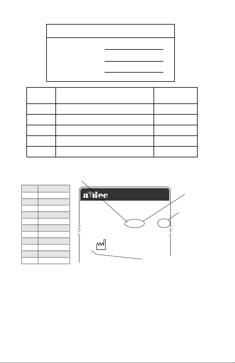
ALPHABETICAL EQUIVALENT
TO THE NUMERAL OF THE
MONTH MANUFACTURED
A January
B February
C March
D April
E May
F June
G July
H August
I September
J October
K November
L December
Model/Description of Service
Designated EU Representative: A-dec Dental U.K., Ltd.¤
Austin House, 11 Liberty Way, Attleborough Fields,¤
2601 CRESTVIEW DRIVE
NEWBERG, OREGON 97132 USA
Nuneaton, Warwickshire, England CV116RZ¤
Tele: (44) 24 7635 0901
1999
MADE ¤
IN USA
SN: J828287
REF: 2122
YEAR MANUFACTURED
Technician's
Initials
SERIAL
NUMBER
MODEL
NUMBER
SERIAL NUMBER IDENTIFICATION
Serial Number Location:
• 3181: On the bottom of the control head.
• 4631: On the control head housing.
• 4635: On the assistant’s instrumentation housing.
For service information contact your local authorized A-dec dealer.
Check with local codes and A.D.A. (Americans with Disabilities
Act) requirements for installation of this product.
Page 3

A-dec warrants its products and A-dec/W&H
handpieces against defects in material or workmanship
for one year from time of delivery. A-dec’s sole
obligation under the warranty is to provide parts for the
repair, or at its option, to provide the replacement
product (excluding labor). The buyer shall have no
other remedy. (All special, incidental, and coincidental
damages are excluded.) Written notice of breach of
warranty must be given to A-dec within the warranty
period. The warranty does not cover damage resulting
from improper installation or maintenance, accident or
misuse.The warranty does not cover damage resulting
from the use of cleaning, disinfecting or sterilization
chemicals and processes. The warranty also does not
cover light bulbs. Failure to follow instructions provided
in A-dec’s Operation and Maintenance Instructions
(Owner’s Guide) may void the warranty.
A-dec warrants A-dec dental chair cylinders, both lift
and tilt, for ten years from the date of purchase of
the chair or the cylinder. This warranty is retroactive
to A-dec chair cylinders already in the field. The
warranty covers chair cylinders A-dec finds to have
manufacturing related irregularities. Stool cylinders
are covered under A-dec‘s one-year warranty.
Warranty
NO OTHER WARRANTIES AS TO
MERCHANTABILITY OR OTHERWISE ARE MADE.
All product names used in this document are trademarks or
registered trademarks of their respective holders.
Printed in U.S.A. • Copyright © 2002 • All Rights Reserved
Page 4
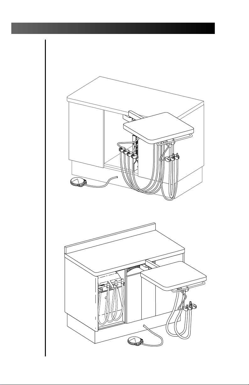
Cascade 3181 & A-dec 4631 Duo Delivery Systems
Serial number location, service information, and
warranty information are located on the inside
front cover and front page.
I
M
A
S
T
E
R
O
1
P
U
S
H
2
3
4
A-dec 4631 Duo Delivery System
Cascade 3181 Duo Delivery System
Page 5

Cascade 3181 & A-dec 4631 Duo Delivery Systems
CONTENTS
Handpiece Delivery System
Handpiece Actuation .............................. 2
Drive Air Pressure Gauge ........................ 2
Handpiece Controls ...................................... 3
Master On/Off Toggle.............................. 4
Drive Air Pressure Controls ..................... 5
Coolant Air Flow Control........................ 6
Coolant Water Flow Controls.................. 7
Handpiece Tubing Flush ......................... 8
Foot Control............................................. 9
Adjustments
Mounting Arm Tension Adjustments ... 10
Work Surface Repositioning .................. 11
Doctor’s/Assistant’s Instrumentation
Arm Tension Adjustments.................... 12
Holder Bar Tension Adjustments .......... 12
Handpiece Holder Tension Adjustment
& Positioning........................................ 13
Tray Holder Left/Right Conversion ....... 14
Handpiece Dry Block Conversion............... 15
Oil Collector ................................................ 16
Syringe......................................................... 17
Care Instructions............................................. 17
Assistant’s Instrumentation
Autoclavable HVE & Saliva Ejector.......... 18
Solids Collector.......................................... 18
Utility Area Controls and Functions .......... 19
Air Manual Shutoff Valve ..................... 19
Air-actuated Shutoff Valve.................... 19
Air Filter................................................. 20
Air Pressure Pre-Regulator..................... 20
Vacuum Outlet ...................................... 20
System Air Pressure Adjustment ................. 21
Filter Maintenance
Air Filter Element................................... 23
Maintenance................................................... 25
Adjustments and Specifications ..................... 26
Identification of Symbols................................ 27
Classification of Equipment (EN 60601-1)..... 27
1
Page 6
Cascade 3181 & A-dec 4631 Duo Delivery Systems
Handpiece Delivery System
Your delivery system is built around A-dec’s
Century Plus
®
Handpiece Actuation
Handpiece activation is automatic. When you lift
a handpiece from its holder the handpiece
becomes active and will run when you press on the
foot control disc (refer to page 9).
Figure 1. Handpiece Actuation
Drive Air Pressure Gauge
control system.
8
7
6
5
4
3
2
1
The drive air pressure gauge indicates, in psi
and kg/cm
2
, the drive air pressure to the
active handpiece.
I
M
A
ST
E
R
O
1
P
U
S
H
2
3
4
DRIVE AIR
PRESSURE
GAUGE
Figure 2. Drive Air Pressure Gauge
2
Page 7
Cascade 3181 & A-dec 4631 Duo Delivery Systems
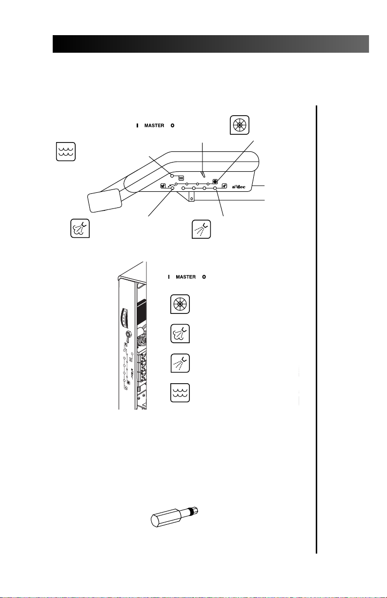
Handpiece Controls
CASCADE 3181
CONTROLS
HANDPIECE
FLUSH CONTROL
(see page 8)
COOLANT AIR
FLOW CONTROL
(see page 6)
A-DEC 4631
CONTROLS
MASTER
ON/OFF
TOGGLE
DRIVE AIR
PRESSURE
CONTROLS
(see page 4)
PUSH
I MASTER O
1234
®
COOLANT WATER
FLOW CONTROLS
(see page 7)
MASTER ON/OFF
TOGGLE
DRIVE AIR PRESSURE
CONTROLS (see page 4)
I M
A
ST
E
R
O
1
P
U
S
H
2
3
4
COOLANT AIR FLOW
CONTROL (see page 6)
COOLANT WATER FLOW
CONTROLS (see page 7)
HANDPIECE FLUSH
CONTROL (see page 8)
Figure 3. Handpiece Controls
Adjustment keys are provided for making
adjustments to the recessed controls. You can order
additional or replacement keys from your
authorized A-dec dealer, or use a 1⁄8" hex key.
Figure 4. Autoclavable Control Key
3
Page 8

Cascade 3181 & A-dec 4631 Duo Delivery Systems
Master On/Off Toggle
The master on/off toggle
(see Figure 3) turns air, water, and
electricity on or off to the system.
CAUTION
The MASTER ON/OFF TOGGLE should be
in the OFF (0) position whenever the unit
is not in use.
This will prevent the possibility of water
damage should a leak occur while the unit is
unattended.
Making sure the unit is off will also
prevent the possibility of self-activation
and the resulting burn-out of your
electrical accessories.
4
Page 9

Cascade 3181 & A-dec 4631 Duo Delivery Systems
Drive Air Pressure Controls
The drive air pressure controls (see Figure
3 on page 3) are used to adjust the drive
air pressure to each handpiece.
Adjust the drive air pressure to meet the handpiece
manufacturer’s dynamic drive air pressure
specification. Refer to the documentation that
came with your handpiece for the dynamic drive
air pressure specification.
Use a 3⁄32" hex key to complete this adjustment.
1. Install a bur in the handpiece.
2. Locate the drive air gauge on the front of the
control head (see Figure 2 on page 2).
3. Move the wet/dry toggle on the foot control
(see Figure 6 on page 9) to the OFF position,
away from the blue dot).
4. Turn the drive air control clockwise until the
valve seats.
5. Fully depress the foot control disc.
6. While running the handpiece, watch the
drive air gauge and adjust the handpiece
dynamic drive air pressure to meet
manufacturer’s specifications.
• Turn the drive air control counterclockwise to
increase drive air pressure flow.
• Turn the control clockwise to decrease flow.
NOTE
Do not turn the control counterclockwise
beyond the point where the drive air
pressure no longer increases. The control
adjustment screw may come completely out
of the unit.
7. Repeat steps 1 through 6 for each handpiece.
5
Page 10

Cascade 3181 & A-dec 4631 Duo Delivery Systems
Coolant Air Flow Control
The coolant air flow control (see Figure 3
on page 3) is used to adjust the coolant
air flow to all handpieces.
Use an adjustment key (see Figure 4 on page 3) or a
1⁄8" hex key to complete this adjustment.
1. Install a bur in the handpiece.
2. Locate the coolant air control
(see Figure 3 on page 3).
3. Move the wet/dry toggle on the foot control
(see Figure 6 on page 9) to the OFF position,
away from the blue dot.
4. Insert an adjustment key, or a 1⁄8" hex key,
into the coolant air flow control.
5. Fully depress the foot control disc to activate
the handpiece.
6. Adjust the coolant air flow to fit your needs.
A strong flow of air is recommended.
• Turn the control clockwise to decrease the flow.
• Turn counterclockwise to increase the flow.
7. The coolant air has been set for all handpieces.
6
Page 11

Cascade 3181 & A-dec 4631 Duo Delivery Systems
Coolant Water Flow Controls
The coolant water flow controls are used
to adjust the flow of coolant water to
each handpiece (see Figure 3 on page 3).
Use an adjustment key (see Figure 4 on page 3) or a
1⁄8" hex key to complete this adjustment.
1. Install a bur in the handpiece.
2. Locate the coolant water flow controls
(see Figure 3 on page 3).
3. Move the wet/dry toggle on the foot control
(see Figure 6 on page 9) to the ON position,
toward the blue dot.
4. Insert an adjustment key, or a 1⁄8" hex key,
into the coolant water flow control for the
handpiece being adjusted.
5. Hold the handpiece over a receptacle. Hold the
handpiece so that the water will be directed
away from you and into the receptacle.
Then fully depress the foot control disc to
activate the handpiece.
6. Adjust the coolant water flow to fit your needs.
• Turn the control clockwise to decrease the flow.
• Turn counterclockwise to increase the flow.
7. Adjust the coolant water for each handpiece.
7
Page 12

Cascade 3181 & A-dec 4631 Duo Delivery Systems
Handpiece Tubing Flush
The handpiece tubing flush system
flushes more water through the tubings
in less time than is normally possible
when operating only the foot control.
Disconnect the handpieces before
flushing the tubings.
After each patient, the handpiece tubing should
be flushed for about 20–30 seconds.
At the beginning of each day, the handpiece
tubing should be flushed for about 2–3 minutes.
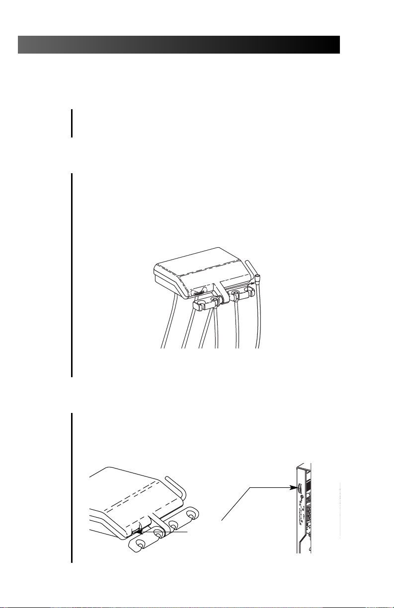
Flushing the Handpiece Tubings
Gather up all the handpiece tubings that use
coolant water and hold them over a sink, cuspidor
bowl or basin. Be sure you hold the tubings so that
the water will be directed away from you and into
the receptacle (see Figure 5).
Insert an adjustment key or 1⁄8" hex key into the
handpiece tubing flush control on the side of the
control head. Push in and hold the key for the
appropriate time required, either for flushing
between patients or flushing at the beginning of
each day, depending on the situation. Remove the
key and replace the tubings in their holders.
P
U
S
H
I
M
A
S
T
E
R
O
1
2
3
4
®
P
U
S
ADJUSTMENT
KEY
H
1
Figure 5. Handpiece Tubing Flush
8
Page 13

Cascade 3181 & A-dec 4631 Duo Delivery Systems
Foot Control
The foot control modulates drive air to the active
handpiece and provides an air signal that
activates the coolant air and coolant water flow.
The foot control is operated by light foot pressure
applied to any part of the foot control disc.
The foot control is equipped with a wet/dry toggle
and can be equipped with an optional chip blower
button (see Figure 6).
Wet/Dry Toggle. Allows you to shut off the
coolant water to the handpiece without moving
your hands from the oral cavity. Using your foot,
move the toggle away from the blue dot to turn
the coolant water OFF. Move the toggle toward the
blue dot to turn the coolant water ON.
Chip Blower Button. Sends a jet of air through
the handpiece when it is not running.
CHIP BLOWER
BUTTON
(Optional)
FOOT CONTROL DISC
WET/DRY TOGGLE
BLUE DOT
Figure 6. Foot Control
9
Page 14

Cascade 3181 & A-dec 4631 Duo Delivery Systems
Adjustments
Mounting Arm Tension Adjustments
The mounting arm for the work surface can be
adjusted to rotate at the desired resistance.
1. Using a 1⁄8" hex key, tighten or loosen the
three setscrews in the mounting arm.
TENSIONING
SETSCREWS
10
Figure 7. Arm tension adjustment
Page 15

Cascade 3181 & A-dec 4631 Duo Delivery Systems
Work Surface Repositioning
The work surface can be repositioned, thereby
maximizing space in the operatory.
1. Using a 1⁄8" hex key, remove the delivery
system assembly by removing the two front
screws and washers.
2. Remove the work surface from the mounting
arm by removing the two back screws
and washers.
3. Reposition the work surface to align with the
appropriate mounting holes.
4. Install the work surface to the mounting arm
using the two back screws and washers.
5. Install the delivery system assembly using the
two front screws and washers.
Figure 8. Arm tension adjustment
11
Page 16

Cascade 3181 & A-dec 4631 Duo Delivery Systems
Doctor’s/Assistant’s Instrumentation
Arm Tension Adjustments
The doctor’s or assistant’s instrumentation arms
can be adjusted to the desired resistance.
1. Using a wrench, tighten or loosen the
tensioning hex nut on the underside of the
doctor’s or assistant’s instrumentation housing.
TENSIONING
HEX NUT
Figure 9. Arm tension adjustment
Holder Bar Tension Adjustments
The doctor’s or assistant’s instrumentation holder
bar can be adjusted to the desired resistance.
1. Using a 5⁄32" hex key, tighten or loosen the
tensioning screw on the side of the doctors or
assistant’s instrumentation holder bar.
TENSIONING
SCREW
Figure 10. Arm tension adjustment
12
Page 17

Cascade 3181 & A-dec 4631 Duo Delivery Systems
Handpiece Holder Tension Adjustment & Positioning
The holder tension was set at the factory. However,
if a holder is difficult to reposition or repositions
too easily, the holder tension can be adjusted.
To adjust the holder tension:
• Loosening or tightening the tension adjustment
screw shown in Figures 11A and 11B.
To reposition a holder:
• Rotate the holder to the desired angle.
1/8"
HEX KEY
P
U
S
H
ROTATE THE HOLDER
FULL DOWN TO ACCESS
THE ADJUSTMENT SCREW
Figure 11A. Unitized Handpiece Holder
Figure 11B. Individual Handpiece Holder
13
Page 18

Cascade 3181 & A-dec 4631 Duo Delivery Systems
Tray Holder Left/Right Conversion
The optional tray holder can be easily mounted on
either side of the unit work surface.
LEFT-HAND
MOUNTING
LOCATION
TRAY HOLDER
(Shown mounted
for right-hand use.)
WORK SURFACE
Figure 12. Tray Holder Left/Right Conversion
14
1. Remove the plug from the work surface corner
opposite the current tray holder location.
2. Remove the tray holder from the unit’s work
surface and set aside.
3. Remove the brass tray holder bushing from the
work surface by removing the 9⁄16" hex nut
(located on the underside of the work surface)
that secures the bushing to the work surface.
4. Lift the brass bushing from its seat and move it
to the opposite side of the unit work surface.
5. Install the 9⁄16" hex nut to the new position
and tighten the hex nut.
6. Install the tray holder into the brass bushing.
7. Place the plug into the open tray holder hole.
Page 19

Cascade 3181 & A-dec 4631 Duo Delivery Systems
Handpiece Dry Block Conversion
The handpiece control system has one to four
handpiece control blocks with coolant water to the
handpiece. If you require a dry block (offering no
water to the handpiece) on your handpiece control
system, a dry block conversion kit has been
included with your system.
Installing the Dry Block Conversion Kit
1. Move the master on/off toggle to the OFF position. Bleed the system water by operating the
syringe and flushing the handpiece tubings.
2. Locate the handpiece control block position
that will be the dry block. Access the control
blocks underneath the control head.
3. Use a 3/32" hex key to remove the large red
cartridge from the control block. Install the
large black cartridge from the dry block conversion kit into the control block (see Figure 13).
4. Use a 3/32" hex key to remove the small blue
cartridge from the same control block. Install the
small black cartridge from the dry block conversion kit into the control block (see Figure 13).
5. Turn your handpiece control system on, then
check the function of the dry block handpiece
conversion. A small amount of residual water
may be discharged from the handpiece tubing
but should dry after a few seconds.
REMOVE AND REPLACE
THE RED CARTRIDGE
WITH THE LARGE BLACK
CARTRIDGE
DO NOT REMOVE
THE YELLOW
CARTRIDGE
Figure 13. Handpiece Dry Block Conversion
REMOVE AND REPLACE THE
BLUE CARTRIDGE WITH THE
SMALL BLACK CARTRIDGE
15
Page 20

Cascade 3181 & A-dec 4631 Duo Delivery Systems
Oil Collector
The oil collector gauze on your unit needs to be
changed once a week for normal usage. Change
more often for heavier use.
1. Remove the oil collector jar from the unit and
discard the old gauze (see Figure 14).
2. Fold in quarters a new two-inch square gauze
pad and place against the spring inside the jar.
3. Screw the oil collector jar onto the unit but do
not overtighten.
I
M
A
S
T
E
R
O
1
P
U
S
H
2
3
4
16
Figure 14. Oil Collector
Page 21

Cascade 3181 & A-dec 4631 Duo Delivery Systems
To operate the syringe:
• Move the on/off toggle to the ON position.
• Air – Press the right button down.
• Water – Press the left button down.
• Spray – Press both buttons down.
Syringe
AIR
Figure 15. Autoclavable Syringe
WATER
SPRAY
Refer to your Autoclavable Syringe Owner’s Guide
(A-dec Publication No. 85.0680.00) for complete
syringe operation and maintenance instructions.
Care Instructions
For recommended asepsis instructions, refer
to your Equipment Asepsis Owner’s Guide
(A-dec Publication No. 85.0696.00).
For recommended self-contained water system
care, refer to A-dec Self-contained Water System
Owner’s Guide (A-dec Publication No. 85.0675.00).
17
Page 22

Cascade 3181 & A-dec 4631 Duo Delivery Systems
Assistant’s Instrumentation
To operate the autoclavable HVE and saliva
ejector, simply turn the control valve.
The autoclavable HVE and saliva ejector can be
easily converted for right- or left-hand operation.
To convert, press the control valve out of the valve
body. Rotate the control valve 180°, then press it
back into the valve body.
CONTROL
VALVE
AUTOCLAVABLE
SALIVA EJECTOR
CONTROL
VALVE
AUTOCLAVABLE
HVE
Figure 16. Right- to Left-Hand Conversion
The solids collector prevents solids from entering
the central vacuum system.
HVE TUBING
ASSEMBLY
Figure 17. Solids Collector
SOLIDS
COLLECTOR
SCREEN
CAP
Refer to your Assistant’s Instrumentation
Owner's Guide (A-dec Publication No. 85.2610.00)
for more instructions.
18
Page 23

Cascade 3181 & A-dec 4631 Duo Delivery Systems
Utility Area Controls and Functions
To access the utility area, simply lift out the angled
lower cover located under the control head.
AIR MANUAL
SHUTOFF VALVE
FILTER
COVER
4
3
50
60
5
40
2
70
30
80
20
1
10
0
6
90
100
0
psi
7
2
kg/cm
AIR-ACTUATED
SHUTOFF VALVE
AIR PRE-REGULATOR
Figure 18. Air Controls
Air Manual Shutoff Valve
The air manual shutoff valve controls the air
supply to the unit. To prevent leaks, these valves
should remain fully open (turned counterclockwise) except while your unit is being serviced.
Air-actuated Shutoff Valve
The air-actuated shutoff valve automatically shuts
off air to the system when the master on/off toggle is
in the OFF position.
19
Page 24

Cascade 3181 & A-dec 4631 Duo Delivery Systems
Air Filter
The air filter prevents solids from entering the
unit. The procedures for checking and replacing the
filters are given on page 23.
Air Pressure Pre-Regulator
The air pressure pre-regulator controls the air
pressure in the unit. The procedure for adjusting
system pressure is given on page 21 and 22.
Vacuum Outlet
The office central Vacuum System Outlet is
located in the utility center. A flexible tube
connects your vacuum instruments to the outlet.
For information about your assistant’s vacuum
instruments, refer to Assistant’s Instrumentation
Owner’s Guide (A-dec Publication No. 85.2610.00).
20
Page 25

Cascade 3181 & A-dec 4631 Duo Delivery Systems
System Air Pressure Adjustments
The air pre-regulator is located in the utility
area inside the cabinet base. Before making
any adjustments, verify that the air compressor is turned on and that it maintains 80–100
psi (552–690 kPa) pressure in the tank. If it
doesn’t, refer to the compressor instructions.
1. Be sure that the manual shutoff valve is fully
open (counterclockwise). Turn the system ON,
and check the pressure gauge in the utility
area (see Figure 19). Air pressure should be
70–80 psi
(483–552 kPa)
2. While watching the gauge, operate the
syringe. If the system air pressure drops by
any more than 15 psi (103
clogged filters.
3. If adjustment of the air pressure is
required, turn the pre-regulator knob
clockwise to increase pressure, or
counterclockwise to decrease.
.
kPa
), check for
FILTER
COVER
AIR
PRESSURE
GAUGE
4
3
50
60
5
40
2
70
30
80
20
1
10
0
6
90
100
0
psi
7
2
kg/cm
AIR-ACTUATED
SHUTOFF VALVE
AIR PRE-REGULATOR
(pre-set to 80 psi [552 kPa])
Figure 19. Air Manual Shutoff Valve
21
Page 26

Cascade 3181 & A-dec 4631 Duo Delivery Systems
NOTE
When decreasing system air pressure, you
will not see the air gauge in the utility center
change until you relieve pressure from the
system. Activate the syringe for a few
seconds, then check the gauge. Repeat this
process each time you make an adjustment
to decrease pressure.
4. Test the unit by operating the syringe and
handpieces for several seconds. Make sure
the air pressure is maintained.
22
Page 27

Cascade 3181 & A-dec 4631 Duo Delivery Systems
Filter Maintenance
Air Filter Element
Air passes through a filter before entering the
regulator. A clogged filter can restrict flow to the
regulator and should be replaced immediately.
Checking for a Clogged Air Filter
To check for a clogged air filter, move the master
on/off toggle to the ON position, then remove the
utility area cover under the control head. While
watching the air pressure gauge in the utility area
(see Figure 20), press the syringe air button. If the
air pressure indicated by the gauge drops by more
than 15 psi (103 kPa), the filter element is clogged
and must be replaced.
FILTER
HOUSING
O-RING
(A-dec Part
No. 030.019.00)
Figure 20. Air Filter Replacement
FILTER ELEMENT
(A-dec Part No.
24.0234.01,Pkg of 6)
1
0
2
1
2
0
0
0
3
0
4
0
3
5
k
0
g
p
1
/
c
s
0
m
i
0
6
2
0
4
9
7
7
0
8
0
0
5
6
BEVELED EDGE
MANIFOLD
23
Page 28

Cascade 3181 & A-dec 4631 Duo Delivery Systems
Inspecting the Filter
To inspect or replace a filter element, move the
master on/off toggle to the OFF position, then close
the manual shutoff valve. Bleed the system of air
pressure by operating the syringe buttons. Using a
flat-blade screwdriver, remove the filter housing
from the air pre-regulator assembly (see Figure 20)
and remove the filter.
If the filter is visibly clogged or discolored,
replace it. Order A-dec Part No. 24.0234.00, or
24.0234.01 for a package of six.
When installing a new filter, notice that one end of
the filter has a beveled edge. Install the filter with
the beveled edge facing the manifold (see Figure
20). The system will not work properly if the filter is
installed incorrectly.
24
Page 29

Cascade 3181 & A-dec 4631 Duo Delivery Systems
Maintenance
Handpiece Controls
Handpiece Flush ..................................page 8
Oil Collector ........................................page 16
Utility Controls
System Air Pressure Adjustments ........page 21
Filter Maintenance
Air Filter Element ................................page 23
Also refer to the following A-dec documentation
for more maintenance information:
Autoclavable Syringe
Autoclavable Syringe
Owner’s Guide ..............................85.0680.00
Care Instructions
Equipment Asepsis
Owner’s Guide ..............................85.0696.00
Self-contained Water
Owner’s Guide ..............................85.0675.00
Power Supplies
Floor Boxes
Owner’s Guide ..............................85.2611.00
25
Page 30

Cascade 3181 & A-dec 4631 Duo Delivery Systems
Adjustments and Specifications
Handpiece Controls
Drive Air Pressure...............................page 5
(Refer also to your handpiece documentation for the
manufacturer’s dynamic drive air pressure specification.)
Coolant Air Flow ................................page 6
Coolant Water Flow ...........................page 7
Mounting Arm...................................page 10
Doctor’s/Assistant’s
Instrumentation Arm .......................page 12
Holder Bar ..........................................page 12
Handpiece Holder ..............................page 13
Service Requirements for Unit Operation:
Minimum Air:
2.50 cfm (70.80 L/min) at 80 psi (551 kPa)
Minimum Vacuum:
12 cfm (339.84 L/min)
at 8 inches of mercury (27 kPa)
26
Any optional non-A-dec attachments and/or accessories must comply with EN 60601-1 and EN
60601-1-2.
Weights of optional attachments:
Tooth Dryer: 1 lb (.45 kg)
Intra-oral Light Sources: 1 lb (.45 kg)
Curing Light: 3 lb (1.36 kg)
Specifications are subject to change without notice.
Page 31

®
LISTED
Cascade 3181 & A-dec 4631 Duo Delivery Systems
Identification of Symbols
Recognized by Underwriters Laboratories Inc. ® with respect to
electric shock, fire and mechanical hazards only in accordance
with UL 2601-1. Recognized with respect to electric shock, fire,
mechanical and other specified hazards only in accordance
with CAN/CSA C22.2, No. 601.1.
UL listed to US (UL 544) and Canadian (CAN/CSA C22.2,
No. 125) safety standards.
Classified by Underwriters Laboratories Inc. ® with respect to
electric shock, fire and mechanical hazards only in accordance
with UL 2601-1. Classified with respect to electric shock, fire,
mechanical and other specified hazards only in accordance
with CAN/CSA C22.2, No. 601.1.
Conforms to European Directives
Statement)
Protective earth (ground).
Functional earth (ground).
Attention, consult accompanying documents.
!
TYPE B APPLIED PART.
CLASS II EQUIPMENT.
(refer to Declaration
Classification of Equipment (EN 60601-1)
Type of shock protection:
CLASS I EQUIPMENT
(Dental Chairs, Dental Lights, & Power Supplies)
CLASS II EQUIPMENT
(Chair, Wall, & Cart Mounted Delivery Systems)
Degree of shock protection:
TYPE B APPLIED PART (All products)
Degree of protection against water ingress:
ORDINARY EQUIPMENT (All products)
Mode of operation
CONTINUOUS OPERATION
(All models except Dental Chairs)
Mode of operation
CONTINUOUS OPERATION
WITH INTERMITTENT LOADING (Dental Chairs)
27
Page 32

Cascade 3181 & A-dec 4631 Duo Delivery Systems
ENVIRONMENTAL
Storage - Temperature: -40°C to 70°C (-40°F to 158°F)
Relative Humidity: 95% maximum
Operating - Temperature: 10°C to 40°C (50°F to 104°F)
ELECTROMAGNETIC COMPATIBILITY
This equipment has been tested and found to comply with the
limits for medical devices in IEC 601-1-2:1994. These limits are
designed to provide reasonable protection against
harmful interference in a typical medical installation.
Contact A-dec Customer Service if you have any questions.
FLAMMABLE GASSES
Not suitable for use in the presence of a flammable anesthetic
mixture with air, oxygen, or nitrous oxide.
Relative Humidity: 95% maximum
28
Page 33

Cascade 3181 & A-dec 4631 Duo Delivery Systems
29
Page 34

Cascade 3181 & A-dec 4631 Duo Delivery Systems
30
Page 35

Cascade 3181 & A-dec 4631 Duo Delivery Systems
31
Page 36

USA and Canada
2601 Crestview Drive
Newberg, Oregon 97132 USA
Phone: 1-800-547-1883
1-503-538-7478
Fax: 1-503-538-0276
www.a-dec.com
International
Phone: 1-503-538-9471
Fax: 1-503-538-5911
Distribution Centers
A-dec Australia
41-43 Bowden Street
Alexandria, NSW 2015, Australia
Phone: 61-(0)2-9699 4600
Fax: 61-(0)2-9699 4700
www.adec.com.au
A-dec United Kingdom
Austin House
11 Liberty Way
Nuneaton, Warwickshire
England CV11 6RZ
Phone: 0800-ADEC-UK (2332-85) Within UK
44 24 7635 0901 Outside UK
Fax: 44 24 7634 5106
85.2643.00
2002-4 Rev B
(03597)
Made with recycled paper
Printed in USA.
Copyright © 2002
All Rights Reserved.
 Loading...