

Page 1
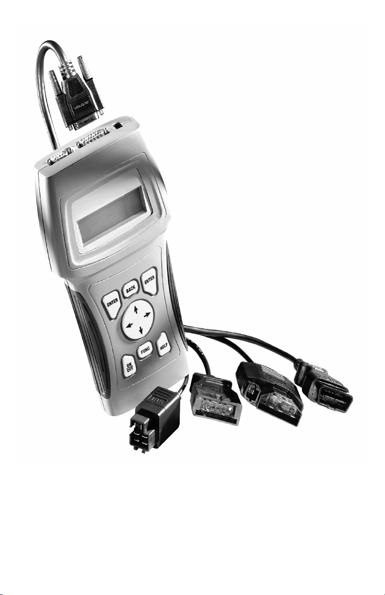
User’s Manual
9640B
Enhanced Scan Tool
Professional
Page 2

Scan Tool Information
Complete the following list using the
function “Tool Information”. Provide
this information when contacting
customer support.
Serial No:
SW ID:
HW Ver:
Boot Ver:
Prod ID:
Board ID:
Burn Date:
Burn Loc:
Copyright Information
Copyright © 2004 Actron Manufacturing, Inc.
All rights reserved.
The information, specifications and illustrations in this
manual are based on the latest information available at the
time of printing. Actron Manufacturing reserves the right
to make changes at any time without notice.
Page 3
Safety Precautions
For your safety, read this manual thoroughly before operating your Professional
Enhanced Scan Tool. Always refer to and follow safety messages and test
procedures provided by the manufacturer of the vehicle or equipment being
tested.
Your scan tool is intended for use by properly trained, skilled professional
automotive technicians. The safety messages presented below and throughout
this user’s manual are reminders to the operator to exercise extreme care when
using this test instrument.
Read All Instructions
Read, understand and follow all safety messages and instructions in this
manual and on the test equipment. Safety messages in this section of the
manual contain a signal word with a three-part message and, in some
instances, an icon. The signal word indicates the level of the hazard in a
situation.
Safety Messages
Safety messages are provided to help prevent personal injury and equipment
damage. All safety messages are introduced by a signal word indicating the
hazard level. The types of safety messages are:
DANGER
!
WARNING
!
Indicates an imminently hazardous situation which, if not
avoided, will result in death or serious injury to the operator
or to bystanders.
Indicates a potentially hazardous situation which, if not
avoided, could result in death or serious injury to the
operator or to bystanders.
!
Indicates a potentially hazardous situation which, if not
!
CAUTION
IMPORTANT
Safety messages contain three different type styles.
• Normal type states the hazard.
• Bold type states how to avoid the hazard.
• Italic type states the possible consequences of not avoiding the hazard.
An icon, when present, gives a graphical description of the potential hazard.
Example:
• • • • • • • • • • • • • • • • • • • • • • • • • • • • • • • • • • • • • • • • • • • • • • • • • • • • • • Safety – i
avoided, may result in moderate or minor injury to the
operator or to bystanders.
Indicates a situation which, if not avoided, may result in
damage to the test equipment or vehicle.
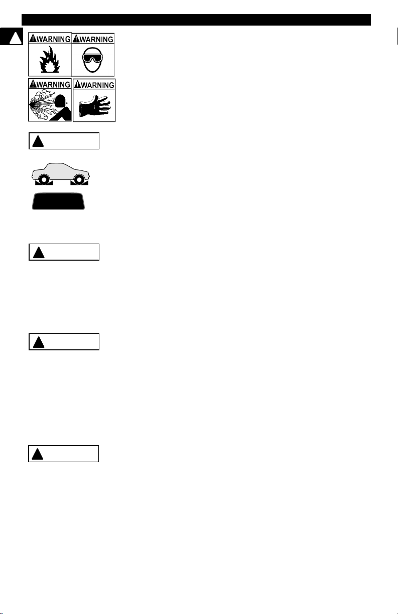
Engine systems can malfunction expelling fuel, oil vapors, hot
steam, hot toxic exhaust gases, acid, refrigerant and other
debris.
Wear safety goggles and protective gloves, user and
bystander. Everyday eyeglasses only have impact resistant
lenses, they are NOT safety glasses.
Engine systems that malfunction can cause injury.
Page 4
Safety Precautions
Important Safety Instructions
!
Risk of electric shock.
• Do not exceed voltage limits between inputs as indicated
in the “Specifications”.
• Use extreme caution when working with circuits that have
greater than 60 volts DC or 24 volts AC.
Electric shock can cause injury.
Risk of explosion.
• Wear safety goggles and protective clothing, user and
bystander. Everyday eyeglasses only have impact
resistant lenses, they are NOT safety glasses.
• Do not use this system in environments where explosive
vapor may collect, such as in below-ground pits, confined
areas, or areas that are less than 18 inches above the floor.
• Use this equipment in locations with mechanical
ventilation providing at least four air changes per hour.
• Flammable fuel and vapors can ignite.
• Do not smoke, strike a match, or cause a spark in the
vicinity of the battery. Battery gases can ignite.
• Avoid making accidental connection between battery
terminals. Do not place uninsulated metal tools on the
battery.
• When removing battery cables, remove ground cable first.
• Avoid sparks when connecting or disconnecting power
leads to battery.
• Be sure ignition is OFF, headlights and other accessories
are OFF and vehicle doors are closed before
disconnecting battery cables. This also helps prevent
damage to on-board computer systems.
• Always disconnect battery ground connections before
servicing electrical system components.
Explosion can cause injury.
WAR NI N G
!
!
WARNING
Risk of poisoning.
• Use this equipment in locations with mechanical
ventilation providing at least four air changes per hour.
Engine exhaust contains odorless lethal gas.
• Route exhaust outside while testing with engine running.
Poisoning can result in death or serious injury.
Battery acid is a highly corrosive sulfuric acid.
• Wear safety goggles and protective gloves, user and
bystander. Everyday eyeglasses only have impact
resistant lenses, they are NOT safety glasses.
• Make sure someone can hear you or is close enough to
provide aid when working near a battery.
• Have plenty of fresh water and soap nearby. If battery acid
contacts skin, clothing, or eyes, flush exposed area with
soap and water for 10 minutes.
• Seek medical help.
• Do not touch eyes while working near battery.
Battery acid can burn eyes and skin.
Risk of fire.
• Wear safety goggles and protective clothing, user and
bystander. Everyday eyeglasses only have impact
resistant lenses, they are NOT safety glasses.
Safety – ii • • • • • • • • • • • • • • • • • • • • • • • • • • • • • • • • • • • • • • • • • • • • • • • • • • • • •
Page 5
Safety Precautions
• Do not position head directly over or in front of throttle
body. Do not pour gasoline down throttle body when
cranking or running engine, when working with fuel
delivery systems or any open fuel line. Engine backfire
can occur when air cleaner is out of position.
• Do not use fuel injector cleaning solvents when
performing diagnostic testing.
• Keep cigarettes, sparks, open flame and other sources of
ignition away from vehicle.
• Keep a dry chemical (Class B) fire extinguisher rated for
gasoline, chemical and electrical fires in work area.
Fire can cause death or serious injury.
Risk of flying particles.
Wear safety goggles while using electrical equipment.
Electrical equipment or rotating engine parts can cause
flying particles.
Flying particles can cause eye injury.
Risk of burns.
Batteries can produce a short-circuit current high enough
to weld jewelry to metal. Remove jewelry such as rings,
bracelets and watches before working near batteries.
Short circuits can cause injury.
WARNING
!
Risk of burns.
• Do not remove radiator cap unless engine is cold.
Pressurized engine coolant may be hot.
• Do not touch hot exhaust systems, manifolds, engines,
radiators, sample probe, etc.
• Wear insulated gloves when handling hot engine
components.
• Tester leads can become hot after extended testing in
close proximity to manifolds etc.
Hot components can cause injury.
Risk of expelling fuel, oil vapors, hot steam, hot toxic exhaust
gases, acid, refrigerant and other debris.
• Wear safety goggles and protective clothing, user and
bystander. Everyday eyeglasses only have impact
resistant lenses, they are NOT safety glasses.
• Engine systems can malfunction expelling fuel, oil
vapors, hot steam, hot toxic exhaust gases, acid,
refrigerant and other debris.
Fuel, oil vapors, hot steam, hot toxic exhaust gases, acid,
refrigerant and other debris can cause serious injury.
The engine compartment contains electrical connections and
hot or moving parts.
• Keep yourself, test leads, clothing and other objects clear
of electrical connections and hot or moving engine parts.
• Do not wear watches, rings, or loose fitting clothing when
working in an engine compartment.
• Do not place test equipment or tools on fenders or other
places in the engine compartment.
• Barriers are recommended to help identify danger zones
in test area.
• Prevent personnel from walking through immediate test
area.
Contact with electrical connections and hot or moving parts
can cause injury.
• • • • • • • • • • • • • • • • • • • • • • • • • • • • • • • • • • • • • • • • • • • • • • • • • • • • • Safety – iii
!
Page 6
Safety Precautions
!
WARNING
!
PR ND L2
!
CAUTION
!
CAUTION
DANGER
!
Risk of injury.
• This equipment should be operated by qualified
personnel only.
• Use this equipment only as described in this manual. Use
only the manufacturer’s recommended attachments.
• Do not operate equipment with a damaged cord or if the
equipment has been dropped or damaged, until it has
been examined by a qualified service representative.
Operation of this equipment by anyone other than qualified
personnel may result in injury.
Risk of unexpected vehicle movement.
• Block drive wheels before performing a test with engine
running.
• Unless instructed otherwise, set parking brake and put
gear selector in neutral for standard transmissions or park
for automatic transmissions.
• If vehicle has an automatic parking brake release,
disconnect release mechanism for testing and reconnect
when testing is completed.
• Do not leave a running engine unattended.
A moving vehicle can cause injury.
Risk of equipment or circuit damage.
• Unless specifically directed by the manufacturer, make
sure the ignition is OFF before connecting or
disconnecting connectors or any vehicle electrical
terminals.
• Do not create a short between battery terminals with a
jumper wire or tools.
Improper equipment use can cause equipment or circuit
damage.
Misdiagnosis may lead to incorrect or improper repair and/or
adjustment.
Do not rely on erratic, questionable, or obviously erroneous
test information or results. If test information or results are
erratic, questionable, or obviously erroneous, make sure
that all connections and data entry information are correct
and that the test procedure was performed correctly. If test
information or results are still suspicious, do not use them
for diagnosis.
Improper repair and/or adjustment may cause vehicle or
equipment damage or unsafe operation.
Some vehicles are equipped with air bags. You must follow
vehicle service manual’s warnings when working around the
air bag components or wiring. If the service manual’s instructions are not followed, the air bag may open up unexpectedly,
resulting in personal injury. Note that the air bag can still open
up several minutes after the ignition key is off (or even if the
vehicle battery is disconnected) because of a special energy
reserve module.
Safety – iv • • • • • • • • • • • • • • • • • • • • • • • • • • • • • • • • • • • • • • • • • • • • • • • • • • • •
Page 7

Safety
!
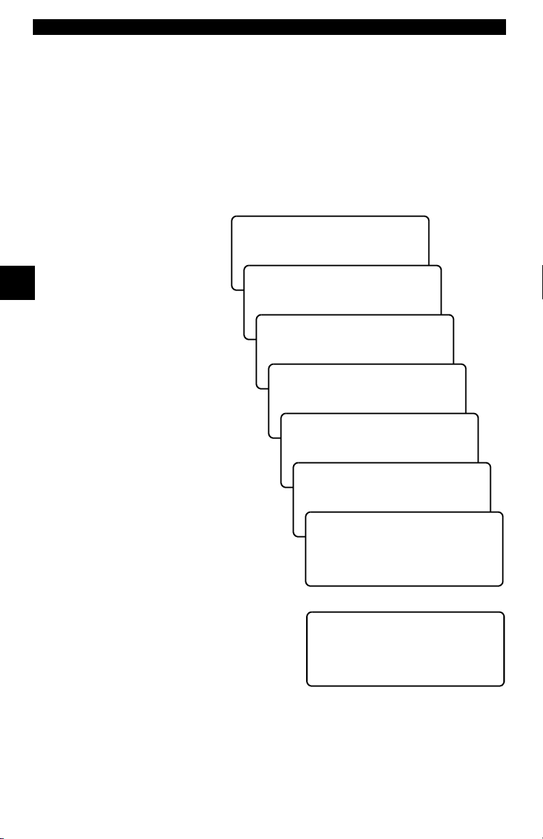
Table of Contents
Section 1 –––––––––– Using this Manual
Section 2 –––––––––––– Getting Started
Section 3 ––––––––Using The Scan Tool
Section 4 ––– Global OBD II Diagnostics
Section 5 –––––––––––– GM Diagnostics
Section 6 ––––––––––– Ford Diagnostics
1
2
3
4
5
6
ToC
Section 7 ––––––––Chrysler Diagnostics
Section 8 ––––– Help & Troubleshooting
Appendix A ––––– Data Link Connectors
Appendix B –––––––––––––––– Glossary
7
8
A
B
Page 8

Page 9

Section 1 – Using This Manual
This manual contains instructions for use and setup of your scan tool. A table
of contents and glossary are provided to make this manual easy to use.
Some of the information shown in text or illustrations is obtained using optional
equipment. A Sales Representative can determine option availability.
This section contains a list of conventions used.
Safety Messages
Refer to “Safety Precautions” on page i.
Check Note
A check note provides additional information about the subject in the preceding
paragraph.
Example:
✓ Make sure the printer is turned on, on-line and connected.
Equipment Tips and Lists
Equipment tips and lists provide information that applies to specific equipment.
Each tip is introduced by this icon
Example:
❒ Observe all vehicle and/or equipment manufacturer’s cautions and
warnings when testing with the scan tool.
❒ for easy identification.
1
Equipment Damage
Situations arise during testing that could damage the vehicle or the test
equipment. The word IMPORTANT signals these situations.
Example:
IMPORTANT
• • • • • • • • • • • • • • • • • • • • • • • • • • • • • • • • • • • • • • • • • • • • • • • • • • • • • • • • • 1 – 1
Failure to follow these instructions could damage the scan tool.
Page 10

Using This Manual
Functions and Selections
Diagnostic and tool functions performed by the scan tool are highlighted in bold.
Example:
The View Data function allows you to view the vehicle’s Parameter
Identification (PID) data in real time.
1
Menus
The menus on the scan tool display are referenced in the procedures and are
highlighted in bold-italic text.
Example:
When the OBDII Function List menu displays, the scan tool is ready for use.
Questions and Responses
Messages and user responses are CAPITALIZED.
Example:
The Scan Tool displays the Pending DTCs or a message stating SYSTEM
PASS: NO FAULT DETECTED.
Manual References
Used to reference other sections of the manual. References include the “Title”
and page number (section-page).
Example:
For more information on DTCs, refer to “Diagnostic Link Connectors (DLC)”
on page 2-4.
Screens
Certain Help messages, information, and data that are displayed on the scan
tool are also shown in graphical text boxes. The screens are presented as
examples and may change as the software is updated.
Example:
Main Menu ?
` Vehicle Diagnosis
Tool Setup [
Tool Self-Tests ~
1 – 2 • • • • • • • • • • • • • • • • • • • • • • • • • • • • • • • • • • • • • • • • • • • • • • • • • • • • • • • •
Page 11

Table of Contents
Safety Precautions
Section 1 – Using This Manual
Section 2 – Getting Started
Vehicle Service Information . . . . . . . . . . . . . . . . . . . . . . . . . . . . . . . . . . . . 2-1
Introduction to On-Board Diagnostics . . . . . . . . . . . . . . . . . . . . . . . . . . . 2-2
Diagnostic Link Connectors (DLC) . . . . . . . . . . . . . . . . . . . . . . . . . . . . . . 2-4
OBD II (J1962) . . . . . . . . . . . . . . . . . . . . . . . . . . . . . . . . . . . . . . . . . . . . 2-4
Ford Historic . . . . . . . . . . . . . . . . . . . . . . . . . . . . . . . . . . . . . . . . . . . . . . 2-5
GM Historic . . . . . . . . . . . . . . . . . . . . . . . . . . . . . . . . . . . . . . . . . . . . . . . 2-8
Chrysler Historic . . . . . . . . . . . . . . . . . . . . . . . . . . . . . . . . . . . . . . . . . . . 2-8
Diagnostic Trouble Codes (DTCs) . . . . . . . . . . . . . . . . . . . . . . . . . . . . . . . 2-9
Section 3 – Using The Scan Tool
The Scan Tool . . . . . . . . . . . . . . . . . . . . . . . . . . . . . . . . . . . . . . . . . . . . . . . 3-1
Specifications . . . . . . . . . . . . . . . . . . . . . . . . . . . . . . . . . . . . . . . . . . . . . 3-2
Accessories . . . . . . . . . . . . . . . . . . . . . . . . . . . . . . . . . . . . . . . . . . . . . . 3-2
Display . . . . . . . . . . . . . . . . . . . . . . . . . . . . . . . . . . . . . . . . . . . . . . . . . . 3-2
Keyboard . . . . . . . . . . . . . . . . . . . . . . . . . . . . . . . . . . . . . . . . . . . . . . . . 3-2
Power . . . . . . . . . . . . . . . . . . . . . . . . . . . . . . . . . . . . . . . . . . . . . . . . . . . 3-3
Scan Tool Setup . . . . . . . . . . . . . . . . . . . . . . . . . . . . . . . . . . . . . . . . . . . 3-4
Connecting The Scan Tool . . . . . . . . . . . . . . . . . . . . . . . . . . . . . . . . . . . . . 3-7
Vehicle Selection . . . . . . . . . . . . . . . . . . . . . . . . . . . . . . . . . . . . . . . . . . 3-7
Keep Current Vehicle . . . . . . . . . . . . . . . . . . . . . . . . . . . . . . . . . . . . . . . 3-7
Changing the Vehicle . . . . . . . . . . . . . . . . . . . . . . . . . . . . . . . . . . . . . . . 3-8
User Interface . . . . . . . . . . . . . . . . . . . . . . . . . . . . . . . . . . . . . . . . . . . . . 3-9
User Responses . . . . . . . . . . . . . . . . . . . . . . . . . . . . . . . . . . . . . . . . . . . 3-9
Viewing Data . . . . . . . . . . . . . . . . . . . . . . . . . . . . . . . . . . . . . . . . . . . . . . 3-9
ToC
Page 12

Section 4 – Global OBD II Diagnostics
Manual Info . . . . . . . . . . . . . . . . . . . . . . . . . . . . . . . . . . . . . . . . . . . . . . . . . . 4-1
I/M Readiness . . . . . . . . . . . . . . . . . . . . . . . . . . . . . . . . . . . . . . . . . . . . . . . . 4-1
Read Codes . . . . . . . . . . . . . . . . . . . . . . . . . . . . . . . . . . . . . . . . . . . . . . . . . 4-3
Pending Codes . . . . . . . . . . . . . . . . . . . . . . . . . . . . . . . . . . . . . . . . . . . . . . . 4-4
ToC
Erase Codes . . . . . . . . . . . . . . . . . . . . . . . . . . . . . . . . . . . . . . . . . . . . . . . . . 4-5
View Data . . . . . . . . . . . . . . . . . . . . . . . . . . . . . . . . . . . . . . . . . . . . . . . . . . . 4-6
View Freeze Data . . . . . . . . . . . . . . . . . . . . . . . . . . . . . . . . . . . . . . . . . . . . . 4-7
O2 Monitor Test . . . . . . . . . . . . . . . . . . . . . . . . . . . . . . . . . . . . . . . . . . . . . . 4-8
Diagnostic Monitor Tests . . . . . . . . . . . . . . . . . . . . . . . . . . . . . . . . . . . . . . 4-9
On-Board Systems . . . . . . . . . . . . . . . . . . . . . . . . . . . . . . . . . . . . . . . . . . . 4-11
Record Data . . . . . . . . . . . . . . . . . . . . . . . . . . . . . . . . . . . . . . . . . . . . . . . . 4-11
Vehicle Info . . . . . . . . . . . . . . . . . . . . . . . . . . . . . . . . . . . . . . . . . . . . . . . . . 4-13
Modules Present . . . . . . . . . . . . . . . . . . . . . . . . . . . . . . . . . . . . . . . . . . . . 4-14
Review Data . . . . . . . . . . . . . . . . . . . . . . . . . . . . . . . . . . . . . . . . . . . . . . . . 4-14
Playback . . . . . . . . . . . . . . . . . . . . . . . . . . . . . . . . . . . . . . . . . . . . . . . 4-14
Print Data . . . . . . . . . . . . . . . . . . . . . . . . . . . . . . . . . . . . . . . . . . . . . . . . . . 4-16
Printing Data (except Playback) . . . . . . . . . . . . . . . . . . . . . . . . . . . . . . 4-16
Printing Playback Data . . . . . . . . . . . . . . . . . . . . . . . . . . . . . . . . . . . . . 4-17
Code Lookup . . . . . . . . . . . . . . . . . . . . . . . . . . . . . . . . . . . . . . . . . . . . . . . 4-18
Section 5 – GM Diagnostics
GM Historic (OBD I) Diagnostics . . . . . . . . . . . . . . . . . . . . . . . . . . . . . . . . 5-1
Manual Info . . . . . . . . . . . . . . . . . . . . . . . . . . . . . . . . . . . . . . . . . . . . . . 5-1
Read Codes . . . . . . . . . . . . . . . . . . . . . . . . . . . . . . . . . . . . . . . . . . . . . . 5-1
Erase Codes . . . . . . . . . . . . . . . . . . . . . . . . . . . . . . . . . . . . . . . . . . . . . 5-2
View Data . . . . . . . . . . . . . . . . . . . . . . . . . . . . . . . . . . . . . . . . . . . . . . . . 5-4
Record Data . . . . . . . . . . . . . . . . . . . . . . . . . . . . . . . . . . . . . . . . . . . . . . 5-5
Review Data . . . . . . . . . . . . . . . . . . . . . . . . . . . . . . . . . . . . . . . . . . . . . . 5-6
Field Service . . . . . . . . . . . . . . . . . . . . . . . . . . . . . . . . . . . . . . . . . . . . . 5-8
Code Lookup . . . . . . . . . . . . . . . . . . . . . . . . . . . . . . . . . . . . . . . . . . . . 5-10
Print Data . . . . . . . . . . . . . . . . . . . . . . . . . . . . . . . . . . . . . . . . . . . . . . . 5-10
GM Enhanced (OBD II) Diagnostics . . . . . . . . . . . . . . . . . . . . . . . . . . . . . 5-11
Manual Info . . . . . . . . . . . . . . . . . . . . . . . . . . . . . . . . . . . . . . . . . . . . . 5-11
I/M Readiness . . . . . . . . . . . . . . . . . . . . . . . . . . . . . . . . . . . . . . . . . . . 5-11
Read Codes . . . . . . . . . . . . . . . . . . . . . . . . . . . . . . . . . . . . . . . . . . . . . 5-11
Pending Codes . . . . . . . . . . . . . . . . . . . . . . . . . . . . . . . . . . . . . . . . . . 5-13
Erase Codes . . . . . . . . . . . . . . . . . . . . . . . . . . . . . . . . . . . . . . . . . . . . 5-13
View Data . . . . . . . . . . . . . . . . . . . . . . . . . . . . . . . . . . . . . . . . . . . . . . . 5-13
View Freeze Data . . . . . . . . . . . . . . . . . . . . . . . . . . . . . . . . . . . . . . . . 5-15
O2 Monitor Test . . . . . . . . . . . . . . . . . . . . . . . . . . . . . . . . . . . . . . . . . . 5-15
Diagnostic Monitor Tests . . . . . . . . . . . . . . . . . . . . . . . . . . . . . . . . . . . 5-15
Record Data . . . . . . . . . . . . . . . . . . . . . . . . . . . . . . . . . . . . . . . . . . . . . 5-16
Vehicle Info . . . . . . . . . . . . . . . . . . . . . . . . . . . . . . . . . . . . . . . . . . . . . 5-16
Review Data . . . . . . . . . . . . . . . . . . . . . . . . . . . . . . . . . . . . . . . . . . . . . 5-16
Playback . . . . . . . . . . . . . . . . . . . . . . . . . . . . . . . . . . . . . . . . . . . . . . . 5-16
Print Data . . . . . . . . . . . . . . . . . . . . . . . . . . . . . . . . . . . . . . . . . . . . . . . 5-17
Code Lookup . . . . . . . . . . . . . . . . . . . . . . . . . . . . . . . . . . . . . . . . . . . . 5-17
ii
Page 13

Section 6 – Ford Diagnostics
Ford Historic Self-Test Routines . . . . . . . . . . . . . . . . . . . . . . . . . . . . . . . . 6-1
Manual Info . . . . . . . . . . . . . . . . . . . . . . . . . . . . . . . . . . . . . . . . . . . . . .. 6-1
Read KOEO Codes . . . . . . . . . . . . . . . . . . . . . . . . . . . . . . . . . . . . . . . .. 6-1
Read KOER Codes . . . . . . . . . . . . . . . . . . . . . . . . . . . . . . . . . . . . . . . .. 6-3
Review Codes . . . . . . . . . . . . . . . . . . . . . . . . . . . . . . . . . . . . . . . . . . . .. 6-6
Erase Codes . . . . . . . . . . . . . . . . . . . . . . . . . . . . . . . . . . . . . . . . . . . . .. 6-7
Wiggle Test (EEC-IV Vehicles) . . . . . . . . . . . . . . . . . . . . . . . . . . . . . . . . 6-8
Output Switch Test (EEC-IV Vehicles) . . . . . . . . . . . . . . . . . . . . . . . . . 6-10
Cylinder (Cyl) Balance Test (EEC-IV Vehicles) . . . . . . . . . . . . . . . . . .. 6-11
IVSC-Speed Ctrl (EEC-IV Vehicles) . . . . . . . . . . . . . . . . . . . . . . . . . .. 6-13
STAR Test Mode (EEC-IV, MECS and MCU Vehicles) . . . . . . . . . . . . 6-15
Code Lookup . . . . . . . . . . . . . . . . . . . . . . . . . . . . . . . . . . . . . . . . . . . . . 6-16
Print Data . . . . . . . . . . . . . . . . . . . . . . . . . . . . . . . . . . . . . . . . . . . . . . .. 6-17
DCL Data Functions (EEC-IV Vehicles) . . . . . . . . . . . . . . . . . . . . . . .. 6-17
Ford Enhanced (OBD II) Diagnostics . . . . . . . . . . . . . . . . . . . . . . . . . . . . 6-21
Manual Info . . . . . . . . . . . . . . . . . . . . . . . . . . . . . . . . . . . . . . . . . . . . .. 6-21
I/M Readiness . . . . . . . . . . . . . . . . . . . . . . . . . . . . . . . . . . . . . . . . . . .. 6-21
Read MIL DTC . . . . . . . . . . . . . . . . . . . . . . . . . . . . . . . . . . . . . . . . . . .. 6-21
Read All DTC . . . . . . . . . . . . . . . . . . . . . . . . . . . . . . . . . . . . . . . . . . . .. 6-22
Pending Codes . . . . . . . . . . . . . . . . . . . . . . . . . . . . . . . . . . . . . . . . . .. 6-22
Erase Codes . . . . . . . . . . . . . . . . . . . . . . . . . . . . . . . . . . . . . . . . . . . .. 6-23
View Data . . . . . . . . . . . . . . . . . . . . . . . . . . . . . . . . . . . . . . . . . . . . . .. 6-23
View Freeze Data . . . . . . . . . . . . . . . . . . . . . . . . . . . . . . . . . . . . . . . .. 6-24
Quick Tests . . . . . . . . . . . . . . . . . . . . . . . . . . . . . . . . . . . . . . . . . . . . .. 6-24
Quick Tests (7.3L Powerstroke Diesel Only) . . . . . . . . . . . . . . . . . . . . . 6-28
O2 Monitor Test . . . . . . . . . . . . . . . . . . . . . . . . . . . . . . . . . . . . . . . . . .. 6-32
Diagnostic Monitor Tests . . . . . . . . . . . . . . . . . . . . . . . . . . . . . . . . . . . . 6-32
On-Board Systems . . . . . . . . . . . . . . . . . . . . . . . . . . . . . . . . . . . . . . .. 6-32
Record Data . . . . . . . . . . . . . . . . . . . . . . . . . . . . . . . . . . . . . . . . . . . . . 6-32
Vehicle Info . . . . . . . . . . . . . . . . . . . . . . . . . . . . . . . . . . . . . . . . . . . . .. 6-32
Review Data . . . . . . . . . . . . . . . . . . . . . . . . . . . . . . . . . . . . . . . . . . . .. 6-32
Print Data . . . . . . . . . . . . . . . . . . . . . . . . . . . . . . . . . . . . . . . . . . . . . . .. 6-32
Code Lookup . . . . . . . . . . . . . . . . . . . . . . . . . . . . . . . . . . . . . . . . . . . . . 6-32
ToC
iii
Page 14

Section 7 – Chrysler Diagnostics
Manual Info . . . . . . . . . . . . . . . . . . . . . . . . . . . . . . . . . . . . . . . . . . . . . . . . . . 7-1
Read Codes . . . . . . . . . . . . . . . . . . . . . . . . . . . . . . . . . . . . . . . . . . . . . . . . . 7-1
Read Temporary Codes . . . . . . . . . . . . . . . . . . . . . . . . . . . . . . . . . . . . . . . . 7-2
Erase Codes . . . . . . . . . . . . . . . . . . . . . . . . . . . . . . . . . . . . . . . . . . . . . . . . . 7-3
ToC
View Data . . . . . . . . . . . . . . . . . . . . . . . . . . . . . . . . . . . . . . . . . . . . . . . . . . . 7-4
Freeze Frame . . . . . . . . . . . . . . . . . . . . . . . . . . . . . . . . . . . . . . . . . . . . . . . . 7-5
Record Data . . . . . . . . . . . . . . . . . . . . . . . . . . . . . . . . . . . . . . . . . . . . . . . . . 7-5
Switch Test . . . . . . . . . . . . . . . . . . . . . . . . . . . . . . . . . . . . . . . . . . . . . . . . . . 7-7
Actuator Test . . . . . . . . . . . . . . . . . . . . . . . . . . . . . . . . . . . . . . . . . . . . . . . . 7-8
Idle Speed Test . . . . . . . . . . . . . . . . . . . . . . . . . . . . . . . . . . . . . . . . . . . . . . . 7-9
Sensor Test . . . . . . . . . . . . . . . . . . . . . . . . . . . . . . . . . . . . . . . . . . . . . . . . . . 7-9
Controller Info . . . . . . . . . . . . . . . . . . . . . . . . . . . . . . . . . . . . . . . . . . . . . .. 710
Reset EMR Lamp . . . . . . . . . . . . . . . . . . . . . . . . . . . . . . . . . . . . . . . . . . . . 7-10
Set Basic Time . . . . . . . . . . . . . . . . . . . . . . . . . . . . . . . . . . . . . . . . . . . . . . 7-11
Review DATA . . . . . . . . . . . . . . . . . . . . . . . . . . . . . . . . . . . . . . . . . . . . . . . 7-12
Print Data . . . . . . . . . . . . . . . . . . . . . . . . . . . . . . . . . . . . . . . . . . . . . . . . . . 7-13
Code Lookup . . . . . . . . . . . . . . . . . . . . . . . . . . . . . . . . . . . . . . . . . . . . . . . 7-13
Section 8 – Help & Troubleshooting
How to Use On-Line Help . . . . . . . . . . . . . . . . . . . . . . . . . . . . . . . . . . . . . . 8-1
Scan Tool Does Not Power Up . . . . . . . . . . . . . . . . . . . . . . . . . . . . . . . . . . 8-1
Using Non-OBD II Adapter Cables . . . . . . . . . . . . . . . . . . . . . . . . . . . . 8-1
Using J1962 (OBD II) or Chrysler LH Adapter Cable . . . . . . . . . . . . . . . 8-1
Error Messages . . . . . . . . . . . . . . . . . . . . . . . . . . . . . . . . . . . . . . . . . . . . . . 8-2
Vehicle Communication Fault . . . . . . . . . . . . . . . . . . . . . . . . . . . . . . . . 8-2
Operating Error or Erroneous Data . . . . . . . . . . . . . . . . . . . . . . . . . . . . 8-2
Battery Replacement . . . . . . . . . . . . . . . . . . . . . . . . . . . . . . . . . . . . . . . . . . 8-3
Tool Self-Tests . . . . . . . . . . . . . . . . . . . . . . . . . . . . . . . . . . . . . . . . . . . . . . . 8-4
Display Test . . . . . . . . . . . . . . . . . . . . . . . . . . . . . . . . . . . . . . . . . . . . . . 8-4
Keyboard Test . . . . . . . . . . . . . . . . . . . . . . . . . . . . . . . . . . . . . . . . . . . . 8-4
Memory Test . . . . . . . . . . . . . . . . . . . . . . . . . . . . . . . . . . . . . . . . . . . . . 8-5
Printer Test . . . . . . . . . . . . . . . . . . . . . . . . . . . . . . . . . . . . . . . . . . . . . . 8-5
Program Mode . . . . . . . . . . . . . . . . . . . . . . . . . . . . . . . . . . . . . . . . . . . . . . . 8-6
Technical Support . . . . . . . . . . . . . . . . . . . . . . . . . . . . . . . . . . . . . . . . . . . . 8-6
Appendix A – Data Link Connectors
Appendix B – Glossary
iv
Page 15

Section 2 – Getting Started
The Professional Enhanced Scan Tool was developed by experts in the
automotive service industry to help diagnose vehicles and assist in
troubleshooting procedures. The tool monitors vehicle events and retrieves
codes from the vehicle computer’s memory to pinpoint problem areas.
All information, illustrations and specifications contained in this manual are
based on the latest information available from industry sources at the time of
publication. No warranty (expressed or implied) can be made for its accuracy
or completeness, nor is any responsibility assumed by the manufacturer or
anyone connected with it for loss or damages suffered through reliance on any
information contained in this manual or misuse of accompanying product. The
manufacturer reserves the right to make changes at any time to this manual or
accompanying product without obligation to notify any person or organization
of such changes.
VEHICLE SERVICE INFORMATION
The following is a list of publishers who have manuals containing electronic
engine control diagnostic information. Some manuals may be available at auto
parts stores or your local public library. For others, you need to write for
availability and pricing, specifying the make, model and year of your vehicle.
2
Chilton Book Company
Chilton Way
Radnor, PA 19089
Haynes Publications
861 Lawrence Drive
Newbury Park, CA 91320
Cordura Publications
Mitchell Manuals, Inc.
Post Office Box 26260
San Diego, CA 92126
Motoríst Auto Repair Manual
Hearst Company
250 W. 55th Street
New York, NY 10019
General Motors Corporation:
Buick, Cadillac, Chevrolet, GEO, GMC,
Oldsmobile, & Pontiac
Helm Incorporated
Post Office Box 07130
Detroit, MI 48207
• • • • • • • • • • • • • • • • • • • • • • • • • • • • • • • • • • • • • • • • • • • • • • • • • • • • • • • • • 2 – 1
Saturn:
Adistra Corporation
c/o Saturn Publications
101 Union St.
Post Office Box 1000
Plymouth, MI 48170
Ford Motor Company:
Ford, Lincoln, & Mercury
Ford Publication Department
Helm Incorporated
Post Office Box 07150
Detroit, MI 48207
Chrysler Corporation:
Chrysler, Plymouth, & Dodge
Chrysler Motors Service Training
26001 Lawrence Avenue
Center Line, MI 48015
Page 16

Getting Started
INTRODUCTION TO ON-BOARD DIAGNOSTICS
Suitable manuals have titles such as:
•“Electronic Engine Controls”
•“Fuel Injection and Feedback Carburetors”
•“Fuel Injection and Electronic Engine Controls”
•“Emissions Control Manual”
... or similar titles
The original on-board diagnostics (OBD I) lacked consistency in
communication and interface while allowing different interpretations amongst
vehicle manufacturers. Ford and Chrysler used different types of engine control
computers and data link connectors, and GM varied the trouble codes and
2
OBD II Control Module
*
engines.
communication protocols from year-to-year.
The tables below highlight changes for GM, Ford, and Chrysler. If this seems
confusing; don’t worry. Your tool makes it easy. Based on the VIN information
selected during Scan Tool setup, the processor is automatically recognized. All
you have to do is choose the correct adapter cable and jumper wires (if
necessary). Details on adapter cables and jumper wires may be found in
“Diagnostic Link Connectors (DLC)” on page 2-4
.
GM On-Board Diagnostics
System Years Description
Most vehicles used the 12-pin ALDL (Assembly Line Data Link)
OBD I Control Module
OBD II system is used on certain 1994-1995 vehicles equipped with a 2.2L, 2.3L, 3.8L, 4.3L or 5.7L
1981–1995
1994*-Present Complies with OBD II regulations and uses the J1962 DLC.
located under the dash on the driver side. Some 94-95 vehicles
used the 16-pin OBD II (J1962) data link connector (DLC), but
use the Historical application software. Refer to the vehicle’s
Vehicle Emission Control Information label.
Ford On-Board Diagnostics
System Long Name Years Description
MCU
Microprocessor Control Unit 1980 –1991
EEC-IV
* EEC-V OBD II system used in 1994-1995 vehicles equipped with a 3.8L or 4.6L engine.
Electronic Engine Control,
Fourth generation
Mazda Electronic Control
MECS
System
Electronic Engine Control,
EEC-V
Fifth generation
Powertrain Electronic
PTEC
Controller
1984 –1995
1988 –1995
1994* – present
2000 – present
Used in police vehicles, containing carbureted
engines. Uses the MCU DLC.
Most Ford vehicles equipped with North
American engines. Uses the EEC-IV DLC.
Vehicles equipped with Mazda-sourced engines.
Uses MECS 6-pin and 17-pin DLCs.
Complies with OBD II regulations and uses the
OBD II J1962 DLC.
Complies with OBD II regulations and uses the
OBD II J1962 DLC.
2 – 2 • • • • • • • • • • • • • • • • • • • • • • • • • • • • • • • • • • • • • • • • • • • • • • • • • • • • • • • •
Page 17

Getting Started
Chrysler On-Board Diagnostics
System Long Name Years Description
Single Module Engine
SMEC
Controller
Single Board Engine
SBEC
Controller
OBD II
OBD II Powertrain
PCM
Control Module
Jeep/Truck Engine
JTEC
Controller
* In 1989, the SBEC system was installed in selected vehicles with 3.0L V6 engines.
** Some vehicles in 1995 were equipped with the OBD II PCM.
1989–1990
1989*–1995
1995**– present
1996– present
Used a 6-pin Serial Communication Interface (SCI)
DLC and has bidirectional capability.
Used two types of DLCs: a 6-pin SCI and a 6-pin LH
series.
The first to allow a tool to reset the EMR light on trucks.
Complies with OBD II regulations and uses the OBD II
J1962 DLC.
Complies with OBD II regulations and uses the OBD II
J1962 DLC.
The JTEC system is used on light-duty trucks and
Jeeps
OBD II stands for On-Board Diagnostics version II. OBD II is a system that the
Society of Automotive Engineers (SAE) developed to standardize automotive
electronic diagnosis. Technicians now can use the same tool to test any OBD
II compliant vehicles without special adapters. The SAE established guidelines
that provide:
• a universal diagnostic test connector, called the data link connector (DLC),
with dedicated pin assignments.
• a standardized location for the DLC, visible under the dash on the driver’s
side.
• a standardized list of diagnostic trouble codes (DTCs) used by all
manufacturers.
• a standardized list of parameter identification (PID) data used by all
manufacturers.
• the ability of the vehicle system to record a freeze frame of the operating
conditions when a fault occurs.
• expanded diagnostic capabilities that records a code whenever a condition
occurs that effects vehicle emissions.
• the ability to clear stored codes from vehicle memory with the scan tool.
2
In addition, SAE has published hundreds of pages of text defining a standard
communications protocol that establishes the hardware, software, and circuit
parameters of OBD II systems. Unfortunately, vehicle manufacturers have
different interpretations of this standard communications protocol. As a result,
the generic OBD II communications scheme used will vary, depending on the
vehicle.
• • • • • • • • • • • • • • • • • • • • • • • • • • • • • • • • • • • • • • • • • • • • • • • • • • • • • • • • • 2 – 3
Page 18
Getting Started
SAE publishes recommendations, not laws, but the Environmental Protection
Agency (EPA) and California Air Resources Board (CARB) made many of
SAE’s recommendations legal requirements that vehicle manufacturers were
required to phase in over a three-year period. Beginning in 1994, vehicles with
a new engine management computer – about 10% of each manufacturers fleet
– were supposed to comply with OBD II standards. For 1995, OBD II systems
were to appear on about 40% of the new vehicles sold in the USA. Some of the
1994-1995 OBD II systems were not fully compliant, so the Government
granted waivers to give manufacturers time to fine-tune their systems.
Beginning in 1996, most of the new vehicles sold in the USA were fully OBD II
compliant.
DIAGNOSTIC LINK CONNECTORS (DLC)
2
The Data Link Connector (DLC) allows the scan tool to communicate with the
vehicle’s computer(s). Before OBD II, manufacturers used different data link
connectors to communicate with the vehicle. The proper DLC adapter cable
must be used to connect the tool to the vehicle. Also, the vehicle’s DLC may be
found in several different places and have many different configurations. The
following describes the DLCs used by Ford, GM and Chrysler. The DLC location
and types for domestic vehicles can be looked up in the charts in “Appendix
A - Data Link Connectors".
OBD II (J1962)
Beginning in 1996, vehicles sold in
the United States use the J1962
(OBD II) DLC, a term taken from a
physical and electrical specification
number assigned by SAE (J1962).
The DLC should be located under
the dashboard on the driver side of
the vehicle. If the DLC is not located under the dashboard as stated, a decal
describing its location should be attached to the dashboard in the area the DLC
should have been located.
Because the OBD II J1962 connector has power and ground, you only need a
single cable connection to the tool for both power and tool communications.
Attach the OBD II adapter cable to the extender cable, both supplied with the
tool, to connect the tool. Certain pins in the connector are reserved
2 – 4 • • • • • • • • • • • • • • • • • • • • • • • • • • • • • • • • • • • • • • • • • • • • • • • • • • • • • • • •
Page 19
Getting Started
.
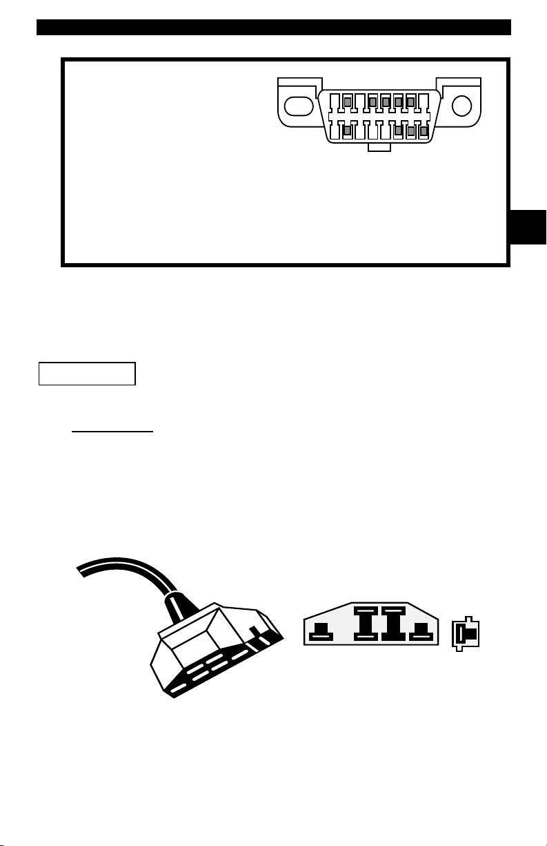
1 - Manufacturer Reserved
2 - J1850 Bus+
3 - Manufacturer Reserved
4 - Chassis Ground
5 - Signal Ground
6 - CAN High, J-2284
7 - K Line, ISO 9141-2 & ISO/DIS 14230-4
8 - Manufacturer Reserved
9 - Manufacturer Reserved
10 - J1850 Bus
11 - Manufacturer Reserved
12 - Manufacturer Reserved
Ford Historic
Ford used three types of DLCs with their historic (OBD I) systems. Refer to
“Appendix A - Data Link Connectors" for the adapter cable needed for your
vehicle.
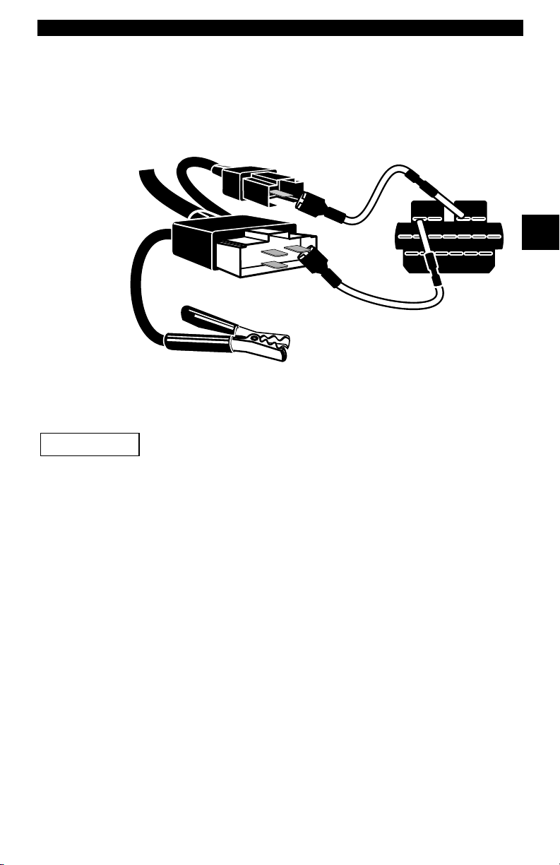
IMPORTANT
EEC-IV/MCU
The EEC-IV/MCU DLC is a large six-sided connector with a pigtail connector.
The pigtail connector is not used on MCU vehicles – leave the pigtail
unattached. The EEC-IV/MCU cable adapter is included with the scan tool.
Use the Battery Power cable to provide power to the scan tool
for all systems.
1
9
13 - Manufacturer Reserved
14 - CAN Low, J-2284
15 - L Line, ISO 9141-2 & ISO/DIS 14230-4
16 - Battery Power
8
16
2
Cable Adapter
EEC-IV/MCU
To Scan
Tool
Vehicle DLC
EEC-IV/MCU
STI Pigtail
EEC-IV
only
• • • • • • • • • • • • • • • • • • • • • • • • • • • • • • • • • • • • • • • • • • • • • • • • • • • • • • • • • 2 – 5
Page 20
Getting Started
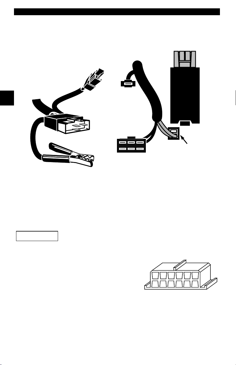
MECS
MECS vehicles (1988 –1995) use either a 6-pin (with pigtail) or a 17-pin DLC.
Use the MECS 6-pin adapter cable kit (P/N 9603) for both configurations. The
MECS adapter cable kit includes jumper wires to connect to the MECS 17-pin
DLC. The MECS adapter cable kit is not included with this tool. It is available
through your dealer. Use the following diagrams to connect the adapter cable.
6-Pin MECS
Cable Adapter
6-Pin MECS
P/N 9603
2
To Scan
To ol
STI Pigtail
6
5
4
3
2
1
Vehicle DLC
6-Pin MECS
Pigtail
Clip to good
Vehicle ground
2 – 6 • • • • • • • • • • • • • • • • • • • • • • • • • • • • • • • • • • • • • • • • • • • • • • • • • • • • • • • •
Page 21
Getting Started
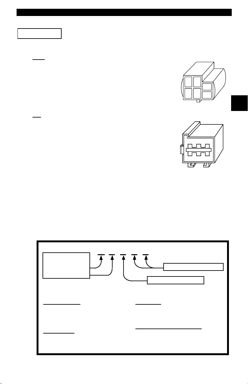
17-Pin MECS
Scan Tool
MECS Ford Probe
IMPORTANT
Adapter Cable
6-Pin MECS
To
P/N 9603
Vehicle DLC
17-Pin MECS
STI Pigtail
4
1
3
2
6
5
Clip to good
vehicle ground
Certain Ford Probes have a WHITE TACH CONNECTOR
located very close to the 6-pin Self-Test connector and
bundled in the same wiring harness. This is NOT the STI
(Self Test Input) Pigtail.
2
STO
Connect the pigtail to the BLACK STI connector located farther back on the wire
harness. If the tool is connected to the WHITE Tach connector, serious damage
may result and may void warranty. Refer to the illustration.
• • • • • • • • • • • • • • • • • • • • • • • • • • • • • • • • • • • • • • • • • • • • • • • • • • • • • • • • • 2 – 7
Page 22
Getting Started
Scan
2
Tool
GM Historic
IMPORTANT
To
Cable Adapter
6-Pin MECS
P/N 9603
STI
Pigtail
6
5
4
3
2
1
6-Pin MECS
BLACK STI
Connector
6-Pin MECS
Vehicle DLC
6-Pin MECS
Windshield
Wiper
Motor
WHITE
Tach
Connector
DO NOT USE!
Clip to good
vehicle ground
Prior to1996, most GM vehicles used the 12-pin Assembly Line Diagnostic Link
(ALDL) DLC. The GM ALDL cable kit includes the ALDL adapter and cigarette
lighter power cable. This adapter cable is included with the scan tool. In 1994
and 1995, certain GM vehicles use the J1962 (OBD II) DLC, but are not OBD
II compliant. Refer to “Appendix A - Data Link Connectors".
Use the Battery Power cable to provide 12V to the tool.
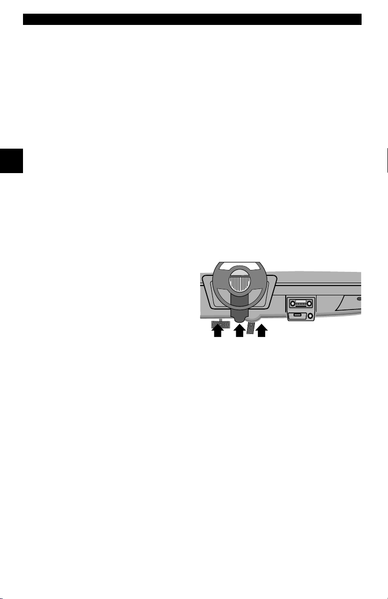
The ALDL DLCs are usually located under
the dashboard on the driver’s side.
ALDL
On Corvettes & Fieros, the DLC may be
located in the center console behind the
ashtray. Refer to vehicle service manual for
exact location. It may be in full view, or it
FGEHDJCKBLA
M
may be recessed behind a panel. An
opening in the panel should allow access to the recessed connector.
Chrysler Historic
Prior to 1996, most Chrysler vehicles used either the SCI or LH DLC. Refer to
“Appendix A - Data Link Connectors" for DLC type and location. The SCI
adapter cable is included with the scan tool. The LH adapter cable (P/N 9605)
can be purchased from your dealer.
2 – 8 • • • • • • • • • • • • • • • • • • • • • • • • • • • • • • • • • • • • • • • • • • • • • • • • • • • • • • • •
Page 23
Getting Started
IMPORTANT
Use the Battery Power cable to provide 12V to the tool when
using the SCI adapter cable.
SCI
The SCI (serial communications interface) DLC is a
6-pin connector located in the engine compartment.
The adapter cable to be used on these vehicles is
supplied with the tool. This cable is labeled CHRY on
the 15 pin DB style connector and SCI on the vehicle
end.
LH
LH (P/N 9605)
The DLC is used on LH platform vehicles. The LH
style DLC is a small, blue, rectangular 6-pin
connector located in the passenger compartment
below the dashboard to the right of the steering
column.
The LH Adapter Cable (P/N 9605) is optional and
must be purchased separately.
Diagnostic Trouble Codes (DTCs)
✓ Diagnostic Trouble Codes are used to help determine the cause of
a problem or problems with a vehicle.
SCI
2
❒ Diagnostic Trouble Codes (DTCs) consist of a five-digit
alphanumeric code.
The Diagnostic Trouble Codes format and general code types are shown below.
Bx - Body
Cx - Chassis
Px - Powertrain
Ux - Network Comm.
x = 0, 1, 2 or 3
Example:
P0101 - Mass or Volume Air Flow Circuit Range/Performance Problem
Powertrain Codes
P0xxx - Generic (SAE)
P1xxx - Manufacturer Specific
P2xxx - Generic (SAE)
P30xx-P33xx - Manufacturer Specific
P34xx-P39xx - Generic (SAE)
Chassis Codes
C0xxx - Generic (SAE)
C1xxx - Manufacturer Specific
C2xxx - Manufacturer Specific
C3xxx - Generic (SAE)
• • • • • • • • • • • • • • • • • • • • • • • • • • • • • • • • • • • • • • • • • • • • • • • • • • • • • • • • • 2 – 9
P 0 1 0 1
Body Codes
B0xxx - Generic (SAE)
B1xxx - Manufacturer Specific
B2xxx - Manufacturer Specific
B3xxx - Generic (SAE)
Network Communication Codes
U0xxx - Generic (SAE)
U1xxx - Manufacturer Specific
U2xxx - Manufacturer Specific
U3xxx - Generic (SAE)
Specific Fault Designation
Vehicle Specific System
Page 24
Getting Started
L
Assi
d DTC Syst
owerUpper
P0000 P00FF
P0100 P02FF
P0300 P03FF
P0400 P04FF
P0500 P05FF
P0600 P06FF
P0700 P09FF
2
P0A00 P0AFF
P1000 P10FF
P1100 P12FF
P1300 P13FF
P1400 P14FF
P1500 P15FF
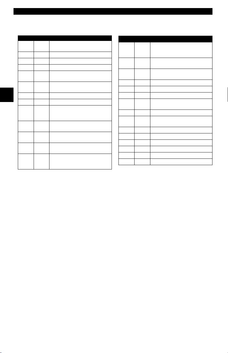
Within each general category, the DTCs are assigned to specific ranges that
cover certain vehicle systems.
gne
Fuel Air Metering Auxiliary
Emission Controls
Fuel Air Metering
Ignition System or Misfire
Auxiliary Emission Controls
Vehicle Speed Idle Control
Auxiliary Inputs
Computer and Auxiliary
Outputs
Transmission
Hybrid Propulsion
Manufacturer Control Fuel &
Air Metering, Auxiliary
Emission Controls
Manufacturer Control Fuel &
Air Metering
Manufacturer Control Ignition
System or Misfire
Manufacturer Control
Auxiliary emission Controls
Manufacturer Cntrl Veh.Spd.
Idle Speed Control Auxiliary
Inputs
em
Lower Upper Assigned DTC System
P1600 P16FF
P1700 P19FF
P2000 P22FF
P2300 P23FF
P2400 P24FF
P2500 P25FF
P2600 P26FF
P2700 P27FF
P2900 P32FF
P3300 P33FF
P3400 P34FF
U0000 U00FF
U0100 U02FF
U0300 U03FF
U0400 U04FF
Manufacturer Control
Auxiliary Inputs Auxiliary
Outputs
Manufacturer Control
Transmission
Fuel Air Metering Auxiliary
emission Controls
Ignition System or Misfire
Auxiliary Emission Controls
Auxiliary Inputs
Computer and Auxiliary
Outputs
Transmission
Fuel Air Metering Auxiliary
Emission Controls
Ignition System or
Cylinder Deactivation
Network Electrical
Network Communication
Network Software
Network Data
✓ J2012 and ISO 15031-6 are standards for all Diagnostic Trouble
Codes, established by the SAE, International Organization for
Standardization (ISO) and other governing bodies.
2 – 10 • • • • • • • • • • • • • • • • • • • • • • • • • • • • • • • • • • • • • • • • • • • • • • • • • • • • • • •
❒ Codes and definitions assigned by this specification are known as
Generic OBDII codes.
❒ OBDII requires compliance to this standard, for all cars, light
trucks, APVs, MPVs, and SUVs sold in the U.S.
Codes not reserved by the SAE are reserved for manufacturer and
referred to as Manufacturer Specific Codes.
Page 25
Section 3 – Using The Scan Tool
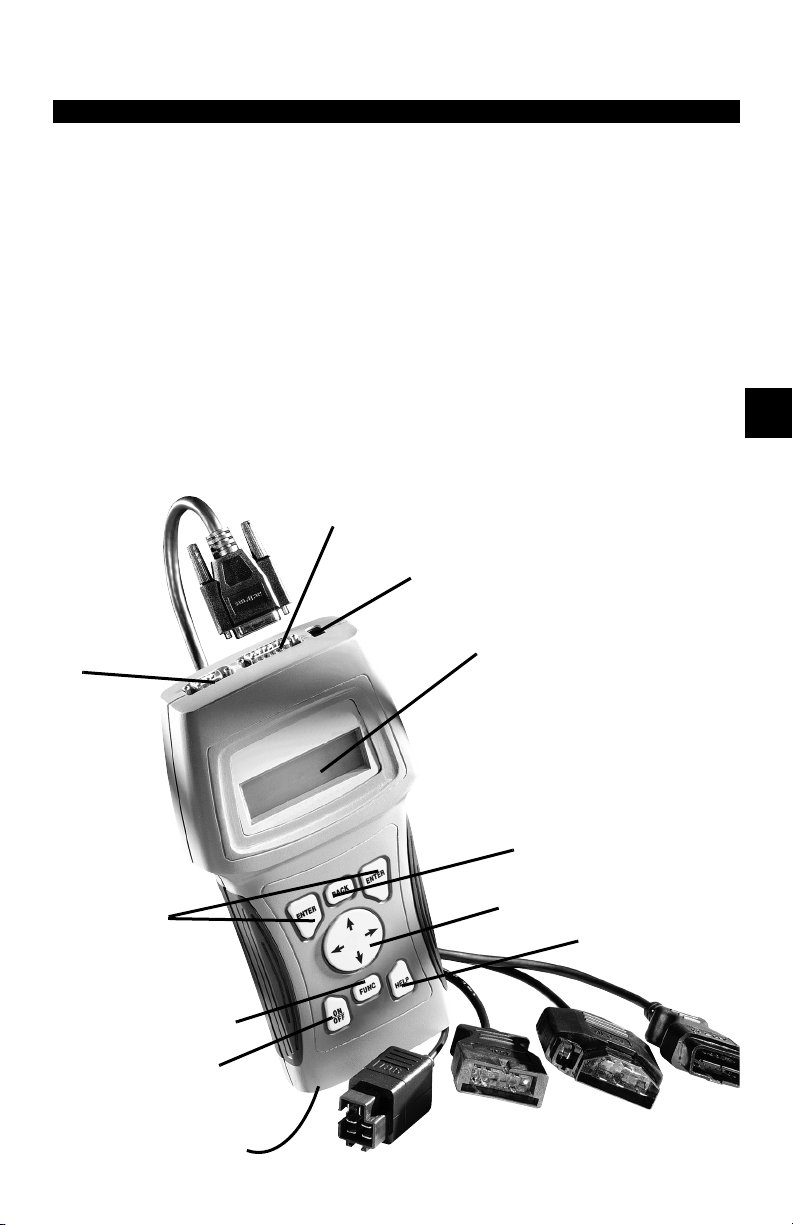
THE SCAN TOOL
B Serial Port (DB9 Male Connector) – provides a serial RS232 connection for a printer
and for updating the software.
C DLC Port (DB15 Male Connector) – provides connection for vehicle interface.
D 12V Power Jack
E LCD Display – backlit, 4 line x 20 character with contrast adjustment.
F
BACK
key – goes to the previous screen or level.
G
UP/DOWN
LEFT/RIGHT
H
HELP
I
ENTER
J
FUNC
a
ON/OFF
b Battery compartment cover.
B
arrows – scrolls UP or DOWN and moves the selection pointer (`).
arrows – selects responses and moves cursor (^) in code lookup.
key – accesses the Help Function.
key – selects displayed items.
key – returns back to a function list or menu.
key – turns power ON/OFF when not connected to vehicle.
C
D
E
3
F
I
G
H
j
a
b
• • • • • • • • • • • • • • • • • • • • • • • • • • • • • • • • • • • • • • • • • • • • • • • • • • • • • • • • • 3 – 1
Page 26

Using The Scan Tool
Specifications
Display: Backlit LCD, 4 line, 20 column, contrast adjust
Operating Temperature: 0 to 50°C (32 to 122°F)
Storage Temperature: -20 to 70°C (-4 to 158°F)
Internal Power: 6-AAA cells
External Power: 7 to 16 Volts
✓ Most vehicle control modules require at least 8.0 V to operate properly.
Power Dissipation: 3.5 Watts maximum
Dimensions: Height
1.625" 5.25" 9.75"
41 mm 133 mm 248 mm
Weight: 3.16 lbs (1432 g)
Accessories
3
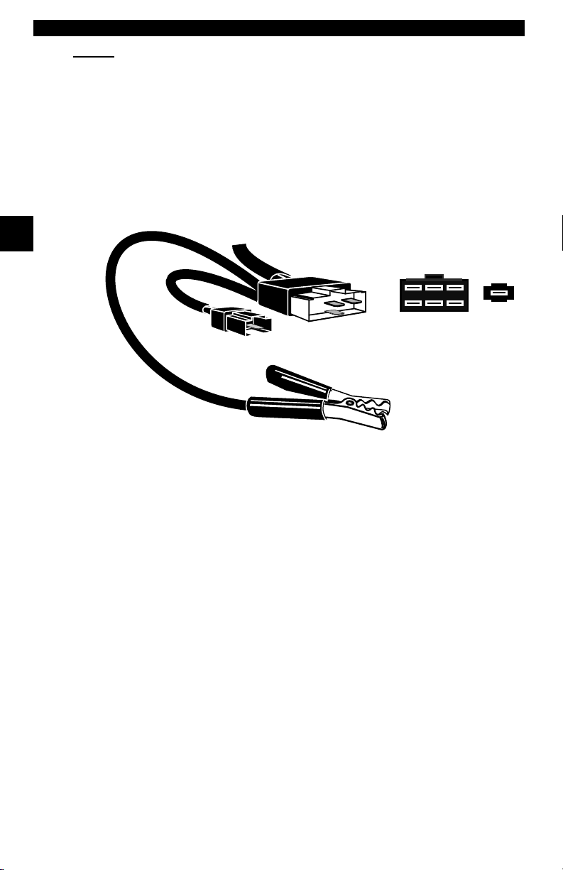
Standard 8 ft Extender Cable
Battery Power Cable (includes cigarette lighter adapter)
– included with adapter cable kits
– Battery Clip Adapter — Optional
Adapter Cables: Standard OBD II (J1962) cable — Included
GM ALDL cable kit — Included
Ford EEC-IV/MCU cable kit — Included
Chrysler SCI cable kit — Included
9605 Chrysler LH cable kit — Optional
9603 Ford Probe/MECS cable kit — Optional
Optional / Replacement Parts are available from the:
• dealer where you originally purchased your tool.
• manufacturer contact customer service at 1-800-228-7667 (8:00 – 6:00 EST
Monday – Friday) or send an email to tech_support@actron.com.
Display
The scan tool uses a 4 line by 20 character, back-lit Liquid Crystal Display
(LCD). The large viewing area displays messages, instructions, and diagnostic
information. The contrast can be adjusted.
Seven characters help you navigate and
operate the scan tool:
? appears in upper right corner of
display to indicate Help is available.
` identifies the selection.
[ indicates additional information is
available on the next screen.
] indicates additional information is available on the previous screen.
« identifies selected items in data lists.
~ Bell in lower right corner means the sound alert is on or active.
Low battery symbol will appear in bottom right-hand corner of the screen at
power-up if the internal batteries need replacement or are not installed.
Keyboard
The scan tool’s software is designed for ease in operating and navigating
through menus. Do not use solvents such as alcohol to clean the keypad or
display. Use a mild nonabrasive detergent and a soft cotton cloth. Do not soak
the keypad as water might find its way inside the scan tool.
3 – 2 • • • • • • • • • • • • • • • • • • • • • • • • • • • • • • • • • • • • • • • • • • • • • • • • • • • • • • • •
Width Length
Function List ?
` 2)Read DTC(Codes) ]
3)Erase DTC(Codes) [
4)View Data ~
Page 27
Using The Scan Tool
Power
✓ Refer to “Scan Tool Does Not Power Up” on page 8-1 if you encounter
problems.
Internal Batteries
When the scan tool is not connected to the vehicle, the
the scan tool. Press and hold down the
turn ON the scan tool.
To conserve battery power, the scan tool disables the display’s back-lighting
and turns OFF after a period of inactivity.
Each time the scan tool is powered up, the voltage of the batteries is checked.
If the voltage is low, the Low Battery Symbol () displays on the screen. Replace
batteries using the instructions provided in “Battery Replacement” on
page 8-3.
ON/OFF
ON/OFF
key for at least one second to
✓ If the scan tool will not be used for an extended period of time, remove the
batteries to prevent electrolyte leakage from damaging the battery
compartment.
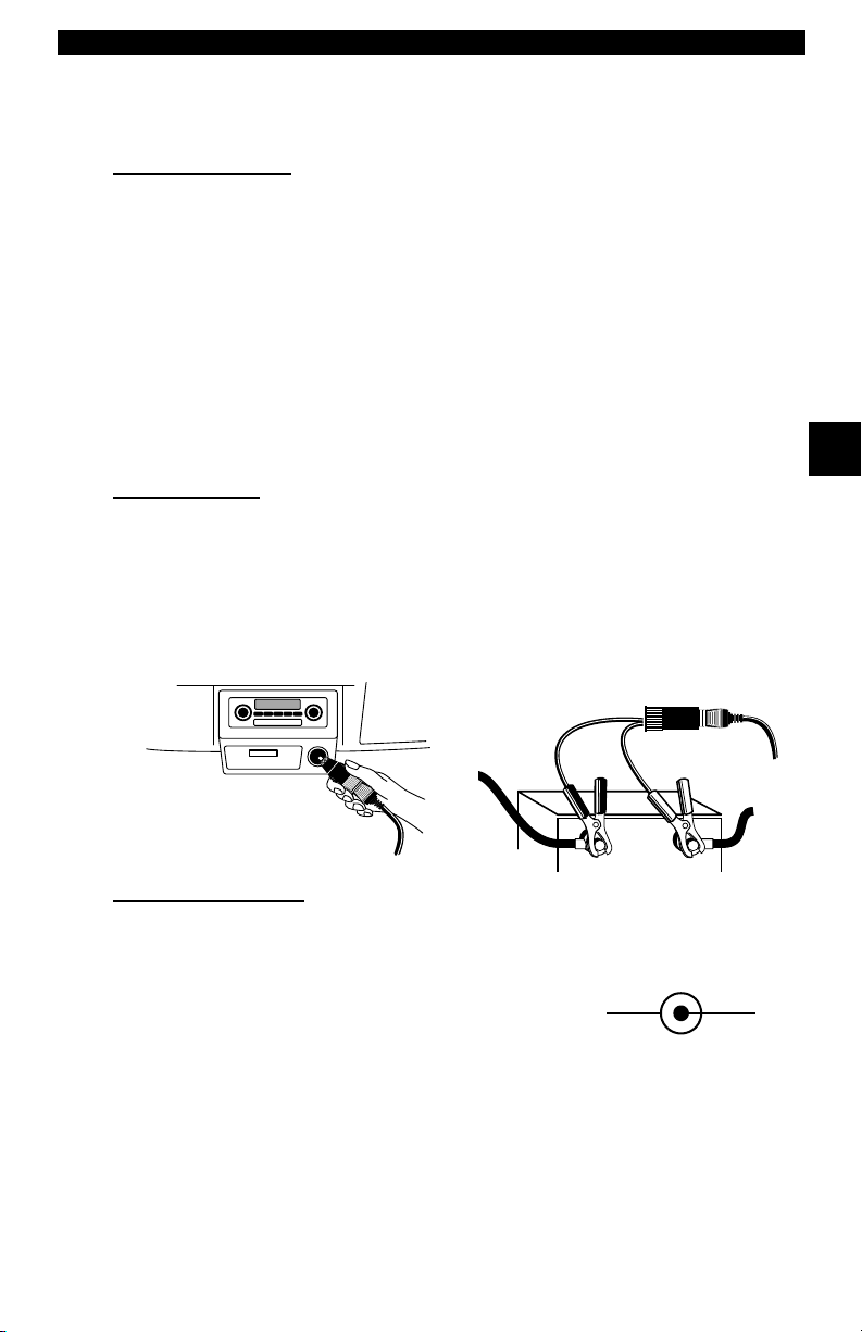
Vehicle Power
When using the OBD II J1962 or Chrysler LH adapter cables, the power to the
tool comes from vehicle Data Link Connector (DLC). All other vehicles will
require power connection to the cigarette lighter, accessory plug, or the vehicle
battery using battery clip adapters. If you are unsure of what DLC adapter to
use, then refer to “Appendix A - Data Link Connectors".
Some vehicle cigarette lighters are not powered when the ignition is in the OFF
position. Therefore, you may wish to use battery clip adapters.
Battery Clip Adapter (optional)
key turns ON
3
Cigarette Lighter Adapter
AC Power Adapter
An AC power adapter (not included) can be used to power the tool when
reprogramming from a personal computer or off-vehicle reviewing of codes and
printing. 12V AC-DC converters are available at most PC and electronic stores.
The tool is equipped to accept any 110 Vac - 12
Vdc wall adapter with the following specifications:
• 300 mA minimum current unregulated wall
power adapter.
• Adapter Dimensions: 5.5 mm Outside Diameter
• 2.5 mm Inside Diameter
• The Inside Tip is positive (+).
• • • • • • • • • • • • • • • • • • • • • • • • • • • • • • • • • • • • • • • • • • • • • • • • • • • • • • • • • 3 – 3
12 VGND
Page 28

Using The Scan Tool
Scan Tool Setup
Tool Setup allows you to change the
measurement units and LCD contrast,
turn beeper On/Off and display tool
information. The settings remain until
the internal batteries become
discharged.
Measurement Units
To change the measurement units, use
the
UP/DOWN
English/Metric and press
In the Measurement Units menu,
select English or Metric and then press
ENTER
Press
3
Changing Display Contrast
The display contrast can be adjusted
from the Tool Setup menu. Select
Display Contrast and press
Use the
increase and decrease the contrast.
Press
return to the Setup Tool menu.
Beeper
Beeper selection allows the user to turn Off the tool’s beeper. The bell symbol
~
will not appear in the lower right hand corner of the display when the beeper
is off.
Tool Information
This function allows you to view specific
tool information that may be needed when
contacting customer service.
Select Tool Information with the
UP/DOWN
The information shown to the right displays
on the screen. Use the
keys to view all the lines.
Press the
the Setup Tool menu.
✓ Write this information in the space provided on the inside of the front cover.
arrow keys to select
. English is the default.
ENTER
ENTER
again to return to the Setup Tool menu.
UP/DOWN
arrow keys and press
BACK
arrow keys to
to save the setting and to
UP/DOWN
or
ENTER
ENTER
key to return to
.
ENTER
ENTER
arrow
.
Main Menu ?
` Vehicle Diagnosis
Tool Setup [
Tool Self-Tests ~
Setup Tool
` 1)English/Metric
2)Display Contrast [
3)Beeper ~
] Increase Contrast
[ Decrease Contrast
Press ENTER To Save ~
Tool Information:
` Serial No:10000085
SW ID: 945BH
HW Ver: 0
Boot Ver: 0
.
Prod ID:3
Board ID: 10
Burn Date:03/07/02
3 – 4 • • • • • • • • • • • • • • • • • • • • • • • • • • • • • • • • • • • • • • • • • • • • • • • • • • • • • • • •
Page 29
Using The Scan Tool
Printer Interface
The scan tool is designed as a Data Terminal Equipment (DTE) device with a
DB9M (9-pin D-shape male) connector to interface with a compatible serial
printer.
Compatible Printers
The printer must have a serial RS-232 interface circuit and be compatible with
the Epson FX format. The following printers are recommended:
❒ Seiko DPU-414
❒ Kodak DICONIX 180si (serial printer model)
❒ Lexmark Model 2480 with optional serial interface (p/n 12T0154)
❒ Panasonic KX-P1131 printer
Cabling
❒ Type: A standard RS-232 type cable.
❒ Scan Tool end: DB9F (female) connector.
❒ Printer end:
• Use a DB9M (male) connector for the Seiko and
Kodak printers.
• Use a DB25 male connector for the Lexmark and
Panasonic printers.
• If the printer uses a different connector, then an
adapter or different RS-232 cable is required.
Adapters are available at most local PC stores or
electronics outlets.
Serial Port Settings
❒ Default settings for the scan tool are: 9600 Baud, 8 Data Bits, No Parity
and 1 Stop Bit.
❒ Ensure the settings on the scan tool and printer match.
❒ For the Lexmark and Panasonic printers, ensure the printer’s interface
selection is set to either “auto” or “serial”.
The printer and scan tool must have the same communication settings. You can
change the scan tool’s settings if necessary.
DB9
3
DB25
Changing the Printer Settings
Select either Print Codes from the
Main Menu or Print Data from of the
Function List and press
ENTER
.
Main Menu ?
Vehicle Diagnosis
` Print Codes [
Tool Setup
Next, the tool will inform you of the
printer settings (Custom or Default),
then ask if you wish to change them.
Select YES and press
default values are designated on the
display with the word (Default) next to
the option.
• • • • • • • • • • • • • • • • • • • • • • • • • • • • • • • • • • • • • • • • • • • • • • • • • • • • • • • • • 3 – 5
ENTER
.The
Tool Set To Default ?
Printer Settings.
Change Settings?
Yes <No>
Page 30
Using The Scan Tool
Refer to the printer manual for the settings. The changes made reside in the tool
even when the tool is turned off.
Tool settings are as follows. Defaults are in [ . . . ]
❒ Baud Rate: [9,600], 1200, 2400
❒ Stop Bits: [1 Bit], 2 bits
❒ Parity: [None], Odd, Even
❒ Printer Speed: [Fast], Slow
Press
the screens. For the printer to work properly, the tool and the printer must be set
to the same configuration. Change the settings accordingly.
To change the settings,
press the
and then
Use the
3
return to the previous
menu.
ENTER
LEFT
ENTER
BACK
after selecting each setting. Follow the instructions displayed on
arrow
.
key to
Select Baud Rate
` 9600(Defalut)
1200 [
2400
Select Data Bits
` 8 (Default)
The new printer settings
are tested by printing the
ASCII character set.
Press to continue.
Select Stop Bits
1 Bit(Default)
`2 Bits
Select Parity
` None (Default)
Make sure printer is
turned ON, ONLINE and
connected to the tool.
Press the
begin printing.
If the printout is not OK, then retry or
change settings. If it is, press
and the data transmits and prints.
ENTER
key to
ENTER
Odd
Even
Printer
` Fast (Default)
Slow
The ASCII Character
Set Will Be Printed
Once.
Press ENTER to Cont.
Test Ends By Itself
In Approximately 10
Seconds.
Press ENTER to Cont.
Make Sure Device
Is Turned On, Online
& Connected To Tool.
ENTER To Print
A printout of the test looks similar to the
example shown.
3 – 6 • • • • • • • • • • • • • • • • • • • • • • • • • • • • • • • • • • • • • • • • • • • • • • • • • • • • • • • •
-[ Print Test ]-
!"#$%&'()*+,-./01234
56789:;<=>?@ABCDEFGH
IJKLMNOPQRSTUVWXYZ[\
]^_`abcdefghijklmnop
qrstuvwxyz{|}~
Page 31

Using The Scan Tool
Diagnostic
Connector
CONNECTING THE SCAN TOOL
To diagnose a vehicle, connect the DLC and
power adapter (if applicable) to the scan tool.
Refer to “Diagnostic Link Connectors (DLC)”
on page 2-4 of Getting Started.
If you just want to power up the tool to do its
self-tests, code lookup, review or printing data
from the last vehicle tested, then you do not need
to attach the cable to the Data Link Connector. The internal battery provides
power for this.
When the scan tool powers up, a series
of messages display on the screen
beginning with a “Welcome” screen and
ending with a “Key Button Help” screen.
If you wish to review the key button
definitions, push the
otherwise, press
Vehicle Selection
When the tool powers up, the “Key Button Help” screen is followed by a Main
Menu screen.
Pick Vehicle Diagnosis to begin
Vehicle Selection. If there is a previous
vehicle present, the tool displays that
vehicle. You can choose the last vehicle
selected or setup for a new vehicle. The
tool retains all data retrieved from the
last vehicle selected until any of the
following occurs:
❒ A new vehicle is selected
❒ Internal AAA batteries are depleted or disconnected
❒ Tool is flash programmed to update software
❒ The last vehicle selected is kept but you choose Erase Data
You can either keep the previously
selected vehicle or change it. If
changing the vehicle, press the
arrow key and press
Otherwise, press
current one.
HELP
ENTER
ENTER
ENTER
key;
to continue.
RIGHT
.
to keep the
Main Menu ?
` Vehicle Diagnosis
<KEEP> CHANGE
Welcome To The
Professional
Enhanced Scan Tool
SW ID: XXXX
3
Tool Setup [
Tool Self-Tests ~
1995 Neon
C=2.0L SFI SOHC
Keep Current Vehicle
The next screen asks if you want to
erase the stored data. The default is
NO.
After pressing
displays.
• • • • • • • • • • • • • • • • • • • • • • • • • • • • • • • • • • • • • • • • • • • • • • • • • • • • • • • • • 3 – 7
ENTER
, the function list
Erase All Stored
Data For Selected
Vehicle?
YES <NO>
Page 32

Using The Scan Tool
Changing the Vehicle
Changing vehicles erases all data
stored in the tool. The default is YES.
Press
ENTER
Four Vehicle Options are available: General Motors, Ford, Chrysler and Global
OBD II. Global OBD II does not require additional information and takes you
directly to the function list. The other three require additional information so that
the tool can communicate with the vehicle. For example, select GENERAL
MOTORS.
The menus provide a list
of choices and reference
the vehicle’s VIN where
3
applicable. The VIN is
visible from outside the
vehicle by looking
through the base of the
front windshield at the top
of the dashboard on the
driver’s side. Because
manufacturers use
different VIN schemes,
the tool will indicate which
digit of the VIN to locate
for information such as
Year, Make and Engine.
Use
UP/DOWN
keys to move through the
list.
If you make a mistake,
press the
return to the previous
menu.
At the last screen, press
ENTER
BACK
.
to continue.
arrow
key to
Picking New Vehicle
Erases All Stored
Data. Continue?
<YES> NO
Select Manufacturer
` General Motors
Ford [
Chrysler
Select Vehicle Type
`Car
Truck
Select Year VIN 10
T=1996 ]
` S=1995 [
R=1994
Select Make VIN 3
3=Oldsmobile ]
` 4=Buick [
6=Cadillac
Select Model
Park Avenue ]
` Regal [
Reviera
Select Engine VIN 8
` L=3.8L SFI
M=3.1L SFI 4T60E
M=3.1L SFI AUTO-3S
1995 Regal
L=3.8L SFI
<KEEP> CHANGE
If a message displays, follow the
instructions then press
ENTER
.
Turn Key Off
For 10 Seconds
Then Turn Key On
Then Press ENTER
✓ Vehicles manufactured from 2000 to present automatically use Global OBD
II Diagnostics even if GM, Ford or Chrysler was selected.
3 – 8 • • • • • • • • • • • • • • • • • • • • • • • • • • • • • • • • • • • • • • • • • • • • • • • • • • • • • • • •
Page 33

Using The Scan Tool
User Interface
The scan tool is designed to be as intuitive as possible. All menu and lists
operate the same way. Use the
through the display or move the cursor (
ENTER
the
HELP
If a list or message contains more than four lines, an arrow icon displays on the
last column of the display to indicate the scrolling direction available: up (
down (
display. When the bottom of the list is reached, then only the
top of the list, only the
key to select the function or item. To return to previous screens, press
BACK
key after powering up the scan tool.
[). Use the
UP/DOWN
arrow keys to move
UP/DOWN
`) to a selectable item. Press the
key. This information can be viewed on the scan tool by pressing the
]) or
UP/DOWN
arrow keys to move line-by-line through the
] displays. At the
[ displays.
For example: to read DTCs stored in the
vehicle, move the cursor to Read
Codes with the
and press
choice, such as viewing data, use the
UP/DOWN
cursor down to View Data and press
ENTER
.
UP/DOWN
ENTER
. To make a different
arrow keys to move the
arrow keys
Function List ?
` 3)Erase DTC(Codes) ]
4)View Data [
5)View Freeze Data ~
User Responses
The scan tool may ask a question which
requires a YES or NO response —
brackets (<>) enclose the default one.
To accept the default choice, press the
ENTER
press the
move the brackets to another response and press
key. To change the answer,
LEFT/RIGHT
arrow keys to
View Instructions
For Creating Custom
Data List?
Yes <No> ~
ENTER
Viewing Data
Viewing data allows you to observe
sensor data and the operation of
switches, solenoids, and relays. As the
computer monitors the vehicle, the
parameter Identification (PID) data is
transmitted to the scan tool.
For viewing options, select View Data from the Function List and press
ENTER
.
Function List ?
3)Erase DTC(Codes) ]
` 4)View Data [
5)View Freeze Data ~
3
.
• • • • • • • • • • • • • • • • • • • • • • • • • • • • • • • • • • • • • • • • • • • • • • • • • • • • • • • • • 3 – 9
Page 34

Using The Scan Tool
Entire Data List
The Entire Data List shows all
supported parameter identification
(PID) data for the vehicle being tested.
When the scan tool makes a recording,
the data from all supported PIDs are
stored in the scan tool.
Select Data To View
` Entire Data List
Custom Data List
View Data Setup ~
Custom Data List
The Custom Data List allows you to
select certain PIDs from the Entire Data
List, such as those PIDs that pertain to
a specific driveability symptom or
system. The scan tool asks if you want
to view the instructions.
View Instructions
For Creating Custom
Data List?
YES <NO> ~
3
Once in the Custom Data List menu,
follow the instructions described below.
A
« symbol will be displayed next to all
selected PIDs. Use the
arrow keys to scroll through the list.
•Use the
•
UP
•
DOWN
RIGHT
•
values are marked with
•
LEFT
ENTER
•
data parameters.
UP/DOWN
arrow: Moves the cursor up the data list.
arrow: Moves the cursor down the data list.
arrow: Selects or deselects a data parameter. All selected data
arrow: Deselects all marked data parameters.
key: Starts playing back data, recording data, or displaying selected
UP/DOWN
arrow keys to move up and down through the list.
« symbol.
Select Custom List
« MIL STATUS
ABSLT TPS(%) [
` ENGINE(RPM) ~
Once in the Custom Data List selection screens, follow the instructions
described above to build a Custom Data List. Data parameters or Parameter
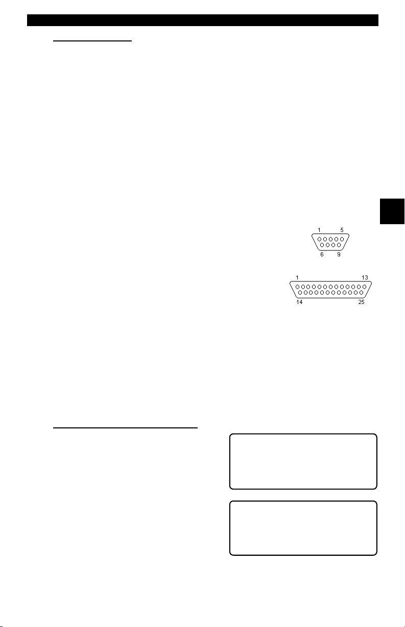
Identification Data (PID) will follow in alphabetical order.
When you are done selecting the PIDs, press the
PID values. Press the
menu.
BACK
key twice to return to the Select Data To View
View Data Setup
View Data Setup changes the number
of lines shown on the screen. Selecting
fewer lines provides faster update
speeds. The default is four-line display.
3 – 10 • • • • • • • • • • • • • • • • • • • • • • • • • • • • • • • • • • • • • • • • • • • • • • • • • • • • • • •
ENTER
Select Data To View
Entire Data List
Custom Data List
` View Data Setup ~
key to view selected
Page 35

Section 4 – Global OBDII Diagnostics
The first time scan tool links to the vehicle, communication is automatically
detected, and is used until scan tool is turned OFF or another vehicle is
diagnosed.
✓ If an Error Message displays, make sure OBDII connector is attached,
and ignition key is ON. Cycle ignition key to OFF for 10 seconds, then ON.
This may be required to reset computer. If required, select YES to try
again. If problem still exists, refer to “Error Messages” on page 8-2.
✓ On initial link to vehicle, Scan Tool checks status of I/M Monitors no
matter which function is selected.
MANUAL INFO
The Manual Info function, tells user what section of manual to use. This section
covers Global OBDII Diagnostics.
I/M READINESS
The I/M Readiness (Inspection and Maintenance) function displays state of
vehicle’s OBD II Monitors. Monitors are tests to verify operation of emission
related systems or components and detect out-of-range values. Vehicle may
have to be operated under certain driving conditions to initiate a monitor. If
vehicle loses electrical power or codes are erased, monitors may be cleared.
This function can be performed with key ON — engine OFF (KOEO) or key ON
— engine Running (KOER).
4
Abbreviations and names for OBDII Monitors supported by Scan Tool are
shown below. They are required by the U.S. Environmental Protection Agency
(EPA). Not all monitors are supported by all vehicles.
Abbreviated Name
Misfire Monitor ..............................Misfire Monitor
Fuel System Mon .........................Fuel System Monitor
Com Component ..........................Comprehensive Components Monitor
Catalyst Mon ................................Catalyst Monitor
Htd Catalyst..................................Heated Catalyst Monitor
Evap System Mon ........................Evaporative System Monitor
Sec Air System............................Secondary Air System Monitor
A/C Refrig Mon.............................Air Conditioning Refrigerant Monitor
Oxygen Sens Mon.......................Oxygen Sensor Monitor
Oxygen Sens Htr.........................Oxygen Heater Sensor Monitor
EGR System Mon ........................Exhaust Gas Recirculation System Monitor
• • • • • • • • • • • • • • • • • • • • • • • • • • • • • • • • • • • • • • • • • • • • • • • • • • • • • • • • • 4 – 1
Expanded Name
Page 36

Global OBDII Diagnostics
Vehicles may support two types of I/M Readiness:
❒ SINCE DTCs CLEARED shows monitor status since DTCs were erased.
❒ THIS DRIVING CYCLE shows monitor status since current drive cycle
started.
If monitors are not supported for THIS DRIVING CYCLE, Scan Tool only shows
monitors for SINCE DTCs CLEARED with no header on line 1.
Select I/M Readiness from OBDII
Function List menu and press
ENTER
OBDII Function List ?
.
1)I/M Readiness
2)Read Codes [
3)Pending Codes ~
Scan Tool displays message stating whether or not I/M Readiness monitors are
completed.
4
4
On-Board Readiness ?
Tests Are Complete
Not All Supported
On-Board Readiness
Tests Are Complete.
Use [ To View Test~
Use
DOWN
arrow key to view monitor statuses. If both monitor types are
supported, use
LEFT/RIGHT
arrow keys to toggle between monitor types.
THIS DRIVING CYCLE
Misfire Monitor n/a
Fuel System Mon ok [
Catalyst Mon inc ~
• A status of “OK” means required driving conditions for that monitor have
been met and monitor has ran to completion.
• A status of “Inc” means required driving conditions for that monitor have
not been met or monitor did not complete its cycle.
• A status of “N/A” means vehicle does not support that monitor.
Use [ To View ~
SINCE DTCS CLEARED
Misfire Monitor ok
Fuel System Mon ok [
Catalyst Mon inc~
When done, press
BACK
key to return to OBDII Function List.
4 – 2 • • • • • • • • • • • • • • • • • • • • • • • • • • • • • • • • • • • • • • • • • • • • • • • • • • • • • • • • •
Page 37

Global OBDII Diagnostics
READ CODES
The Read Codes function gets Diagnostic Trouble Codes (DTCs) from
vehicle’s computer module(s). Read Codes function can be done with Key On
Engine Off (KOEO) or Key On Engine Running (KOER).
These codes cause computer to light Malfunction Indicator Lamp (MIL) when
emission-related or driveability fault occurs. MIL is also known as “service
engine soon” or “check engine” lamp.
Select Read Codes and press
Scan Tool gets DTCs stored in vehicle’s
computer module(s).
ENTER
.
OBDII Function List ?
1)I/M Readiness
` 2)Read Codes [
3)Pending Codes ~
Scan Tool displays DTCs or a message stating SYSTEM PASS: NO CODES
FOUND. Scroll down to view DTCs or press
Function List.
System Pass:
No Faults Detected.
BACK
key to return to OBDII
DTCs Found: 1
Use [ To View DTCs
Write Down Codes
~
For Reference ~
P0107 Mod$10 1/1
MAP/BARO
Circuit Low Input [
~
Write down DTCs for reference and press
List.
BACK
to return to OBDII Function
4
• • • • • • • • • • • • • • • • • • • • • • • • • • • • • • • • • • • • • • • • • • • • • • • • • • • • • • • • • 4 – 3
Page 38

Global OBDII Diagnostics
PENDING CODES
Pending Codes are also referred to as “continuous monitor” and “maturing
codes”. An intermittent fault causes computer to store a code in memory. If fault
does not occur within 40 warm-up cycles, code clears from memory. If fault
occurs a specific number of times, code matures into a DTC and MIL lights or
blinks. This function can be done with KOEO or KOER.
Select Pending Codes and press
ENTER
key.
OBDII Function List ?
1)I/M Readiness
2)Read Codes [
` 3)Pending Codes ~
Scan Tool displays Pending DTCs or a message stating SYSTEM PASS: NO
FAULT DETECTED.
System Pass:
4
4
No Faults Detected.
~
Use
DOWN
arrow key to view DTCs or
BACK
press
Function List. If these tests show a
fault, DTCs display in same format as
Read Codes. Use
keys to view pending DTC(s).
Press
key to return to OBDII
UP/DOWN
BACK
key to return to OBDII Function List.
arrow
DTCs Found: 2
Use [ To View DTCs
Write Down Codes
For Reference ~
P0115 Mod$10 1/2
Engine Coolant Temp
Circuit Malfunction [
~
4 – 4 • • • • • • • • • • • • • • • • • • • • • • • • • • • • • • • • • • • • • • • • • • • • • • • • • • • • • • • • •
Page 39

Global OBDII Diagnostics
ERASE CODES
The Erase Codes function deletes DTCs from vehicle’s computer memory. It
may also erase Freeze Frame, O2 Sensor Data, System Monitors, and
On-Board Monitor test results. Perform this function only after systems have
been checked completely and DTCs have been documented. This function
should be performed with KOEO — Do not START engine.
After servicing vehicle, erase stored DTCs and verify no codes have been reset.
If DTCs return, problem has not been fixed or other faults are present.
✓ In addition to clearing DTCs, Erase Codes function may also erase
Freeze Frame, O2 Sensor Data, System Monitors, and On-Board Monitor
test results.
Select Erase Codes and press
key.
ENTER
OBDII Function List ?
` 4)Erase Codes ]
5)View Data [
6)View Freeze Data ~
Message appears asking if sure. Press
LEFT/RIGHT
brackets to response and press
ENTER
arrow keys to move
.
Erase Diagnostic
Results and Codes?
Are You Sure?
Yes <No> ~
Selecting NO displays a COMMAND CANCELLED message prompting to
press
ENTER
Selecting YES displays a screen
prompting to turn ignition KOEO, press
ENTER
to continue back to OBDII Function List.
key to continue.
Command Sent
Press ENTER To Cont~
4
ENTER
Scan Tool sends erase command. Press
OBDII Function List.
• • • • • • • • • • • • • • • • • • • • • • • • • • • • • • • • • • • • • • • • • • • • • • • • • • • • • • • • • 4 – 5
to continue and return to
Page 40

Global OBDII Diagnostics
VIEW DATA
The View Data function allows “real time” viewing of vehicle’s Parameter
Identification (PID) data. As computer monitors vehicle, information is
simultaneously transmitted to scan tool. Apart from Read Codes, View Data is
the most useful diagnostic function for isolating cause of a vehicle operation
problem. Viewing data is also used for observing sensor data and status of
switches, solenoids, and relays.
Select View Da ta from OBDII Function
List and press
ENTER
.
OBDII Function List ?
4)Erase Codes ]
` 5)View Data [
6)View Freeze Data ~
Scan tool asks vehicle to provide global
PIDs it supports.
4
4
Validating PID Map
PID23of99
Please Wait
After generating PID list, scan tool
displays menu with display options.
Use
UP/DOWN
ENTER
press
on page 3-9 to setup data list.
After making selection, press
Multiple PIDs may be sent if vehicle is equipped with more than one computer
module — Powertrain Control Module (PCM), Transmission Control Module
(TCM), etc. Scan tool identifies them by their identification names (ID) assigned
by manufacturer (i.e. $40 or $1F).
to select option and
. Refer to “Viewing Data”
ENTER
Select Data To View
` Entire Data List
Custom Data List
View Data Setup ~
to establish a communication link.
If Scan Tool receives multiple
responses for a PID, such as MIL
STATUS, Scan Tool displays PID and
with computer module ID blinking in
parentheses.
4 – 6 • • • • • • • • • • • • • • • • • • • • • • • • • • • • • • • • • • • • • • • • • • • • • • • • • • • • • • • • •
MIL STATUS($10) ON
MIL STATUS($1A) OFF
ENGINE($10) 256[
ENGINE($1A) 261 ~
Page 41

Global OBDII Diagnostics
If one or more control modules stops
responding, tool displays message that
it is not responding.
Module $1F is not
Responding. Continue
Without it?
Yes <No> ~
If choosen to continue, dashes will replace data in right-hand column. If NO is
selected, then scan tool attempts to reestablish communication with that
module.
Press
FUNC
to return to OBDII Function List.
VIEW FREEZE DATA
When an emission-related fault occurs, certain vehicle conditions are recorded
by the on-board computer. This information is referred to as Freeze Frame data.
The information is a “snapshot” of operating conditions at time of fault. This data
can be overwritten by faults with a higher priority.
✓ If codes were erased, then freeze frame data may not be stored in vehicle
memory.
4
Select View Freeze Data from OBDII
Function List and press
ENTER
.
OBDII Function List ?
4)Erase Codes ]
5)View Data [
`6)View Freeze Data ~
Scan tool links to vehicle, and verifies
PIDs and displays data. Use
UP/DOWN
list.
If more than one computer module
responds with freeze frame data, then
frame number and module display on
first line of Scan Tool. Press
LEFT/RIGHT
When done, press
• • • • • • • • • • • • • • • • • • • • • • • • • • • • • • • • • • • • • • • • • • • • • • • • • • • • • • • • • 4 – 7
arrow keys to move through
key to change modules.
BACK
key to return to OBDII Function List.
TROUB CODE P0443
ABSLT TPS(%) 36.5
CALC LOAD(%) 95.0[
COOLANT (oF) 120~
Frame 1 Mod $1A
TROUB CODE P044
ABSLT TPS(%) 36.5[
CALC LOAD(%) 95.0~
Page 42

Global OBDII Diagnostics
O2 MONITOR TEST
✓ The O2 Monitor Test is NOT AN ON-DEMAND TEST. O2 sensors are
NOT tested when selected via the menu. O2 sensors are tested when
engine operating conditions are within specified limits.
✓ If vehicle communicates using a Controller Area Network (CAN), O2
Monitor tests are NOT supported by vehicle. A message is displayed.
See Diagnostic Monitor Test to see O2 Monitor data.
OBDII regulations require applicable vehicles monitor and test oxygen (O2)
sensors to determine problems related to fuel and emissions. The O2 Monitor
Test allows retrieval of completed O2 sensors monitor test results.
O2 sensors are located before (upstream) and after (downstream) catalyst(s).
Sensors are named (xy) for their position to both cylinder banks and catalysts.
• The O2 sensor for cylinder bank 1 has prefix 1y while O2 sensor for cylinder
bank 2 has prefix 2y.
4
4
• The O2 sensor upstream of catalyst (closest to engine) has suffix x1 while
O2 sensor downstream of catalyst has suffix x2. If vehicle contains more
catalysts, O2 sensor downstream of second catalyst has suffix x3 and O2
sensor downstream of next catalyst has suffix x4.
• For example, O2S21 is upstream O2 sensor for cylinder bank 2.
The following O2 sensor tests are available:
1) Rich to Lean sensor threshold voltage
2) Lean to Rich sensor threshold voltage
3) Low sensor voltage for switch time
4) High sensor voltage for switch time
5) Rich to Lean sensor switch time
6) Lean to Rich sensor switch time
7) Minimum sensor voltage test cycle
8) Maximum sensor voltage test cycle
9) Time between sensor transitions
10) Sensor Period
Select O2 Monitor Test from OBDII
Function List and press
ENTER
.
OBDII Function List ?
`7)O2MonitorTest ]
8)Diag Mon Test [
9)On-Board Systems
4 – 8 • • • • • • • • • • • • • • • • • • • • • • • • • • • • • • • • • • • • • • • • • • • • • • • • • • • • • • • • •
~
Page 43

Global OBDII Diagnostics
Select desired test from menu and
ENTER
press
tests together makes data easier to
compare.
. Grouping O2 sensor
02 Sensor Tests
` 1)RICH-LN Thresh
2)LN-RICH Thresh
3)Lo V For Switch
✓ The O2 sensors located upstream (before catalyst) may perform
differently than ones located downstream (after catalyst).
[
~
Oxygen sensor tests that are not
supported by vehicle display three
dashes as value.
Press
BACK
to OBDII Function List.
key to return to O2 Sensor Tests menu or press
DIAGNOSTIC MONITOR TESTS
The Diagnostic Monitor Test function is useful after servicing or after erasing
vehicle’s memory. Test results do not necessarily indicate a faulty component
or system.
Non-CAN vehicles Diagnostic Monitor Tests receives test results for
emission-related powertrain components and systems not continuously
monitored.
CAN vehicles Diagnostic Monitor Tests receives test results for
emission-related powertrain components and systems that are or are not
continuously monitored.
Low Volts For Switch
O2S 11(V) 1.15
O2S 12(V) ---[
O2S 21(V) 1.28
FUNC
to return
~
4
✓
Vehicle manufacturer is responsible for assigning test and component IDs.
• • • • • • • • • • • • • • • • • • • • • • • • • • • • • • • • • • • • • • • • • • • • • • • • • • • • • • • • • 4 – 9
Page 44

Global OBDII Diagnostics
Select Diag Mon Test from OBDII
Function List and press
ENTER
.
OBDII Function List ?
7)O2 Monitor Test ]
` 8)Diag Mon Test [
9)On-Board Systems
~
Applicable tests are displayed . Select
a test and press
ENTER
.
Diag Mon Data Avail
`$01
$05 [
$10
~
Non-CAN Vehicles
OR
Diag Mon Data Avail
` O2 Sensor B1S1
Catalyst B1 [
4
4
EVAP (0.090)
~
CAN Vehicles
Requested test results are displayed
on Scan Tool
TEST $01
ID MEAS SPEC STS
74 8861 C000min Low[
76 3876 FFFFmax OK~
✓ On Non-CAN vehicles Scan Tool
displays:
❒ On the 1st line is where the test
data (test ID) came from.
❒ On the 2nd line is the test
performed
❒ On the 3rd and 4th line is the
test measurement (MEAS),
specification value (SPEC) and
status (STS). Measurements
and Specification values are
hexadecimal numbers (i.e., $1A,
$FE, $11.)
Non-CAN Vehicles
OR
O2 Sensor B1S1($00) ?
RICH-LN Thresh
0.5629(V) OK [
{O.5629, 0.5629}
CAN Vehicles
✓ On CAN vehicles Scan Tool displays:
❒ On the 1st line is where the monitor test data came from. For example
($00)represents the source module id from where the data originated.
❒ On the 2nd line is the test performed. The test performed can be $## if
test is not defined. Refer to vehicle service manual for details.
❒ On the 3rd line are the measured value and units measured in (Volts,
Amps, Seconds, etc.) and status of monitor test data.
❒
On the 4th line the low and high limits are shown for the monitor test data.
4 – 10 • • • • • • • • • • • • • • • • • • • • • • • • • • • • • • • • • • • • • • • • • • • • • • • • • • • • • • • •
Page 45

Global OBDII Diagnostics
If additional tests are present use
Refer to appropriate vehicle service manual for test IDs and definitions.
Press
BACK
key to return to the Diag Mon Test menu or press
return to OBDII Function List.
UP/DOWN
arrow keys to view test results.
ON-BOARD SYSTEMS
The On-Board Systems test allows scan tool to control operation of vehicle
components, tests or systems. Some manufacturers do not allow tools to
control vehicle systems. A vehicle not supporting an on-board system is
identified by a message displayed when selected.
✓ Refer to vehicle service manual for on-board systems instructions.
FUNC
key to
4
Select On-Board Systems from
OBDII Function List and press
ENTER
.
OBDII Function List ?
` 10)Record Data ]
11)Vehicle Info [
12)Modules Present ~
A list of on-board systems and
components available for testing display on screen.
Select a test and press
determining criteria to automatically stop test. Refer to appropriate vehicle
service manual.
ENTER
to activate test. Manufacturer is responsible for
RECORD DATA
The Record Data function records PIDs while vehicle is parked or being driven.
This function is mainly used for diagnosing intermittent driveability problems
that cannot be isolated by any other method.
Two people MUST be in vehicle when driving — one to
drive and the other to operate scan tool.
• • • • • • • • • • • • • • • • • • • • • • • • • • • • • • • • • • • • • • • • • • • • • • • • • • • • • • • • 4 – 11
Page 46

Global OBDII Diagnostics
Select Record Data from OBDII
Function List and press
Follow all instructions on display.
ENTER
.
OBDII Function List ?
` 10)Record Data ]
11)Vehicle Info [
12)Modules Present ~
Scan tool asks vehicle to provide global
PIDs vehicle supports.
Validating PID Map
PID23of99
Please Wait
✓ Scan tool can maintain only one recording per group. Make sure to
thoroughly review old recording before erasing.
4
4
If a recording currently exists in
memory, a message prompting to erase
data is displayed.
After list is generated, scan tool prompts to select type of data to record. Refer
to “Viewing Data” on page 3-9 to setup Entire or Custom Data Lists.
On next screen, select a triggering
method. Manual Trigger allows
technician to use
On Codes automatically triggers when
a DTC is indicated by vehicle.
ENTER
key. Tr igge r
Cannot Record. Old
Recording Filled Up
Memory. Erase Old?
YES <No>
Pick Trigger Method
`1)Manual Trigger
2)Trigger On Codes
~
Once trigger method is selected, scan tool will begin recording data. When
trigger event (either a DTC or a Press of
and data from last five frames are saved. Data will continue to be saved until
either record memory is full or technician presses
** INITIALIZING **
ENTER
key) occurs, time is recorded
ENTER
.
**Ready To Record**
Press ENTER Anytime
PRETRIG FRAME:-5
BACK To Exit ~
4 – 12 • • • • • • • • • • • • • • • • • • • • • • • • • • • • • • • • • • • • • • • • • • • • • • • • • • • • • • • •
To Start Recording.
Stops Automatically
~
Page 47

Global OBDII Diagnostics
Press
BACK
OBDII Function List.
key twice to return to
Waiting For Trouble
Code To Trigger The
Start of Recording
BACK To Exit
✓ Scan tool can maintain only one recording at a time. Make sure to
thoroughly review old recording before erasing.
~
Scan tool recording time varies. A
recording consists of 5 frames of data
prior to trigger and several frames after
trigger. The amount of PIDs recorded
determine number of frames.
After recording, Scan Tool displays a
prompt to playback recording. Answer
NO to return to OBDII Function List.
Answer YES to display recorded data. Refer to “Playback” on page 4-16 for
description of function.
VEHICLE INFO
The Vehicle Info function allows scan tool to request vehicle’s VIN number,
calibration ID(s) which uniquely identifies software version in vehicle control
module(s) and Calibration Verification Numbers (CVN(s).
This function applies to model year 2000 and newer OBDII compliant vehicles.
Scan tool cannot verify if data returned is correct for scanned vehicle. This
information is provided by vehicle manufacturer.
**Recording Data*
FRAME: 14 of 29
Press ENTER to Stop
Playback Data?
<YES> NO ~
~
4
Calibration Verification Numbers (CVNs) are calculated values required by OBDII
regulations. CVNs are reported to determine if emission-related calibrations have
been changed. Multiple CVNs may be reported for a control module.
✓ The calculation may take several minutes first time CVNs are requested.
• • • • • • • • • • • • • • • • • • • • • • • • • • • • • • • • • • • • • • • • • • • • • • • • • • • • • • • • 4 – 13
Page 48

Global OBDII Diagnostics
Select Vehicle In fo from OBDII
Function List and press
ENTER
.
OBDII Function List ?
10)Record Data ]
` 11)Vehicle Info [
12)Modules Present
~
Scan Tool displays VIN, Calibration ID,
and CVNs if supported by vehicle. In
following example, Module 10 returned
data. Scroll down to view information.
CVNs are shown as hexadecimal
number.
Cal ID # 1 MOD $10
GXAG20w.HEX ]
4
4
If message INVALID displays on screen, then data returned is incorrect, or not
formatted in accordance with OBDII specification. Press
to return to OBDII Function List.
MODULES PRESENT
The Scan Tool identifies the module IDs and communication type
for OBDII modules in the vehicle.
Select Modules Present
from the OBDII Function
List and press
ENTER
VIN # 1 MOD $10
1F1FS11P0S2100001
[
~
Cal Ver # 1 MOD $10
D4 5B 01 5D ]
[
~
BACK
or
ENTER
~
key
OBDII Function List ?
.
10)Record Data ]
1 1)Vehicle Info [
`12)Modules Present
✓Types of Protocols (communication types) supported by
Scan tool are:
4 – 14 • • • • • • • • • • • • • • • • • • • • • • • • • • • • • • • • • • • • • • • • • • • • • • • • • • • • • • • •
Page 49

Global OBDII Diagnostics
•ISO 9141-2 protocol will be shown as ISO
ID Protocols
$41 ISO*
$40 ISO*
•SAE J1850 protocol will be shown as VPWM OR PWM
ID Protocols
$10 VPWM*
OR
ID Protocols
$10 PWM*
•ISO 15765-4 protocol will be shown as CAN.
4
ID Protocols
$01 CAN*7e9
$00 CAN*7e8
NOTE: Since CAN vehicles use module ID’s larger
than 2 digits, the Scan Tool will assign a 2 digit module
ID to be used in place of the actual CAN module ID.
The Module ID assigned for the CAN Module ID will be
used in all functions of Scan Tool.
•ISO 14230-4 protocol will be shown as K2K (Keyword
2000.)
ID Protocols
$10 K2K*
$1A K2K*
• • • • • • • • • • • • • • • • • • • • • • • • • • • • • • • • • • • • • • • • • • • • • • • • • • • • • • • • 4 – 15
Page 50

Global OBDII Diagnostics
REVIEW DATA
The Review Data function allows operator to review information stored in Scan
Tool’s memory. Scan tool does not require power from vehicle to do this
function. Internal battery power can be used.
Select Review Data from OBDII
Function List and press
ENTER
.
OBDII Function List ?
` 13)Review Data ]
14)Print Data [
15)Code Lookup
Scan tool displays Review Data screen with nine types of data to review.
1) I/M Readiness
2) DTC (Codes)
3) Pending Codes
4) Freeze Frame
4
4
5) O2 Monitor
Most of the functions displayed on Review Data screen are self explanatory.
Only one function, Playback, needs detailed instructions. Follow prompts and
instructions provided by scan tool.
If data does not exist for function
selected to review (for example Vehicle
Info), a message informs to run
function first.
6) Diagnostic Monitor Test
7) Playback
8) Vehicle Info
9) Modules Present
No Data Stored In
Tool. Use VEHICLE
INFO Before
Reviewing.
~
~
Playback
The Playback function is used to play
back a recording. This function is very
similar to View Data. The only
difference is that View Data is real time
viewing of PIDs, while Playback is a
viewing of previously recorded PIDs.
To play back vehicle’s recorded PIDs, select Playback from Review Data list
and press
4 – 16 • • • • • • • • • • • • • • • • • • • • • • • • • • • • • • • • • • • • • • • • • • • • • • • • • • • • • • • •
ENTER
key to continue.
Review Data
`7)Playback ]
8)Vehicle Info
9)Modules Present
~
Page 51

Global OBDII Diagnostics
Scan tool displays a NO RECORDING PRESENT message if recording does
not exist. Otherwise, press
Entire Data List or Custom Data List, depending on how data was recorded.
ENTER
to play back recording. Scan tool plays back
The Playback has three lines of data
and one line for frame number and
timestamp (in seconds).
MIL STATUS($10) ON
MIL STATUS($1A) ON
ABSLT TPS(%)($10) 35[
FRAME: 1 TM: 4.4
Negative frames and timestamps indicate data recorded before trigger event.
Positive frames and timestamps indicate data recorded after trigger event.
Use
UP/DOWN
of list is reached when only
Use
LEFT/RIGHT
RIGHT
arrow key goes to next frame, “wrapping around” to earliest frame when
final frame is reached,
“wrapping around” to final frame.
arrow keys to view recorded PID data of each frame. The end
] (up) icon is visible.
arrow keys to scroll back and forth through frames. The
LEFT
arrow key goes back to previous frame, again
✓ Different vehicles communicate at different speeds and support a different
number of PIDs. Therefore, maximum number of frames that can be
recorded will vary.
✓ Some vehicles wait a long period of time to store a trouble code after
driveability problem occurs. If operator selected “Trigger On Codes” when
making recording, operator might not see any drastic change in data
parameters before and after trigger point. In cases like this, user can
manually trigger recording when symptoms are observed.
~
4
When done, press
• • • • • • • • • • • • • • • • • • • • • • • • • • • • • • • • • • • • • • • • • • • • • • • • • • • • • • • • 4 – 17
BACK
to return to Review Data or OBDII Function List.
Page 52

Global OBDII Diagnostics
PRINT DATA
The Print Data function allows the
printing of diagnostic information stored
in Scan Tool.
The scan tool’s internal battery power can be used to print data.
OBDII Function List ?
13)Review Data ]
` 14)Print Data [
15)Code Lookup
~
Select Print Data and press
key. Scan tool informs of printer settings
(Custom or Default), then asks if setting
need to be changed.
ENTER
Tool Set To Default ?
Printer Settings.
Change Settings?
YES <NO> ~
4
4
To change settings, refer to “Printer Interface” on page 3-5 of Using The Scan
Too l. Select NO and press
If printout is OK, select YES and press
ENTER
manual if printout is not OK.
. Refer to settings in printer
ENTER
key to begin printing.
Is Printout OK?
<YES> NO ~
4 – 18 • • • • • • • • • • • • • • • • • • • • • • • • • • • • • • • • • • • • • • • • • • • • • • • • • • • • • • • •
Page 53

Global OBDII Diagnostics
Printing Data (except Playback)
Select data to be printed and press
ENTER. Scan tool displays menu of
functions that store data and can be
printed.
✓ Make sure printer is turned on, on-line and connected.
When selected data does not exist in scan tool’s memory, a message informs
to run function.
Select Print Data
` 1)I/M Readiness
2)Read Codes [
3)Pending Codes
~
If selected data is stored in scan tool,
data automatically transmits to printer.
Transmitting
To Printer
--Please Wait--
Press
ENTER
Data screen. Either select another item
to print or press
OBDII Function List
to return to Select Print
BACK
to return to
All Data Has Been
Sent To Printer
Press ENTER To Cont.
Printing Playback Data
When printing playback data, Start Frame and End Frame need to be defined.
After selecting Playback and pressing
ENTER
the earliest possible frame. Use
UP/DOWN
number and press
, Start Frame screen shows
arrow to change frame
ENTER
.
Start Frame: -5
Use Arrow Keys To
Change Frame Number
Press ENTER to Cont.
4
~
~
~
Next, End Frame screen displays latest possible frame. Use
keys to change frame number and press
• • • • • • • • • • • • • • • • • • • • • • • • • • • • • • • • • • • • • • • • • • • • • • • • • • • • • • • • 4 – 19
ENTER
.
UP/DOWN
arrow
Page 54

Global OBDII Diagnostics
Scan Tool starts transmitting to printer,
frame-by-frame. After all frames have
been sent, press
Select Print Data screen.
Press
BACK
key to return to OBDII Function List.
ENTER
Sending Frame -2
to return to
To Printer
~
A printout of recording might look
similar to the one shown on the
right.
4
4
---(Recorded Data)--BATTERY(V) 12.0
COOLANT(F) 80
ENGINE RPM 0
LOOP STATUS OPEN
Frame:-1 Time:-1.1
BATTERY(V) 16.0
COOLANT(F) 90
ENGINE RPM 1000
LOOP STATUS CLSD
Frame: 0 Time:0.0
BATTERY(V) 16.0
COOLANT(F) 90
ENGINE RPM 1000
4 – 20 • • • • • • • • • • • • • • • • • • • • • • • • • • • • • • • • • • • • • • • • • • • • • • • • • • • • • • • •
Page 55

Global OBDII Diagnostics
CODE LOOKUP
Code Lookup is used to look up definitions of Diagnostic Trouble Codes
(DTCs) stored in Scan Tool. Scan tool does not require power from vehicle to
perform this function, the internal battery power can be used.
To look up DTC definitions, select Code
Lookup from OBDII Function List.
OBDII Function List ?
13)Review Data ]
14)Print Data [
15)Code Lookup ~
When entering codes, all characters
must be entered. Only one character
can be changed at a time.
❒ Use
❒ Use
Press
Use
previous or next DTC. DTCs for the
code type selected (i.e., P, B, C, or U)
are listed in numerical order.
To enter another DTC number, press
return to OBDII Function List.
LEFT/RIGHT
scroll to desired character.
UP/DOWN
change selected character.
ENTER
UP/DOWN
when done.
arrow keys to
arrow keys to
arrow keys to display
Lookup Code: P0000
Use Arrow Keys ^
To Select Or Press
ENTER To Lookup
P0622
Generator F-Term. ]
Field F Control [
BACK
key. Press
BACK
key again to
~
4
~
If DTC definition does not exist for
vehicle, then a message, NO DTC
DEFINITION FOUND, displays on
screen.
• • • • • • • • • • • • • • • • • • • • • • • • • • • • • • • • • • • • • • • • • • • • • • • • • • • • • • • • 4 – 21
P1C95
No DTC Definition ]
Found. See [
Service Manual
~
Page 56

Global OBDII Diagnostics
If DTC is manufacturer specific, DTC is
assigned to display. Refer to vehicle
service manual for exact definition.
4
4
P1605
Computer and ]
Auxiliary Outputs. [
See Service Manual
~
4 – 22 • • • • • • • • • • • • • • • • • • • • • • • • • • • • • • • • • • • • • • • • • • • • • • • • • • • • • • • •
Page 57

Section 5 – GM Diagnostics
✓ If the Scan Tool displays an Error Message, make sure the cables and
adapters are securely attached and the ignition key is ON. Cycle the
ignition key to OFF for 10 seconds, then ON. Attempt the test selected
again. If the problem remains, refer to “Error Messages” on page 8-2.
GM HISTORIC (OBD I) DIAGNOSTICS
✓ Some 1994 and 1995 vehicles use the 16-pin OBD II connector, but are not
OBD II compliant. They still use the OBD I application software. Refer to
“Appendix A - Data Link Connectors".
Manual Info
The Manual Info function instructs the user what section of the manual to use.
This section covers GM Historic (OBD I) Diagnostics.
Read Codes
The Read Codes function is used to retrieve all stored Diagnostic Trouble
Codes (DTCs) from the control module(s). This can be performed with key ON
engine OFF (KOEO) or key ON engine RUNNING (KOER). Two types of codes
were used by GM in the Historic System: Current codes and History codes.
Prior to 1986, all codes were referred as Current Codes. From 1986 through
1995, both codes were used as the PCM was able to differentiate them.
5
The tool automatically displays the type of codes that pertain to the vehicle
under test. The DTC types are defined as follows:
• History Codes — intermittent codes placed in the vehicle’s memory when
the trouble originally occurred, and will remain there even if the trouble has
been corrected. If no trouble after 50 engine warm-up cycles, the DTC
erases.
• Current Codes — codes transmitted through the PCM’s data stream when
a trouble condition is active and cannot be erased. The problem must be
repaired to remove the DTC.
✓ On some vehicles, all codes are Current Codes, because the PCM cannot
distinguish Current Codes from History Codes. The only way to determine
this is to erase the code and then drive the vehicle to see if the code
returns.
Perform the following:
1) Set Parking Brake
2) Turn Key On-Engine Off or Running.
3) Put Transmission In Park Or Neutral.
• • • • • • • • • • • • • • • • • • • • • • • • • • • • • • • • • • • • • • • • • • • • • • • • • • • • • • • • • 5 – 1
Page 58

GM Historic (OBD I) Diagnostics
Select Read Codes from the GM
Function List and press
tool will retrieve the DTCs.
One of two screens displays: If the diagnostic checks are working correctly and
no DTCs have been stored in vehicle’s memory, a SYSTEM PASS message
displays. If not, the tool displays a screen indicating the number DTCs.
ENTER
. The
GM Function List ?
` 1)Read Codes
2)Erase Codes
3)View Data
[
~
5
Erase Codes
System Pass:
No Faults Detected.
Codes Found: 1
Use
Q
To View Codes
Write Down Codes
Use the
through the codes. Note the codes and
press
Function List.
UP/DOWN
FUNC
to return to the GM
arrow keys to scroll
~
For Reference
Current Code P0325
Ign System Problem
Elec Spark Control
ESC Failure
The Erase Codes function deletes the DTCs from the vehicle’s computer
memory. Perform this function with KOEO or KOER. This function should be
performed only after the systems have been checked completely and DTCs
have been documented.
After servicing the vehicle, erase the stored DTCs, perform a road test, and then
verify no new codes have been stored. If DTCs return, the problem has not been
corrected or other faults are present.
✓ Some codes can only be removed by repairing the faults that caused
them. Therefore, these codes will remain in the vehicle’s memory until the
condition is repaired.
✓ Not all trouble codes can be automatically erased using the scan tool.
Some vehicles require a manual erasing procedure. If possible, the tool
performs the appropriate Erase Codes procedure for your vehicle.
~
~
Select Erase Codes and press the
ENTER
5 – 2 • • • • • • • • • • • • • • • • • • • • • • • • • • • • • • • • • • • • • • • • • • • • • • • • • • • • • • • •
key.
GM Function List ?
1)Read Codes
` 2)Erase Codes
3)View Data
[
~
Page 59

GM Historic (OBD I) Diagnostics
A message appears asking if you are
sure. Press
brackets to the desired response and
press
LEFT/RIGHT to move the
ENTER
.
Erase Codes?
Are You Sure?
Yes <No>
Selecting NO and pressing
returns you to the GM Function List.
Selecting YES displays a screen
prompting you to turn ignition ON. Turn
ignition key ON. Engine can be off or
running. Press
ENTER
ENTER
to continue.
Turn Ign Key On
Engine Can Be Off
Or Running.
Press ENTER To Cont
A message confirming that the Erase
Codes command was successful
displays. Press
theGM Function List.
ENTER
to return to
Erase Codes Command
Sent. Perform READ
CODES Function To
Verify Erase.
Manual Erase Methods
Alternate Method 1:
1) Turn Ignition Key Off.
2) Locate Fuse Box and Remove ECM Fuse.
3) Wait 20 seconds.
4) Replace the Fuse.
Alternate Method 2:
1) Turn Ignition Key Off.
2) Remove Power from Scan Tool.
3) Disconnect Scan Tool from Vehicle.
4) Remove Negative (-) Battery Cable. Wait 30 seconds, then replace the
cable.
✓ The computer has a “learning” ability to compensate for minor variations
in engine operation. Whenever power is removed from the PCM, the
computer must “relearn” various functions. Vehicle performance may be
noticeably different until this is accomplished. This is a temporary situation
and is normal. The “learning” process takes place during warm engine
driving.
5
• • • • • • • • • • • • • • • • • • • • • • • • • • • • • • • • • • • • • • • • • • • • • • • • • • • • • • • • • 5 – 3
Page 60

GM Historic (OBD I) Diagnostics
View Data
The View Data function allows the user to view the vehicle Parameter
Identification Data (PIDs) in real time. As the PCM monitors PIDs, they are
simultaneously transmitted to the scan tool. The PIDs are continuously updated
at the PCM’s rate.
In addition to reading codes, View Data is the most useful diagnostic function
for isolating the cause of a vehicle operation problem. Viewing data is also used
for observing sensor data and the ON/OFF state of switches, solenoids, and
relays.
View Data can be performed with the ignition key On-Engine Off or Running.
WARNING
!
WARNING
!
Select View Data from the GM
Function List and press
Select Group screen does not appear,
skip the Multiple Group section and
continue.
5
Multiple Group Vehicles
Some vehicles display a Select Group
screen for viewing data. In these cases,
only one group of data can be viewed at
a time.
Never operate the tool while driving. Have another person
assist with the operation of the tool.
ENTER
. If a
GM Function List ?
1)Read Codes
2)Erase Codes [
` 3)View Data ~
Select Group ?
Engine Group 1
Engine Group 2
` Engine Group 3 ~
Select the type of data to view. Refer to
“Viewing Data” on page 3-9 for Entire
or Custom Data Lists.
After making a selection, press
to establish a communication link.
ENTER
Select Data To View?
1)Entire Data List
` 2)Custom Data List
~
Use the
through the PIDs.
UP/DOWN
arrow keys to scroll
Custom Data List
Codes Present Yes
1ST GEAR SW ON [
A Vehicle Data List header marks the
beginning.
Change the selection of Custom Data List parameters at any time by pressing
the
BACK
key. This returns to the Custom Data List selection screen.
5 – 4 • • • • • • • • • • • • • • • • • • • • • • • • • • • • • • • • • • • • • • • • • • • • • • • • • • • • • • • •
A/F RATIO 18.8~
Page 61

GM Historic (OBD I) Diagnostics
Record Data
The Record Data function records vehicle PIDs (Parameter Identification Data)
while the vehicle is parked or being driven. This function is mainly used for
diagnosing intermittent driveability problems that cannot be isolated by any
other method. The tool records data based on time (5 frames prior to the start
of the recording, and for a duration after). The time after depends on the vehicle
data rate. The Record Data function allows diagnosis of an intermittent
problem by analyzing data leading up to the problem, during the problem, and
possibly after the problem, depending on duration.
Select Record Data from the GM
Function List and press
Follow all instructions on the display.
✓ The tool can maintain only one
recording at a time. Be sure to
thoroughly review the old recording before erasing it.
ENTER
.
GM Function List ?
` 4)Record Data ]
5)Review Data [
6)Field Service ~
WARNING
!
WARNING
!
Never operate the tool while driving. Have another person
assist with the operation of the tool.
✓ This function can be performed with the ignition key On-Engine Off or
Running.
If a recording currently exists in
memory, a message to Erase Old
Recording is displayed. The tool stores
only one recording at a time, so be sure
to review it before erasing it.
Multiple Group Vehicles
Some vehicles display a Select Group screen for recording data. In these
cases, only one group of data can be recorded at a time. Recording another
group of data overwrites the present one.
In the next screen, select a method to
trigger a recording. Manual Trigger will
begin recording when the
pressed. Trigger On Codes will begin
recording when a DTC is stored in the
PCM.
Select a method and press
with the PCM.
ENTER
ENTER
key
Cannot Record. Old
Recording Filled Up
Memory. Erase Old?
<YES> NO ~
Pick Trigger Method
` 1)Manual Trigger
2)Trigger On Codes
~
. The tool will establish a communication link
5
• • • • • • • • • • • • • • • • • • • • • • • • • • • • • • • • • • • • • • • • • • • • • • • • • • • • • • • • • 5 – 5
Page 62

GM Historic (OBD I) Diagnostics
If Manual Trigger is selected, press
ENTER
Codes will not show this screen.
The function runs automatically and
stops when the tool’s memory is filled.
When done, the tool prompts you to
“PLAY THE RECORDING?” Select
YES to review the data now or NO to
review it later using the next function,
Review Data.
to begin recording. Trigger On
Review Data
The Review Data function allows you to review recorded data stored in the tool
such as Diagnostic Trouble Codes (DTCs) and playback recorded data.
**Ready To Record**
Press ENTER Anytime
To Start Recording.
**Recording Data**
Stops Automatically
When Memory is Full.
~
~
Select Review Data from the
GM Function List and press
ENTER
GM Function List ?
.
4)Record Data ]
` 5)Review Data [
6)Field Service ~
5
DTC (Codes)
The DTC (Codes) function is used to review DTCs stored in the tools memory
after performing the Read Codes.
Select DTC (Codes) from the Review
Data screen and press
Codes will be noted as History or
Current. Use
more than one DTC exists. Press
to return to Review Data or
return to the GM Function List.
UP/DOWN
ENTER
.
arrow keys if
BACK
FUNC
Review Data ?
` 1)DTC (Codes)
2)Playback
~
History Code P0054
Low Fuel Pump
Voltage
to
~
5 – 6 • • • • • • • • • • • • • • • • • • • • • • • • • • • • • • • • • • • • • • • • • • • • • • • • • • • • • • • •
Page 63

GM Historic (OBD I) Diagnostics
Playback
The Playback function is used to playback a Record Data recording. This
function is very similar to View Data. The only difference is that View Data is
a real time viewing of PIDs, while Playback is a viewing of previously recorded
PIDs.
Select Playback from the Review Data
screen and press
ENTER
:
Review Data ?
1)DTC (Codes)
` 2)Playback
~
✓ If a recording does not exist in the tool memory, then the tool will display
a “NO RECORDING PRESENT” message. Perform “Record Data” on
page 5-5.
Select which list to playback. Refer to
“Viewing Data” on page 3-9 of Using
The Scan Tool for Entire or Custom
Data Lists.
Playback Data As ?
1)Entire Data List
` 2)Custom Data List
~
The Playback screen has a Vehicle
Data List header to mark the beginning of the data list. The recorded PIDs are
displayed next. Line 4 displays the Frame number and Time in seconds.
•Use the
scroll through the data line by line.
The end of the list is reached when
the
•The
used to increase or decrease the
Frame/Time index. Time 0.0 is the
trigger point, when the user pressed
sign (–) occurs before the trigger point.
• The tool recording time varies. A recording consists of 5 frames of data prior
to the trigger and several frames after the trigger. The number of PIDs
recorded will determine the number of frames.
UP/DOWN
DOWN
arrow icon is not visible.
LEFT/RIGHT
arrow keys to
arrow keys are
Vehicle Data List ?
CODES PRESENT YES
CALC LOAD(%) 7.0[
FRAME: 1 Time: 4.4 ~
ENTER
. A time interval with a minus
✓ After reaching the last time interval recorded. The Time display will
change from data recorded after trigger to data recorded before. This is
normal. The
intervals in either direction.
LEFT/RIGHT
arrows may be used to scroll through all time
✓ Some vehicles will wait 3 to 4 minutes after the driveability problem first
occurs before storing a trouble code in the vehicle’s on-board computer.
If you selected Trigger On Co des when you made your recording, you
might not see any drastic change in data parameters before and after the
trigger point. In cases like this, it is better to manually trigger the start of
the recording when the driveability symptom is first observed.
✓ To change the selections of Custom Data List parameters, press the
BACK
key. This will return to the Custom Data List selection display
screens. When done, press
return to the GM Function List.
• • • • • • • • • • • • • • • • • • • • • • • • • • • • • • • • • • • • • • • • • • • • • • • • • • • • • • • • • 5 – 7
BACK
to return to Review Data or
FUNC
to
5
Page 64

GM Historic (OBD I) Diagnostics
Field Service
Field Service is a special diagnostic mode to monitor fuel system operation and
read DTCs. Some GM service manuals may refer to this mode as the Field
Service Mode Check. This mode works on vehicles equipped with a 12-pin
ALDL connector with a wire present in Pin-B, Diagnostic or Test Enable. The
scan tool enters this mode by grounding Pin-B: shorting Pin-B to Pin -A
(ground).
Field Service Mode can be operated with the ignition Key On-Engine Off
(KOEO) or with the Key On-Engine Running (KOER).
✓ Vehicles equipped with climate control computers do not use Field Service
Mode.
✓ Some 1994 & 1995 vehicles equipped with a 12-pin ALDL connector with
pins A and B shorted will not cause the CHECK ENGINE light to flash
codes.
Select Field Service from the GM
Function List and press
ENTER
.
GM Function List ?
4)Record Data ]
5)Review Data [
` 6)Field Service ~
5
Turn ignition Key On, but do not start
engine. The Check Engine light should
flash. Select YES to continue. If the light
does not illuminate, either the vehicle
does not support this test mode, the
lamp is burned-out or circuit problems
exist.
*Test Availability*
Does Your CHECK
ENGINE Light Flash?
<Yes> No ~
✓ It is difficult to know exactly which GM vehicles use the Field Service
mode. It is possible to have the Field Service mode function on the
Function List, and it not be applicable.
If Check Engine light operates, the Field
Service screen is displayed. Pressing
ENTER
B On and Off.
Continue with either the KOEO
procedure or KOER procedure. When done, press
Function List.
will toggle the short to Pins A &
Field Service: Off ?
Press ENTER To Turn
Field Service On
FUNC
to return to the GM
~
✓ While in Field Service mode, no new trouble codes are stored in the
vehicle’s memory.
5 – 8 • • • • • • • • • • • • • • • • • • • • • • • • • • • • • • • • • • • • • • • • • • • • • • • • • • • • • • • •
Page 65

GM Historic (OBD I) Diagnostics
KOEO Procedure
In the KOEO Procedure, Field Service can check relays, solenoids and the idle
speed motor, and obtain DTCs using the CHECK ENGINE light.
1) Turn ignition Key ON but DO NOT Start Engine.
2) On scan tool, place Field Service On.
3) The Check Engine light will begin to flash codes. Each DTC is displayed
three (3) times. The DTCs are displayed starting with the lowest numbered
one. After all DTCs are displayed, the sequence keeps repeating until the
ignition key or Field Service mode is turned OFF.
— Count CHECK ENGINE Light Flashes to obtain trouble codes. The first
digit is sent first. A short pause separates digits while a long pause
separates each DTC. All codes contain 2 digits.
— DTC 12 (No RPM reference pulse) should display first since the engine
is not running. If not, problems exist in the PCM or Check Engine light
circuitry.
Code 12 will look like:
FLASH-pause-FLASH-FLASH — long pause.
Code 23 will look like:
FLASH-FLASH-pause-FLASH-FLASH-FLASH — long pause.
4) When Field Service Mode is ON, most computer controlled Relays and
Solenoids will be turned ON, except for the fuel pump relay and fuel
injectors. Toggle the Field Service Mode On and Off.
❒ Use a voltmeter to measure Relays and Solenoids input voltage to
verify On/Off conditions. An ohmmeter could be used to check the
continuity between the relay’s switch terminals.
❒ The Idle Air Control (IAC) valve is fully seated to the zero position by
the PCM.
❒ The Exhaust Gas Recirculation (EGR) solenoid is energized for 25
seconds.
5
• • • • • • • • • • • • • • • • • • • • • • • • • • • • • • • • • • • • • • • • • • • • • • • • • • • • • • • • • 5 – 9
Page 66

GM Historic (OBD I) Diagnostics
KOER Procedure
With the engine running, the Field Service mode can be used to measure base
timing, check open loop/closed loop operation, and determine if the engine is
running rich or lean.
1) Engage parking brake and block drive wheels.
2) Verify engine is cold. If engine is hot or warm, allow it to cool.
3) On scan tool, place Field Service On.
4) Start engine and place transmission in Park or Neutral. The Check Engine
light will flash once.
5) Warm the engine by idling for 2 minutes at 2000 RPM.
6) Observe Check Engine light.
• If Check Engine light flashes 2.5 times a second, the on-board
computer is operating in Open Loop.
• When the engine warms up to normal operating temperature, the
on-board computer is now operating in Closed Loop. The Check
Engine light should flash once a second. The on-board computer
is now operating in Closed Loop.
• If Check Engine light...
— flashes equally ON/OFF, then the fuel system is running normally.
— is mostly ON, then the fuel system is running Rich.
— is mostly OFF, then the fuel system is running Lean.
7) On some engines, the spark advance timing is fixed during Field Service
Mode. This allows the technician to measure the engine base timing.
5
Code Lookup
Refer to “Code Lookup” on page 4-21 of Global OBDII Diagnostics.
✓ Enter only the code numbers. No system designation is used for historic
DTCs, they are either History or Current codes.
✓ A “P” appears at the beginning of the DTC if the vehicle uses OBD II type
codes.
Print Data
Refer to “Print Data” on page 4-18 of Global OBDII Diagnostics.
5 – 10 • • • • • • • • • • • • • • • • • • • • • • • • • • • • • • • • • • • • • • • • • • • • • • • • • • • • • • •
Page 67

GM Enhanced (OBD II) Diagnostics
GM ENHANCED (OBD II) DIAGNOSTICS
IMPORTANT
This system applies to GM vehicles manufactured from 1996 to
present. Some GM vehicles in 1994 and 1995 were equipped with
this system. Refer to “Appendix A - Data Link Connectors". GM
vehicles manufactured from 2002 to present automatically use
Global OBD II Diagnostics.
✓ If an Error Message displays, make sure the OBD II connector is
securely attached, and the ignition key is ON. Cycle the ignition key to
OFF for 10 seconds, then ON. This may be required to reset the computer.
If required, select YES to try again. If the problem still exists, refer to “Error
Messages” on page 8-2.
✓ Specific GM Enhanced functions are defined in this section. Refer to
“Section 4 - Global OBDII Diagnostics" for other functions.
Manual Info
The Manual Info function, instructs the user what section of the manual to use.
This section covers GM Enhanced (OBD II) Diagnostics.
I/M Readiness
Refer to “” on page 4-1 of Global OBDII Diagnostics.
Read Codes
The Read Codes function retrieves Diagnostic Trouble Codes (DTCs) from the
vehicle’s computer module(s). This function can be performed with the KOEO
or KOER. These codes cause the computer to illuminate the Malfunction
Indicator Lamp (MIL) when an emission-related or driveability fault occurs. The
MIL is also known as the “service engine soon” or “check engine” lamp.
The GM Enhanced reads DTC’s from the engine or powertrain module (ENG),
Transmission Module (Trans), or Transfer Case Module (XFER).
TRANS
TCM Power
Control Relay
Circuit Open
Hist P1800
Transmission Module
XFER
B2725
Active Trnsfr Case
Mode Switch Malf
Transfer Case Module
5
• • • • • • • • • • • • • • • • • • • • • • • • • • • • • • • • • • • • • • • • • • • • • • • • • • • • • • • • 5 – 11
Page 68

GM Enhanced (OBD II) Diagnostics
Not all GM vehicles support DTC status. Some only use the Global OBDII Read
Codes command. For a description of these screens, refer to the Global OBDII
section of the manual.
• History Codes — intermittent codes placed in the vehicle’s memory when
the trouble originally occurred, and will remain there even if the trouble has
been corrected. If no trouble after 50 engine warm-up cycles, the DTC will
be erased.
• Current Codes — codes transmitted through the PCM’s data stream when
a trouble condition is active and cannot be erased. The problem must be
repaired to remove the DTC.
• Intermittent Codes — indicates the current code has been set at least
once but possibly not enough to cause a history code to be stored.
• Pending Codes - These are codes that are developing, but are not quite a
Current Code.
In GM Enhanced OBD II, if DTCs are present, then three conditions (or
statuses) may accompany each DTC definition.
GM Code Types:
• MIL (Malfunction Indicator Lamp): REQUESTED or NOT REQUESTED
An emissions-related DTC is requesting the MIL (Check Engine/Service
Engine Soon) to be ON.
5
• Since IGN (ignition): PASS, FAIL, P/F, or NOT RUN
Provides the DTC status during this power-up. P/F (Pass/Fail) indicates the
PCM detected the DTC that passed and failed at least once during this
power-up cycle. NOT RUN means the PCM has not tested for the condition
that set the DTC during this power-up cycle.
• Since Clear: PASS, FAIL, P/F, or NOT RUN
Provides the DTC status since the last time the codes were erased.
P/F indicates the PCM test that detected the DTC passed and failed at least
once since the last Erase Code. NOT RUN means the PCM has not tested
for the condition that set the DTC since the last Erase Code.
Select Read Codes and press
ENTER
.
GM Function List ?
1)I/M Readiness
` 2)Read Codes [
3)Pending Codes ~
The Scan Tool displays the DTCs or a message stating SYSTEM PASS: NO
CODES FOUND. Scroll down to view the DTCs or press the
to the GM Function List.
System Pass:
No Faults Detected.
DTCs Found: 13
Use [ To View DTCs
BACK
key to return
Write Down Codes
~
5 – 12 • • • • • • • • • • • • • • • • • • • • • • • • • • • • • • • • • • • • • • • • • • • • • • • • • • • • • • •
For Reference ~
Page 69

GM Enhanced (OBD II) Diagnostics
Use the
UP/DOWN
arrow keys to view the DTCs. Use the
arrow keys to toggle the DTC definition and status screen.
ENG
CURR P0201
Injector Circuit
Open [
Cylinder 1
ENG
CURR P0201
MIL REQUESTED
Since IGN FAIL [
Since Clear P/F
Engine or Powertrain Module
Press
FUNC
to return to the GM Function List.
Pending Codes
Refer to “Pending Codes” on page 4-4 of Global OBDII Diagnostics.
Erase Codes
The Erase Codes menu has a menu asking what module to erase codes for, if
more than one module exists for this vehicle.
View Data
The View Data function allows you to view the vehicle’s Parameter
Identification (PID) data in real time. As the computer monitors the vehicle, the
information is simultaneously transmitted to the scan tool. Apart from Read
Codes, View Data is the most useful diagnostic function for isolating the cause
of a vehicle operation problem. Viewing data is also used for observing sensor
data and the status of switches, solenoids, and relays.
LEFT/RIGHT
5
Select View Data from theGM
Function List and press
ENTER
.
GM Function List ?
4)Erase Codes ]
` 5)View Data [
6)View Freeze Data ~
If vehicle supports more than one
module select the module to view.
✓ The selection menu does not appear
if only one module is present.
Select Module
Engine
` Transmission
Transfer Case
• • • • • • • • • • • • • • • • • • • • • • • • • • • • • • • • • • • • • • • • • • • • • • • • • • • • • • • • 5 – 13
Page 70

GM Enhanced (OBD II) Diagnostics
GM arranges the PIDs in four groups:
❒ Analog: viewing of analog sensor
signals, such as measured
voltage from O2 sensors,
temperature sensors, and air flow
sensors.
Select Pid Group ?
`Analog
O2 [
Misfire ~
❒ O2: viewing oxygen sensor information.
❒ Misfire: viewing of cylinder misfire information.
❒ Digital: viewing of switches, solenoids and relays.
✓ Some GM trucks manufactured in 1996 – 1998 have only one PID group.
For these vehicles, the selection menu does not appear.
After selecting a group, the scan tool
asks the vehicle to provide the PIDs it
supports for that group.
Validating PID Map
PID23of99
Please Wait
The scan tool displays a menu with
display options. Use the
select an option and press
Refer to “Viewing Data” on page 3-9 to
setup the data list.
UP/DOWN
ENTER
Select Data To View
to
` Entire Data List
.
Custom Data List
View Data Setup ~
5
After making a selection, press
Multiple PIDs may be sent if the vehicle is equipped with more than one
computer module — Powertrain Control Module (PCM), Transmission Control
Module (TCM), etc. The scan tool identifies them by their identification names
(ID) assigned by the manufacturer (i.e. $40 or $1F).
If the Scan Tool receives multiple
responses for a PID, such as MIL
STATUS, it displays the PID and with
the computer module ID blinking in
parentheses.
If one or more modules stops responding, the scan tool displays a message that
the module is not responding and asks to continue without it. If No is selected,
the Scan Tool attempts to reestablish communication with that module.
If one or more control modules stops
responding, the tool will display a
message that it is not responding. If you
choose to continue, dashes will replace
the module ID.
ENTER
to establish a communication link.
MIL STATUS($10) ON
MIL STATUS($1A) OFF
ENGINE(RPM)($10) 256[
ENGINE(RPM)($1A) 261 ~
Module $1F is not
Responding. Continue
Without it?
Yes <No> ~
Press
FUNC
to return to the GM Function List.
5 – 14 • • • • • • • • • • • • • • • • • • • • • • • • • • • • • • • • • • • • • • • • • • • • • • • • • • • • • • •
Page 71

GM Enhanced (OBD II) Diagnostics
View Freeze Data
When an emission-related fault occurs, certain vehicle conditions are recorded
by the on-board computer. This information is referred to as a Freeze Frame
data. The information is a “snapshot” of the operating conditions at the time of
a fault. This data can be overwritten by faults with a higher priority.
✓ Only one Freeze Frame can be kept per module. Switching from Engine
to Transmission will overwrite Data. Make sure to print data before
selecting a diffrent module.
✓ If codes were erased, then freeze frame data may not be stored in vehicle
memory.
Select View Freeze Data and press
ENTER
one Freeze Frames or Failure records.
Use the
a DTC.
. A vehicle can store more than
UP/DOWN
arrow keys to select
DTC Definition(s)
Pressing the
the DTC definition. Use the
arrow keys to view each DTC definition.
Pressing the
exits to the Freeze Data for: screen.
The cursor is positioned in front of the last DTC definition viewed before exiting.
RIGHT
arrow key displays
BACK
or
LEFT
UP/DOWN
arrow key
Freeze Data for:
` P0107(Frz Frame)
P0405(Failure Rec) [
P1604(Failure Rec) ~
P0107 Mod$10 1 of 4
MAP/BARO
Circuit Low Input [
~
5
Fault Data
Select the Freeze Frame/Failure
Record and press the
display the PIDs recorded at the time of
the fault.
Use the
through the list. The LEFT/RIGHT arrow keys page Up/Down through the list.
When done, press the
UP/DOWN
ENTER
arrow keys to move
key to
FUNC
key to return to the GM Function List.
FAIL REC DTC PO405
LOOP STATUS N/A
CALC LOAD(%) 0.0[
o
ECT(
F) -40.0~
O2 Monitor Test
Refer to “O2 Monitor Test” on page 4-8 of Global OBDII Diagnostics.
Diagnostic Monitor Test
Refer to Diagnostic Monitor Test of the Global OBDII Diagnostics.
• • • • • • • • • • • • • • • • • • • • • • • • • • • • • • • • • • • • • • • • • • • • • • • • • • • • • • • • 5 – 15
Page 72

GM Enhanced (OBD II) Diagnostics
Record Data
Refer to “Record Data” on page 4-11 of Global OBDII Diagnostics. GM
groups the PIDs into four categories:
❒ Analog: viewing of analog sensor signals, such as measured voltage
from O2 sensors, temperature sensors, and air flow sensors.
❒ O2: viewing oxygen sensor information.
❒ Misfire: viewing of cylinder misfire information.
❒ Digital: viewing of switches, solenoids and relays.
❒ Module: viewing of engine, transmission or transfer case information.
✓ Some GM trucks manufactured in 1996 – 1998 have only one PID group.
For these vehicles, the selection menu does not appear.
✓ Recorded Data from only one module can be kept per module. Switching
from Engine to Transmission will overwrite Group Recorded Data for the
selected group. Make sure to print data before selecting a different group
to record.
Vehicle Info
Refer to “Vehicle Info” on page 4-13 of Global OBDII Diagnostics.
Review Data
5
Refer to “Review Data” on page 4-16 of Global OBDII Diagnostics. The
following stored information can be reviewed for GM vehicles.
1) I/M Readiness
2) DTC (Codes)
3) Pending Codes
4) Freeze Frame
5) O2 Monitor Test
6) Diagnostic Monitor Tests
7) Vehicle Info
Playback
The Playback function s used to play back a recording. Playback is used to view
previously recorded PIDs.
To play back vehicle’s recorded PIDs,
select Playback from the Print Data list
and press ENTER.
Select the recording you with to
Playback. ENG Analog means that you
made an Analog Group recording from
the Engine Module
Refer to Global OBDII Diagnostics for
additional information concerning
Playback.
5 – 16 • • • • • • • • • • • • • • • • • • • • • • • • • • • • • • • • • • • • • • • • • • • • • • • • • • • • • • •
Print Data:
5}O2 Monitor Test
6)Diag Mon Test [
` 7)Playback) ~
SELECT Pid Group
ENG Analog
` TRANS Digital
Page 73

GM Enhanced (OBD II) Diagnostics
Print Data
The Print Data function is used to print diagnostic information on Scan Tool.
To Print vehicle’s recorded PIDs, select
Print Data from the Powertrain List and
press ENTER.
Powertrain List:
11}Vehicle Info
12)Review Data [
` 13)Print Data) ~
Select the recording you wish to print.
TRANS Digital means that you made a
Digital Group recording from the
Transmission Module.
Refer to “Print Data” on page 4-18 of
Global OBDII Diagnostics for
additional information concerning Print Data.
SELECT Pid Group
ENG Analog
` TRANS Digital
Code Lookup
Refer to “Code Lookup” on page 4-21 of Global OBDII Diagnostics.
5
• • • • • • • • • • • • • • • • • • • • • • • • • • • • • • • • • • • • • • • • • • • • • • • • • • • • • • • • 5 – 17
Page 74

GM Enhanced (OBD II) Diagnostics
5
5 – 18 • • • • • • • • • • • • • • • • • • • • • • • • • • • • • • • • • • • • • • • • • • • • • • • • • • • • • • •
Page 75

Section 6 – Ford Diagnostics
FORD HISTORIC SELF-TEST ROUTINES
Due to different processor calibrations, the Ford Function List for a particular
vehicle may or may not appear as shown. Based on the vehicle information
entered at the Vehicle Setup menu, the tool automatically recognizes the
computer system installed.
If the function is not supported by the vehicle, than the scan tool
does not display it.
✓ Ford vehicles manufactured from 2002 to present automatically use Global
OBD II Diagnostics.
✓ Most Ford vehicles prior to 1996 use the EEC-IV system. Vehicles with
Mazda-sourced engines use the Mazda Electronic Control System (MECS).
Refer to “Appendix A - Data Link Connectors".
✓ If the Scan Tool displays an Error Message, make sure the adapter cable
is securely attached and the ignition key is ON. Cycle the ignition key to
OFF for 10 seconds, then ON. This may be required because the Ford
system allows only one Self-Test function to be performed for each Key
ON. Attempt the test selected again and if the problem remains, refer to
“Error Messages” on page 8-2.
Manual Info
The Manual Info function instructs the user what section of the manual to use.
This section covers Ford Historic Self-Test Routines
6
Read KOEO Codes
The Read KOEO Codes function activates the KOEO (Key On Engine Off) and
Continuous Memory self-tests which retrieves KOEO and Continuous Memory
DTCs from the PCM.
• KOEO DTCs are transmitted through the PCM data link when a trouble
condition is active. KOEO codes remain until the trouble condition becomes
inactive – usually when the fault is repaired.
• Continuous Memory DTCs are stored in vehicle’s memory at the time of
occurrence during continuous self-test monitoring. They will remain there
until the problem does not reoccur within 40 warm-up cycles, Fast KOEO
codes have been read, or the Erase Codes function has been run.
Continuous memory codes follow the KOEO codes in the data stream.
The DTCs are transmitted in two formats; both transmit the same information:
• Slow Codes are regular service codes that allow the user to identify the
faults with an analog voltmeter or the check engine light. Slow codes are
transmitted within 3 minutes.
• Fast Codes are transmitted within seconds and must be read with a
diagnostic tool. Retrieving Fast Codes erases Continuous Memory Codes,
Slow Codes does not. Fast Codes do not apply to MECS vehicles.
• • • • • • • • • • • • • • • • • • • • • • • • • • • • • • • • • • • • • • • • • • • • • • • • • • • • • • • • • 6 – 1
Page 76

Ford Historic Self-Test Routines
Select Read KOEO Codes from the
Ford Function List and press
Select Fast Codes or Slow Codes and
ENTER
press
1) Set Parking Brake.
2) Put Transmission In Park Or Neutral.
3) Turn A/C Off.
4) Start Engine — Let Idle Until Hot.
5) Turn Ign Key Off.
6) Wait 10 Seconds. Turn Key On-Engine Off. Do Not Start Engine
. Follow the instructions step-by-step.
ENTER
Ford Function List ?
.
` 1)Read KOEO Codes
2)Read KOER Codes [
3)Review Codes
.
!
CAUTION
While waiting for the codes to transmit,
the PCM cycles the following system
components On and Off:
• Electric radiator cooling fan
• Fuel pump
• Check engine light or Malfunction
Indicator Light (MIL) – slow codes only.
• Idle speed control solenoid
Avoid Cooling Fan! It May Turn On During Test.
Procedure Runs Less
Than 3 Minutes.
Time Remaining=1:56
6
After performing these steps, wait for
the tool to retrieve DTCs. When the test
is done, turn Ign Key OFF and press
ENTER
The KOEO codes transmit before the
Continuous Memory codes. Use the
DOWN
codes.
If no problems exist, Code 11 or 111 will
be displayed.
If vehicle problems exist, codes are set.
Use
codes. Write down codes for reference.
.
arrow key to begin viewing
UP/DOWN
arrow keys to view
Test Completed
Turn Ign Key Off.
Press ENTER To Cont
Use S to view Codes.
Write Down Codes
For Reference. [
~
KOEO Code 111
System Pass Code
No Faults Detected [
During KOEO Test ~
KOEO Code 628
Excess Converter ]
Clutch Slippage. [
~
6 – 2 • • • • • • • • • • • • • • • • • • • • • • • • • • • • • • • • • • • • • • • • • • • • • • • • • • • • • • • • •
Page 77

Ford Historic Self-Test Routines
✓ Continuous Memory Codes (codes set previously under normal driving
conditions) are available after reading KOEO Codes. They are indicated
as Memory Codes by the scan tool and are transmitted after KOEO
Codes.
After viewing and noting the KOEO
codes, use the
Continuous Memory codes.
When done, press
the Ford Function List.
DOWN
arrow key to view
FUNC
to return to
Memory Code 126
MAP Sensor Signal ]
Voltage Higher or [
Lower Than Expected~
Read KOER Codes
The Read KOER Codes function activates the KOER
(Key-On-Engine-Running) self-test which retrieves KOER DTCs that are
present when the engine is running.When the trouble condition is inactive, the
KOER Code will no longer be sent through the data stream. This function also
performs a Computed Timing Check for EEC-IV vehicles manufactured from
1984 through 1991.
The DTCs are transmitted in two formats which transmit the same information:
• Slow Codes are regular service codes that allow the user to identify the
faults with an analog voltmeter or the check engine light. Slow codes are
transmitted within 3 minutes.
• Fast Codes are transmitted within seconds and must be read with a
diagnostic tool. MECS vehicles do not support Fast Codes.
WARNING
!
!
CAUTION
Exhaust gases are harmful or lethal. Always Operate
vehicle in a well-ventilated area.
The KOER test is done with the engine running. Do not
over-rev engine. Observe all safety precautions.
6
!
CAUTION
Select Read KOEO Codes from the
Ford Function List and press
Avoid Cooling Fan! It May Turn On During Test.
ENTER
Ford Function List ?
.
1)Read KOEO Codes
` 2)Read KOER Codes [
3)Review Codes ~
• • • • • • • • • • • • • • • • • • • • • • • • • • • • • • • • • • • • • • • • • • • • • • • • • • • • • • • • • 6 – 3
Page 78

Ford Historic Self-Test Routines
Fast or Slow Codes
Select Fast Codes or Slow Codes and
ENTER
press
Follow the instructions step-by-step.
Failure to perform these steps may set a
false DTC in the PCM — observe the
display.
1) Set Parking Brake.
2) Transmission In Park Or Neutral.
3) Turn A/C Off.
4) Start Engine — Let Idle Until Hot.
5) Turn Ign Key Off.
6) Wait 10 Seconds. Start Engine — Let Idle.
7) If Vehicle Has A Manual Transmission, Release Clutch.
Press
.
ENTER
to activate the self-test.
Select Code Type
` 1)Fast Codes
✓ The following actions do not apply to MECS vehicles.
❒ For a 7.3L Diesel, depress the throttle until test is done.
❒ If Applicable, set Octane Switch To Premium.
2)Slow Codes
3)Computed Timing
The tool will prompt the user to:
6
❒ Work Steering Wheel
❒ Pump Brake Pedal & Cycle OD (overdrive) Cancel Switch. (Cycle
Overdrive only if a pushbutton is available.)
✓ Observe Screen for Prompt to Perform the next action.
❒ Quickly Press And Release Throttle. One Time Only!
After performing these steps, wait for
the tool to retrieve DTCs. When the test
is done, turn Ign Key OFF and press
ENTER
Use the
viewing codes.
6 – 4 • • • • • • • • • • • • • • • • • • • • • • • • • • • • • • • • • • • • • • • • • • • • • • • • • • • • • • • • •
.
DOWN
arrow key to begin
Test Completed
Turn Ign Key Off.
Press ENTER To Cont
Use S to view Codes.
Write Down Codes
For Reference.
[
~
Page 79

Ford Historic Self-Test Routines
If no problems exist, Code 11 or 111 will
be displayed.
If vehicle problems exist, codes are set.
UP/DOWN
Use
codes. Write down codes for reference.
arrow keys to view
KOER Code 111
System Pass Code
No Faults Detected
During KOER Test
[
~
KOER Code 326
PFE/DPFE EGR Sensor]
Below Min. Voltage [
~
When done, press
FUNC
to return to the Ford Function List screen.
Computed Timing Check (1984-1991 EEC-IV Vehicles)
This option of the KOER Read Codes function allows you to check both the
“Base” engine timing (no computer adjustment) and the ability of the computer
to control spark advance.
✓ This does not apply to 7.3L diesel vehicles.
Connect a Timing Light to the vehicle in accordance with the manufacturer’s
instructions. (For 2.3L dual plug engines, use exhaust side plug. Refer to
ignition system section in vehicle service manual for specific instructions.)
Select Computed Timing and press
ENTER
Follow the instructions step-by-step.
Failure to perform these steps may set
a false DTC in the PCM — observe the
display.
!
CAUTION
.
Avoid Cooling Fan! It May Turn On During Test.
Select Code Type
1)Fast Codes
2)Slow Codes
` 3)Computed Timing
6
1) Set Parking Brake.
2) Transmission In Park Or Neutral.
3) Turn A/C Off.
4) Start Engine — Let Idle Until Hot.
5) Turn Ign Key Off.
6) Wait 10 Seconds. Start Engine — Let Idle.
7) If Vehicle Has A Manual Transmission, Release Clutch.
• • • • • • • • • • • • • • • • • • • • • • • • • • • • • • • • • • • • • • • • • • • • • • • • • • • • • • • • • 6 – 5
Page 80

Ford Historic Self-Test Routines
If a KOER code of 98 or 998 is detected,
then the fault must be fixed before
performing this function. Press the
BACK
key to return to the Ford
Function List.
Can't Run Timing
Check. Code 98/998
Detected. Fix Fault
& Redo Timing Check~
Otherwise, the timing remains fixed for
90 seconds to allow you to measure it
with the Timing Light.
Computed timing is equal to the base
timing plus 20 degrees BTDC (Before
Top Dead Center) with 3 degrees tolerance. The base timing value is printed on
the Vehicle Emission Control Information (VECI) decal.
Press
Review Codes
After reading DTCs, reviewing the codes is possible, even after returning to the
Ford Function List. The codes acquired during the KOEO and KOER tests are
stored in the Scan Tool’s memory. This is a safeguard to make sure that all
codes have been viewed.
Select Review Codes from the Ford
6
Function List and press
display the Review Codes screen.
Select the codes to be viewed and press
ENTER
to scroll through the lists.
If data does not exist, then a message
displays instructing you to perform a
function.
Press
Function List or
Codes screen.
ENTER
when done.
. Use the
FUNC
UP/DOWN
to return to the Ford
BACK
ENTER
to the Review
to
arrow keys
Timing Is Now Fixed
At Base Timing Plus
20 Deg. (+/- 3 deg).
Time Remaining=1:30 ~
Ford Function List ?
1)Read KOEO Codes
2)Read KOER Codes [
` 3)Review Codes ~
Review Codes
` 1)KOEO Codes
2)KOER Codes [
3)IVSC KOEO Codes ~
No Data Stored in
Tool. Use Desired
Function from Menu
Before Reviewing. ~
6 – 6 • • • • • • • • • • • • • • • • • • • • • • • • • • • • • • • • • • • • • • • • • • • • • • • • • • • • • • • • •
Page 81

Ford Historic Self-Test Routines
Erase Codes
The vehicle service manual may recommend erasing Continuous Memory
Codes from vehicle’s memory, and then driving vehicle to duplicate the
malfunction before beginning a diagnostic test. If KOEO codes were read using
Fast Codes, the memory codes have already been erased.
Only Continuous Memory Codes can be erased from the vehicle without
repairing the fault. To remove KOEO and KOER Codes, the fault must be
repaired since they only exist when a fault exists.
EEC-IV Erase Codes
Select Erase Codes from the Ford
Function List and press
Press
ENTER
after each message.
ENTER
.
Ford Function List ?
3)Review Codes ]
` 4)Erase Codes [
5)Wiggle test ~
Only Memory Codes
Are Erasable!
Press ENTER to Cont~
Follow all instructions on the display.
1) Turn Ign Key Off.
2) Transmission In Park Or Neutral.
3) Wait 10 Seconds.
4) Turn Ign Key On.
Press
ENTER
codes. The procedure takes less 1
minute to run.
Press
FUNC
Function List.
to begin erasing the
to return to the Ford
To Erase KOEO And
KOER Codes, You Must
Fix Cause of Code.
Press ENTER to Cont~
6
Erasing Codes
Procedure Runs Less
Than 1 Minute.
Time Remaining=0:53 ~
• • • • • • • • • • • • • • • • • • • • • • • • • • • • • • • • • • • • • • • • • • • • • • • • • • • • • • • • • 6 – 7
Page 82

Ford Historic Self-Test Routines
MECS Erase Codes
Select Erase Codes from the Ford
Function List and press
Press
ENTER
after each message.
ENTER
.
Ford Function List ?
3)Review Codes ]
` 4)Erase Codes [
5)Wiggle test ~
Only Memory Codes
Are Erasable!
Press ENTER to Cont~
!
CAUTION
Follow all instructions on the display.
1) Turn Ign Key Off.
2) Remove Negative (–) Battery Cable.
3) Hold Down Break Pedal for 10 Seconds.
4) Reattach Negative (–) Battery Cable.
All continuous memory codes should be erased. Press
Ford Function List.
Never Lay Tools On Vehicle Battery. Tools May Create
Shorts And Cause Harm To User And Damage To Tools,
Battery And Electrical System.
6
Wiggle Test (EEC-IV Vehicles)
The Wiggle Test, often referred to as the Continuous Monitor Test, is used to
locate intermittent electrical faults on EEC-IV vehicles. When the test is
activated, the tool will beep and display a message when a fault is present. If
the problem is fixed or goes away, the tone and message goes away. Refer to
the applicable vehicle service manual for circuits that can be tested.
To Erase KOEO And
KOER Codes, You Must
Fix Cause of Code.
Press ENTER to Cont~
FUNC
to return to the
✓ If the Alert was turned off in the tool Setup menu, it will be automatically
activated for the Wiggle Test. Once the Wiggle Test is complete, the alert
returns to its previous setting.
Select Wiggle Test from the Ford
Function List and press
6 – 8 • • • • • • • • • • • • • • • • • • • • • • • • • • • • • • • • • • • • • • • • • • • • • • • • • • • • • • • • •
ENTER
.
Ford Function List ?
3)Review Codes ]
4)Erase Codes [
` 5)Wiggle Test ~
Page 83

Ford Historic Self-Test Routines
Either a KOEO or KOER Wiggle Test can
be run. If the vehicle problem occurs
while driving, the KOER Wiggle Test is
recommended. After selecting, press
ENTER
Follow the tool’s instructions.
.
1) Set Parking Brake.
2) Put Transmission In Park Or Neutral.
3) Turn A/C Off.
4) Turn Ign Key Off. Wait 10 Seconds.
5) KOEO: Turn Key On. Engine Off. Do Not Start Engine
6) KOER: Turn Key On. Engine On and let Idle.
Select Wiggle Test
` 1)KOEO Wiggle Test
2)KOER Wiggle Test
~
.
Instructions are available for viewing.
The default is YES. If NO is selected, the
test will begin to initialize.
View Instructions
For Wiggle Test?
<YES> NO ~
If YES is selected, the following
instructions will appear.
❒ Gently tap and shake the sensor.
❒ Wiggle the sensor connectors.
❒ Twist and shake the wiring between the sensor and the PCM.
Press
ENTER
message displayed while fault exists. Press
begin to initialize.
After the 10-second initialization period,
the tool is ready for the Wiggle Test.
Locate the suspect sensor or circuit
according to the above instructions.
If a fault is detected, the tool will beep
and displays a FAULT PRESENT
message. A DTC(s) will be stored in the
PCM and in the tool. When done, press
FUNC
to return to the Ford Function
List.
to continue. The next instruction states: Beeper sounds and
ENTER
to Test and the test will
Wiggle Test Running
Status:
*** Circuit OK ***
Wiggle Test Running
Status:
***Fault Present***
6
~
~
Perform the “Read KOEO Codes” on page 6-1 to retrieve the DTC(s) set during
wiggle test.
After making all repairs, perform “Erase Codes” on page 6-7 to clear the
memory.
• • • • • • • • • • • • • • • • • • • • • • • • • • • • • • • • • • • • • • • • • • • • • • • • • • • • • • • • • 6 – 9
Page 84

Ford Historic Self-Test Routines
Output Switch Test (EEC-IV Vehicles)
The Output Sw (Switch) Test, also known as the Output State Check, is used
to check the operation of the computer-controlled relays and solenoids on
EEC-IV vehicles. The user can troubleshoot circuits using a voltmeter to
measure voltage at the relays and solenoids in both energized and
non-energized conditions. All measurements should be recorded for reference.
✓ Fuel injectors are NOT energized during this test.
✓ On vehicles equipped with Integrated Vehicle Speed Control (IVSC),
failure to disconnect the vacuum supply hose from the Speed Control
Servo energizes the Speed Control Solenoids.
Select Output Sw Test from the Ford
Function List and press
Observe the screens and follow the
instructions.
1) Set Parking Brake.
2) Put Transmission In Park Or Neutral.
3) Turn A/C Off.
4) Start Engine — Let Idle Until Hot.
5) Turn Ign Key Off.
6) Wait 10 Seconds. Turn Key On-Engine Off. Do not Start Engine
6
!
CAUTION
The test screen indicates the time
remaining. Do not touch vehicle or tools
during this time until the next screen
appears.
Avoid Cooling Fan! It May Turn On During Test.
ENTER
.
Ford Function List ?
5)Wiggle test
` 6)Output Sw Test
7)DCL Data
.
Procedure Runs Less
Than 3 Minutes.
]
[
~
Time Remaining=1:56
Depress the accelerator pedal fully to
turn ON relays and solenoids. Do the
same to turn them OFF. This can be
repeated as many times as required to
locate the fault.
Relays & Solenoids ?
Are *Off*. Depress &
Release Throttle
Fully To turn On.
]
[
~
Turn the ignition key Off and press
6 – 10 • • • • • • • • • • • • • • • • • • • • • • • • • • • • • • • • • • • • • • • • • • • • • • • • • • • • • • • •
FUNC
to return to the Ford Function List.
Page 85

Ford Historic Self-Test Routines
Cylinder (Cyl) Balance Test (EEC-IV Vehicles)
✓ The Cyl Balance Test is only applicable to engines equipped with EEC-IV
Sequential Electronic Fuel Injection (SEFI or SFI) .
The Cyl Balance Test identifies a weak cylinder(s) on EEC-IV vehicles. A weak
cylinder may be caused by low compression, poor valve seating, fouled spark
plugs, damaged fuel injectors, and other cylinder faults. The PCM shuts off the
fuel supply to each cylinder and measures the RPM drop. The PCM then
calculates variations between cylinders thus identifying the weak ones.
WARNING
!
!
CAUTION
Select Cyl Balance Test from the Ford
Function List and press
!
CAUTION
Follow the instructions on the tool screen that prompt the user to:
1) Set Parking Brake.
2) Put Transmission In Park Or Neutral.
3) Turn A/C Off.
4) Start Engine — Let Idle Until Hot.
5) Turn Ign Key Off.
6) Wait 10 Seconds. Start Engine — Let Idle.
7) If Vehicle Has A Manual Trans., Release Clutch.
Exhaust gases are harmful or lethal. Always operate
vehicle in a well-ventilated area.
The Cyl Balance Test is done with the engine running
not over-rev engine. Observe all safety precautions.
ENTER
Keep hands and tools away from fan and engine during
test.
.
Ford Function List ?
6)Output Sw Test ]
7)DCL Data [
` 8)Cyl Balance Test ~
. Do
6
After pressing
Once the ID is received, a Read KOER Self-Test begins. Follow all user
prompts:
ENTER
to continue, the scan tool waits for the Cylinder ID.
❒ Work Steering Wheel
❒ Pump Brake Pedal & Cycle OD (overdrive) Cancel Switch.
✓ Observe Screen for Prompt to Perform the next action.
❒ Quickly Press And Release Throttle. One Time Only!
• • • • • • • • • • • • • • • • • • • • • • • • • • • • • • • • • • • • • • • • • • • • • • • • • • • • • • • • 6 – 11
Page 86

Ford Historic Self-Test Routines
If no DTC is present, continue with the
paragraph following the note below. If
any DTC(s) are present, the Cyl
Balance Test stops and the tool displays
the screen to the right.
Select YES to review the DTC(s), then turn engine off. Record them and make
repairs before repeating the Cyl Balance Test.
Correct All Faults
Rerun Test
View Fault Codes?
<YES> NO
~
In the next step, Do Not
vehicle or tool keys while the test is
running. Allow engine to idle. Engine
speed may drop or become uneven —
this is normal.
With no DTCs present, the tool prompts
the user to Depress and release the
Throttle Halfway within the next 1.5
minutes. Press
not move the throttle.
If throttle is moved, after depressing and releasing the throttle the tool will
display an error message indicating that the test failed due to throttle
movement. It prompts the user to retest the vehicle or return to the Ford
Function List.
6
✓ Noise from the Throttle Position Sensor may cause the test to abort even
though the throttle was not moved.
If the engine operates properly, the
screen to the right displays. Press
ENTER
to continue.
ENTER
touch any
to continue. Do
Running Test.
Don
`
t Move Throttle
Test Under 5 Min.
Time Remaining=4:45
~
Fully Depress And.
Release Throttle
Once In Next 1.5 Min.
Press ENTER to Cont.
Stage 1 Completed.
Code 90: Cylinder
~
Balance Test Passed.
If a problem exists with one or more
cylinders, the tool displays a list of failed
cylinder(s). Press
ENTER
to continue.
Press ENTER To Cont
Stage 1 Completed.
Failed Cylinders:
1
Refer to the applicable vehicle service
Press ENTER To Cont
manual for cylinder numbering
sequence. Cylinder failure may be caused by faulty injectors, sparks plugs, or
wiring.
~
Turn the ignition key Off and press
user to retest (up to three times). If required, rerun the test to double check the
results, or to check for weaker or dead cylinders.
When done, press
6 – 12 • • • • • • • • • • • • • • • • • • • • • • • • • • • • • • • • • • • • • • • • • • • • • • • • • • • • • • • •
FUNC
to return to the Ford Function List.
ENTER
to continue — the tool prompts the
Page 87

Ford Historic Self-Test Routines
IVSC-Speed Ctrl (EEC-IV Vehicles)
The IVSC-Speed Ctrl (Integrated Vehicle Speed Control) is Ford’s
computerized cruise control system on EEC-IV vehicles. It is controlled by the
PCM and contains a dedicated network of sensors, switches, and actuators.
Both KOEO and KOER Codes exist for this test. The tool provides the ability to
diagnose problems by reading DTCs.
Select IVSC-Speed Ctrl from the Ford
Function List and press
ENTER
.
Ford Function List ?
8)Cyl Balance Test ]
` 9)IVSC-Speed Ctrl [
10 )STAR Test Mode ~
The sub-menu Select IVSC Test is
displayed.
Select IVSC Test ?
` 1)Read KOEO Codes
2)Read KOER Codes
Reading IVSC KOEO Codes
Select Read KOEO Codes from the sub-menu and press
instructions on the tool screen. These instructions will prompt the user to:
1) Set Parking Brake.
2) Put Transmission In Park Or Neutral.
3) Turn A/C Off.
4) Start Engine — Let Idle Until Hot.
5) Turn Ign Key Off.
6) Wait 10 Seconds. Turn Key On-Engine Off. Do Not Start Engine
!
CAUTION
Avoid Cooling Fan! It May Turn On During Test.
ENTER
✓ During testing, it is VERY IMPORTANT that each required step be
performed when prompted by the scan tool. Failure to perform these steps
may set DTC(s) in the PCM.
~
. Follow the
.
6
During this test, the tool prompts the user to perform the following steps:
❒ Press speed control ON button.
❒ Press speed control OFF, RESUME, COAST, & ACCEL buttons.
❒ Tap brake and clutch pedals.
Once the codes have been read by the
scan tool, turn the ignition key off. Press
ENTER
• • • • • • • • • • • • • • • • • • • • • • • • • • • • • • • • • • • • • • • • • • • • • • • • • • • • • • • • 6 – 13
to view the KOEO failures.
IVSC KOEO Code Read
Turn Ign Key Off.
Press ENTER To Cont
~
Page 88

Ford Historic Self-Test Routines
Use the
through the KOEO Code listing. Be sure
to write down any codes for reference.
UP/DOWN
arrow keys to scroll
Reading IVSC KOER Codes
Select Read KOER Codes from the sub-menu and press
codes, follow the instructions on the tool screen as follows:
1) Set Parking Brake.
2) Put Transmission In Park Or Neutral.
3) Turn A/C Off.
4) Start Engine — Let Idle Until Hot.
5) Turn Ign Key Off.
6) Wait 10 Seconds. Start Engine — Let Idle.
During testing, the tool will prompt the user to press the vehicle’s Speed Control
ON Button.
IVSC KOEO Code 568
SCVAC Failure: Speed
Control Vacuum
Circuit Failure
ENTER
. To retrieve
~
6
WARNING
!
!
CAUTION
Exhaust gases are harmful or lethal. Always operate
vehicle in a well-ventilated area.
The Read KOER test is done with the engine running. Do
not over-rev engine. Observe all safety precautions.
✓ During testing, it is VERY IMPORTANT that each required step be
performed when prompted by the scan tool. Failure to perform these steps
may set DTCs in the PCM. Be sure to observe the tool display for
indications to perform these steps.
✓ Do not touch the throttle pedal during testing. The user will be reminded
of this by the scan tool.
Once the codes have been read by the scan tool, it will instruct the user to turn
the ignition key off:
Use the
scroll through the KOER Codes. Be
sure to write down any codes for
reference.
When done, press
Ford Function List.
UP/DOWN
arrow keys to
FUNC
to return to the
IVSC KOER Code 37
Low RPM Decrease
Insufficient RPM
Decrease.
[
~
6 – 14 • • • • • • • • • • • • • • • • • • • • • • • • • • • • • • • • • • • • • • • • • • • • • • • • • • • • • • • •
Page 89

Ford Historic Self-Test Routines
STAR Test Mode (EEC-IV, MECS and MCU Vehicles)
The STAR Test Mode can be used to retrieve DTCs from the PCM or other
STAR (Self-Test Automatic Readout) compatible controllers installed in the
vehicle. STAR Test Mode functions largely the same way and serves the same
purpose as running KOEO and KOER tests. It is generally used as a last resort
to check for DTCs in systems which may not be covered by KOEO and KOER
testing (i.e. - Computer Ride Control suspension systems).
Select STAR Test Mode from the Ford
Function List and press
ENTER
Ford Function List ?
` 9)STAR Test Mode
10)Code Lookup
11)Print Data
Follow the instructions on the tool screen
to access DTCs from the PCM. Pressing
ENTER
begins test.
STAR Mode.
STO:
Test/Hold On: Hold
ENTER To Test.
The TEST/HOLD parameter indicates
the state of the STI (Self-Test Input). The
ENTER
to HOLD.
key toggles this state from TEST
Test/Hold On: Test
STAR Mode
STO:LOW
ENTER To Hold.
With the STI in the TEST state, the
self-test begins. The STO (Self-Test Output) parameter flashes either a HIGH
or LOW. A beep will accompany each LOW flash. Write down the 2– digit or 3
– digit code for reference.
✓ Disregard the blink which may occur when ignition key is turned ON.
Depending on the vehicle being tested, determines if a three digit or two
digit code used. If required, refer to the vehicle service manual for
applicable code structure.
❒ A digit consists of consecutive LOW flashes or beep — count the
number of LOWs for the digit
❒ A short HIGH (short pause) occurs between digits.
❒ A long HIGH (long pause) occurs between codes.
❒ There is no flash for the digit 0 (zero).
]
[
~
6
• • • • • • • • • • • • • • • • • • • • • • • • • • • • • • • • • • • • • • • • • • • • • • • • • • • • • • • • 6 – 15
Page 90

Ford Historic Self-Test Routines
After all codes are sent, the series will repeat once and then stop. An example
is shown below.
A Three-Digit DTC (214) will Flash as follows:
STO: LOW-LOW =2 XX (Hundreds Place =2)
STO: HIGH Short Pause
STO: LOW =21X (Tens Place =1)
STO: HIGH Short Pause
STO: LOW-LOW-LOW-LOW =214 (Ones Place =4)
Two-Digit DTCs (12, 42) will Flash as follows:
STO: LOW =1X (Tens Place =1)
STO: HIGH Short Pause
STO: LOW-LOW =12 (One’s Place =2)
STO: HIGH Long Pause (Between DTCs)
STO: LOW-LOW-LOW-LOW =4X (Tens Place =4)
STO: HIGH Short Pause
STO: LOW-LOW =42 (Ones Place =2)
If necessary, refer to an appropriate vehicle service manual for procedure on
how to use STAR Test Mode for specific vehicle under test.
When done, press
BACK
to return to the Ford Function List.
Code Lookup
6
6 – 16 • • • • • • • • • • • • • • • • • • • • • • • • • • • • • • • • • • • • • • • • • • • • • • • • • • • • • • • •
Code Lookup is used to look up definitions of Diagnostic Trouble Codes
(DTCs) stored in the scan tool. The scan tool does not require power from the
vehicle to perform this function. Internal battery power can be used.
Select Code Lookup from the Ford
Function List .
Ford Function List ?
11)Print Data ]
` 12)Code Lookup [
13)Manual Info ~
Only one character can be changed at
a time.
Lookup Code: 000
Use Arrow Keys ^
To Select Or Press
ENTER To Lookup ~
❒ Use
❒ Use the
LEFT/RIGHT
position the cursor.
UP/DOWN
change the selected character.
arrow keys to
arrow keys to
Lookup Code: 058
Use Arrow Keys ^
To Select Or Press
ENTER To Lookup
~
Page 91

Ford Historic Self-Test Routines
Press
ENTER
definition(s) for that number. More than
one definition may be available for the
DTC number entered. Use the
UP/DOWN
to display the
arrow keys to view them.
KOEO Code: 058
VAT Sensor
Above Max Voltage [
-40 F Indicated
~
KOER Code: 058
Idle Switch ]
CKT Grounded [
~
If the definition does not exist for the
vehicle, then a message displays.
ENTER
Press
Code screen or press the
return to the Ford Function List menu.
to return to the Lookup
FUNC
key to
Memory Code: 058
VVAT Sensor
Above Max Voltage [
-40 F Indicated
Undefined Code
ENTER To Try Again
Print Data
Refer to “Print Data” on page 4-18 of Global OBDII Diagnostics.
DCL Data Functions (EEC-IV Vehicles)
DCL (Data Communication Link) Data functions are used to view and record
engine data transmitted from the vehicle on EEC-IV vehicles beginning in 1990.
These functions allow viewing of data parameters in real time to pinpoint
problems when they occur. The tool also has the ability to record these data
parameters as the vehicle is operated to locate intermittent problems.
To view DCL Data Functions, select DCL
Data from the Ford Function List.
The tool displays the DCL Function
List. Select View Data and press
ENTER
.
Ford Function List ?
6)Output Sw Test
` 7)DCL Data
8)Cyl Balance Test
DCL Function List ?
` 1)View Data
2)Record Data
3)Playback Data
~
~
6
]
[
~
~
View Data
The View Data function allows the mechanic to view a Personal Identification
Number (PIDs) in real time. Simply stated, as the PCM monitors the vehicles
PIDs, they are simultaneously transmitted to the scan tool. Viewing data is also
used for observing sensor data and the ON/OFF state of switches, solenoids,
and relays.
• • • • • • • • • • • • • • • • • • • • • • • • • • • • • • • • • • • • • • • • • • • • • • • • • • • • • • • • 6 – 17
Page 92

Ford Historic Self-Test Routines
After selecting View Data, a Select Data
to View screen will allow you to
customize the function. See “Viewing
Data” on page 3-9 of Using The Scan
Too l for Entire or Custom Data Lists.
Select Data To View
` 1)Entire Data List
2)Custom Data List
~
After selecting the Entire Data List or Custom Data List, press
Once the communication link has been established, start the engine and let idle.
The tool displays either the Entire or Custom Data List, depending on the
previous selections. A Vehicle Data List header marks the beginning of the data
list. Use the
If the Custom Data List parameters need to be changed, press the
at any time. This returns the tool to the Custom Data List display.
When done, press
FUNC
UP/DOWN
to return to the Ford Function List.
arrow keys to scroll through the PIDs.
BACK
twice to return to the DCL Function List or press
ENTER
BACK
.
key
Record Data
The Record Data function is used to record vehicle data parameters over time.
The Record Data function allows diagnosis of an intermittent problem by
analyzing data leading up to the problem, during the problem, and possibly after
the problem, depending on duration. This function is used if no other diagnostic
6
method works.
The tool records data based on time (5 frames prior to the trigger point, and for
a duration after). The time after depends on the vehicle data rate.
Select Record Data from the DCL
Function List and press
ENTER
.
DCL Function List
1)View Data
` 2)Record Data
3)Playback Data
~
If a recording currently exists in memory,
a message to ERASE OLD
RECORDING displays.
Cannot Record. Old
Recording Filled Up
Memory. Erase Old?
The tool maintains only one recording at
Yes <No>
a time, so be sure to thoroughly review
an old recording before erasing it. Power to store recordings is provided by the
scan tool’s internal battery, thus, recordings are stored in memory only for the
life of the battery.
6 – 18 • • • • • • • • • • • • • • • • • • • • • • • • • • • • • • • • • • • • • • • • • • • • • • • • • • • • • • • •
~
Page 93

Ford Historic Self-Test Routines
Once the communication link has been established, you are ready to record
data.
!
CAUTION
Recording starts when the
pressed.
Never operate the tool while driving. Have another person
assist with the operation of the tool.
ENTER
key is
**Ready To Record**
Press ENTER Anytime
To Start Recording.
The tool records for a varying time
duration. The recording will consist of 5
frames of data prior to the trigger point,
and approximately 20 seconds after the recording. All applicable data
parameters will be recorded for the vehicle.
When the recording is in progress, the
screen to the right is displayed.
Stops Automatically
***Recording Data***
Stops Automatically
When the recording is complete, the tool
will prompt the user to play back the
recording. Answering NO returns to the
Ford Function List. Answering YES goes to the Select Data to View screen.
When Memory Is Full.
Playback Data
The Playback Data function is used to view a recording stored in memory. This
function is similar to View Data except the data displayed has been
previously-recorded.
~
~
6
Select Playback Data from the DCL
Function List and press
recording does not exist in the Scan
Tool’s memory, then a “No data
recorded” message appears. Data must
be recorded first before it can be played
back.
If data is recorded, the tool will prompt
the user to playback data as an Entire
Data List or a Custom Data List. Refer to
“Viewing Data” on page 3-9 of Using
The Scan Tool for help on Data Lists.
• • • • • • • • • • • • • • • • • • • • • • • • • • • • • • • • • • • • • • • • • • • • • • • • • • • • • • • • 6 – 19
ENTER
. If a
DCL Function List
1)View Data
2)Record Data
` 3)Playback Data
Playback Data As:
` 1)Entire Data List
2)Custom Data List
~
~
Page 94

Ford Historic Self-Test Routines
After selecting the data List type, press
ENTER
the
recorded data.
The Playback Data screen has a
Vehicle Data List header that marks the
beginning of the data list. On the Playback Data screen, lines 1-3 are used to
display vehicle data parameters. The fourth line displays the Frame number and
Time in seconds.
Negative frames and timestamps indicate data recorded before the trigger
event. Positive frames and timestamps indicate data recorded after the trigger
event.
key to start playing back the
BOO-Brake Sw ON ?
Canst Purge ON
ECT Sensor(v) 3.3
Frame:16 Time: 24.7
]
[
~
Use the
end of the list is reached when only the
Use the
The
earliest frame when the final frame is reached. The
to the previous frame, again “wrapping around” to the final frame.
UP/DOWN
arrow keys to view the recorded PID data of each frame. The
] (up) icon is visible.
LEFT/RIGHT
RIGHT
arrow key advances to the next frame, “wrapping around” to the
arrow keys to scroll back and forth through the frames.
LEFT
arrow key goes back
✓ After reaching the last time interval recorded. The Time display will
change from data recorded after trigger to data recorded before. This is
normal. The
6
intervals in either direction.
The Frame index is very similar to the Time index. A Frame is a “snapshot” of
engine operating conditions at that moment. The Frame number increases
every time the vehicle’s PCM transmits data across the communication link.
Remember, not all Ford vehicles use the same number of PIDs. For this reason,
not all vehicles will start and end with the same Frame number. The vehicles
with less PIDs will have the greater Frame number range. Like the Time index,
Frame 0 is the trigger point. Thus, negative Frame numbers contain data prior
to the trigger point, and positive Frame numbers contain data after.
If you wish to change the Custom Data List parameters, press the
to return to the Playback Data As: menu. When you have finished playing back
a recording, press the
LEFT/RIGHT
FUNC
arrows may be used to scroll through all time
BACK
key to return to the Ford Function List.
key
6 – 20 • • • • • • • • • • • • • • • • • • • • • • • • • • • • • • • • • • • • • • • • • • • • • • • • • • • • • • • •
Page 95

Ford Enhanced (OBD II) Diagnostics
FORD ENHANCED (OBD II) DIAGNOSTICS
IMPORTANT
The first time the scan tool communicates with the vehicle, the communication
type is automatically detected, and is used until the scan tool is turned OFF or
another vehicle is diagnosed.
This system applies to Ford vehicles manufactured from 1996 to
present. Some vehicles in 1994 and 1995 were equipped with the
EEC-V system. Refer to “Appendix A - Data Link Connectors".
Ford vehicles manufactured from 2002 to present automatically
use Global OBD II Diagnostics.
✓ If an Error Message displays, make sure the OBD II connector is
securely attached, and the ignition key is ON. Cycle the ignition key to
OFF for 10 seconds, then ON. This may be required to reset the computer.
If required, select YES to try again. If the problem still exists, refer to “Error
Messages” on page 8-2.
Manual Info
The Manual Info function instructs the user what section of the manual to use.
This section covers Ford Enhanced (OBD II) Diagnostics.
I/M Readiness
Refer to “” on page 4-1 of Global OBDII Diagnostics.
Read MIL DTC
The Read MIL DTC function retrieves Diagnostic Trouble Codes (DTCs) from
the vehicle’s computer module(s). This function can be performed with the
KOEO or KOER. These codes cause the computer to illuminate the Malfunction
Indicator Lamp (MIL) when an emission-related or driveability fault occurs.
6
Select Read MIL DTC and press
ENTER
DTCs stored in the vehicle’s computer
module(s).
. The Scan Tool retrieves the
Ford Function List ?
1)I/M Readiness
` 2)Read MIL DTC [
3)Read All DTC ~
If a message displays stating SYSTEM
PASS: NO DTCS FOUND, press the
FUNC
key to return to the Ford
Function List.
System Pass:
No DTCs Founded.
~
• • • • • • • • • • • • • • • • • • • • • • • • • • • • • • • • • • • • • • • • • • • • • • • • • • • • • • • • 6 – 21
Page 96

Ford Enhanced (OBD II) Diagnostics
If DTCs are found, use the
key to view them.
Write down the DTCs for reference and
then press
Function List.
BACK
to return to the Ford
Read All DTC
The Read All DTC function retrieves all DTCs (MIL, non-MIL, Pending and
Memory) stored in the vehicle’s computer module(s). This function can be
performed with the KOEO or KOER.
DOWN
arrow
DTCs Found: 3
Use [ To View DTCs
Write Down Codes
For Reference ~
DTC P0107
MAP/BARO
Circuit Low Input [
~
Select Read All DTC and press
ENTER
DTCs stored in the vehicle’s computer
module(s).
If a message displays stating SYSTEM
PASS: NO DTCS FOUND, press the
FUNC
Function List.
6
If DTCs are found, use the
key to view them.
Write down the DTCs for reference. Use
the
DTCs.
Press
Function List.
Pending Codes
Refer to “Pending Codes” on page 4-4 of Global OBDII Diagnostics.
. The Scan Tool retrieves the
key to return to the Ford
DOWN
UP/DOWN
FUNC
arrow keys to review the
to return to the Ford
arrow
Ford Function List ?
1)I/M Readiness
2)Read MIL DTC [
` 3)Read All DTC ~
System Pass:
No DTCs Found
~
DTCs Found: 2
Use [ To View DTCs
Write Down Codes
For Reference ~
DTC P0110
Intake Air Temp
Circuit Malfunction [
~
6 – 22 • • • • • • • • • • • • • • • • • • • • • • • • • • • • • • • • • • • • • • • • • • • • • • • • • • • • • • • •
Page 97

Ford Enhanced (OBD II) Diagnostics
Erase Codes
Refer to “Erase Codes” on page 4-5 of Global OBDII Diagnostics. Perform
this KOEO. After erasing the DTCs, verify new ones have not been set using
the Read All DTC function.
IMPORTANT
View Data
The View Data function allows you to view the vehicle’s Parameter
Identification (PID) data in real time. As the computer monitors the vehicle, the
information is simultaneously transmitted to the scan tool. Apart from Read
Codes, View Data is the most useful diagnostic function for isolating the cause
of a vehicle driveability problem. View data is also used for observing sensor
data and the status of switches, solenoids, and relays.
Select View Data from the Ford
Function List and press
Ford arranges the PIDs in six groups:
❒ Standard Info: viewing of analog
sensor signals, such as
measured voltage from O2
sensors, temperature sensors,
and air flow sensors.
❒ O2 Sensor Info: viewing oxygen sensor information.
❒ Misfire Info: viewing of cylinder misfire information.
❒ Auto Trans Info: viewing of automatic transmission information.
❒ Man Trans Info: viewing of manual transmission information.
❒ A/C Info: viewing of air conditioning information.
Until all monitors have ran the absence of a Diagnostic Trouble
Code (DTC) does not mean the fault has been fixed.
ENTER
.
Ford Function List ?
5)Erase Codes ]
` 6)View Data [
7)View Freeze Data ~
Data Group ?
` Standard Info
O2 Sensor Info [
Misfire Info ~
6
After selecting a group, the scan tool
asks the vehicle to provide the PIDs it
supports for that group.
Validating PID Map
PID23of99
Please Wait
The scan tool displays a menu with
display options. Use the
select an option and press
Refer to “Viewing Data” on page 3-9 to
setup the data list.
• • • • • • • • • • • • • • • • • • • • • • • • • • • • • • • • • • • • • • • • • • • • • • • • • • • • • • • • 6 – 23
UP/DOWN
ENTER
Select Data To View
to
` Entire Data List
.
Custom Data List
View Data Setup ~
Page 98

Ford Enhanced (OBD II) Diagnostics
After making a selection, press
Multiple PIDs may be sent if the vehicle is equipped with more than one
computer module — Powertrain Control Module (PCM), Transmission Control
Module (TCM), etc. The scan tool identifies them by their identification names
(ID) assigned by the manufacturer (i.e. $40 or $1F).
If the Scan Tool receives multiple
responses for a PID, such as MIL
STATUS, it displays the PID and with
the computer module ID blinking in
parentheses.
If one or more control modules stops
responding, the tool will display a
message that it is not responding. If you
choose to continue, dashes will replace
the module ID.
Press
View Freeze Data
Refer to “View Freeze Data” on page 4-7 of Global OBDII Diagnostics.
Quick Tests
6
The Quick Tests checks the integrity and performance of the EEC-V and PTEC
system. It is performed first in most diagnostic procedures and after servicing
to verify the repair.
ENTER
FUNC
to return to the Ford Function List.
to establish a communication link.
MIL STATUS($10) ON
MIL STATUS($1A) OFF
ENGINE(RPM)($10) 256[
ENGINE(RPM)($1A) 261 ~
Module $1F is not
Responding. Continue
Without it?
Yes <No> ~
Three Quick Tests are performed on all Ford vehicles.
❒ KOEO On Demand: Key On-Engine Off (KOEO) Self-Test.
❒ KOER On Demand: Key On-Engine Running (KOER) Self-Test.
❒ KOEO Output State.
Additional Quick Tests for OBD II 7.3L Powerstroke Diesel vehicles.
❒ KOEO Injector Buzz Test
❒ KOER Glow Plug Test
❒ KOER Cylinder Contribution Test
❒ KOER Switch Test.
6 – 24 • • • • • • • • • • • • • • • • • • • • • • • • • • • • • • • • • • • • • • • • • • • • • • • • • • • • • • • •
Page 99

Ford Enhanced (OBD II) Diagnostics
Select Quick Test from the Ford
Function List and press
ENTER
.
Ford Function List ?
6)View Data
7)View Freeze Data
` 8)Quick Test
]
[
~
The list of available tests are displayed.
If testing a 7.3L powerstroke diesel,
more tests become available.
Quick Tests
` KOEO On Demand
KOER On Demand
KOEO Output State
KOEO On Demand
The KOEO On Demand is a functional test of the computer modules and
system with the Key ON – Engine OFF (KOEO). It tests the inputs, outputs, and
sensor ranges. Any faults or DTCs will be retrieved by the scan tool.
✓ It is VERY IMPORTANT that each step be performed when prompted by
the scan tool. Failure to follow directions may set DTC(s).
Select KOEO On Demand from the Quick Tests screen and press
Follow the instructions displayed on the tool.
1) Set Parking Brake.
2) Put Transmission In Park Or Neutral.
3) Turn A/C Off.
4) Start Engine — Let Idle Until Hot.
5) Turn Ign Key Off.
6) Wait 10 Seconds. Turn Key On-Engine Off. Do Not Start Engine
7) For a 7.3L Diesel, depress/hold throttle during test.
ENTER
.
✓ For Gasoline engines, Do Not touch the throttle during test.
~
.
6
ENTER
Press
Time Remaining will be displayed.
to begin the test. The
Test In Progress ?
Approximate
Time Left 0:29
Press BACK to Quit
The following system components are
tested:
~
❒ Electric radiator cooling fan - Avoid cooling fan!
❒ Fuel pump
❒ Check engine light
❒ Idle speed control solenoid
• • • • • • • • • • • • • • • • • • • • • • • • • • • • • • • • • • • • • • • • • • • • • • • • • • • • • • • • 6 – 25
Page 100

Ford Enhanced (OBD II) Diagnostics
If no Codes are read, the System Pass
screen displays.
System Pass:
No DTCs Found
KOER On Demand
6
IMPORTANT
If problems exist, the screen indicates
that codes have been read. Use
UP/DOWN
Press the
Ford Function List.
The KOER On Demand is a functional test with the Key ON – Engine
RUNNING (KOER) that checks the computer module’s inputs, outputs, sensor
ranges, and operation. Any faults or DTCs will be retrieved by the scan tool.
Select KOER On Demand from the
Quick Tests screen and press
arrow keys to view them.
FUNC
key to return to the
ENTER
DTCs Found: 2
Use [ To View DTCs
Write Down Codes
For Reference.
Quick Tests
.
KOEO On Demand
~
~
` KOER On Demand [
KOEO Output State
Exhaust gases are harmful or FATAL. Always operate
vehicle in a well-ventilated area.
Keep Hands and tools away from fan and engine during
test.
Perform each step when prompted by the scan tool. Failure to
follow directions may set DTC(s) in the PCM.
~
Follow the instructions displayed on the
tool. If the steps are not followed
correctly, a message displays asking
you to RETRY.
1) Set Parking Brake.
2) Transmission In Park Or Neutral.
3) Turn A/C Off.
4) Start Engine — Let Idle Until Hot.
5) Turn Ign Key Off.
6) Wait 10 Seconds. Start Engine — Let Idle.
7) If Vehicle Has A Manual Trans., Release Clutch.
6 – 26 • • • • • • • • • • • • • • • • • • • • • • • • • • • • • • • • • • • • • • • • • • • • • • • • • • • • • • • •
Unable to Run Test ?
Verify Key ON,
Engine RUNNING
<RETRY> QUIT
~
 Loading...