

Page 1
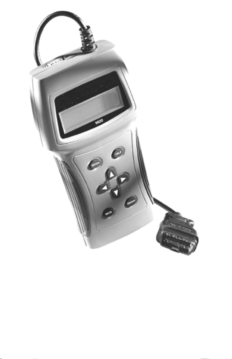
9620 Global
OBD II Scan Tool
Page 2

Table of Contents
Vehicle ServiceInformation ......3
Safety Precautions .....................4
Section 1: Vehicle Computer
Systems------------- 5
1.1 Introduction ..................................... 5
1.1.1 What The Computer Controls . 5
1.1.2 What Has Not Changed .......... 5
1.1.3 Computer Control System ...... 5
1.2 Data Link ConnectorandLocation .6
1.3 OBD II Scan Tool Hookup ................ 6
1.3.1 Keyboard .................................7
1.3.2 Display .....................................7
1.3.3 Lists, Menus, and Questions ...7
1.4 Tool Setup .......................................8
1.4.1 Changing Measurement Units 8
1.4.2 Changing Display Contrast .....8
1.4.3 Displaying Tool Information .... 9
1.4.4 Program Mode .........................9
1.5 Personal Computer (PC) and
PrinterInterface..............................9
1.6 Replacing the Battery ..................... 9
1.7 AC Adapter ......................................9
Section 2: Diagnosing with
theScan Tool ---- 10
2.1 Preliminary Checks ..................... 10
2.2 Connecting the Scan Tool ............ 10
2.3 OBD II Functions List ..................... 11
2.3.1 I/M Readiness ........................11
2.3.2 Read Codes .......................... 12
2.3.3 Pending Codes ..................... 12
2.3.4 Erase Codes ......................... 13
2.3.5 View Data .............................. 13
2.3.6 View Freeze Data ................. 15
2.3.7 O2 Monitor Test ..................... 15
2.3.8 Diagnostic Monitor Tests ...... 16
2.3.9 On-Board Systems ............... 17
2.3.10 Record Data .......................... 17
2.3.11 Vehicle Info ........................... 18
2.3.12 Modules Present ................... 19
2.3.13 Review Data .......................... 19
2.3.14 Print Data .............................. 20
Section 3: Diagnostic Trouble
Codes (DTC) ---- 22
3.1 DTC Format .................................. 22
3.2 Code Lookup ................................ 23
3.3 Diagnostic Trouble Code Ranges 24
Section 4: Help and Trouble-
shooting Tips ---- 25
4.1 How to Use Help ........................... 25
4.2 Scan Tool Problems ..................... 25
4.2.1 Scan Tool does not powerup:25
4.2.2 Scan Tool does not Link
withvehicle:........................... 25
4.2.3 One or more modules drops
the communication link: ...... 26
4.2.4 Keyboard does not function
properly: ................................ 26
4.3 Tool Self-Tests .............................. 26
4.3.1 Display Test ........................... 26
4.3.2 Keyboard Test ....................... 26
4.3.3 Memory Test.......................... 27
4.3.4 Printer Test ............................ 27
4.4 Technical Support ........................ 27
Appendix A: Global OBD II PID
List & Definitions 28
Appendix B: -------- Glossary &
Definitions -------- 31
All information, illustrations and specifications contained in this manual are based on the
latest information available from industry sources at the time of publication. No warranty
(expressed or implied) can be made for its accuracy or completeness, nor is any
responsibility assumed by SPX or anyone connected with it for loss or damages
suffered through reliance on any information contained in this manual or misuse of
accompanying product. SPX reserves the right to make changes at any time to this
manual or accompanying product without obligation to notify any person or organization
of such changes.
2 9620 Professional OBD II Scan Tool
Page 3

Vehicle ServiceInformation
The following is a list of publishers who have manuals containing electronic engine
control diagnostic information. Some manuals may be available at auto part stores
or local public libraries. For others, write for availability and pricing, specifying the
make, model and year of vehicle.
Service Manuals:
Chilton Book Company
Chilton Way
Radnor, PA 19089
Haynes Publications
861 Lawrence Drive
Newbury Park, CA 91320
Cordura Publications
Mitchell Manuals, Inc.
Post Office Box 26260
San Diego, CA 92126
Motors Auto Repair Manual
Hearst Company
250 W 55th Street
New York, NY 10019
Manufacturer Service Manuals:
General Motors:
Buick, Cadillac, Chevrolet, GEO,
GMC, Oldsmobile, & Pontiac
Helm Incorporated
Post Office Box 07130
Detroit, MI 48207
Saturn
Adistra Corporation
c/o Saturn Publications
101 Union St.
Post Office Box 1000
Plymouth, MI 48170
Ford Motor Company:
Ford, Lincoln, & Mercury
Ford Publication Department
Helm Incorporated
Post Office Box 07150
Detroit, MI 48207
Chrysler Corporation:
Chrysler, Plymouth, & Dodge
Chrysler Motors Service Training
26001 Lawrence Avenue
Center Line, MI 48015
Suitable manuals have titles, such as:
Electronic Engine Controls
Fuel Injection and Feedback Carburetors
Fuel Injection and Electronic Engine Controls
Emissions Control Manual
. . . or similar titles
9620 Professional OBD II Scan Tool 3
Page 4

Safety Precautions
General Safety Guidelines to Follow When Working on Vehicles
To prevent accidents that could result in serious injury and/or damage
to vehicle or test equipment, carefully follow these safety rules and
test procedures at all times when working on vehicles:
Always wear approved eye protection.
Always operate the vehicle in a well-ventilated area. Do not inhale exhaust
gases they are very poisonous!
Always keep yourself, tools and test equipment away from all moving or hot
engine parts.
Always make sure the vehicle is in Park (Automatic transmission) or neutral
(manual transmission) and that the parking brake is firmly set. Block the
drive wheels.
Never lay tools on vehicle battery. You may short the terminals together
causing harm to yourself, the tools or the battery.
Never use scan tool if its internal circuitry has been exposed to any liquids.
Never smoke or have open flames near vehicle. Vapors from gasoline and/or
charging battery are highly flammable and explosive.
Never leave vehicle unattended while running tests.
Always keep a fire extinguisher suitable for gasoline/electrical/chemical fires
handy.
Always use extreme caution when working around the ignition coil, distributor
cap, ignition wires, and spark plugs. These components contain high voltage
when the engine is running.
When performing a road test, never operate the scan tool alone while driving
the vehicle. Always have one person drive the vehicle while an assistant
operates the tester.
Always turn ignition key OFF when connecting or disconnecting electrical
components, unless otherwise instructed.
Always follow vehicle manufacturers warnings, cautions and service
procedures.
WARNING!:
Some vehicles are equipped with safety air bags. You must follow
vehicle service manual cautions when working around the air bag
components or wiring. If the cautions are not followed, the air bag may
open up unexpectedly, resulting in personal injury. Note that the air
bag can still open up several minutes after the ignition key is off (or
even if the vehicle battery is disconnected) because of a special
energy reserve module.
4 9620 Professional OBD II Scan Tool
Page 5

Section 1: Vehicle Computer Systems
1.1 Introduction
This section describes the engine computer control system, types of sensors and how
the computer controls engine fuel delivery, idle speed and timing. Additional information
may be found in the technical support books at your local library or auto parts store. The
more known about the computer system, the easier the problem can be diagnosed.
Computer controls were originally installed on vehicles to meet federal government
regulations for lower emission levels and improved fuel economy. This began in the early
1980s when basic mechanical systems were no longer able to accurately control key
engine parameters. A computer could be programmed to control the engine under various
operating conditions, making the engine more reliable. While these early systems were
very limited in scope of their diagnostics, providing only 10-14 trouble codes, they did help
guide the vehicle repair process.
In 1994, manufacturers began equipping vehicles with a new class of computer technology
which puts more processing power under dash than ever before. It is called On-Board
Diagnostics version II, or OBD II. It is required on all vehicles sold in the US beginning
January 1, 1996 (though most domestic manufacturers introduced it earlier than required),
and offers increased system monitoring and diagnostic information. This new system stores
a library of more than 650 general trouble codes and another approximately 400
manufacturer-specific codes, all of which can be accessed with the scan tool. These codes
cover Body Systems (B-Codes), Chassis Systems (C-Codes), Communications Codes
(U-Codes), and Powertrain Systems (P-Codes). Now, basic terms are standardized and
all generic codes will share a common format and terminology that manufacturers and the
Society of Automotive Engineers (SAE) designed.
The OBD II Professional Scan Tool performs OBD II functions on ALL makes of OBD II
compliant vehicles from 1996 and up.
1.1.1 What The Computer Controls
The main control areas of the vehicle computer are fuel delivery, idle speed, spark advance,
and emissions controls. Some on-board computers may also control the transmission,
brakes, and suspension systems as well.
1.1.2 What Has Not Changed
A computer-controlled engine is very similar to the older, non-computerized engine. It is still
an internal combustion engine with pistons, spark plugs, valves, and camshaft(s). The ignition,
charging, starting, and exhaust systems are very similar as well. Test and repair of these
systems are the same as before. The technical manuals for these components provide
instruction on how to perform the tests. Additionally, compression gauges, vacuum pumps,
engine analyzers, and timing lights will continue to be used.
1.1.3 Computer Control System
The vehicle on-board computer, or Powertrain Control Module (PCM), is the heart of the
system. It is sealed in a metal box and connected to the rest of the engine by a wiring
harness. The PCM is commonly located in the passenger compartment, behind the
dashboard (kick panel position), although some manufacturers locate the PCM in the
engine compartment. The PCM is programmed by the factory. The program is a complex
list of lookup tables and instructions telling the computer how to control the engine based
on various driving conditions. It does this using sensors to monitor what is happening and
then provide feedback through a network of switches and actuators throughout the vehicle.
9620 Professional OBD II Scan Tool 5
Page 6
1.2 Data Link ConnectorandLocation
Welcome To
The Global OBDII
SCANTOOL
Press HELP For Key |
Button Information
Press ENTER To Cont
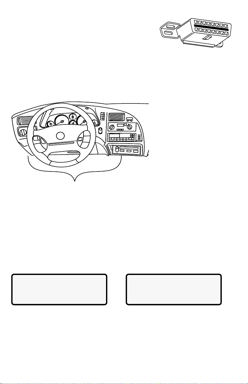
The scan tool communicates with the vehicle PCM via a
data link connector (DLC) also referred to as a J1962
connector. The term J1962 is taken from physical and
electrical specification number assigned by SAE (Society of
Automotive Engineers). A standardized DLC means all compliant
vehicles will use the same DLC with the generic link information available on the same
pins regardless of vehicle make or model. In addition to the connector definitions, is a
guideline on where the connector is to be located in the vehicle. This guideline states
that the DLC should be located under the dashboard on the driver side of the vehicle.
However, not all OBD II DLCs are located under the dash on the driver side. If required,
refer to vehicle service documentation for the DLC location.
DLC Location
1.3 OBD II Scan Tool Hookup
The OBD II cable attached to the scan tool fits the OBD II DLC. Because the OBD II J1962
connector contains dedicated pins for power and ground, only a single cable connection is
required for both scan tool power and PCM communication.
Connect the scan tool to the DLC. This connection will provide power for the scan tool.
The DLC maintains power even when the ignition is turned off. Therefore, connection to
the battery is not required.
When the scan tool powers up, a series of screens are displayed. The screens start with
a Welcome screen and end with a Key Button Help screen.
The screens between the Welcome screen and the Key Button Help screen are for
tool self-tests and software ID. Refer to this software ID when contacting the Actron
technical support line with a problem. To review the key button definitions, push the
(HELP) key; otherwise, press ENTER to continue.
The scan tool requires a minimum of 8 volts to power up. If a problem occurs with powerup, review Section 4: Help and Troubleshooting Tips.
6 9620 Professional OBD II Scan Tool
Page 7

1.3.1 Keyboard
OBDII Function List |
3)Erase Codes ]
4)View Data [
`5)View Freeze Data
The scan tool software was designed for ease of use in navigating through operational
menus. Simply follow instructions that match keyboard symbols.
Keyboard Functions
The scan tool uses 8 keys to navigate through the software-user interface:
ENTER Used to select or answer a software request.
HELP Used to request help when the (|) symbol is displayed in the lower right
hand corner of the display.
BACK Used to move one screen back in scan tool flow.
ARROWS
UP/DOWN Used to move the solid cursor (`) in the direction of the arrow or
scroll the data list in the direction you want to move the list.
LEFT/RIGHT Used to select and deselect items in custom lists. This key is
also used to answer questions by selecting yes or no.
ON/OFF Used to turn scan tool ON and OFF when not powered by vehicle.
Momentarily press and release button when turning ON to allow boot process.
1.3.2 Display
The scan tool has a 4 line x 20 character backlit
Liquid Crystal Display (LCD) for easy viewing. The
backlighting is disabled when the scan tool is
powered by its internal batteries. This gives the
user a large viewing area to display most Help
and Instructional messages. It puts more
information on the display instead of having to refer to printed materials. Again the display will
support a number of helpful characters that will prompt the user through test routines. These
characters are shown below:
| Question Mark in lower right corner means there is help available for this screen or
current selectable item.
` Pointer (cursor) is used to indicate current selectable choice.
[ Down Arrow indicates there is additional information on the next screen.
] Up Arrow indicates there is additional information on previous screen.
« Diamond to the left of item indicates it is selected.
The screen at the right shows how some of these symbols will look on your display.
1.3.3 Lists, Menus, and Questions
The scan tool is designed to be as intuitive as possible. Its functions and controls are easy to
understand and use. All menu and screen lists operate the same way. Use the UP/DOWN
arrow keys to move the cursor to a selection. The ENTER key selects that function or item. The
screen examples below show a few selections available on the OBDII Function List.
For example: to read vehicles DTCs, move cursor to Read Codes and press ENTER.
To make a different choice, use the DOWN arrow key to move the cursor down to View Data
and press ENTER. This will select the View Data function.
Sometimes, a list will be longer than three or four items, and will not fit on a single screen. In
this case, the DOWN arrow symbol ([) is visible in the last column of the display, indicating
that there are more choices on the next screen, as shown below on the left. Use the DOWN
arrow key to move the cursor down the list.
9620 Professional OBD II Scan Tool 7
Page 8

At the bottom of the list, there is now only an UP arrow symbol (]) visible in the last
View Instructions
For Creating Custom
Data List?
Yes <No>
OBDII Function List |
`1) I/M Readiness
2)Read Codes [
3)Pending Codes
OBDII Function List |
4)View Data ]
5)View Freeze Data [
`6)Record Data
Setup Tool For
1) English/Metric
`2)Display Contrast
3)Tool Information
]Increase Contrast
[Decrease Contrast
Press ENTER To Save
Setup Tool For
`1) English/Metric
2)Display Contrast [
3)Tool Information
Measurement Units
`English(Default)
Metric
column indicating the last function in the list has been reached. To return to previous
screens, press the UP arrow key. The UP/DOWN arrow keys work the same way when
scrolling through text such as the Help screen.
The Scan Tool may ask a question which requires a response from user. These will
always be YES or NO questions, and are answered with cursor and Arrow keys.
In these screens, brackets <> will automatically appear next to default response. To
accept default choice, simply press ENTER. Use LEFT/RIGHT arrow key to move brackets
to other response and press ENTER.
1.4 Tool Setup
Only functions of the Main Menu that pertain to getting started with scan tool are discussed
in the following paragraphs. For all other menu selections available, refer to Section 4:
Help and Troubleshooting Tips.
Tool Setup is used to change the scan tool default
unit settings. To change the scan tool settings,
select Tool Setup from the MAIN MENU and
press the ENTER key.
NOTE: Settings chosen will remain until 9 volt battery is dead.
1.4.1 Changing Measurement Units
After selecting Tool Setup option, tool setup menu appears. To choose English or Metric
measurement units, use UP/DOWN arrows to make selection and press ENTER. The
display will look like the following screen:
1.4.2 Changing Display Contrast
From the Tool Setup menu, select Display Contrast and press ENTER. Use the UP/
DOWN arrow keys as indicated on the screen:
8 9620 Professional OBD II Scan Tool
Page 9

1.4.3 Displaying Tool Information
Setup Tool For
1) English/Metric
2)Display Contrast
`3)Tool Information
Tool Information:
`Serial No: 1360447]
SW ID: 86E3H[
HW Ver: 1
From Tool Setup menu, select Tool Information and press ENTER. Use UP/DOWN
arrow keys to view information. Record information in case the need to contact customer
service arises.
1.4.4 Program Mode
Used to update scan tools software. Instructions will be provided with updates.
1.5 Personal Computer (PC) and PrinterInterface
Scan tool is equipped with a standard 9 pin serial interface. Use connection to attach
tool to a PC or compatible printer.
Personal Computer
Use serial adapter to connect to a PC when updating to current available software.
Software updates may be purchased from Actron by calling the toll free number
provided.
Refer to Section 2.4.13 Print Data for default serial port settings and to make
changes to settings.
Printer Connection
Connect a compatible printer cable to the scan tool and Printer using specifications
below:
- If the printer connector is a 25 pin connector or if the gender is not compatible, an
adapter will be required.
- Adapters are available at most local PC stores or electronics outlets.
- A NULL modem adapter is required to be connected in series with scan tool and
printer cable.
1.6 Replacing the Battery
To replace the 9V battery, do the following:
Remove screw from back of scan tool case.
Slide battery cover back to disengage hooks.
Replace 9V battery and place in compartment.
Slide battery cover up, making sure hooks engage scan tool case.
Install screw.
1.7 AC Adapter
The AC power adapter powers the tool when you review codes and print off-vehicle and when
you update the software vial a personal computer. The Scan tool is equipped to accept any
110 Vac12 Vdc AC adapter with the following specifications.
300 mA minimum unregulated wall power adapter.
Dimensions - 5.5 mm Outside Diameter, 2.5 mm Inside Diameter.
9620 Professional OBD II Scan Tool 9
NEG
POS
Page 10
Section 2: Diagnosing with theScan Tool
FRONT
OF CAR
HVAC
CRUISE
BRAKE BOOSTER
TO TRANS
MODE
EGR
VAC
REG
FUEL
PRESS
REG
EGR
VAC
REG
9RAC2LAB
T
ER
P
A.
M
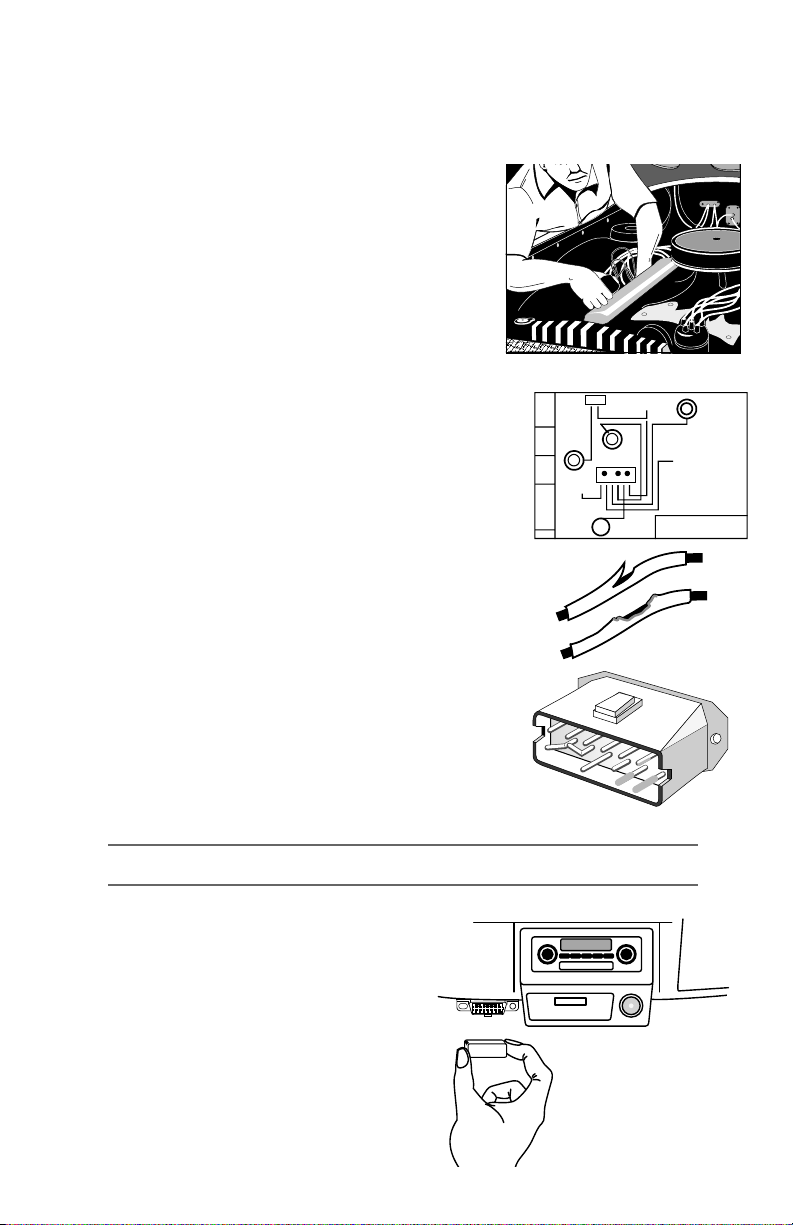
2.1 Preliminary Checks
Before using scan tool, perform a complete visual inspection. Many driveability problems
are found by visual inspection, saving time. Check the following items before proceeding
with scan tool testing:
1. Has vehicle been serviced recently? Sometimes
things get connected in the wrong place, or not at all.
2. Dont take shortcuts. Inspect hoses and wiring which
may be difficult to see because of location beneath air
cleaner housings, alternators and similar
components.
3. Inspect air cleaner and ductwork for defects.
4. Check sensors and actuators for damage.
5. Inspect all vacuum hoses for:
Correct routing. Refer to vehicle service manual, or
Vehicle Emission Control Information (VECI) decal
located in engine compartment.
Pinches and kinks.
Splits, cuts or breaks.
6. Inspect wiring for:
Contact with sharp edges (this happens frequently).
Contact with hot surfaces, such as exhaust manifolds.
Pinched, burned or chafed insulation.
Proper routing and connections.
7. Check electrical connectors for:
Corrosion on pins.
Bent or damaged pins.
Contacts not properly seated in housing.
Bad wire crimps to terminals.
Connector problems are common in engine control
system. Inspect for corrosion, bent, pushed out, or over
expanded pins.
Note: Some connectors use special grease on contacts to prevent corrosion. Do not wipe
off! Obtain grease, from vehicle dealer. It is a special type for this purpose.
2.2 Connecting the Scan Tool
Remove protective cap from data link connector,
if present. Connect scan tool and follow scan
tool prompts. Use scan tool 9V battery to do selftests, review codes, code lookup or print data
when connection to vehicle is not required.
When scan tool powers up, a series of screens
are displayed. The screen starts with Welcome
and ends with a Key Button Help.
10 9620 Professional OBD II Scan Tool
Diagnostic
Connector
Page 11

After pressing ENTER from HELP Screen, the
MAIN MENU |
`1) Vehicle Diagnosis
2)Tool Setup [
3)Tool Self Test
OBDII Function List |
`1) I/M Readiness
2)Read Codes [
3)Pending Codes
Erase Data From
Previous Vehicle
Test?
YES <NO>
Turn Key Off
For 10 Seconds
Then Turn Key On
Then Press ENTER
OBDII Function List |
`1) I/M Readiness
2)Read Codes [
3)Pending Codes
Main Menu displays. Select Vehicle Diagnosis
and press ENTER.
The scan tool asks to erase data from previous
test. Use LEFT/RIGHT arrow keys to select a
response and press ENTER.
A message displays Turn Key Off For 10
Seconds, Then Turn Key On and Then Press
ENTER.
2.3 OBD II Functions List
Use UP/DOWN arrow keys to move cursor(`). Once selection is made, press ENTER.
Press and release BACK key to return to OBD II Function List. Pressing BACK key from
the OBD II Function List returns scan tool to Main
Menu. The first time scan tool communicates with
vehicle, the communication type is automatically
detected, and is used until scan tool is turned
OFF or another vehicle is diagnosed.
Not every vehicle will have every function
listed. If function or part of a function selected is not supported by a vehicle, a
message screen informing of this will be shown.
NOTE: If an Operating Error message is displayed, make sure the OBD II J1962 cable is
securely attached, and ignition key is ON. Cycle ignition key to OFF for 10 seconds,
then ON. This may be required to reset the PCM. If required, select Yes to test again.
If problem still exists, refer to Section 4: Help and Troubleshooting Tips.
2.3.1 I/M Readiness
Purpose of the I/M Readiness test is to display current information on emissions-related
systems. These systems are required by OBD II regulation to be monitored for emissions
testing. OBD II I/M Readiness Monitors are strategies designed to test operations of
emission related systems or components. The computer module uses these monitors
to check for correct operations of system and components as well as out of range values.
The computer module may perform a special test on a system or component to complete
the monitor. It may be required to operate vehicle under certain conditions in order to
perform an accurate test. If computer module loses power, or codes are erased, monitors
may be cleared. The scan tool displays the state of vehicle OBD II Monitors.
To enter I/M Readiness viewing mode, select I/M Readiness from OBD II Function List
and press ENTER.
A list of On-Board system readiness tests and
their status will be displayed. Use vehicle service
manuals for more information on emissionrelated monitors and their status.
Below are examples of completed versus not
completed I/M Readiness screens:
Use the UP/DOWN arrow keys to view monitor list. The monitor list consists of the OBD
II monitor name followed by monitor state. A monitor that is not supported by test vehicle
9620 Professional OBD II Scan Tool 11
Page 12

Code P0443
EVAP Emission
Control System [
Purge Valve C Fault
OBDII Function List |
1) I/M Readiness
2)Read Codes [
`3)Pending Codes
will be followed by n/a. A monitor that has been completed is followed by ok. If not
SINCE DTCS CLEARED
Misfire Monitor ok |
Fuel System Mon inc
Catalyst Mon n/a
OBDII Function List |
1) I/M Readiness
`2)Read Codes [
3)Pending Codes
On-Board Readiness
Tests Are Complete.
Use [ To View Test
Not All Supported
On-Board Readiness
Tests Are Complete.
Use [ To View Test
DTCs Found: 2
Use [ To View DTCs
Write Down Codes
For Reference.
System Pass:
No DTCs Found.
Press BACK For
OBDII Function List
This Driving Cycle
Misfire Monitor n/a
Fuel System Mon ok[
Catalyst Mon inc
completed, inc will be displayed. Use the UP/
DOWN arrow keys to scroll through the list.
NOTE: In addition to displaying the state of the
Press the ENTER key to return to the OBD II
Function List.
monitor since the last time DTCs were
cleared, some vehicles will display the
state of the monitors for this drive cycle.
Use the LEFT/RIGHT arrows to switch
between these screens
2.3.2 Read Codes
The Read Codes function retrieves Diagnostic Trouble Codes (DTCs) from vehicles
computer modules. This function can be performed with the key on and the engine off or
the key on and engine running.
These codes cause the computer to illuminate
the Malfunction Indicator Lamp (MIL) when an
emission-related or driveability fault occurs. The
MIL is also known as the service engine soon
or check engine lamp.
Select Read Codes and press ENTER. The scan tool retrieves the DTCs stored in the
vehicles computer module(s).
The scan tool displays the DTCs or a message
stating SYSTEM PASS: NO CODES FOUND.
Press the DOWN arrow key to view the DTCs or
press the BACK key to return to the OBDII
Function List.
Write down the DTCs for reference, then press BACK to return to the OBDII Function List.
2.3.3 Pending Codes
Pending Codes are also referred as continuous monitor and maturing codes. An
intermittent fault causes computer to store a code in memory. If fault does not occur
again within 40 warm-up cycles, the code clears
from memory. If the fault occurs a specific number
of times, the code matures into a DTC. This
function can be performed with the key on and
engine running or not.
12 9620 Professional OBD II Scan Tool
Page 13

Select Pending Codes and press ENTER key.
P0389 Mod$1E 1 of 2
Crankshaft Position
Sensor B [
CKT Intermittent
Command Sent
Press ENTER To Cont.
OBDII Function List |
`4)Erase Codes ]
5)View Data [
6)View Freeze Data
Erase Diagnostic
Results and Codes?
Are You Sure?
YES <NO>
OBDII Function List |
4)Erase Codes ]
`5)View Data [
6)View Freeze Data
Codes Found: 2
Use [ To View Codes
Write Down Codes
For Reference..
System Pass:
No Faults Detected.
Press BACK Key For
Function List
The scan tool displays codes or a message stating SYSTEM PASS NO FAULT
DETECTED. Press DOWN arrow key to view DTCs or press BACK key to return to OBDII
Function List.
The codes display in same format as Read
Codes. The DTC number and computer module
that stored it display on first line. Use UP/Down
arrow keys to view codes.
Press BACK to return to OBDII Function List.
2.3.4 Erase Codes
The Erase Codes function deletes DTCs from vehicles computer memory. Perform this
function only after systems have been checked completely and DTCs have been
documented. This function should be performed with the key on and the engine off.
After servicing vehicle, delete stored DTCs and verify no codes have been reset. If DTCs
return, the problem has not been corrected or other faults are present.
In addition to clearing DTCs, the Erase Codes function may also erase Freeze Frame,
O2 Sensor Data, System Monitors, and On-Board Monitor test results.
Select Erase Codes and press the ENTER key. A message appears asking if you are
sure. Press LEFT ARROW to move brackets to desired response and press ENTER.
Selecting NO displays a COMMAND CANCELLED message prompting to press ENTER
to return back to OBDII Function List. Selecting YES displays a screen prompting to turn
ignition key to on and engine off and press ENTER key.
The scan tool sends erase command. Press
ENTER to continue and return to OBDII Function
List.
2.3.5 View Data
The View Data function allows viewing of vehicles Parameter Identification data (PID) in
real time. As the computer monitors the vehicle, the information is simultaneously
transmitted to scan tool. Apart from Read Codes, View Data is most useful diagnostic
function for isolating cause of a vehicle
operation problem. Viewing data is also used
for observing sensor data and status of
switches, solenoids, and relays.
Select View Data from OBDII Function List and
press ENTER. The scan tool displays a menu
with display options.
Use the UP/DOWN arrow keys to select an option and press ENTER.
9620 Professional OBD II Scan Tool 13
Page 14

Select Custom List
«ABSLT TPS(%) ]
`«CALC LOAD(%) [
COOLANT(oF)
View Instructions
For Creating Custom
Data List?
YES <NO>
ABSLT TPS(%) 0.0
CALC LOAD(%) 5.3
ENGINE(RPM)($10) 180[
ENGINE(RPM)($1A) 865
Select Display Line
2 Lines ]
3 Lines
`4 Lines(Default)
Entire Data List
Select Data To View
Entire Data List
`Custom Data List
View Data Setup
Select Entire Data List to display all PIDs supported by vehicle under test.
Custom Data List
To display only certain PIDs, select Custom Data
List. The ability to display certain PIDs helps in
diagnosing a specific driveability symptom or
system.
If choosing to view a Custom Data List, the scan
tool asks if help is needed to view the
instructions. Select desired response and press
ENTER.
Use UP/DOWN arrow keys to move
cursor up and down through list.
Use RIGHT arrow key to select or deselect
PIDs. Selected PIDs are marked with «
symbol.
Use LEFT arrow key to deselect all
marked PIDs.
Use the ENTER key to link to the vehicle and retrieve the marked PIDs.
When finished selecting PIDs, press ENTER key to begin viewing them.
NOTE: Refer to Appendix A for a complete list of PIDs.
View Data Setup
View Data Setup allows display of PIDs on one,
two, three or four lines. Selecting fewer lines of
data provides faster update speeds. The scan
tool default is four-line display.
When scan tool links to vehicle, PIDs will display. Navigate through PID list with following
keys:
Press UP/DOWN arrow keys to scroll Up/
Down line-by-line through list.
Press LEFT/RIGHT arrow keys to Page
Up/Page Down.
Press BACK key to return to Select Data
To View menu.
The same parameter may appear twice if vehicle is equipped with more than one computer
module Powertrain Control Module (PCM), Transmission Control Module (TCM), etc. The
scan tool identifies them by identification names (ID) assigned by manufacturer (i.e. $10,
$1A, etc). The computer module ID blinks in parentheses. If one or more modules stops
responding, the scan tool displays a message that the module is not responding and asks to
continue without it. If NO is selected, scan tool attempts to reestablish communication with
that module.
14 9620 Professional OBD II Scan Tool
Page 15

2.3.6 View Freeze Data
FREEZE FRAME DATA
TROUB CODE P0443
CALC LOAD(%) 85.6[
ENGINE(RPM)($10) 1120
OBDII Function List |
4)Erase Codes ]
5)View Data [
` 6)View Freeze Data
FRAME 1 Mod $1A
TROUB CODE P0443
CALC LOAD(%) 85.6[
ENGINE(RPM)($10) 1120
When an emission-related fault occurs, certain vehicle conditions are recorded by the
on-board computer. This information is referred to as a Freeze Frame data. The information
is a snapshot of operating conditions at time of a fault. This data can be overwritten by
faults with a higher priority.
NOTE: If codes were erased, then freeze frame data may not be stored in vehicle memory.
Select View Freeze Data from the OBDII Function
List and press ENTER.
The scan tool links to the vehicle and displays
Freeze Frame data. Use UP/DOWN arrow keys
to scroll through data.
NOTE: If more than one computer module responds
with freeze frame data, then the frame
number and module display on the first line.
Press the LEFT/Right key to change modules.
When done, press BACK key to return to OBDII Function List.
2.3.7 O2 Monitor Test
NOTE: The O2 Monitor Test is NOT AN ON-DEMAND TEST. O2 sensors are NOT tested
when selected via the menu. The O2 sensors are tested when engine operating
conditions are within specified limits.
NOTE: If vehicle communicates using a Controller Area Network (CAN), O2 Monitor Tests
are NOT supported by vehicle. A message is displayed. See Diagnostic Monitor
Test to see O2 Monitor Data.
OBD II regulations require that applicable vehicles monitor and test the oxygen (O2)
sensors to determine problems related to fuel and emissions. The O2 Monitor Test
allows retrieval of completed O2 sensors monitor test results.
O2 sensors are located before (upstream) and after (downstream) catalyst(s). The
sensors are named (xy) for their position relative to both cylinder banks and catalysts.
The O2 sensor for cylinder bank 1 has the prefix 1y while the O2 sensor for
cylinder bank 2 has the prefix 2y.
The O2 sensor upstream of the catalyst (closest to the engine) has the suffix x1
while the O2 sensor downstream of the catalyst has suffix x2. If vehicle contains
more catalysts, the O2 sensor downstream of the second catalyst has the suffix
x3 and the O2 sensor downstream of the next catalyst has the suffix x4.
For example, O2S 21 is the upstream O2 sensor for cylinder bank 2.
9620 Professional OBD II Scan Tool 15
Page 16

The following O2 sensor tests are available:
Low Volts for Switch
O2S 1-1(V) 1.15
O2S 1-2(V) ---[
O2S 2-1(V) 1.28
OBDII Function List |
`7)O2 Monitor Test ]
8)Non-Contin Test [
9)On-Board Systems
O2 Sensor Tests
`1) RICH-LN Thresh
2)LN-RICH Thresh [
3)Lo V For Switch
OBDII Function List |
7)O2 Monitor Test ]
`8)Diag Mon Test [
9)On-Board Systems
Diag Mon Data Avail
` O2 Sensor B1S1
Catalyst B1 [
EVAP (0.090)
Non-Cont Tests Avail
`$0 1
$03 [
$05
Rich to Lean sensor threshold voltage
Lean to Rich sensor threshold voltage
Low sensor voltage for switch time
High sensor voltage for switch time
Rich to Lean sensor switch time
Lean to Rich sensor switch time
Minimum sensor voltage test cycle
Maximum sensor voltage test cycle
Time between sensor transitions
Select O2 Monitor Test from OBDII Function List and press ENTER.
Select desired test from menu and press ENTER. Grouping O2 sensor tests together
makes data easier to compare.
The O2 sensors located upstream (before catalyst) may perform differently than the ones
located downstream (after the catalyst).
Oxygen sensor tests not supported by the vehicle display three dashes as the value.
Press the BACK key to return to the O2 Sensor Tests menu or press ENTER to return to
the OBDII Function List.
2.3.8 Diagnostic Monitor Tests
The Diagnostic Monitor Test function is different for Non-CAN and CAN vehicles.
Non-CAN vehicles Diagnostic Monitor Tests receives test results for emission-related
powertrain components and systems
CAN vehicles Diagnostic Monitor Tests receives test results for emission-related
powertrain components and systems that
The Diagnostic Monitor Test function is useful after servicing or after erasing the vehicles
memory. Test results do not necessarily indicate a faulty component or system.
Vehicle manufacturer is responsible for assigning test and component IDs
Select Diagnostic Monitor Test from the OBDII
Function List and press ENTER. A list of tests
applicable to the vehicle are displayed. Select a
test and press ENTER.
NON-CAN VEHICLE
16 9620 Professional OBD II Scan Tool
not continuously monitored.
are or are not continuously monitored.
CAN VEHICLE
Page 17

Applicable tests are displayed . Select a test and press ENTER.
OBDII Function List |
7)O2 Monitor Test ]
8)Non-Contin Test [
`9)On-Board Systems
OBDII Function List |
`10)Record Data ]
11) Vehicle Info [
12)Modules Present
Diag Mon Data Avail
$01
$05 [
$10 ~
Diag Mon Data Avail
O2 Sensor B1S1
Catalyst B1 [
EVAP (0.090) ~
Requested test results are displayed on Scan Tool
NON-CAN VEHICLES
On Non-CAN vehicles Scan Tool displays:
On the 1st line is where the test data (test ID) came from.
On the 2nd line is the test heading.
On the 3rd and 4th line is the test measurement (MEAS), specification value (SPEC) and
status (STS). Measurements and Specification values are hexadecimal numbers (i.e.,
$1A, $FE, $11.)
On CAN vehicles Scan Tool displays:
On the 1st line is where the monitor test data came from. ($00) represents the
source module id from where the data originated.
On the 2nd line is the test performed. The test performed can be $## if test is not
defined. Refer to vehicle service manual for details.
On the 3rd line are the measured value and units in (Volts, Amps, Seconds, etc.) and
status of monitor test data.
On the 4th line, the minimum and maximum limits are shown for the monitor test data.
If additional tests are present, use the up and down arrow to view test results.
Refer to appropriate vehicle service manual for test IDs and definitions.
Press BACK key to return to the Diag Mon Test menu or press ENTER key to return
to OBDII Function List.
CAN VEHICLES
2.3.9 On-Board Systems
This test allows scan tool to control operation of vehicle components, tests or systems.
Some manufacturers do not allow tools to control vehicle systems. A vehicle not supporting
an on-board system is identified by a message displayed when selected.
NOTE: Refer to vehicle service manual for on-board systems instructions.
Select On-Board Systems from OBDII Function
List and press ENTER. A list of on-board systems
and components available for testing display on
screen.
Select a test and press ENTER to activate test.
The manufacturer is responsible for determining criteria to automatically stop test. Refer
to appropriate vehicle service manual.
2.3.10 Record Data
Record Data function records PIDs while vehicle is parked or being driven. This function
is mainly used for diagnosing intermittent driveability problems that cannot be isolated
by any other method. The scan tool can maintain only one recording at a time. Be sure to
thoroughly review old recording before erasing.
Select Record Data from OBDII Function List
and press ENTER. Follow all instructions on
display.
9620 Professional OBD II Scan Tool 17
Page 18

OBDII Function List |
10)Record Data ]
`11)Vehicle Info [
12)Modules Present
If a recording currently exists in memory, a
Playback Data?
<Yes> No
Cannot Record. Old
Recording Filled Up
Memory. Erase Old?
<YES> NO
Pick Trigger Method
`1) Manual Trigger
2)Trigger On Codes
message prompting to erase data is displayed.
Note: Make sure to review old recorded data
Scan tool retrieves a list of supported PIDs. After list is generated, scan tool prompts to
select type of data to view. Refer to View Data described earlier in this section to setup
Entire or Custom Data Lists.
On next screen, select a method to trigger a
recording. Manual Trigger allows technician to
use ENTER key. Trigger On Codes automati-
cally triggers when a DTC is indicated by vehicle.
Once trigger method is selected, scan tool will begin recording data when trigger event
occurs either a DTC occurs or ENTER key is pressed. The time is recorded and data
from the last five frames is saved. Data will continue to be saved until either the record
memory is full or the technician presses ENTER.
Press ENTER and the scan tool establishes a communication link with the vehicle.
If Manual Trigger is selected, scan tool initializes by recording first five frames. When
done, press ENTER. If Trigger On Codes was selected, then scan tool triggers when a
DTC is stored in vehicle. Press BACK key twice to return to OBDII Function List.
before erasing
WARNING!
TWO PEOPLE SHOULD BE IN VEHICLE WHEN DRIVING ON ROAD,
ONE TO DRIVE AND THE OTHER TO ATTEND TO THE EQUIPMENT.
Scan tool recording times vary. A recording consists of 5 frames of data prior to trigger
and several frames after trigger. Amount of PIDs recorded determine number of frames.
After a recording, scan tool displays a prompt to
playback recording. Answer YES to display
recorded data or NO to return to OBDII Function
List.
2.3.11 Vehicle Info
Vehicle Info function enables scan tool to request vehicles VIN number and calibration
ID(s) which uniquely identifies software version in vehicle control module(s).
This function applies to Model Year 2000 and later OBD II compliant vehicles. The scan
tool cannot verify if data returned is correct for scanned vehicle. This information is
provided by vehicle manufacturer. The Vehicle Info test must be completed with the key in
the ON position and the Engine OFF.
Calibration Verification Numbers (CVNs) are calculated values required by OBD II
regulations with the vehicle engine off. CVNs are reported to determine if emissionrelated calibrations have been altered. Multiple CVNs may be reported for a control
module. The calculation may take several minutes first time the CVNs are requested.
Select Vehicle Info from OBDII Function List and
press ENTER.
If the message INVALID displays on screen, then
data returned is incorrect, or not formatted in
accordance with OBD II specification.
18 9620 Professional OBD II Scan Tool
Page 19

Scan tool displays VIN, Calibration ID, and CVNs
OBDII Function List |
10)Record Data ]
11) Vehicle Info [
`12)Modules Present
OBDII Function List |
`13)Review Data ]
14)Print Data
15)Code Lookup
Review Data
5)O2 Monitor ]
6)Non-Continuous [
`7)Playback
No Link Established
Controller List
Not Available
ID Protocols
$10 ISO*
$18 ISO* [
$1A ISO*
No Recording Is
Present. Please
Make Recording
First.
MIL STATUS ON
CALC LOAD(%) 5.3
ENGINE(RPM)($10) 180[
FRAME: 1 TM: 4.4
VIN # 1 MOD $10
1F1FS11P0S2100001
[
if supported by vehicle. In example screens, MOD
$10 returned data. Use UP/DOWN arrow keys to
scroll . CVNs are shown as a hexadecimal
number.
Press BACK or ENTER to return to OBDII Function List.
2.3.12 Modules Present
OBD II information may be provided by a single
module or many separate modules. The scan
tool identifies module IDs and communication
type for OBD II modules in vehicle.
Select Modules Present from OBDII Function
List and press ENTER.
When selecting this function, scan tool checks for an established communication link. If
no link is made, a message displays stating so. If link was successful, module(s) and
communication type(s) display on screen.
2.3.13 Review Data
Review Data function allows review of information stored in scan tools memory. The
scan tool does not require power from vehicle to perform this function. Internal battery
power can be used.
Select Review Data from OBDII Function List and press ENTER. Only one function,
Playback, needs detailed instructions.
Playback
Playback function is used to play back a recording. This function is very similar to View
Data. The only difference is View Data is real time viewing of PIDs, while Playback is a
viewing of previously recorded PIDs.
To play back recorded PIDs, select Playback and press ENTER key.
9620 Professional OBD II Scan Tool 19
Page 20

Select Baud Rate
`9600(Default)
1200 [
2400
Select Data Bits
`8 (Default)
Select Stop Bits
1 Bit(Default)
`2 Bits
The scan tool informs if a recording does not exist. Otherwise, scan tool plays back
OBDII Function List |
13)Review Data ]
`14)Print Data
15)Code Lookup
Tool Set To Default |
Printer Settings.
Change Settings?
YES <NO>
Entire Data List or Custom Data List, depending on how data was recorded.
The screen is composed of three lines of data and one line for the frame number and
timestamp (in seconds). Negative frames and timestamps indicate data recorded before
the trigger event. Positive frames and timestamps indicate data recorded after the trigger
event.
Use UP/DOWN arrow keys to scroll through the recorded PID data of each frame.
The end of the list is reached when only the (up) icon is visible.
Use the LEFT/RIGHT arrow keys to scroll back and forth through the frames. The
LEFT key advances to the next frame, wrapping around to earliest frame when
the final frame is reached. The RIGHT arrow key goes back to the previous frame,
again wrapping around to the final frame.
Different vehicles communicate at different speeds and support a different number of
PIDs. Therefore, the maximum number of frames that can be recorded will vary.
Some vehicles wait a long period of time to store a trouble code after the driveability
problem occurs. If you selected Trigger On Codes when you made your recording, you
might not see any drastic change in data parameters before and after the trigger point. In
cases like this, the user can manually trigger the recording when the symptom is observed.
When done, press BACK to return to Review Data or to the OBDII Function List.
2.3.14 Print Data
This function allows you to print the diagnostic information stored in the scan tool. The
scan tools internal battery power can be used to print data.
Select Print Data and press the ENTER key. The scan tool informs you of the printer
settings (Custom or Default), then asks if you wish to change them. If settings are not
changed, then skip the next section and continue with on the next page.
Changing the Printer Settings
NOTE: The default values are designated on the display with the word (Default) next to
After selecting YES and pressing ENTER, the
first item to change is the Baud Rate. Use the
UP/DOWN arrow keys to select an option and
press the ENTER key.
Press ENTER when the Select Data Bits screen
displays. There is nothing to select.
In the Select Stop Bits screen, select 1 BIT or
2BITS and press ENTER.
the option. Refer to the printer manual for the settings.
20 9620 Professional OBD II Scan Tool
Page 21

Next, select the parity and press ENTER.
Select Parity
`None (Default)
Odd
Even
Printer
`Fast (Default)
Slow
The ASCII Character
Set Will Be Printed
Once
Press ENTER To Cont.
Select Print Data
1)I/M Readiness
`2)DTC (Codes) [
3)Pending Codes
Make Sure Printer
Is Turned On, Online
& Connected To Tool.
Press ENTER To Cont.
Is Printout OK?
<YES> NO
Select Print Data
5)O2 Monitor ]
6)Non-Continuous [
`7)Playback
Finally, select the printer speed, FAST or SLOW,
and press ENTER.
Now that the printer settings are changed, it is
time to verify the settings. Press the ENTER key
to print the ASCII character set.
Follow the instructions displayed on the screens.
If the printout is OK, press ENTER. Refer to the
settings in the printer manual if the printout is
not OK.
Printing Data (except Playback)
Next, select the data to be printed and press
ENTER. The scan tool displays the menu of
those functions that store data and can be
printed.
Make sure the printer is turned on, on-line and
connected.
When the selected data does not exist in the scan tools memory, a message informs
you to run the function. If the selected data is stored in the scan tool, the data automatically
transmits to the printer.
Press ENTER to return to the Select Print Data screen. Either select another item to print
or press BACK to return to the OBDII Function List.
Printing Playback Data
When printing playback data, the Start Frame and
End Frame need to be defined.
After selecting Playback and pressing ENTER,
the Start Frame screen shows the earliest possible frame. Use the ([) or (]) to change the frame
number and then press ENTER.
Next, the End Frame screen displays the latest possible frame. Use the Scroll Wheel to
change the frame number and then press ENTER.
The scan tool starts transmitting to the printer, frame-by-frame. After all the frames have
been sent, press ENTER to return to the Select Print Data screen. Press the BACK key to
return to the OBDII Function List.
9620 Professional OBD II Scan Tool 21
Page 22

Section 3: Diagnostic Trouble Codes (DTC)
3.1 DTC Format
Diagnostic Trouble Codes (DTCs) consist of a five-digit alphanumeric code. The DTC
format and types are shown below. When the on-board computer recognizes and identifies
a problem, a DTC for that fault is stored in memory. These codes are intended to help you
determine the root cause of a problem.
P 0 1 0 1
Bx - Body
Cx - Chassis
Px - Powertrain
Ux - Network Comm.
x = 0, 1, 2 or 3
Example:
P0101 - Mass or Volume Air Flow
Circuit Range/Performance Problem
Vehicle Specific System
Specific Fault Designation
Powertrain Codes
P0xxx - Generic (SAE)
P1xxx - Manufacturer Specific
P2xxx - Generic (SAE)
P30xx-P33xx - Manufacturer Specific
P34xx-P39xx - Generic (SAE)
Chassis Codes
C0xxx - Generic (SAE)
C1xxx - Manufacturer Specific
C2xxx - Manufacturer Specific
C3xxx - Generic (SAE)
J2012 and ISO 15031-6 are standards for all DTCs, established by SAE, International
Organization for Standardization (ISO) and other governing bodies. Codes and definitions
assigned by this specification are known as Generic OBD II codes. OBD II requires
compliance with standards, and has made it standard for all cars, light trucks, APVs,
MPVs, and SUVs sold in U.S. Codes not reserved by SAE are reserved for manufacturer
and referred to as Manufacturer Specific.
Periodically, new DTCs are defined and approved by SAE, ISO and other governing
bodies. The scan tool software will be periodically updated to reflect these changes. For
more information regarding DTC updates, please call our Technical Support line at
1-800-228-7667 (8:00 6:00 EST Monday Friday).
Body Codes
B0xxx - Generic (SAE)
B1xxx - Manufacturer Specific
B2xxx - Manufacturer Specific
B3xxx - Generic (SAE)
Network Communication Codes
U0xxx - Generic (SAE)
U1xxx - Manufacturer Specific
U2xxx - Manufacturer Specific
U3xxx - Generic (SAE)
22 9620 Professional OBD II Scan Tool
Page 23

Enter Code: P0100 |
Use Arrow Key ^
To Change Or Press
ENTER To Accept
P0A08
DC/DC Converter ]
Status Circuit [
OBDII Function List |
13)Review Data ]
14)Print Data
`15)Code Lookup
Enter Code: P0A08 |
Use Arrow Key ^
To Change Or Press
ENTER To Accept
P1100
Manufacture Contrl ]
[
Fuel Air Metering
3.2 Code Lookup
Code Lookup is used to look up definitions of Diagnostic Trouble Codes (DTCs) stored
in the scan tool. The scan tool does not require power from the vehicle to perform this
function. Internal battery power can be used.
To look up DTC definitions, select Code Lookup
from the OBDII Function List and press ENTER.
NOTE: When entering codes, only one character can be changed at a time.
To enter a code:
Use the LEFT/RIGHT arrow keys to move
the ^ symbol under the character that
needs to be changed. The cursor moves
to the right and wraps around to the
beginning when the end is reached.
Use the UP/DOWN arrow keys to change
the selected character.
Press the ENTER key to display the
definition.
After entering the code and pressing ENTER,
the code and definition display.
If the DTC is manufacturer specific or does not
exist for the vehicle, some information can be
determined based on the range of the DTC (see
page 24)
In the definition screen, pressing the ([) or (]) arrow key increments/decrements the
code and its definition. Undefined codes are skipped.
Press the BACK key to return to the Enter Code screen. Press the BACK key again to
return to the OBDII Function List.
NOTE: Refer to an appropriate vehicle service manual for manufacturer specific codes.
9620 Professional OBD II Scan Tool 23
Page 24

3.3 Diagnostic Trouble Code Ranges
Within each general category, the Diagnostic Trouble Codes are assigned to specific
ranges that cover certain vehicle systems. When displaying manufacturer-specific (or
non-global), the assigned Diagnostic Trouble Codes displays the definition.
Lower Upper Assigned DTC System
P0000 P00FF Fuel and air metering and auxiliary emission controls
P0100 P02FF Fuel and air metering
P0300 P03FF Ignition system or misfire
P0400 P04FF Auxiliary emission controls
P0500 P05FF Vehicle speed, idle control, and auxiliary inputs
P0600 P06FF Computer and auxiliary outputs
P0700 P09FF Transmission
P0A00 P0AFF Hybrid Propulsion
P1000 P10FF Manufacturer controlled fuel, air metering and auxiliary emission
controls
P1100 P12FF Manufacturer controlled fuel and air metering
P1300 P13FF Manufacturer controlled ignition system or misfire
P1400 P14FF Manufacturer controlled auxiliary emission controls
P1500 P15FF Manufacturer controlled vehicle speed, idle control, and auxiliary
P1600 P16FF Manufacturer controlled computer and auxiliary outputs
P1700 P19FF Manufacturer controlled transmission
P2000 P22FF Fuel and air metering and auxiliary emission controls
P2300 P23FF Ignition system or misfire
P2400 P24FF Auxiliary Emissions Controls
P2500 P25FF Auxiliary Inputs
P2600 P26FF Computer and Auxiliary Outputs
P2700 P27FF Transmission
P2900 P32FF Fuel and air metering and auxiliary emission controls
P3300 P33FF Ignition system or misfire
P3400 P34FF Cylinder deactivation
U0000 U00FF Network electrical
U0100 U02FF Network communication
U0300 U03FF Network software
U0400 U04FF Network data
inputs
24 9620 Professional OBD II Scan Tool
Page 25

Section 4: Help and Troubleshooting Tips
Operating Error. |
Check Connections!
Try Again?
<Yes> No
SCANTOOL CAN NOT
COMMUNICATE WITH
VEHICLE. CHECK THE [
FOLLOWING:
1.IGNITION KEY ON?
2.HOOKUP TO VEHICLE ]
TEST CONNECTOR OK? [
3.EMISSIONS LABEL
4.1 How to Use Help
The tester contains Help for specific screens,
functions, and error messages. Help is available
when Help symbol (|) appears in upper righthand corner of display.
To enter Help, press HELP key. Help screens
are in CAPITAL LETTERS to remind viewing Help screens, not screens associated with
a function. If Help message is longer than one screen, then use UP and DOWN arrow
keys to page through message. The symbols ([ and ]) indicate the direction available.
To exit Help and return to the screen you where Help was entered, press the BACK key.
4.2 Scan Tool Problems
If scan tool fails to power up, link to vehicle, pass Tool Self-Tests, or function properly,
then try following Troubleshooting Tips. If these tips fail to resolve problem, contact
Actron Technical Support at 1-800-228-7667 (8:00 - 6:00 EST Monday - Friday). Be
prepared to provide scan tools Software ID.
4.2.1 Scan Tool does not powerup:
Check OBD II connector for power and ground. If no power, check fuse if appli-
cable.
Verify vehicles battery is at least 8 volts.
Unplug and plug back in the Data Link Connector (DLC) to verify connector is
properly seated to vehicle connector.
If scan tool is being powered from an AC/DC 110V to 12V adapter, make sure AC
outlet has power.
4.2.2 Scan Tool does not Link withvehicle:
Make sure cable is correctly connected to DLC. Unplug the DLC adapter from
vehicle and plug back to verify connection.
Verify ignition key is ON not in ACCESSORIES position.
Cycle ignition key OFF for 10 seconds, then ON to reset PCM.
Inspect DLC adapter and computer module connectors for cracked, bent,
corroded or recessed pins, and for any substance that could prevent a good
electrical connection.
In vehicle, verify continuity exists between DLC and computer module. In extreme
cases, broken wire(s) may exist.
Check vehicle computer module for a blown fuse. Refer to vehicle service manual
for fuse location.
Make sure computer module is grounded to vehicle. If the computer module is
grounded to vehicle, then thoroughly clean connection and apply a conductive
grease to mating surfaces.
The vehicle computer module may be defective. Refer to applicable vehicle
service manual for test procedures and diagnostic flowcharts.
9620 Professional OBD II Scan Tool 25
Page 26

MAIN MENU |
1) Vehicle Diagnosis
2)Tool Setup [
`3)Tool Self Test
@@@@@@@@@@@@@@@@@@@@
@@@@@@@@@@@@@@@@@@@@
@@@@@@@@@@@@@@@@@@@@
@@@@@@@@@@@@@@@@@@@@
Tool Self-Test |
`1) Display Test
2) Keyboard Test [
3) Memory Test
ENTER To Test. Look
For Missing Spots
In Display. Press
BACK When Done
Tool Self-Test |
1) Display Test
`2) Keyboard Test [
3) Memory Test
Push Button To Test
Key And Display Name
Key:
BAC When Done
4.2.3 One or more modules drops the communication link:
Module ($41) Has |
Stopped Responding.
Continue Without It?
(YES) NO
Push Button To Test
Key And Display Name
Key: UP ARROW
BAC When Done
When the OBD II System Tester initially links to
the vehicle, it builds a list of all OBD II compliant
computer modules. If in the course of scanning
the vehicle, a module drops the link, a message
will display.
Answering YES will continue operation without the lost module. Answering NO will try to
restore the communication links to get all modules back to an active status.
4.2.4 Keyboard does not function properly:
Perform Keyboard Test by entering Self-Test and select Keyboard Test function.
If the keyboard test shows nothing and you still experience the problem, then
contact Actron Technical Support.
4.3 Tool Self-Tests
Tool Self-Tests are used to test the operation of
the display, keyboard, internal memory, and
printer connection (if applicable).
The Tool Self-Test menu is accessed from the
MAIN MENU. Use the UP/DOWN arrow keys to
select the test and then press the ENTER key.
4.3.1 Display Test
Select Display Test and press the ENTER key. Press ENTER to begin test.
Display Test will fill every pixel of display. Look for
pixels that are not black. Press BACK key to exit
to Tool Self-Test menu. Press BACK key again to
display the MAIN MENU.
4.3.2 Keyboard Test
Keyboard Test checks operation of keys. Select Keyboard Test from Self-Test menu and
press ENTER key. Test screen with instructions is displayed:
Each time a key is pressed , keys name should
appear on display. For example, if UP arrow is
pressed, screen will display Key: UP ARROW. If
name is not displayed, key is not working.
NOTE: When BACK key is pressed, OBD II System Tester returns to Self-Test Menu, If
not then BACK key is not working.
26 9620 Professional OBD II Scan Tool
Page 27

4.3.3 Memory Test
Memory Test Passed!
Press ENTER To Cont
Memory Test Failed
SW ID = F1E8
Press ENTER To Cont
Tool Self-Test |
1) Display Test
2) Keyboard Test [
`3) Memory Test
Memory Test . . . . .
. . . . . . .
Tool Self-Test |
2) Keyboard Test ]
3) Memory Test
` 4) Printer Test
Perform the Memory Test if the scan tool has
trouble displaying code definitions or performing
functions that use internal memory. Select
Memory Test from the Tool Self-Test menu and
press the ENTER key.
The test begins immediately and displays a
message Memory Test followed by periods as
internal memory is tested.
When done, a message displays indicating
whether the test passed or failed. Press ENTER
to return to the Tool Self-Test menu.
4.3.4 Printer Test
If you cannot print from the scan tool, select
Printer Test and press the ENTER key. Refer to
section Changing the Printer Settings on
page20.
4.4 Technical Support
1-800-228-7667 (8:00 - 6:00 EST Monday - Friday). Be prepared to provide the scan
tools Software ID.
9620 Professional OBD II Scan Tool 27
Page 28

Appendix A: Global OBD II PID List &
Definitions
All parameter identification data (PID) listed was verified on actual vehicles to guarantee
accuracy. Definitions used to describe all PIDs were obtained from reliable sources and
are accurate at time of printing. It is possible that some newer vehicles may contain different
data different from that listed. In these cases, refer to an applicable vehicle service manual.
Data Parameter List Format
The PID list is organized in alphabetical order the same way the scan tool does. For each
PID, the type of reading are provided. Remember to always refer to a vehicle service manual
for detailed diagnostic procedures for troubleshooting incorrect PID readings.
Types of Data Parameters
INPUT: These data parameters are obtained from sensor outputs. Sensor outputs
OUTPUT: These data parameters are
CALCULATED: These data parameters are
PCM VALUE: Is information that is stored in the computer module(s) memory and deter-
NOTE: Several different causes can have the same parameter indication. For information on
diagnostics consult vehicle service manuals.
DATA PARAMETER LIST
ABS FRP (0 - 655350kPA) or (0 - 95050.5PSI)
Absolute Fuel Rail Pressure is the fuel pressure at the engine when reading in reference to atmospheric pressure.
ABS LOAD (0 - 100%)
Absolute Load Value is the normal value of air mass per intake stroke displayed as a
percent.
ABSLT TPS (0 - 100%)
Absolute Throttle Position represents normal distance throttle is opened.
ACC POS D,E or F (0 - 100%)
Accelerator Pedal Position represents normal distance gas pedal is pressed.
BARO PRESS (0 - 255kPA) or (0 - 36.9PSI)
Barometric Pressure is normally received from a dedicated barometer, manifold absolute pressure sensor and other inputs during certain modes of driving.
NOTE: The Baro Press may not be the same as some weather services Barometric
Pressure due to being read at sea level.
CALC LOAD (0 - 100%)
Calculated LOAD Value indicates load on engine.
CAT TEMPxy (-40°C - 6513.5°C) or (-40 - 9999.9F)
Catalyst Temperature Bank shall display catalyst substrate temperature for bank catalyst, if used by control module strategy for on board diagnostics monitoring, bank,
sensor catalyst or temperature sensor.
inputs to vehicles computer module(s). For example, if an Oxygen Sen-
are
sor was generating a 400mV signal, then the scan tool displays O2S (v) 0.40.
computer module(s). For example; the ignition spark advance is controlled
by PCM, on most vehicles, monitoring this PID shows spark output from
PCM. The scan tool would display IGN ADV(°) 10.
vehicles computer module(s). For example, the engine load. The PCM
calculates this from sensor inputs and displays it in a percentage.
mined to be useful to service technician. An example of this is TROUBLE
CODE value, the DTC that caused a freeze frame capture.
outputs or commands that come directly from
calculated after analyzing various inputs to the
28 9620 Professional OBD II Scan Tool
Page 29

CLR DST (0km-65,535km) or (0- 40,722miles)
Distance Since Cleared Diagnostic Codes is distance since diagnostic trouble codes
were erased.
CLR TIM (0 - 65535 min or 1092.25 hours)
Time Since Cleared Diagnostic Code is time since diagnostic trouble codes were erased.
CMD EQ RATxy (0 - 1.99)
Commanded Equivalence Ratio is the ratio of the air/fuel mixture.
NOTE: The CMD EQ RAT will read 1.0 while in a closed loop of fuel
COOLANT (-40 - 215°C)or(°F)
Engine Coolant Temperature displays engine coolant temperature from engine coolant temperature or cylinder head temperature sensor.
NOTE: The coolant on many diesels may use Engine Oil Temperature instead.
EGR CMD (0 - 100%)
Commanded Exhaust Gas Recirculation is the percentage of exhaust gas being recirculated.
EGR ERR (-100 - 99.22%)
Exhaust Gas Recirculation Error will show the error from changing from one condition to
another.
ENG RUN (0 - 65,535sec.)
Time since Engine Start is the time the engine is running.
NOTE: ENG RUN stops when engine stalls or engine is turned off for any reason.
ENGINE (0 - 16383.75 RPM)
Engine Revolutions Per Minute (RPM) is the speed engine is running.
EQ RATxy
O2 Sensor Equivalence Ratio for Bank x Sensor y.
EVAP REQ (0-100%)
Commanded Evaporative Purge is the position evaporative purge control valve is open
in percentage.
EVAP VP (-8192PA - 8191PA) OR (-32.8878 - 32.8838 H2O)
Evaporative Emissions System Vapor Pressure is pressure in the fuel tank
FUEL LVL (0 - 100%)
Fuel Level Input is the percentage of fuel with 0% equaling tank is full and 100% when tank
is empty.
FUEL PRES (0 - 765kPa) or (0 - 110psi)
Fuel Rail Pressure is the fuel pressure at the engine in respect to atmospheric pressure.
FUEL SYS (OPEN or CLSD)
Fuel System Status show loop status of fuel system banks.
OPEN: Computer module is operating in Open Loop control strategy. The vehicle has
not yet satisfied conditions for the computer module to go to closed loop.
CLSD: Computer module currently functioning in Closed loop control strategy, using
O2 sensor(s) as feedback for fuel control.
OPEN1: Open Loop control strategy is being used by the PCM due to driving conditions
power enrichment and deceleration enrichment.
OPEN2: Computer module is operating in Open Loop control strategy due to detected
system fault. Certain actuator or sensor faults are usually the cause.
CLSD1: Closed Loop control is current storage being used by PCM, but a fault with at
least one O2 sensor has been detected. The control system may be using
single O2 for fuel control calculations.
9620 Professional OBD II Scan Tool 29
Page 30

IAT TEMP (-40 - 215°C) or (-40 - 419°F)
Intake Air Temperature is a measure of intake air temperature to determine correct air/
fuel ratios and spark timing operations.
IGN ADV (-64 - 63.5°)
Ignition Timing Advance for cylinder is a signal of how much spark advance to add to
base engine timing (expressed in crankshaft degrees).
LT FL FTRM (-100 - 99.22%)
Long Term Fuel Trim Bank is the fuel mixture adjustment in a range with midpoint being 0.
NOTE: Positive reading indicates module commanded a long-term rich mixture correction
in response to a lean operating condition. A negative reading indicates module has
commanded a long-term lean mixture in response to a rich operating condition.
MAF (0 - 655.35 g/s) or (0 - 86.5lb/min)
Mass Air Flow is the air flow rate the sensor sends to the computer module indicating
mass of air entering engine.
MAP (0 - 255kPa) or (Hg)
Intake Manifold Absolute Pressure displays manifold pressure.
MIL DIST (0 - 65535km) or (0 - 40,722miles)
Distance Traveled while Malfunction Indicator Lamp is Active is a counter that displays
distance traveled since Check Engine or Service Engine Soon light came on.
MIL STAT (ON or OFF)
Monitor Status Data Trouble Code state that module is commanding the Malfunction Indicator
Lamp (MIL) to be ON if problem exists.
MIL TIME (0 - 65535min) or (0 - 1092.25Hrs)
The distance traveled since the MIL (Check Engine or Service Engine Soon light) came on.
O2Sxy (0 - 1.275V)
Oxygen Sensor Output Voltage is the voltage generated from the oxygen sensor to
increase and decrease the amount of exhaust gas.
O2Sxy (-128 - 127.996mA)
Oxygen Sensor Output Current is used for linear or wide ratio oxygen sensors to increase
and decrease the amount of exhaust gas
OBD2 STAT (CA, OBDI, US, NONE, EU and/or JA)
On Board Diagnostic shows what vehicle was made for.
Data Parameters:
CA - Indicates test vehicle meets California on board diagnostic ARB requirements
OBD I - Indicates test vehicle does not meet OBDII requirements.
US - Indicates test vehicle meets Federal EPA requirements.
NONE - Indicates test vehicle is not on board diagnostic compliant.
EU - Indicates test vehicle meets European on board diagnostic requirement.
JA - Indicates test vehicle meets Japanese on board diagnostic requirement. Outside Air
Temperature gives temperature outside.
NOTE: The Data Parameters can be used with each other for example CA/US
OUTSID AIR (-40 - 215°C) or (-40 - 419°F)
Outside Air Temperature gives temperature outside.
PTO STATUS (OFF or ON)
Power Take Off Status allows module to keep track of Power at Take-Off.
REL FRP (0 - 5177.27kPa) or (750.9PSI)
Relative Fuel Rail Pressure (Vacuum) is the fuel rail pressure at engine.
30 9620 Professional OBD II Scan Tool
Page 31

REL TPS (0 - 100%)
Relative Throttle Position is relative throttle position at normal position.
SECOND AIR (AIR_STAT: UPS, DNS or OFF)
Commanded Secondary Air Status is on newer vehicles and actuators to control pollution control.
UPS - UP STREAM module is demanding that secondary air be added at exhaust
manifolds
DNS - DOWN STREAM module is demanding secondary air be added at catalytic
converter
OFF - Module is demanding no secondary air to be added.
ST FTRMxy (-100 - 99.22%)
Short-term Fuel Trim Bank calculated value represents the short-term relation of fuel
metering on a fuel-injected engine.
NOTE: Short-term Fuel Trim calculated value that has a positive percentage is a rich fuel
trim and if a negative percentage is present the fuel trim is lean.
ST FLTRMx (-100 - 99.2%)
Short-term Fuel Trim value represents the short-term relation of fuel metering on a fuelinjected engine.
NOTE: Short-term Fuel Trim value with a positive percentage is a rich fuel trim and if a negative
percentage is present the fuel trim is lean.
THR POS (0 - 100%)
Absolute Throttle Position is the position the throttle is located. The more the throttle is
closed the less percent shown.
THROT CMD (0 - 100%)
Commanded Throttle Actuator Control is the position of the throttle. If throttle is closed the
percent will be 0 and if wide open 100%.
TRIPS SNC CLR (0 - 255)
Number of warm-ups since diagnostic trouble codes cleared. Warm-up is when temperature
of coolant rises to at least 22°C (40°F) from engine starting and reaching a minimum temperature of 70°C (160°F). If a diesel engine the engine minimum temperature is 60°C (140°F.)
NOTE: If there is more than 255 that the engine warms up the TRIPS SNC CLR will remain
at 255.
TROUB CODE (00 00 - FF FF)
Trouble Code Parameter will give the diagnostic trouble code that caused a freeze
frame capture. This information is helpful in diagnosing the cause of a driveability. If no
freeze frame data has been captured this PID will be zero.
VEH SPEED (0 - 255K/h) or (0 - 158mph)
Vehicle Speed shows the speed the vehicle is going.
VPWR (0 - 65.535V)
Control Module Voltage is the power input to the control module.
NOTE: 42-volt vehicles may utilize multiple voltages for different systems on the vehicle.
VPWR may be significantly different than battery voltage.
9620 Professional OBD II Scan Tool 31
Page 32

Appendix B:Glossary & Definitions
A/C:
Air Conditioning.
A/F:
Air/Fuel ratio. The proportion of air and fuel delivered to the cylinder for combustion. For
example, an A/F ratio of 14:1 denotes 14 times as much air as fuel in the mixture. A
typical ideal A/F ratio is 14.7:1.
AC Clutch Relay:
The PCM uses this relay to energize the A/C clutch, turning the A/C system on or off.
AC Pressure Sensor:
Measures air conditioning refrigerant pressure and sends a voltage signal to the
PCM.
AC Pressure Switch:
A mechanical switch connected to the A/C refrigerant line. The switch is activated
(sending a signal to the PCM) when the A/C refrigerant pressure becomes too low.
Actuator:
Actuators such as relays, solenoids, and motors allow the PCM to control the operation
of vehicle systems.
Air Injection Reaction (AIR) System:
An emission control system operated by the PCM. During cold starts, an air pump
injects outside air into the exhaust manifold to help burn hot exhaust gases. This
reduces pollution and speeds warm-up of oxygen sensors and catalytic converters.
After the engine is warm, the air will either be dumped back to the atmosphere (or into
the air cleaner assembly) or sent to the catalytic converter.
Bank 1:
The standard way of referring to the bank of cylinders containing cylinder #1. In-line
engines have only one bank of cylinders. Most commonly used to identify the location of
oxygen sensors. See O2S, Sensor 1, Sensor 2.
Bank 2:
The standard way of referring to the bank of cylinders opposite cylinder #1. Found on V6, V-8, V-10, etc. and horizontally opposed engines. Most commonly used to identify the
location of oxygen sensors. See O2S, Sensor 1,Sensor 2.
BARO:
Barometric Pressure Sensor. See MAP Sensor.
Boost Control Solenoid:
A solenoid that is energized by the PCM, in order to control supercharger boost pressure.
Brake Switch Signal:
An input signal to the PCM indicating that the brake pedal is being pressed. This signal
is typically used to disengage Cruise Control systems and Torque Converter Clutch
(TCC) solenoids. See also TCC.
CAM:
Camshaft Position Sensor. Sends a frequency signal to the PCM in order to synchronize
fuel injector and spark plug firing.
CARB:
California Air Resources Board. Governing body for emissions control in California.
Ckt:
Circuit
32 9620 Professional OBD II Scan Tool
Page 33

CKP REF:
Crankshaft Position Reference.
Closed Loop (CL):
A feedback system that uses the O2 Sensor(s) to monitor the results of combustion.
Based on the signal(s) from the O2 sensor(s), the PCM modifies the air/fuel mixture to
maintain optimum performance with lowest emissions. In closed loop mode, the PCM
can fine tune control of a system to achieve an exact result.
CO:
Carbon Monoxide
Continuous Memory Codes:
See Pending Codes.
CPS:
Crankshaft Position Sensor. Sends a frequency signal to the PCM. It is used to reference
fuel injector operation and synchronize spark plug firing on distributorless ignition
systems (DIS).
CTS:
Coolant Temperature Sensor. A resistance sensor that sends a voltage signal to the
PCM indicating the temperature of the coolant. This signal tells the PCM whether the
engine is cold or warm.
Data Link Connector (DLC):
Connector providing access and/or control of the vehicle information, operating
conditions, and diagnostic information. Vehicles with OBD II use a 16-pin connector
located in the passenger compartment.
Data Stream:
The actual data communications sent from the vehicles PCM to the data connector.
DEPS:
Digital Engine Position Sensor.
Detonation:
See Knock.
DTC:
Diagnostic Trouble Code. An alphanumeric identifier for a fault condition identified by
the On Board Diagnostic System.
DI/DIS:
Direct Ignition/Distributorless Ignition System. A system that produces the ignition spark
without the use of a distributor.
Duty Cycle:
A term applied to signals that switch between on and off. Duty cycle is the percentage of
time the signal is on. For example, if the signal is on only one fourth of the time, then the
duty cycle is 25%. The PCM uses duty cycle type signals to maintain precise control of an
actuator.
ECT:
Engine Coolant Temperature sensor. See CTS.
EFI:
Electronic Fuel Injection. Any system where a computer controls fuel delivery to the engine
by using fuel injectors.
EGR:
Exhaust Gas Recirculation. The PCM uses the EGR system to recirculate exhaust gases
back into the intake manifold to reduce emissions. EGR Recirculation is used only during
warm engine cruise conditions. EGR flow at other times can cause stalling or no starts.
9620 Professional OBD II Scan Tool 33
Page 34

EPA:
Environmental Protection Agency.
ESC:
Electronic Spark Control. An ignition system function that warns the PCM when knock
is detected. The PCM will then retard spark timing to eliminate the knocking condition.
EST:
Electronic Spark Timing. An ignition system that allows the PCM to control spark advance
timing. The PCM determines optimum spark timing from sensor information engine speed,
throttle position, coolant temperature, engine load, vehicle speed, Park/Neutral switch
position, and knock sensor condition.
EVAP:
Evaporative Emissions System.
Freeze Frame:
A block of memory containing the vehicle operating conditions for a specific time.
Ground (GND):
An electrical conductor used as a common return for an electric circuit(s) and with a relative
zero potential (voltage).
Hall Effect Sensor:
Any of a type of sensor utilizing a permanent magnet and a transistorized Hall Effect switch.
Hall Effect type sensors may be used to measure speed and position of the crankshaft or
camshaft for spark timing and fuel injector control.
HO2S:
Heated Oxygen Sensor. See O2S.
IAC:
Idle Air Control. A device mounted on the throttle body which adjusts the amount of air
bypassing a closed throttle so that the PCM can control idle speed.
ICM:
Ignition Control Module.
I/M:
Inspection and Maintenance. An emission control program.
ISC:
Idle Speed Control. A small electric motor mounted on the throttle body and controlled by
the PCM. The PCM can control idle speed by commanding the ISC to adjust its position.
ISO:
International Organization of Standardization.
Knock:
Uncontrolled ignition of the air/fuel mixture in the cylinder. Also referred to as detonation or
ping. Knock indicates extreme cylinder pressures or hotspots which are causing the air/
fuel mixture to detonate prematurely.
Knock Sensor (KS):
Used to detect engine detonation or knock. The sensor contains a piezoelectric element
and is threaded into the engine block. Special construction makes the element sensitive
only to engine vibrations associated with detonation.
KOEO:
Key On Engine Off.
KOER:
Key On Engine Running.
LCD:
Liquid Crystal Display.
34 9620 Professional OBD II Scan Tool
Page 35

LT:
Long Term fuel trim.
M/T:
Manual transmission or manual transaxle.
MAF:
Mass Air Flow Sensor. Measures the amount and density of air entering the engine and
sends a frequency or voltage signal to the PCM. The PCM uses this signal in its fuel delivery
calculations.
MAP:
Manifold Absolute Pressure Sensor. Measures intake manifold vacuum or pressure and
sends a frequency or voltage signal (depending on sensor type) to the PCM. This gives the
PCM information on engine load for control of fuel delivery, spark advance, and EGR flow.
MAT:
Manifold Air Temperature sensor. A resistance sensor in the intake manifold that sends a
voltage signal to the PCM indicating the temperature of the incoming air. The PCM uses this
signal for fuel delivery calculations.
MIL:
Malfunction Indicator Lamp. The MIL is most commonly known as the Check Engine or
Service Engine Soon light. A required on-board indicator to alert the driver of an emissionrelated malfunction.
Monitor:
A test performed by the on-board computer to verify proper operation of emission related
systems or components.
MPFI or MFI:
Multi-Port Fuel Injection. MPFI is a fuel injection system using one (or more) injector(s) for
each cylinder. The injectors are mounted in the intake manifold, and fired in groups rather
than individually.
NOx:
Oxides of Nitrogen. A pollutant. The EGR system injects exhaust gases into the intake
manifold to reduce these gases at the tailpipe.
O2S:
Oxygen Sensor. Generates a voltage of 0.6 to 1.1 volts when the exhaust gas is rich (low
oxygen content). The voltage changes to 0.4 volts or less when the exhaust gas is lean
(high oxygen content). This sensor only operates after it reaches a temperature of
approximately 349°C (660°F). O2 sensors are usually found both upstream and downstream
of the catalytic converter. The PCM uses these sensors to fine tune the air-fuel ratio and to
monitor the efficiency of the catalytic converter. See Bank 1, Bank 2, Sensor 1, Sensor 2.
ODM:
Output Device Monitor.
OBD II:
On-Board Diagnostics, Second Generation. OBD II is a U.S. Government-mandated standard
requiring all cars and light trucks to have a common data connector, location,
communication protocol, DTCs and code definitions.
Sensor:
Any device that reports information to the PCM. The job of the sensor is to convert a parameter
such as engine temperature into an electrical signal that the PCM can understand.
Sensor 1:
A standard term used to identify the location of oxygen sensors. Sensor 1 is located upstream
of the catalytic converter. See O2S, Bank 1, Bank 2.
Sensor 2:
A standard term used to identify the location of oxygen sensors. Sensor 2 is located
downstream of the catalytic converter. See O2S, Bank 1, Bank 2.
9620 Professional OBD II Scan Tool 35
Page 36

Solenoid:
A device consisting of an electrical coil which when energized, produces a magnetic field in
a plunger, which is pulled to a central position. A solenoid may be used as an actuator in a
valve or switch.
SFI or SEFI:
Sequential Fuel Injection or Sequential Electronic Fuel Injection. A fuel injection system
that uses one or more injectors for each cylinder. The injectors are mounted in the
intake manifold and are fired individually.
ST:
Short Term fuel trim.
TBI:
Throttle Body Injection. A fuel injection system having one or more injectors mounted in a
centrally located throttle body, as opposed to positioning the injectors close to an intake
valve port. TBI is also called Central Fuel Injection (CFI) in some vehicles.
TDC:
Top Dead Center. When a piston is at its uppermost position in the cylinder.
Throttle Body:
A device which performs the same function as a carburetor in a fuel injection system. On a
throttle body injection (TBI) system, the throttle body is both the air door and the location of
the fuel injectors. On port fuel injection systems (PFI, MPFI, SFI, etc.), the throttle body is
simply an air door. Fuel is not added until the injectors at each intake port are activated. In
each case, the throttle body is attached to the accelerator pedal.
TPS:
Throttle Position Sensor. Potentiometer-type sensor connected to the throttle shaft. Its voltage
signal output increases as the throttle is opened. The PCM uses this signal to control many
systems such as idle speed, spark advance, fuel delivery, etc.
TTS:
Transmission Temperature Sensor. A resistance sensor mounted in the transmission
housing in contact with the transmission fluid. It sends a voltage signal to the PCM indicating
the temperature of the transmission.
VECI:
Vehicle Emission Control Information. A decal located in the engine compartment containing
information about the emission control systems found on the vehicle. The VECI is the
authoritative source for determining whether a vehicle is OBD II-compliant.
VIN:
Vehicle Identification Number. This is the factory-assigned vehicle serial number. This
number is stamped on a number of locations throughout the vehicle, but the most prominent
location is on top of the dashboard on the drivers side, visible from outside the car. The VIN
includes information about the car, including where it was built, body and engine codes,
options, and a sequential build number.
VSS:
Vehicle Speed Sensor. Sends a frequency signal to the PCM. The frequency increases as
the vehicle moves faster to give the PCM vehicle speed information used to determine shift
points, engine load, and cruise control functions.
WOT:
Wide-Open Throttle. The vehicle operating condition brought about when the throttle is
completely (or nearly) open. The PCM will typically deliver extra fuel to the engine and deenergize the A/C compressor at this time for acceleration purposes. The PCM uses a
switch or the Throttle Position Sensor to identify the WOT condition.
©2004 SPX Actron.
Printed in USA
0002-003-2361
SPX ACTRON
15825 Industrial Parkway
Cleveland, Ohio 44135-9946
USA
Internet and e-mail - http://www.actron.com
 Loading...