

Page 1
Professional
Digital Battery Analyzer
Page 2

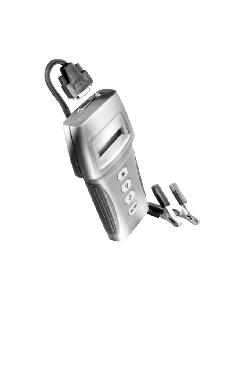
DIGITAL BATTERY ANALYZER
The Professional Digital Battery Analyzer is a hand held diagnostic tool used to
test 6 volt and 12 volt lead-acid type batteries from 50 to 2000 Cold Cranking
Amps (CCA). Most automotive, lawn and garden, motorcycle, marine, heavy
truck, and off road equipment batteries can be tested with this unit. The analyzer will test partially charged batteries provided enough battery charge exists
to power the analyzer. The battery must be charged to 5.5 volts minimum for
the analyzer to operate.
User prompts displayed on the LCD guide the testing process. Test results are
clearly displayed on the LCD after testing is completed. Test results consist of
the following: Battery voltage, available power in CCAs and battery condition
indication. The battery may remain connected to the vehicle, as long as the
vehicle electrical system does not interfere with testing. The power cable is
detachable for easy storage or replacement.
An internal 9 volt battery supplies power to allow viewing of test results from
memory or to enable the print function; an infrared printer interface sends test
results to an available external printer for hard copy reports.
When the analyzer is using internal power, the following functions are available:
View Test Results, Print Test Results, and Voltmeter.
The analyzer is protected from accidental reverse connection to the battery.
VEHICLE PREPARATION
BEFORE TESTING, READ ALL SAFETY GUIDELINES.
Key OFF, engine OFF.
Disconnect all battery chargers! Battery cannot be tested while being charged.
In all multiple battery systems, all batteries must be tested separately. Batteries
connected in parallel must be disconnected. Only batteries in series may
remain connected during testing, see diagram below:
TO VEHICLE
+ -
POS NEG
Batteries in Series: All batteries are connected from the negative (-)
terminal of one battery, to the positive (+) terminal of the other. Only the
negative terminal of the first battery and the positive terminal of the last
battery are to be connected to the vehicle. Any number of batteries may be
connected in a series. However, each battery must be tested separately.
All other types of multiple connections must be disconnected from each other.
If the battery is connected to the vehicle, remove all electrical loads.
Battery connections must be clean and have good contact for proper test results.
Install terminal stud adapters (not included) on side post batteries. Terminal stud
adapters are available at most automotive parts stores.
+ -
POS NEG
2
TO VEHICLE
+ -
POS NEG
Page 3

HOOKUP
Connect the power cable to analyzer.
Connect the black clamp to the negative (-) terminal of the battery.
Connect the red clamp to the positive (+) terminal of the battery.
Make sure both sides of each clamp make good contact with the battery
terminals. If required, rock the clamps back and forth to improve connection.
If the analyzer does not power up, check the power cable at the analyzer and
the connections to the battery. Also, verify that the battery is charged to a
minimum of 5.5 volts. If the battery is below 5.5 volts, disconnect the analyzer,
and charge the battery.
Follow battery charger manufacturers instructions for proper battery charging
procedures.
Disconnect the charger, then hook up the analyzer. If the analyzer still does not
power up, the battery is not taking a charge and should be replaced.
WARNING:
It is dangerous to attempt to charge a battery with a bad cell.
ANALYZER SETUP
1. Select the language.
The analyzer is factory set to the English language. To change languages
(English, Spanish, French, German, Italian, Swedish, or Dutch), select Analyzer
Setup and then Language from the menu. Use the UP/DOWN arrow keys to
move the pointer next to the appropriate selection and press the \ÿkey.
2. Select the battery CCA measurement standard.
The battery analyzer is factory set to the SAE measurement standard that rates
vehicle batteries sold in the U.S. To select another battery measurement
standard (SAE, DIN, IEC, EN, or BCI), select Analyzer Setup and then CCA
Standard from the menu. Use the UP/DOWN arrow keys to move the pointer
next to the appropriate selection and press the \ÿkey to set the CCA standard
of measure.
3. Adjust the Display.
To change the contrast of the LCD display, select Analyzer Setup and then
Adjust Display from the menu. Use the UP/DOWN arrow keys to change the
screen contrast and press the \ÿkey to set.
4. Select °Celsius or °Fahrenheit.
The analyzer is factory set to display temperature in degrees °F. To change
temperature display, select Analyzer Setup and then choose °C/°F from the
menu. Use the UP/DOWN arrow keys to move the pointer to the desired temperature units and press the \ÿkey to set.
3
Page 4

BATTERY TESTING
1. Select Battery Test and press \ÿkey to begin testing.
The analyzer will check for bad cell(s), excess voltage, and sufficient charge to
run an accurate test. If any of these checks fail, one of the following messages
will be displayed and testing is stopped.
BAD CELL
Indicates that there is a shorted or defective cell in the battery and the
battery needs to be replaced.
VOLTAGE TOO HI
Make sure: No battery chargers are hooked up.
Engine is not running.
You are testing a 6 or 12 volt battery.
Two 12 volt batteries in series (24V) are being tested
individually.
CHARGE & RETEST
Indicates the battery is too low to test and needs to be charged before it
can be tested. If the battery has been charged and continues to give this
result, it is BAD and needs to be replaced.
2. Enter the battery CCA rating.
Use the UP/DOWN arrow keys to change the CCA number of the battery to be
tested. Press and hold arrow key down for rapid scrolling. Once the correct
number is displayed, press the \ÿkey to continue.
NOTE: Do not be confused by CA rating. Use the CCA rating. To convert CA
or MCA (Marine) to CCA, multiply CA or MCA by 0.8.
ENTER CCA: 600
Press
3. Select test based on battery temperature.
Use the UP/DOWN arrow keys to move the pointer next to the appropriate
selection. Press \ÿkey to make selection. Use Batt Above 32°F selection
when the battery actual temperature is above 32°F (0°C). Use Batt Below 32°F
selection when the batterys temperature is 32°F (0°C) or lower.
®Batt Above 32°F
\
To Cont.
Batt Below 32°F
4
Page 5

4. Testing process.
Once the temperature range has been selected, the remaining battery tests
will be start automatically.
TESTING
✼✼ Please Wait ✼✼
After a short period, the analyzer displays the battery condition. After displaying the battery condition test results, the analyzer determines the battery
state-of-charge. Below are the possible results and their meaning:
GOOD BATTERY
Indicates that the battery is good and ready to be returned to
service.
GOOD-RECHARGE
Indicates that the battery is good but needs to be charged before
returning it to service.
REPLACE BATTERY
Indicates the battery is bad and needs to be replaced. Before replacing
the battery, check the following:
Battery clamps had good connection on both sides of clamp during
test. If not, correct connections and retest.
If the battery was hooked up to the vehicle during testing perform the
following steps:
- Disconnect the vehicle from the battery.
- Clean battery posts or terminals.
- Reconnect analyzer and retest.
- If you still get Replace Battery - the battery is bad and needs to be
replaced.
CHARGE & RETEST
Indicates the battery is too low to test and needs to be charged before
it can be retested. If the battery has been charged and continues to
display Charge/Retest, the battery is BAD and needs to be replaced.
SURFACE CHARGE
Indicates that a surface charge exists and should be removed before
retesting the battery. Turn on the vehicle headlights for 60 seconds,
then off. Wait 60 seconds for battery to stabilize (some batteries may
require additional time). Hook up and retest.
5
Page 6

BATTERY TESTING (Contd)
After all tests are complete the battery voltage and state-of-charge in CCA (Cold
Cranking Amps) are displayed on the bottom line of the display as shown in the
sample below. This is the battery available power at its present temperature and
state of charge.
GOOD BATTERY
12.60V 1025 CCA
NOTE: A flashing asterisk (*) next to CCA reading indicates that vehicle noise
was detected during an in-vehicle battery test. The engine and all accessory
loads must be turned off. If the problem remains, disconnect battery from the
vehicle and retest.
If a CCA reading higher than 2000 (analyzer maximum limit) is measured, 2000
and OVER will alternate on the display. If a CCA reading lower than 50 (analyzer
minimum limit) is measured, 50 and UNDER will alternate.
A new battery, when fully charged and at 70°F (21°C), will have a CCA rating that
is greater than the CCA rating on the battery label.
6
Page 7

INTERNAL BATTERY POWER
To power the analyzer from the internal 9V battery, press and hold the ON/
OFF key until text is displayed, and release. If the analyzer does not power
up, replace the 9V battery.
To replace the 9V battery, remove battery cover screw on the back of the
analyzer and slide cover off.
When not in use, and left ON, the analyzer will shut off automatically.
NOTE: The display backlight will not come on when the analyzer is being
powered by the internal 9V battery.
VIEW TEST RESULTS
Each time a test is performed, the previous test results are replaced with the
new results. The analyzer is not required to be connected to an external
battery. To view test results, press the ON/OFF key, select View Data from
the menu and press theÿ\ÿ
key.
PRINT TEST RESULTS
The analyzer has an infrared data link output compatible with an available
Hewlett-Packard model HP 82240B portable thermal printer. Test results
stored in memory may be printed at any time. The analyzer is not required to
be connected to an external battery. To print test results, press the ON/OFF
key, select Print from the menu. Aim the infrared emitter located on the top
of the analyzer at the printer infrared receptor, and press theÿ\ÿ
key.
VOLTMETER FUNCTION
When powering the analyzer from the vehicle battery, voltage can be read.
Select Battery Voltage from the menu and press the \ÿkey.
To use the analyzer as a voltmeter when powering from the 9V battery, select
Voltmeter from the menu and press the
voltage reading. For example, use the optional accessory probes to read
voltage at starting/charging components.
CAUTION: DO NOT CONNECT THE ANALYZER TO VOLTAGE GREATER
THAN 30 VDC OR THE ANALYZER MAY BE DAMAGED.
\ÿÿ
key. The analyzer displays the
7
Page 8

Safety Guidelines For Working on Vehicles:
Always wear approved eye protection.
Always operate the vehicle in a well-ventilated area. Do not inhale exhaust
gasesthey are very poisonous!
Always keep yourself, tools, and test equipment away from all moving or hot
engine parts.
Always make sure the vehicle is in Park (automatic transmission) or Neutral
(manual transmission) and that the parking brake is firmly set. Block the
drive wheels.
Never lay tools on vehicle battery. You may short the terminals together,
causing harm to yourself, the tools, or the battery.
Never smoke or have open flames near vehicle. Vapors from gasoline and
charging batteries are highly flammable and explosive.
Never leave vehicle unattended while running tests.
Always keep a fire extinguisher suitable for gasoline/electrical/chemical fires
handy.
Always turn ignition key OFF when connecting or disconnecting electrical
components, unless otherwise instructed.
Keep away from engine cooling fan. On some vehicles, the fan may start up
unexpectedly.
Always follow vehicle manufacturers warnings, cautions, and service proce-
dures.
©2001
Printed in USA
0002-000-2345
8
 Loading...