


X1130P
Acer X1130P, X1130PA, X1230PK, X1230P, X1230PA Schematic
...
1
Projector Service Manual
Model : X1130P, X1130PA, X1230PK,X1230P,
X1230PA, X1237
Version: Rev3
First Edition (Jul. 2009)
RESTRICTIONS ON USE OF MATERIALS
:

2
Index
REVISION LIST .................................................................................................................... 3
CHAPTER 1 SYSTEM SPECIFICATION ......................................................................... 4
Product Specification.................................................................................................................... 4
Electrical Specification............................................................................................. 11
Power Supply Specification..................................................................................... 15
System Block Diagram ............................................................................................................... 16
Product Overview........................................................................................................................ 17
CHAPTER 2 SYSTEM UTILITIES.................................................................................. 21
Firmware Upgrade SOP............................................................................................................. 21
Method to enter factory menu ................................................................................................... 29
EDID Upgrade SOP.................................................................................................................... 30
Serial Number Upgrade SOP.................................................................................................... 33
How to Change Model name..................................................................................................... 35
CHAPTER 3 SYSTEM DISASSEMBLING AND REPLACEMENT................................36
Main Unit Disassembling............................................................................................................ 36
Module Assembly Key Point - Optical Engine ........................................................................ 41
Module Assembly Key Point – Mechanical ............................................................................. 54
CHAPTER 4 TROUBLESHOOTING.............................................................................. 71
System Analysis .......................................................................................................................... 71
Optical Problems Checking Items ............................................................................................ 72
Power Supply Problems Checking Flow ................................................................................. 74
LED Messages Definition........................................................................................................... 75
Error Count Messages Definition.............................................................................................. 76
RS232 Connection...................................................................................................................... 77
Adjustment / Alignment Procedure........................................................................................... 79
CHAPTER 5 FRU LIST .................................................................................................. 84
Exploded Diagram....................................................................................................................... 84
Module 1 – Total Exploded View............................................................................................... 84
Module 2 – ASSY UPPER CASE ............................................................................................. 86
Module 3 – ASSY LOWER CASE ............................................................................................ 87
Module 4 – ASSY FRONT CASE ............................................................................................. 88
FRU List........................................................................................................................................ 89
APPENDIX A - CODE LIST: IR / RS232 / DDC DATA........................................................ 94
1. Remote Control Code: ........................................................................................................... 94
2. RS-232 Command Code ....................................................................................................... 96
3. DDC Data................................................................................................................................. 98
3
Revision List
Version
Release
Date
Revision History
Vendor
Model
Name
Rev0 2009.07.16
First Release
Rev0 2009.07.20
Modify FRU List—service lamp P/N
Rev0 2009.07.27
(P.5) Modify SPEC : Projection Offset = 120% ±5%
Rev1 2009.07.29
Add X1230PK different part :
(1) Ch1- SPEC,
(2) Ch3- Disassembly process, Module Assembly Key Point
(3) Ch4- alignment procedure
(4) Ch5-FRU List
(5) Appd. A- DDC table
Rev2 2009.09.11
Add X1130PA different part :
(1) Ch1- SPEC,
(2) Ch3- Disassembly process, Module Assembly Key Point
(3) Ch4- alignment procedure
(4) Ch5-FRU List
(5) Appd. A- DDC table
Rev3 2009.09.23
Add X1230P, X1230PA, X1237 different part
(1) Ch1-SPEC
(2) Ch2-“How Change Model Name” for X1230P/X1230PA/X1237
(3) Ch3- Disassembly process
(4) Ch4-Adjustment / Alignment Procedure
(5) Ch5-FRU List
(6) Appendix A-Remote Control Code
(7) Appd. A- DDC table

4
Chapter 1 System Specification
Product Specification
1.0 Optical Performance
2.0 Image Quality
3.0 Mechanical Specification
4.0 Packaging
5.0 Thermal Specification
6.0 Environmental
7.0 Regulatory
8.0 Reliability
9.0 Power Requirements
10.0 Panel Specification
11.0 Compatibility
12.0 Image Interface
13.0 Control Interface
14.0 User Interface
5
1.0 Optical Performance
Tested under 60” (diagonal) image size with Wide
projection lens position unless other specified.
1.1 ANSI Brightness
X1130P/X1130PA/X1230P : Minimum 2000 Lumens
X1230PK/X1230PA : Minimum 1840 Lumens
X1237 Minimum 2400 Lumens
1.2 Brightness Uniformity
1.2.1 ANSI Uniformity
Minimum 55%
1.2.2 JBMA Uniformity Minimum 75%
1.2.3 Upper-Down
unbalance
0.5~2
1.2.4 Left-Right
unbalance
0.6~1.67
1.3 Contrast Ratio
1.3.1 ANSI Contrast Minimum 150:1
1.3.2 FOFO Contrast
without APM
X1130P/X1130PA/ X1230P/ X1237: Minimum 1600:1
X1230PK/X1230PA : Minimum 1100:1
1.3.3 FOFO Contrast with
APM
X1130P/X1130PA/ X1230P/ X1237: Minimum 2100:1
X1230PK/X1230PA : Minimum 1200:1
1.4 Light Leakage
1.4.1 Light Leakage in
Active Area
<0.5 lux compared to center point within 60” (Diagonal at
2.3m, Wide) image size. Note: This light leakage in Active
area is only described as the spot light with obvious shape.
It is not included the uniformity difference of the projector for
black pattern.
1.4.2 Light Leakage out of
Active Area
(Except DMD Defect)
<0.5 lux with 60”~80“(Diagonal at 2.3m, Wide) image size
1.5 Color
X Y
1.5.1 White 0.314±0.04 0.377±0.04
1.5.2 Red 0.647±0.04 0.341±0.04
1.5.3 Green 0.344±0.04 0.587±0.04
1.5.4 Blue 0.139±0.03 0.090±0.03
1.6 Color Uniformity X Y
1.6.1 White 0.040 0.040
1.6.2 Red 0.040 0.040
1.6.3 Green 0.040 0.040
1.6.4 Blue 0.040 0.040
1.7 Color Gamut Typ 60% compare NTSC
2.0 Image Quality
2.1 Throw Ratio 52.5”±3% Diagonal at 2m, Wide
2.2 Zoom Ratio (tolerance
applied)
1.1±2%
2.3 Distortion
2.3.1 Keystone Distortion <1.0%
2.3.2 Vertical TV
Distortion
<1.0%
2.4 Projection Offset 120% ±5%
2.5 Focus Range
2.5.1 Visible Range 1~8 m
6
2.5.2 Clearly Focus
Range
1.5~6 m(Spec. defined as item 2.6)
2.6 Focus
2.6.1 区 Pattern
(1) If pattern can be uniformly focused (not worse than Limit
Sample), then pass!
(2) If it’s difficult to judge, then check 2.6.2
2.6.2 Defocus and Flare
X1130P :
Defocus: R<=3.0; G<=3.0; B<=3.0 pixel
Flare: R<=3.5; G<=3.5; B<=3.5 pixel
Slight flare is not counted as flare.
X1130PA/X1230PK/X1230P/X1237/X1230PA:
Defocus: R<=3.5; G<=3.0; B<=3.0 pixel
Flare: R<=4.0; G<=4.0; B<=4.0 pixel
Slight flare is not counted as flare.
2.6.3 Focus unbalance
Adjust focus from near to far until one corner clear,
difference less than 50 cm
Center of
49”diagonal area
All other area
R-G <2/3 <1
G-B <2/3 <1
2.7 Lateral Color
R-B <1 <1
2.8 Image Quality
2.8.1 DMD Image Quality
2.8.2 Image Imperfection
2.9 Lamp Type Philips UHP 185W-160W 0.9 E20.9 with VIDI
3.0 Mechanical Specification
3.1 Dimensions 264 x 225 x 95 mm (L x W x H)
3.2 Weight <2350g
3.3 Security Slot Kensington compatible slot 150N break away force
3.5 Lens Cover Lens Cover
3.6 Feet
Fast adjustable foot in front, Adjustable foot and Fixed foot
in rear. foot Tilt:0-6∘,right/left: +2.2 /∘ -0.5
∘
4.0 Packaging Detail refer to following Packing section
4.1 Outside Dimensions 360 x 180 x 297mm (L x W x H)
4.2 Weight <4100g
4.3 Transportation
40 feet container 2688 sets, 20 feet container 1344 sets
By air 48 sets
5.0 Thermal Specification Mechanical component temperature at ambience 0~35℃
5.1 Surface held or
touched for short periods
Metal < 65°C; Plastic<85°C
Metal Plastic
5.2 Surface which may be
touched
<65°C <85°C
5.3 Exhaust Air
<95°C
6.0 Environmental
Operating
0~35°C, without condensation
6.1 Temperature
Storage -30~65°C, without condensation
Operating
10~90%RH, without condensation
6.2 Humidity
Storage 10~90%RH, without condensation

7
Typical
X1130P/X1130PA /X1230P/X1237:
Normal mode: 34dBA @ 23±2°C, CW x2 speed
Eco mode: 29dBA @ 23±2°C, CW x2 speed
Normal mode: 36dBA @ 23±2°C, CW x3 speed
Eco mode: 31dBA @ 23±2°C, CW x3 speed
X1230PK/X1230PA :
Normal mode: 36dBA @ 23
±
2°C, CW x2 speed
Eco mode: 31dBA @ 23
±
2°C, CW x2 speed
Normal mode: 38dBA @ 23
±
2°C, CW x3 speed
Eco mode: 33dBA @ 23
±
2°C, CW x3 speed
6.3 Audible Noise Level
Maximum
X1130P/X1130PA/X1230P/X1237 :
Normal mode: 36dBA @ 23±2°C, CW x2 speed
Eco mode: 31dBA @ 23±2°C, CW x2 speed
Normal mode: 38dBA @ 23±2°C, CW x3 speed
Eco mode: 33dBA @ 23±2°C, CW x3 speed
X1230PK/X1230PA :
Normal mode: 38dBA @ 23
±
2°C, CW x2 speed
Eco mode: 33dBA @ 23
±
2°C, CW x2 speed
Normal mode: 40dBA @ 23
±
2°C, CW x3 speed
Eco mode: 35dBA @ 23
±
2°C, CW x3 speed
6.4 Altitude
Operating:
1. 12,000 feet @ 25°C (3.5 hours)
2. Altitude Ramp rate: <= 3500 feet per minute (1 hour)
Non-operating:
40,000 feet @ -30 °C (1 hour)
Safety
CB, GS, cTUVus, PSE, CCC
EMC CE, FCC, VCCI
7.0 Regulatory
ESD
8.0 Reliability
8.1 MTBF 25000 hours except Lamp
8.2 Lamp Lifetime
Normal : 3000 hours
Eco: 4000 hours
(50% of Projector will have 50% initial minimum brightness)
9.0 Power Requirements Adhere to “Power Supply Specification” section
9.1 Power Supply (Normal) VAC 100 – 240 (50/60Hz),
Typical 280W Max.
9.2 Power consumption
Standby 1W Max.
9.3 Power Connector IEC-06
10.0 Panel Specification
10.1 Type
X1130P/
X1130PA
: 0.55” SVGA 2xLVDS Series 450 DMD
X1230PK/X1230PA : 0.55” XGA 2xLVDS Series 450 Super
value DMD
X1230P/X1237:0.55” XGA 2xLVDS Series 450 DMD
10.2 Pixels
X1130P/X1130PA : H: 800 X V: 600
X1230PK/ X1230P / X1230PA / X1237: H: 1024 X V: 768
10.3 Color Depth 30 Bits (1.07 Billion Colors)
11.0 Compatibility Adhere to “Electrical Specification” section
11.1 PC
PC Compatible 640X480 1024X768, compressed
1600X1200; Composite-Sync; Sync-on-Green
8
11.2 Video
NTSC/ NTSC4.43/ PAL (Including PAL-M, PAL-N)/ SECAM/
PAL60/
11.3 YpbPr
NTSC (480i)/ 480p/ PAL (576i)/ 576p,
HDTV (720p/1080i/1080p)
11.4 DDC EDID 1.3
12.0 Image Interface Adhere to “Electrical Specification” section
12.1 Analog RGB Input
X1130P/X1230PK:
15 pin D-Sub (Female) x 1 (Reserved 2
nd
VGA IN)
G(Y): Video amplitude 0.7/1.0 Vp-p : Impedance 75Ω
RB(CbCr): Video amplitude 0.7 Vp-p : Impedance 75Ω
HD/VD/CS: TTL Level
X1130PA/ X1230P/ X1237 /X1230PA:
15 pin D-Sub (Female) x 2
G(Y): Video amplitude 0.7/1.0 Vp-p : Impedance 75Ω
RB(CbCr): Video amplitude 0.7 Vp-p : Impedance 75Ω
HD/VD/CS: TTL Level
12.2 Video Input
RCA jack (Yellow)
Video amplitude 1.0 V
p-p
: Impedance 75Ω
12.3 S-Video Input
4 pin Mini-Din (Female)
Y: Luminance amplitude 1.0 V
p-p
: Impedance
75Ω
C: Chroma amplitude 0.286 V
p-p
: Impedance
75Ω
12.4 YPbPr Input 15 pin D-Sub (Female) x 1
Y: Luminance amplitude
1.0 V
p-p
: Impedance 75Ω
PbPr/C
b
C
r
: Chroma amplitude 0.7 V
p-p
: Impedance 75Ω
12.5 Analog RGB Output X1130P : None
X1130PA/X1230PK/X1230P/ X1237/ X1230PA :
15 pin D-Sub (Female) x 1 (Only support D-sub 1)
G(Y): Video amplitude 0.7/1.0 Vp-p : Impedance 75Ω
RB(CbCr): Video amplitude 0.7 Vp-p : Impedance 75Ω
HD/VD/CS: TTL Level
13.0 Control Interface
13.1 IR Receiver
IR Receiver x 2 (Front/Top)
Angle: ±0° Distance 0~10m ; ±40° Distance 0~8m
13.2 Serial Connector
RS232 Mini DIN 3pin,
command table adhere to “Electrical Specification” section
13.3 USB Connector
X1130P : None
X1130PA/ X1230PK/ X1230P/ X1237/ X1230PA: Mini USB
TYPE B Terminal for page up/down
14.0 User Interface Adhere to “Electrical Specification” section
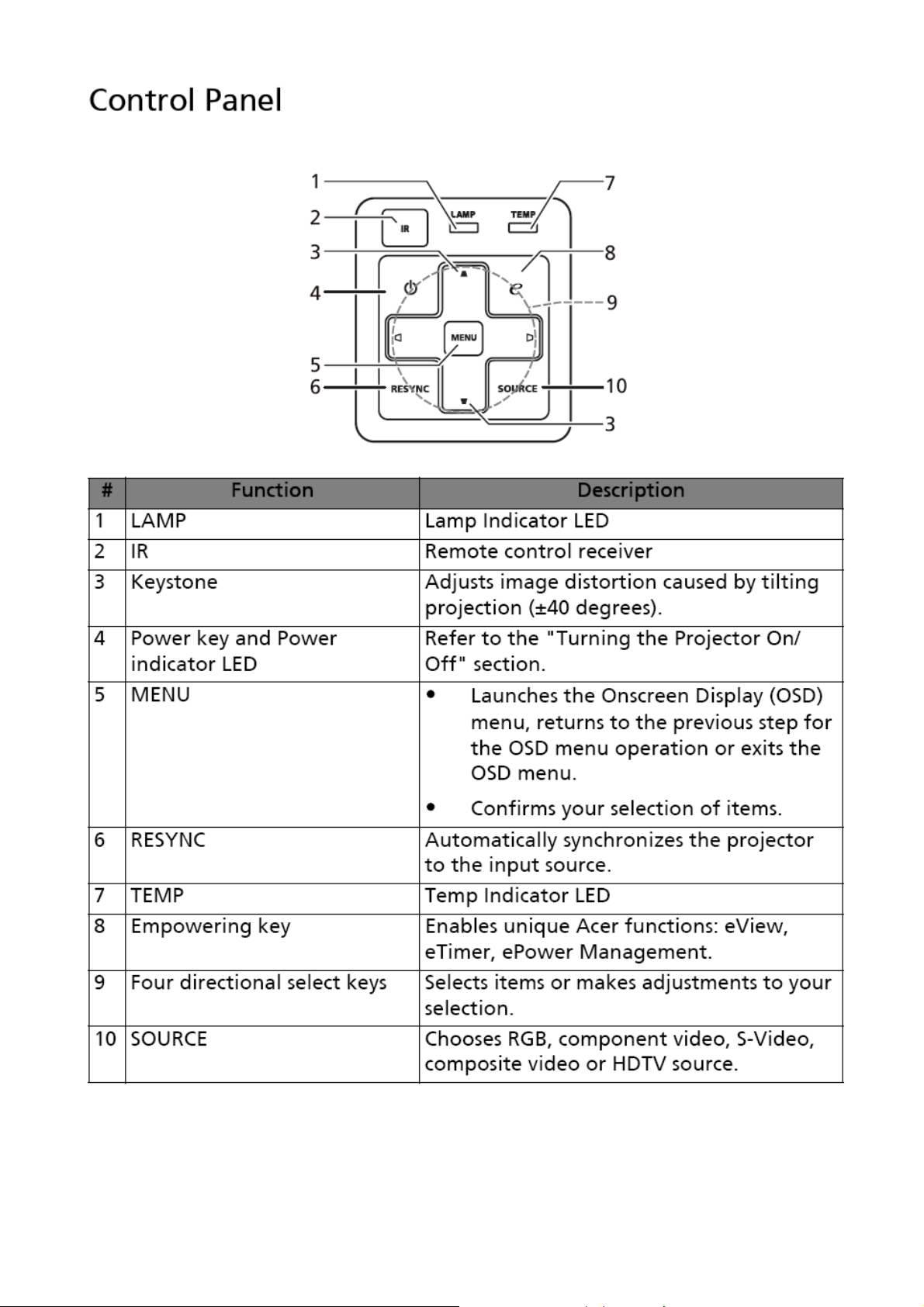
14.1 Operator Keypad
9 Keys:
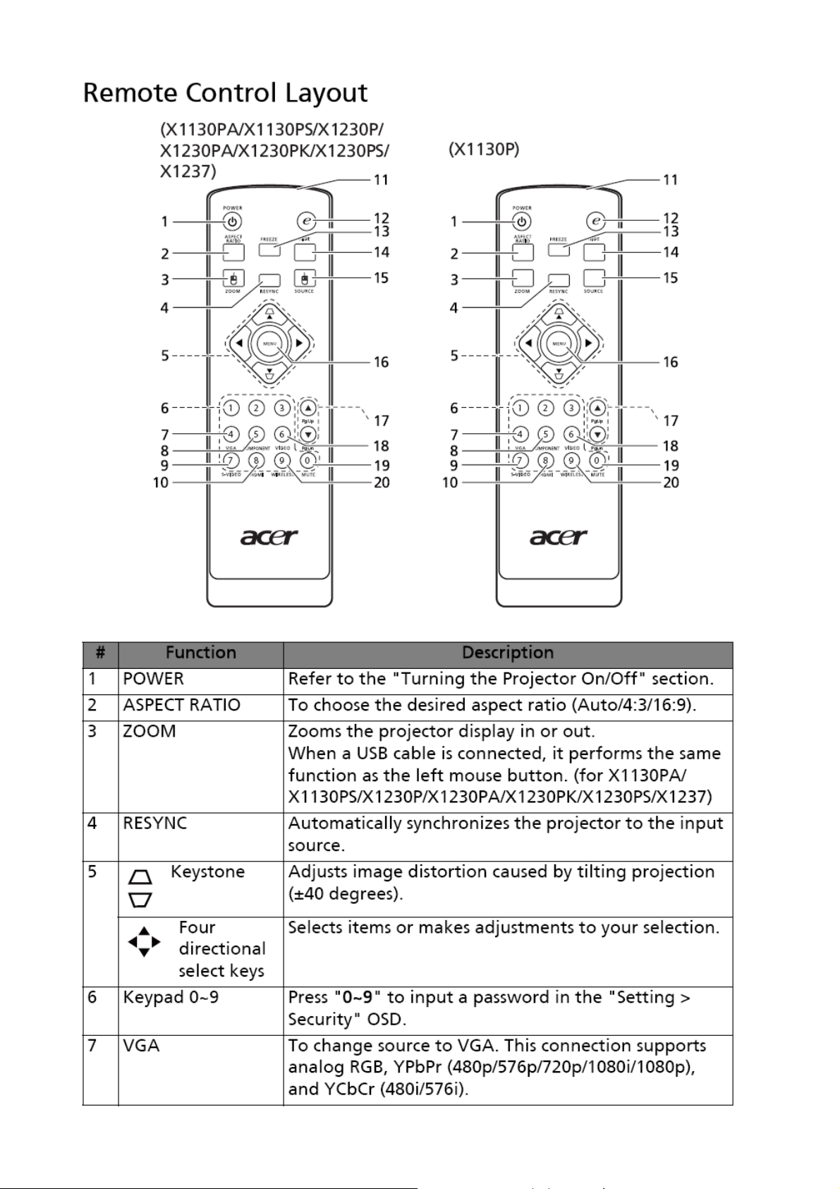
Power ; Source ; Resync ; e ; Menu ; Left ; Right ;
Up(Keystone-) ; Down(Keystone+)
14.2 Indicators
3 LEDs:
Power On/Off Status; Lamp Status; Temperature Status
14.3 Electric Keystone
Manual vertical keystone and adjustable range ±40°
14.4 Auto Ceiling mount
detection
X1130P/X1130PA : None
X1230PK/
X1230P/X1237/ X1230PA: Projector will
auto-detect and project by aligned screen like
auto-keystone effect no matter which projection method
9
(Front, Rear).
15.0 Audio X1130P: None
X1130PA / X1230PK/ X1230P/ X1237/ X1230PA: see below
SPEC
15.1 PC Audio Input X1130PA / X1230PK/ X1230P/ X1237/ X1230PA :
Φ3.5mm stereo mini jack
500mVrms 10 KΩ or more
15.2 Speaker
X1130PA /X1230PK / X1230P/ X1237/ X1230PA:
Speaker 8Ω 2W X 1, Amplifier 1W X1
16.0 Lamp hour
Lamp hour = [Hour used in Normal Mode] + 3/4 *[Hour used
in Eco. Mode]
17.0 Closed Caption (CC)
17.1 CC version CC1/CC2/CC3/CC4
18.0 Instant On
(Running change to phase-in X1130P/X1130PA /X1230PK /
X1230P/ X1237/ X1230PA MP stage)
After turn off projector, there is 120 seconds called “Instant
On stage”. At this stage, user can turn on the projector. Aftet
this stage, projector will cooling for 20 seconds, and all
keypads are not allowed to operate.
19.0 3D Projection
(Running change to phase-in X1130P/X1130PA /X1230PK /
X1230P/ X1237/ X1230PA MP stage)
See below detail description.
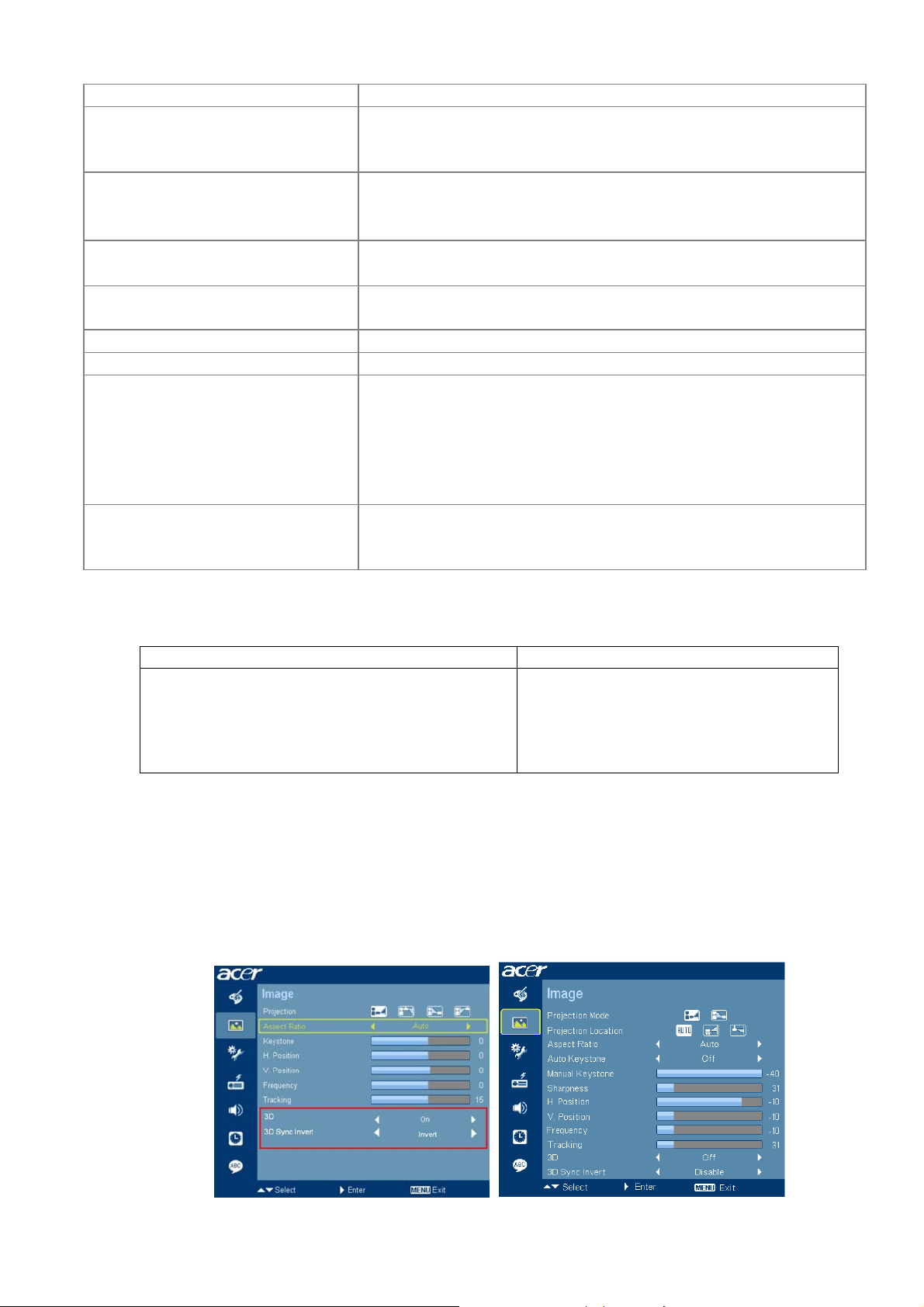
3D Projection :
This function is only for 3D contents and must wear 3D glasses.
TI DDP DDP2430 TI DDP DDP2431
• Does not support FRC (Frame Rate Conversion)
• Can not support HQFS 60Hz 3D source from
DVD which need to go thru FRC
• Can only support 120Hz 3D source from PC
(VGA/DVI/HDMI)
• Support FRC (Frame Rate Conversion)
• Can support HQFS 60Hz 3D source from
DVD which need to go thru FRC
• Can support 120Hz 3D source from PC
OSD :
− Add “3D”, “3D Sync Invert” in Image Page
− “3D Sync Invert” is adjustable when above "3D" is on. Otherwise 反白
− When 3D is enabled, Display Mode(in Color Page) is not adjustable (反白).
− For DDP2430 models : 3D / 3D Sync Invert , only appear for VGA/DVI/HDMI source.
Disappear if other sources.
− For DDP2230/2431 models : no this limitation.

10
Reminder screen :
− Pop-up screen and appear 10 sec in the center of the screen. End-users can press Menu to
exit within 10 sec.
− (1) When 3D enable, this screen will appear after exit OSD menu.
− (2) There has reminder screen if 3D still enable when power on projector.
− Priority : PWD login screen (Security fn is on) Lamp life reminder 3D reminder
Screen Timer and other OSD pup-up fn.
11
Electrical Specification
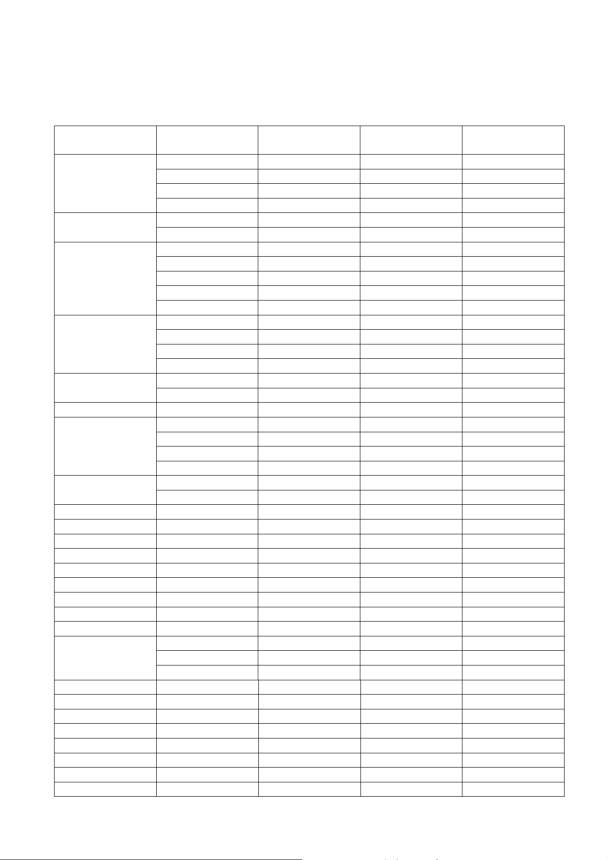
1. Timing Table
The PC timing is as following:
Resolution Mode
Refresh rate
(Hz)
H-frequency
(kHz)
Clock
(MHz)
VGA_60 59.940 31.469 25.175
VGA_72 72.809 37.861 31.500
VGA_75 75.000 37.500 31.500
640 x 480
VGA_85 85.008 43.269 36.000
VGA_70 70.087 31.469 28.3221
720 x 400
VGA_85 85.039 37.927 35.500
SVGA_56 56.250 35.156 36.000
SVGA_60 60.317 37.879 40.000
SVGA_72 72.188 48.077 50.000
SVGA_75 75.000 46.875 49.500
800 x 600
SVGA_85 85.061 53.674 56.250
XGA_60 60.004 48.363 65.000
XGA_70 70.069 56.476 75.000
XGA_75 75.029 60.023 78.750
1024 x 768
XGA_85 84.997 68.677 94.500
SXGA_70 70.012 63.851 94.500
1152 x 864
SXGA_75 75.000 67.500 108.000
1152 x 864 SXGA_85 84.990 77.094 121.500
SXGA_60 60.020 63.981 108.000
SXGA_72 72.000 76.970 134.600
SXGA_75 75.025 79.976 135.000
1280 x 1024
SXGA_85 85.024 91.146 157.500
QuadVGA_60 60.000 60.000 108.000
1280 x 960
QuadVGA_75 75.000 75.000 126.000
1400 x 1050 SXGA+_60 59.978 65.317 121.750
1600 x 1200 UXGA_60 60.000 75.000 162.000
640x480@60Hz
Mac G4 59.940 31.469 25.170
640x480@67Hz
MAC13 66.667 35.000 30.240
800x600@60Hz
Mac G4 60.317 37.879 40.000
832x624@75Hz
MAC16 74.546 49.722 57.280
1024x768@60Hz
Mac G4 60.004 48.363 65.000
1024x768@75Hz
MAC19 75.020 60.241 80.000
1152x870@75Hz
MAC21 75.061 68.681 100.00
WXGA_60 59.870 47.776 79.500
WXGA_75 74.893 60.289 102.250
1280 x 768
WXGA_85 84.837 68.633 117.500
1280 x 720 WXGA_60 60.000 45.000 74.250
1280 x 800 WXGA_60 59.810 49.702 83.500
1440 x 900 WXGA+_60 59.887 55.935 106.500
1680 x 1050 1680x1050_60 59.954 65.290 146.250
1920 x1080 1920x1080_60 60.000 67.500 148.500
1366 x 768 acer_16:9 59.790 47.712 85.500
1024 x 600 acer_timing 60.000 37.500 50.400
640 x 480 VGA_120 119.518 61.910 52.500
12
800 x 600 SVGA_120 119.854 77.425 83.000
1024 x 768 XGA_120 119.804 98.958 137.750
Note:3D timing will phase in after MP when 3D function ready
YPbPr support timing is as following:
Signal format fh(kHz) fv(Hz)
480i(525i)@60Hz 15.73 59.94
480p(525p)@60Hz 31.47 59.94
576i(625i)@50Hz 15.63 50.00
576p(625p)@50Hz 31.25 50.00
720p(750p)@60Hz 45.00 60.00
720p(750p)@50Hz 37.50 50.00
1080i(1125i)@60Hz
33.75 60.00
1080i(1125i)@50Hz
28.13 50.00
1080P@60HZ 67.5 60.00
1080P@50Hz 56.26 50.00
Video, S-Video support timing is as following:
Video mode fh(kHz) fv(Hz) fsc(MHz)
NTSC 15.73 60 3.58
PAL 15.63 50 4.43
SECAM 15.63 50 4.25 or 4.41
PAL-M 15.73 60 3.58
PAL-N 15.63 50 3.58
PAL-60 15.73 60 4.43
NTSC4.43 15.73 60 4.43
2. Characteristics of inputs/outputs
Signal Parameter Min
Type Max
Impedance 75 Ohm
Amplitude 0.7 Volts peak-to-peak
Black pedestal 0 Volts
RDATA
GDATA
BDATA
Pixel Clock 165 M Hz
Impedance 75 Ohm
Amplitude 1 Volts peak-to-peak
Video amplitude 0.7 Volts peak-to-peak
Sync amplitude 0.3 Volts peak-to-peak
Black pedestal 0 Volts
GDATA_SO
G
Pixel Clock 165 M Hz
Impedance 1 K ohm
Amplitude, low level 0 0.8 volt
Amplitude, high level 2.5 5 Volt
HDATA
Frequency 31 93 K Hz
Impedance 1 K ohm
Amplitude, low level 0 0.8 volt
Amplitude, high level 2.5 5 Volt
VDATA
Frequency 48 120 Hz
Amplitude, low level 0 0.8 volt SDADATA
Amplitude, high level 2.5 5 Volt
13
Amplitude, low level 0 0.8 volt SCLDATA
Amplitude, high level 2.5 5 Volt
RXD Amplitude -25 25 Volt
TXD Amplitude -13.2
13.2 Volt
Amplitude, total (video+
sync)
1 Volts peak to peak
Amplitude, video 0.7 Volts peak to peak
Amplitude, sync 0.3 Volts peak to peak
CVBS
Luminance
Impedance 75 ohm
Amplitude 300 m Volts peak to peak CVBS
Chroma
Impedance 75 ohm
Impedance (audio in) 10 Kohm
Amplitude (audio in) 0 0.50
Volts rms
Bandwidth 300H
z
16kH
z
S/N Ratio 40 %
Audio
(for
X1130PA /
X1230PK/
X1230P/
X1237/
X1230PA)
Total Harmonic
Distortion
10 %
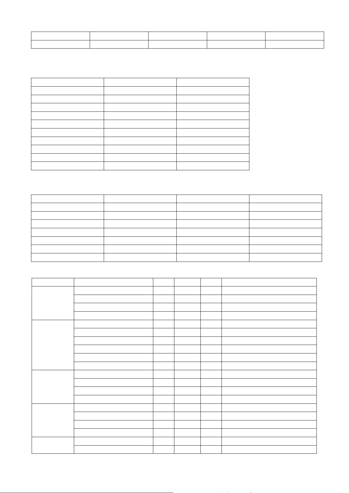
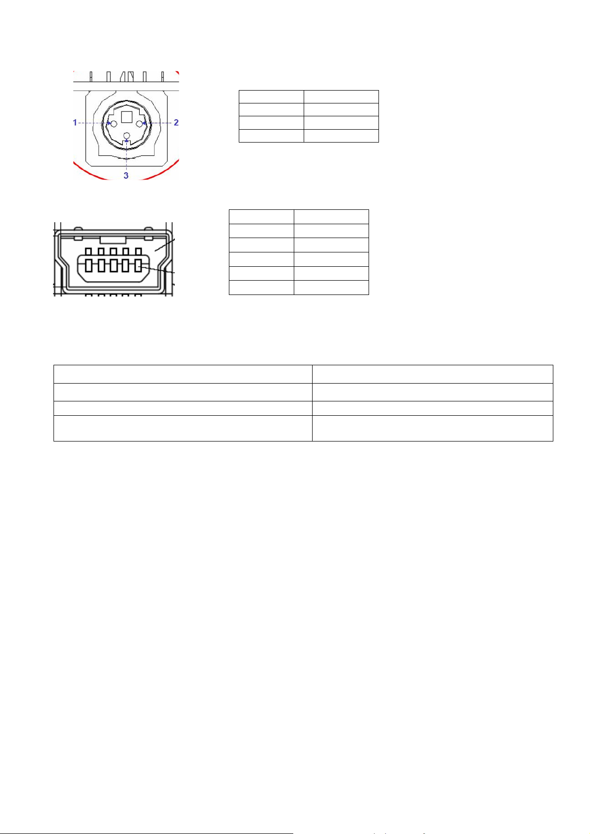
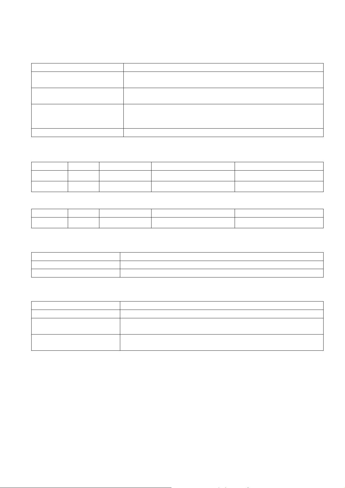
3. Electrical Interface Character
Interface Definition
15 pin definition of the mini D-sub male for DDC2B protocol
1
5
6
10
11
15
Pin
Definition Pin
Definition Pin Definition Pin
Definition
1 Red video
(Pr)
2 Green Video
(Y)
3 Blue Video
(Pb)
4 NC
5 NC 6 Red Video Return
7 Green Video
Return
8 Blue Video
Return
9 DDCP 5V 10 GND 11
GND 12
Bi-directional
data (SDA)
13 Horizontal
Sync
14 Vertical Sync 15
Data clock
(SCL)
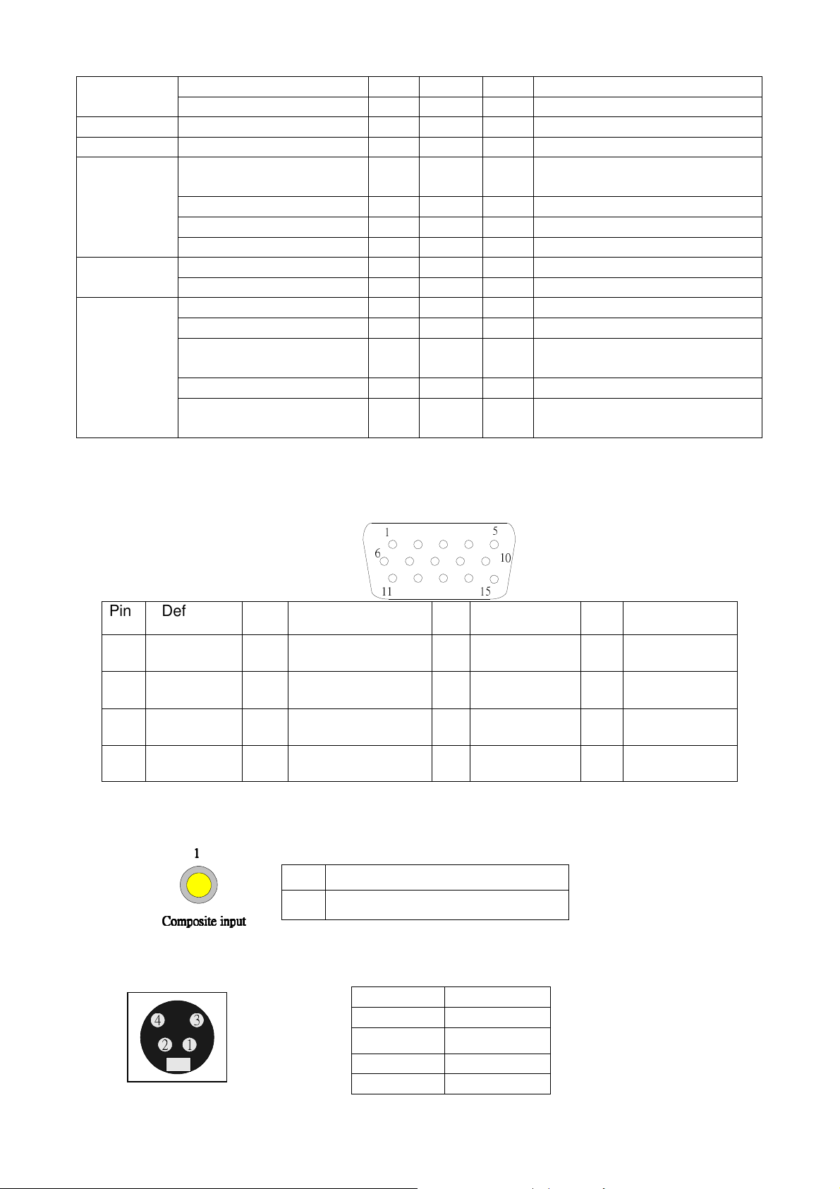
Video Input
S-Video input
Pin Description
1 GND
2
GND
3 Luminance
4 Chroma
Pin
Definition
1 Composite video input
Composite input
Composite inputComposite input
Composite input
1
11
1
2
4
1
3
14
Control Port
Mini USB TYPE B (for X1130PA /X1230PK/ X1230P/ X1237/ X1230PA)
4. Functionality
External Message indicator
Message Occasion
D-sub /Composite Video /S-Video Searching The system does not detect the signal
Input Not Supported The signal is over the specification
Lamp is approaching the end of its useful life in full
power operation. Replacement suggested!
Lamp Hour is at 2970 hours
Pin Description
1 TX
2 RX
3 GND
Pin Description
1 Vbus
2 D-
3 D+
4 ID
5 GND
15
Power Supply Specification
1. Input Power Specification
Specification Description
Input Voltage Range The unit shall meet all the operating requirements with the
range 90 ~ 264 VAC
Frequency Range The unit shall meet all the operating requirements with an input
frequency range 47 Hz ~ 63 Hz
Power Consumption Normal operation: 280W (Max)
standby mode: < 1W (loop through is disabled), at
100~240VAC
Regulation Efficiency 85 % (typical) measuring at 115Vac and full load
2. Output Power Requirement
The power supply can provide DC 12V output as below:
NO. Voltage
Regulation Load Current Range Ripple & Noise
1
+12 V
±5 %
0.15 A ~ 2.5 A 120mV/240 mV
2
+5 V
±5 %
0.04 A ~ 0.5 A 50mV/100 mV
The power supply can provide DC 380V output as below:
NO. Voltage
Range Load Current
1
380 V
370~400V 0.5 A TYP.
3. Lamp Power specifications
Specification Description
Applicable Lamp Philips Normal 189W, ECO 163W AC operation
Starting pulse from Ignitor 2.5KV
4. Power Protection
Item Criteria
Short protection No damage
OVP 16Vdc Max@12V
6.5Vdc Max@5V
OPP DC-DC 130~250%
PFC 130~160%
5. Surge test: Meet EN61000-4-5
L
N 1KV, L, N PE 2KV, Criteria B
Electrical Fast Transients (EFT):Meet EN61000-4-4
1 KV, Criteria B
7. Voltage Dips: Meet EN61000-4-11
>95% reduction for 0.5 periods, Criteria B
Harmonic current test: Meet EN61000-3-2
16
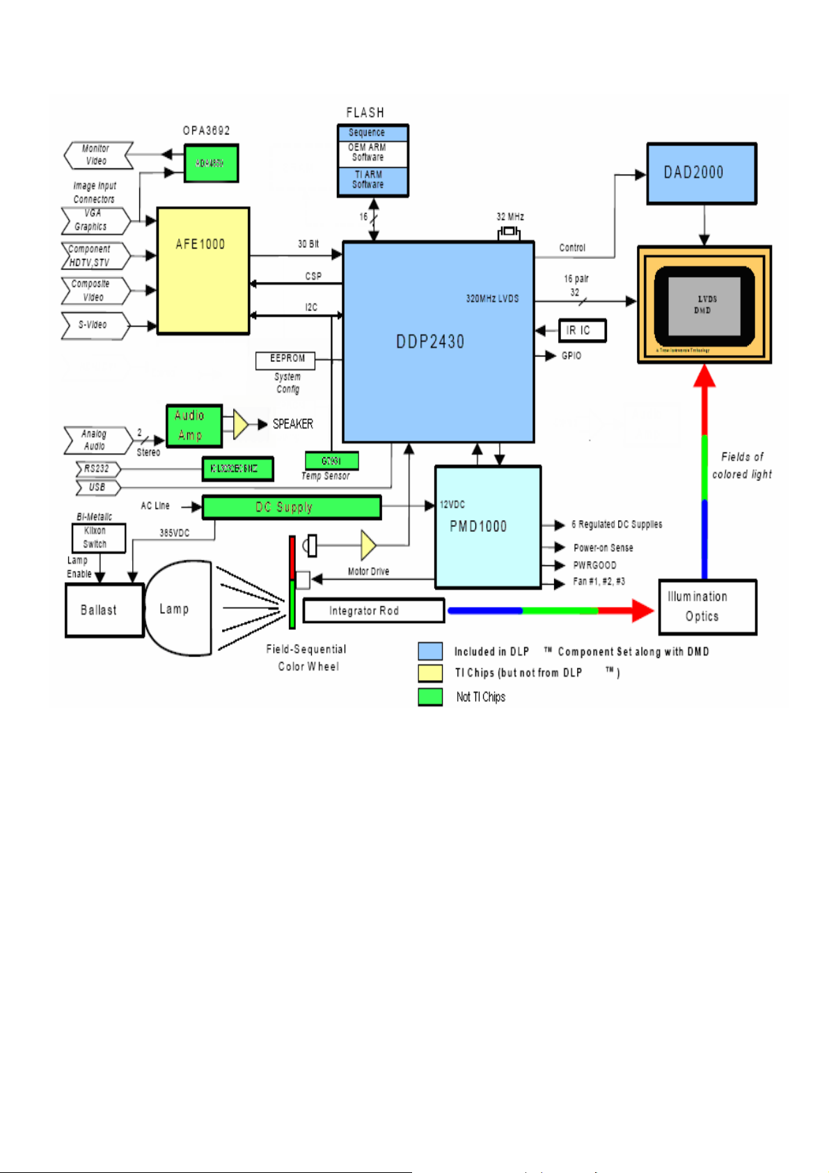
System Block Diagram
17
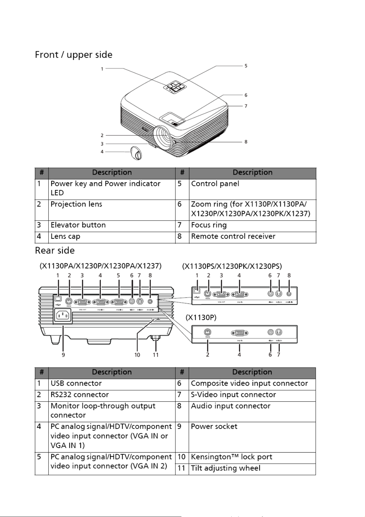
Product Overview
18
19

20
21
Chapter 2 System Utilities
Firmware Upgrade SOP
Basic Operating
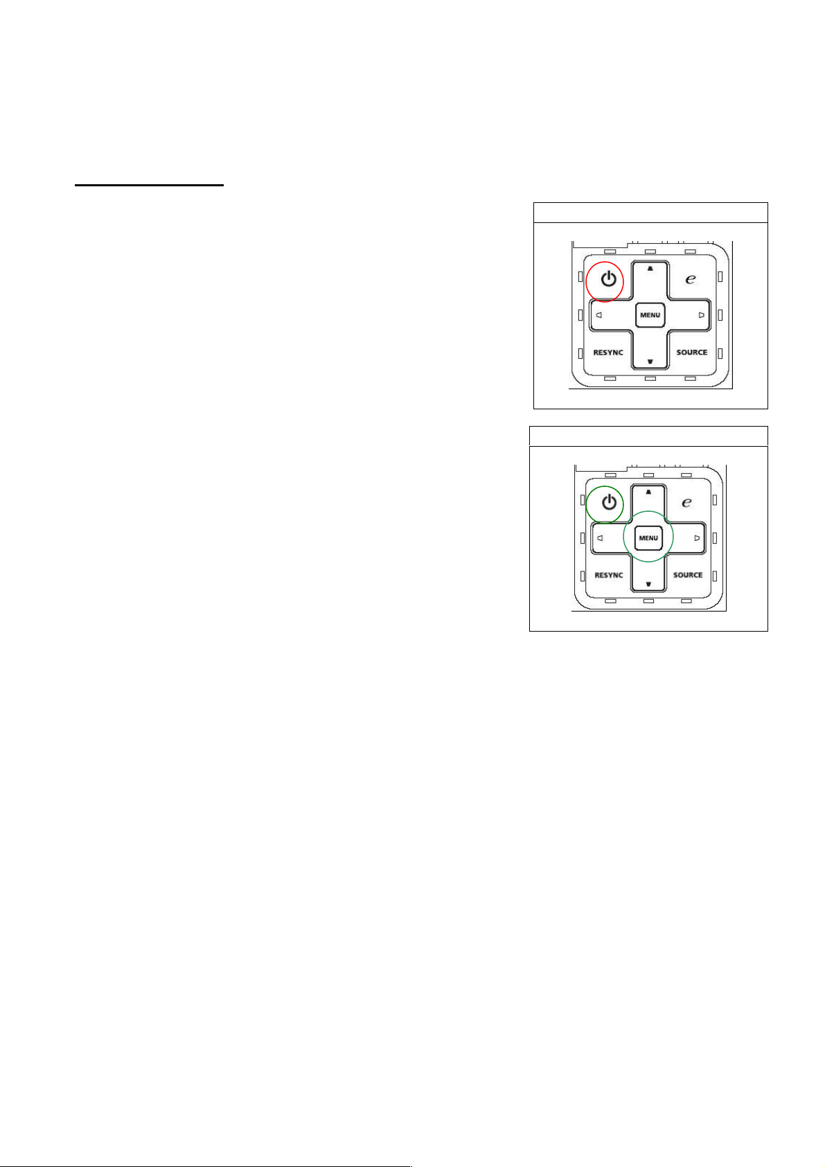
Standby Mode:
::
:
When standby mode, system power consumption will
be less than 1 Watt.
If user wants to enter this mode, user can just plug in
power cord. Power, Lamp, Temp LED will show Red for
1 sec then power LED show red continuously as the
figure shown. When the power LED shows Red, it means
system is ready for standby.
Besides, user can press power key to turn on projector
after plugging in power cord when power led is red.
Download Mode:
::
:
This mode is applied for Download firmware.
If operator wants to enter this mode, he should press
and hold keypad Power and Menu together, then plug
in power cord. Release the two keypads. Power,
Lamp, Temp LED will show red light continuously. In
download mode, you can use DLP composer to download
new firmware and power LED will show purple while
downloading.
Download WT6702 MCU Code:
::
:(in Low-Power 1 Watt Standby)
System needs a few sec to download WT6702 MCU automatically.
When Downloading:Temp LED will show red.
When Download Success:System will go back Low-Power standby mode and Power LED
will show red.
When Download Fail: Lamp LED will show red.
<Notice:Do NOT interrupt power when downloading MCU Code.>
Standby Mode
Download Mode
22
DLP Composer LIte Installation Process
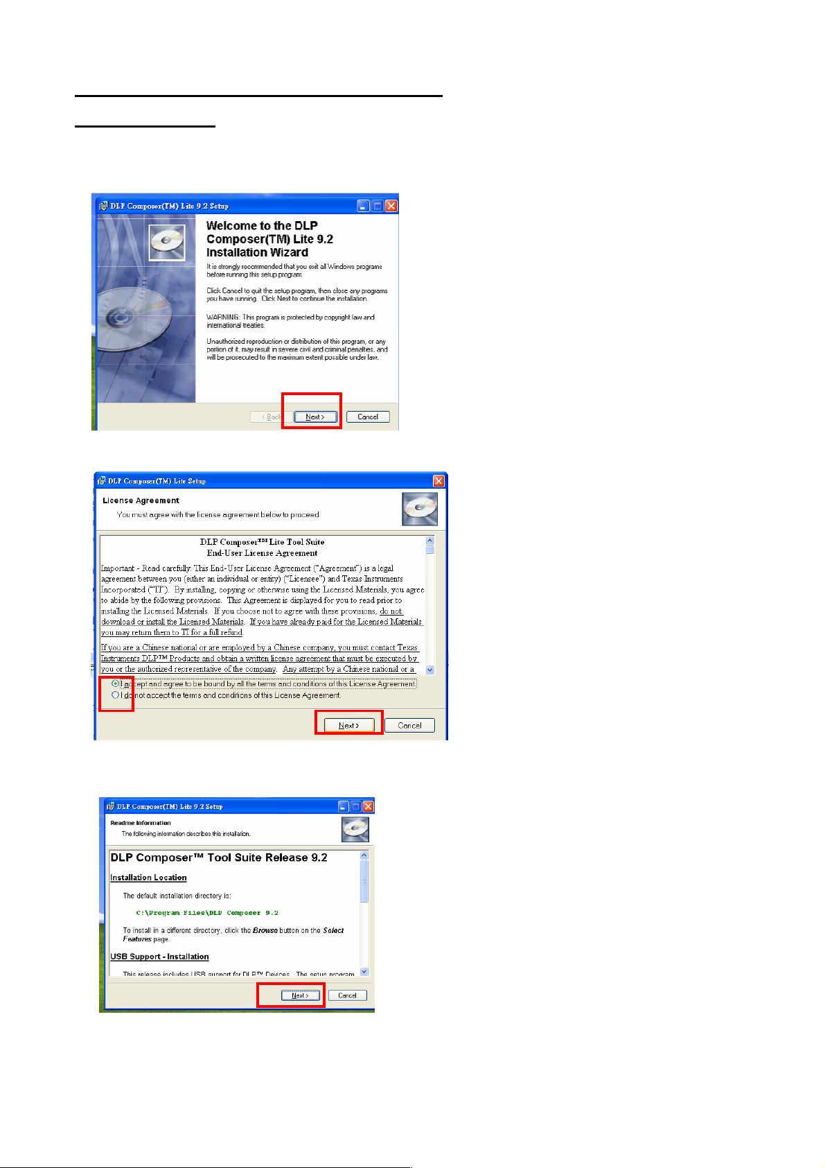
(1) Installation
1. Double click the Setup file for DLP Composer Lite(to unzip “TI Download Tool V1.1 (for
DDP243x).rar” to start to install program.
2. When the Installation Wizard appears, click “Next”.
3. Select to accept the License Agreement, than click “Next”
4. Click “Next” in the following steps to continue installation process.
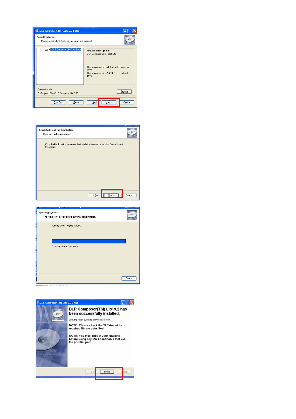
23
Note:
The default installation directory is:
C:\Program Files\DLP Composer Lite9.2
If you want to install to a different directory (perhaps
alongside a prior release of DLP Composer™ Lite),
click the "Browse" button on the "Select Features"
page.
5. When finishing installation, click “Finish”, and then restart your computer to complete the
installation process.
24
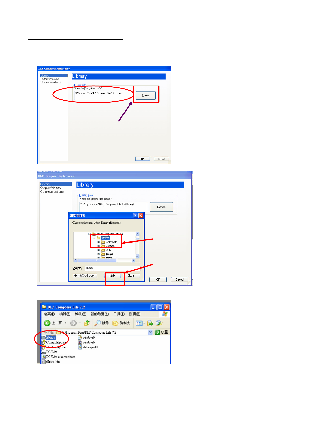
(2) Setting for your first use
Select Library:
1. When start to use this program to download at first time, you need to check if the library
folder is existed under the path of Library.
2. Check if there are library files in the assigned path. If not, unzip the library file into the path.
Click
Click Click
Click
“
““
“
Browse
BrowseBrowse
Browse
”
””
”
to
to to
to
select
select select
select
path for library files
path for library filespath for library files
path for library files
Click the
Click the Click the
Click the
library
librarylibrary
library
folder to assign
folder to assign folder to assign
folder to assign
the path.
the path.the path.
the path.
Then Click
Then Click Then Click
Then Click “
““
“OK
OKOK
OK”
””
”.
..
.
25
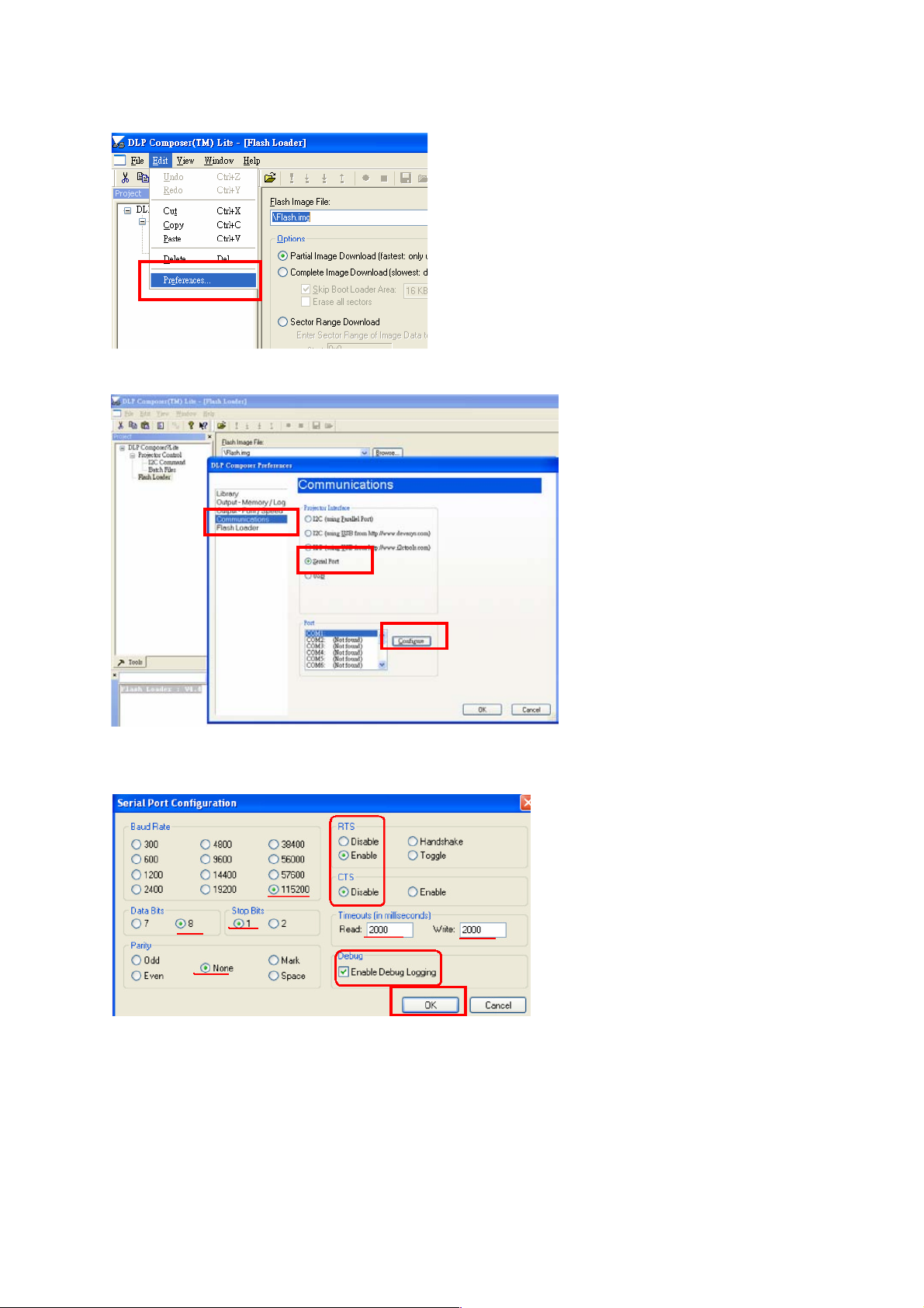
Set communication (for download by RS232):
1. Select “Edit”->”Preference”.
2.
Select “Communications”-> “Serial Port” -> ”Config”.
3. Make sure the settings are the same as below figure-> Click ”OK”.
4. Click ”OK”.
26
(1) Download Procedure
Notice: for X1130P, since the Main board P/Ns are different in with-3D and without-3D
function SKUs, need to download correct FW into corresponding Main board.
How to download
Hardware required
1. Standard RS232 Download cable
2. Personal computer or laptop computer
Software required
1. DLP Composer Lite program
2. New version FW
Download procedure
1. Connect RS-232 cable to PC and projector
2. Let projector be in Download Mode :
-> Press and hold keypad Power and Menu together, then plug in power cord.
-> Release the two keypads.
-> Power, Lamp, Temp LED will show red light continuously.
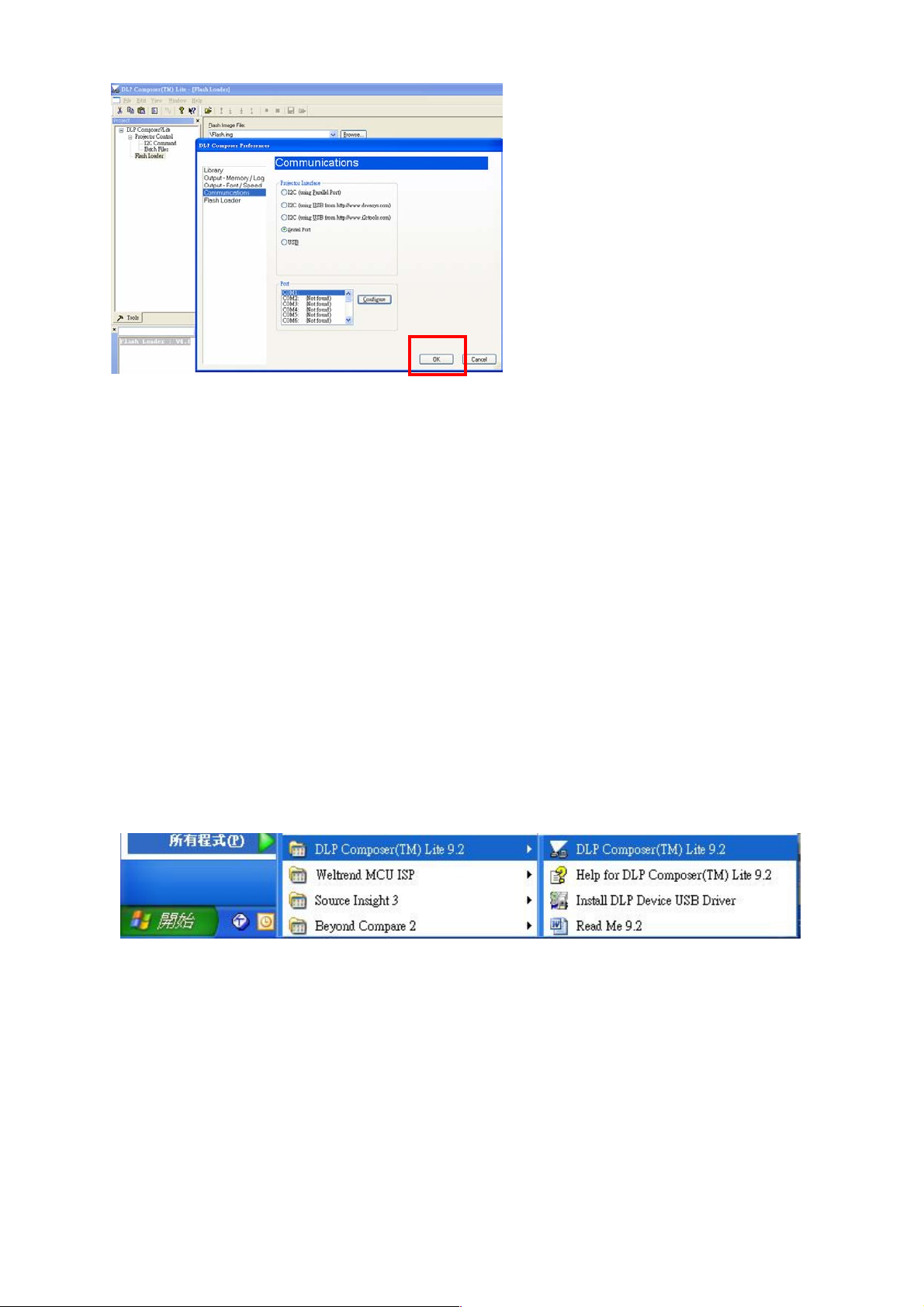
3. Execute DLP Composer Lite 9.2 program
4. To select the RS-232 communications interface, choose "Preferences" from the
"Edit" menu, click the "Communications" page and choose "Serial Port".

27
5. Click on “Flash Loader” and browse the image file (new version firmware)
6. Select Complete Image Download, and make sure to check “Skip Boot loader area
(32KB)”
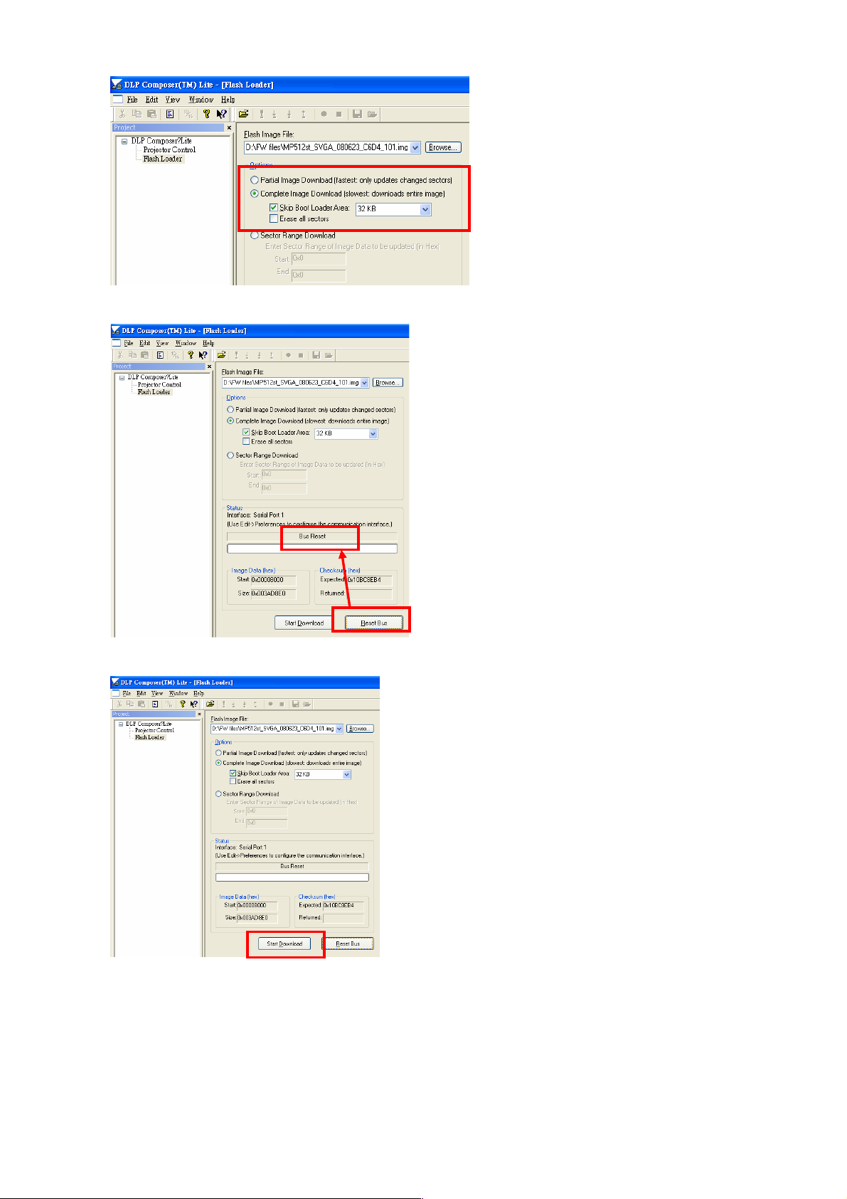
28
7. Press “Reset Bus” and check the status which should show “Bus Reset”
8. Press “Start Download” to begin update new firmware.
9. Press “Yes” to continue. (when download new firmware and power LED will show
purple.)
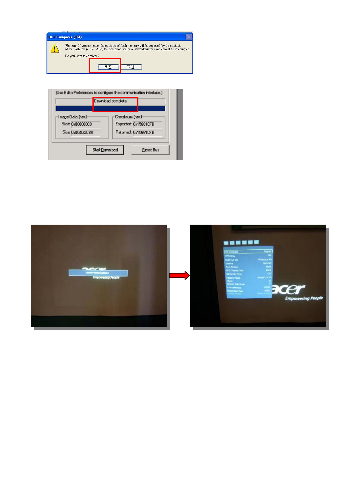
29
10. Wait till composer lite notice download complete.
When download complete, LED signal on projector will show standby status.
Method to enter factory menu
1. Press keypad Power and image will show Power Down OSD function
2. Press keypad Left twice then press Menu, then enter the Factory mode.
Step 1
Step 2
30
EDID Upgrade SOP
Equipment List
1. PC : with parallel (printer) port
2. EDID Board
3. Printer cable : 25pin male-female (connect PC to EDID board)
4. D-sub cable* : with full 15pin (connect EDID board to Projector)
5. HDMI cable*(connect EDID board to Projector)
6. DVI cable* (connect EDID board to Projector)
(*Note: Not every model’s EDID input (D-sub, DVI, HDMI) is the same. Need to check what
kind of file you need before download.)
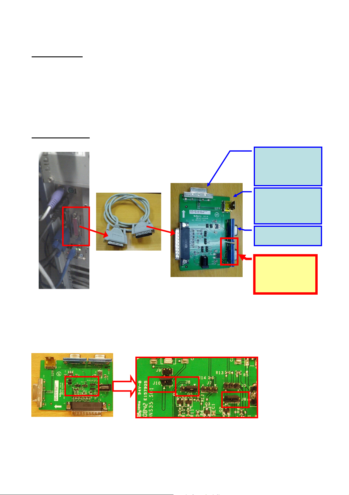
Setup Equipment
1. Connect between PC, EDID board and the Projector:
2. Need to set Jumper before using EDID board :
<Jumper setting :>
J6 : 1,2 short
J8 : 1,2 short
J10 : short
3. How to use Download Tool :
Link to Main
board :
For D-sub DDC
download
Link to Projector :
For HDMI DDC
download
(no need in
X1130/ X1230/ X1230S/
X1235/ X1230K series)
Link to Projector :
For
DVI-D DDC download
(no need in X1130/ X1230/
X1230S/ X1235/ X1230K
series)
“25pin male-female
cable” (normal
printer cable)
EDID board
PC with parallel
(printer) port
Please ignore this
connector
 Loading...