


SERVICE MANUAL
X1161/X1261/X1161A/X1161N/X110/H5360
Date |
Revise Version |
|
Description |
|
|
|
|
2009.05.22 |
V1.0 |
Initial Issue |
|
|
|
|
|
2009.06.25 |
V2.0 |
Modify Chapter 5 |
|
|
|
|
|
|
|
1. Add X1161’s extended models: X1161A, X1161N,X110 |
|
2009.08.06 |
V3.0 |
2. |
Update Engineering Spec. of Chapter 1 |
|
|
3. |
Modify Chapter 4 |
|
|
|
|
|
|
1. Add X1261’s extended models: H5360 |
|
2009.09.16 |
V4.0 |
2. |
Update Engineering Spec. of Chapter 1 |
|
|
3. |
Modify Chapter 4 |
|
|
|
|
Copyright September, 2009 |
All Rights Reserved P/N: 36.8CP01G001 |
||
SI : |
TSE: |
Check: |
Approved: |
Preface
This manual is applied to X1161/X1261/X1161A/X1161N/X110/H5360 projection system. The manual gives you a brief description of basic technical information to help in service and maintain the product.
Your customers will appreciate the quick response time when you immediately identify problems that occur with our products. We expect your customers will appreciate the service that you offer them.
This manual is for technicians and people who have an electronic background. Please send the product back to the distributor for repairing and do not attempt to do anything that is complex or is not mentioned in the troubleshooting.
Note: The information found in this manual is subject to change without prior notice. Any subsequent changes made to the data herein will be incorporated in future edition.
X1161/X1261/X1161A/X1161N/X110/H5360 Service Manual
Copyright September, 2009
All Rights Reserved
Manual Version 4.0
|
X1161/X1261/X1161A/X1161N/X110/H5360 |
Confidential |
i |
X1161/X1161A/X1161N/X110/X1261/H5360 Comparison List
Models |
H5360 |
X1261 |
X1161 |
X1161A |
X1161N |
X110 |
|
Parts |
|||||||
|
|
|
|
|
|
||
NAME LABEL |
35.8ER02H001 |
35.8CQ03H001 |
35.8CP02H001 |
35.8CP07H001 |
35.8CP05H001 |
35.8CP10H001 |
|
MAIN BOARD |
70.8ER17GR01 |
70.8CQ09GR01 |
70.8CP25GR01 |
70.8CP27GR01 |
70.8CP29GR01 |
70.8CP28GR01 |
|
DMD CHIP |
48.8ER01G001 |
48.8CQ01G003 |
|
48.8EH01G001 |
|
||
IO COVER |
70.8ER18GR01 |
70.8CQ08GR01 |
|
70.8CP23GR01 |
|
||
ENGINE |
70.8ER15GR01 |
70.8CQ07GR01 |
|
70.8CP22GR01 |
|
||
SPEAKER |
49.8CQ01G001 |
|
N/A |
|
|||
LAMP BLOWER |
|
49.8CS01G002 |
|
49.8CS01G001 |
|||
SYSTEM FAN |
|
49.8CP02G002 |
|
49.8CP02G001 |
|||
COLOR WHEEL |
70.8ER16GR01 |
|
|
70.8CP21GR01 |
|
|
|
LAMP |
SP.8ER01GC01 |
|
|
SP.8CP01GC01 |
|
|
|
LVPS |
75.8FE01GP01 |
|
|
75.8CP03GP01 |
|
|
|
LAMP DRIVER |
70.8ER20GR01 |
|
|
75.8BA01G002 |
|
|
|
BOTTOM COVER |
70.8ER19GR01 |
|
|
70.8CP26GR01 |
|
|
|
TOP COVER |
75.8ER01G001 |
|
|
75.8CP04H001 |
|
|
|
FRONT COVER |
51.8CP09H021 |
|
|
51.8CP09H001 |
|
|
|
|
X1161/X1261/X1161A/X1161N/X110/H5360 |
Confidential |
ii |
Table of Content
Chapter 1 Introduction |
|
Highlight |
1-1 |
Compatible Mode |
1-5 |
Product Overview |
1-9 |
Chapter 2 Disassembly Process & Assembly Process |
|
Equipment Needed & Product Overview |
2-1 |
Disassemble Lamp Cover Module |
2-2 |
Disassemble Lamp Module |
2-2 |
Disassemble Top Cover Module |
2-3 |
Disassemble Top Shielding |
2-3 |
Disassemble Front Cover and IR Sensor Board |
2-4 |
Disassemble Main Board Module and IO Cover Module |
2-5 |
Disassemble Engine Module |
2-7 |
Disassemble Color Wheel Module |
2-8 |
Disassemble DMD Chip and DMD Board |
2-8 |
Disassemble Zoom Ring |
2-9 |
Disassemble Focus Ring |
2-9 |
Disassemble System Fan Module |
2-10 |
Disassemble Blower |
2-11 |
Disassemble LVPS Module |
2-11 |
Disassemble Lamp Driver Module |
2-12 |
Disassemble Interrupt Switch |
2-13 |
Disassemble Bottom Shielding |
2-13 |
Disassemble Speaker (for X1261/H5360) |
2-14 |
Rod Adjustment |
2-14 |
Re-write System and Lamp Usage Hour |
2-15 |
Assemble Speaker (for X1261/H5360) |
2-16 |
|
X1161/X1261/X1161A/X1161N/X110/H5360 |
Confidential |
iii |
Assemble Bottom Shielding |
2-17 |
Assemble Interrupt Switch |
2-17 |
Assemble Lamp Driver Module |
2-18 |
Assemble LVPS Module |
2-19 |
Assemble Blower |
2-19 |
Assemble System Fan Module |
2-20 |
Assemble Focus Ring |
2-21 |
Assemble Zoom Ring |
2-21 |
Assemble DMD Chip and DMD Board |
2-22 |
Assemble Color Wheel Module |
2-22 |
Assemble Engine Module |
2-23 |
Assemble IO Cover and Main Board Module |
2-23 |
Assemble IR Sensor Board and Front Cover |
2-25 |
Assemble Top Shielding |
2-26 |
Assemble Top Cover Module |
2-26 |
Assemble Lamp Module |
2-27 |
Assemble Lamp Cover Module |
2-27 |
Chapter 3 Troubleshooting |
|
LED Lighting Message |
3-1 |
Main Procedure |
3-2 |
Chapter 4 Function Test & Alignment Procedure |
|
Test Equipment Needed |
4-1 |
Service Mode |
4-1 |
OSD Reset |
4-1 |
Test Condition |
4-2 |
Test Inspection Procedure |
4-3 |
PC Mode |
4-4 |
|
X1161/X1261/X1161A/X1161N/X110/H5360 |
Confidential |
iv |
|
Calibration |
4-7 |
|
Video Performance |
4-9 |
|
Optical Performance Measure |
4-10 |
|
Others |
4-12 |
Chapter 5 |
Firmware Upgrade |
|
|
Equipment Needed |
5-1 |
|
DLP Composer Lite Setup Procedure |
5-2 |
|
USB Driver Upgrade Procedure (for X1161 only) |
5-4 |
|
Firmware Upgrade Procedure |
5-5 |
|
Waveform Download |
5-8 |
Chapter 6 |
EDID Upgrade |
|
|
EDID Introduction |
6-1 |
|
Equipment Needed |
6-2 |
|
Setup Procedure (VGA) |
6-3 |
|
EDID Key-In Procedure |
6-4 |
|
Un-lock SNID and Default Language Reset |
6-6 |
Appendix A |
|
|
|
Exploded Overview |
I |
Appendix B |
|
|
|
Serial Number System Definition |
I |
|
PCBA Code Definition |
II |
Appendix C
RS232 function command summary table (for X1261/H5360) I
|
X1161/X1261/X1161A/X1161N/X110/H5360 |
Confidential |
v |
Chapter 1
Introduction
1-1 Highlight
No |
Item |
Description |
|
1 |
Dimensions (W x H x D) |
● 268 mm x 192 mm x 80 mm |
|
|
|
|
|
2 |
Weight |
● <4.9 lbs |
|
3 |
Tilt Angle |
● 2.7 degree with elevator mechanism |
|
|
|
● Universal AC 100 – 240 V ~ 50-60 Hz with PFC input |
|
4 |
Power Supply |
● Variance FAN speed control (Depends on temperature |
|
|
|
variant) |
|
5 |
Keystone correction |
● +/ -40 degree (80 degree) |
|
|
|
● Advanced Air Flow |
|
|
|
● Two fans with system |
|
6 |
Cooling system |
● Temperature control circuits with adaptive fan rotational |
|
|
|
speeds |
|
|
|
● Maximum touch temperature follow UL60950-1 |
|
|
|
● Engineering spec: |
|
|
|
• 2250 ANSI Lumens (Typical) |
|
7 |
Brightness |
• 2000 ANSI Lumens (Minimum) |
|
● Marketing spec: |
|||
|
|
||
|
|
• 2500 ANSI Lumens (Standard) |
|
|
|
• 2000 ANSI Lumens (ECO) |
|
X1161/X1261/X1161A/X1161N/X110/H5360 |
Confidential |
1- |

No |
Item |
|
Description |
|
||
|
|
|
● Engineering spec: |
|
||
|
|
|
For X1161/X1161N/X1161A/X110: |
|
||
|
|
|
• 2500: 1 Full White with full power / full Black with eco |
|
||
|
|
|
power (Minimum; projection lens at tele mode) |
|
||
|
|
|
• 3600: 1 Full White with full power / full Black with eco |
|
||
|
|
|
power (Typical; projection lens at tele mode) |
|
||
|
|
|
For X1261: |
|
||
|
|
|
• 2100: 1 Full White with full power / full Black with eco |
|
||
|
|
|
power (Minimum; projection lens at tele mode) |
|
||
8 |
Contrast |
|
• 3300: 1 Full White with full power / full Black with eco |
|
||
|
power (Typical; projection lens at tele mode) |
|
||||
|
|
|
|
|||
|
|
|
For H5360: |
|
||
|
|
|
• 2320: 1 Full White with full power / full Black with eco |
|
||
|
|
|
power (Minimum; projection lens at tele mode) |
|
||
|
|
|
• 2900: 1 Full White with full power / full Black with eco |
|
||
|
|
|
power (Typical; projection lens at tele mode) |
|
||
|
|
|
● Marketing spec: |
|
||
|
|
|
• 3500: 1 (for X1161/X1161N/X1161A/X110) |
|
||
|
|
|
• 3000: 1 (for X1261) |
|
||
|
|
|
• 3200: 1 (for H5360) |
|
||
|
|
|
● Engineering spec: |
|
||
|
|
|
• 65% JBMA (Minimum; Full power mode) |
|
||
9 |
Uniformity |
|
• 80% JBMA (Typical; Full power mode) |
|
||
|
|
|
● Marketing spec: |
|
||
|
|
|
• 85% |
|
||
|
|
|
● 1.95 – 2.15 distance/width @60” (for X1161/X1261/ |
|
||
10 |
Throw ratio |
|
X1161N/X1161A/X110) |
|
||
|
|
|
● 1.55 – 1.7 distance/width @60” (for H5360) |
|
||
11 |
Audio |
|
● 2W*1 (for X1261 /H5360 only) |
|
||
|
|
|
● F# 2.41~2.55, f = 21.79~23.99 mm, 1.10X Mechanical Zoom |
|||
12 |
Projection lens |
|
Lens (for X1161/X1261/X1161N/X1161A/X110) |
|
||
|
● F# 2.5~2.6, f = 21.86~24 mm, 1.10X Mechanical Zoom Lens |
|||||
|
|
|
||||
|
|
|
(for H5360) |
|
||
13 |
Lamp life |
|
● 3000 hours, 50% survival rate (Full power Mode) |
|
||
|
● 4000 hours, 50% survival rate (Eco power Mode) |
|
||||
|
|
|
|
|||
14 |
System controller |
|
● TI DDP2430 (for X1161/X1261/X1161N/X1161A/X110) |
|
||
|
● TI DDP2431 (for H5360) |
|
||||
|
|
|
|
|||
|
|
|
● Lamp Assembly could be changed by customer himself, but |
|||
15 |
Lamp housing |
|
should read the user manual for instruction in advance |
|
||
|
● Lamp Assembly should be provided by Coretronic and |
|
||||
|
|
|
|
|||
|
|
|
distributed through authorized agencies |
|
||
|
|
|
|
|
|
|
|
|
X1161/X1261/X1161A/X1161N/X110/H5360 |
Confidential |
|
1- |
|

No |
Item |
Description |
|
|
|
● TI DMD 0.55” 12° 2xLVDS S450 SVGA Digital Mirror Device |
|
|
|
(for X1161/X1161N/X1161A/X110) |
|
16 |
TI DMD |
● TI DMD 0.55” 12° 2xLVDS S450 XGA Digital Mirror Device |
|
(for X1261) |
|||
|
|
||
|
|
● TI DMD 0.62” 12° S450 720p Digital Mirror Device (for |
|
|
|
H5360) |
|
|
|
● 800(H) x 600(V) (for X1161/X1161N/X1161A/X110)) |
|
17 |
Number of active dots |
● 1024(H) x 768(V) (for X1261) |
|
|
|
● 1280(H) x 720(V) (for H5360) |
|
|
|
● 6 segments (R81Y41G84C31W52B71) (for X1161/X1261/ |
|
18 |
Color wheel |
X1161N/X1161A/X110) |
|
● 6 segments (R90Y35G85C33W42B75) (for H5360) |
|||
|
|
||
|
|
● 6000 ~ 7650 rpm @ CW 2X and 1.5X (50 ~85Hz) |
|
|
|
● 180Watt OSRAM E20.8 open type Lamp (for X1161/X1261/ |
|
19 |
Lamp |
X1161N/X1161A/X110) |
|
|
|
● 200Watt OSRAM E20.8 open type Lamp (for H5360) |
|
|
|
● Standards : |
|
20 |
Video compatibility |
• NTSC (3.58/4.43) |
|
• PAL (B/D/G/H/I/M/N) |
|||
|
|
• SECAM (B/D/G/K/K1/L) |
|
|
|
• HDTV (480i,576i 480p, 576p, 720p, 1080i, 1080p) |
|
X1161/X1261/X1161A/X1161N/X110/H5360 |
Confidential |
1- |

No |
Item |
Description |
|
|
|
● For X1161/1161A/X110: |
|
|
|
• VGA In * 1: One D-Sub 15-Pin Female Connector for PC |
|
|
|
input and analog Data ( Component i/p, HDTV, RGB Sync) |
|
|
|
• S-video * 1: One Mini DIN 4-Pin connector for S-Video |
|
|
|
Input Connector |
|
|
|
• Composite * 1: One RCA Jack for Composite Video Input |
|
|
|
Connector |
|
|
|
• USB * 1: One Type-B USB support F/W up-grade and |
|
|
|
reserve remote Page-Up and Page-Down function |
|
|
|
● For X1161N: |
|
|
|
• VGA In * 1: One D-Sub 15-Pin Female Connector for PC |
|
|
|
input and analog Data ( Component i/p, HDTV, RGB Sync) |
|
|
|
• USB * 1: One Type-B USB support F/W up-grade and re- |
|
|
|
serve remote Page-Up and Page-Down function |
|
|
|
● For X1261: |
|
|
|
• VGA In * 1: One D-Sub 15-Pin Female Connector for PC |
|
|
|
input and analog Data ( Component i/p, HDTV, RGB Sync) |
|
21 |
Terminal |
• S-video * 1: One Mini DIN 4-Pin connector for S-Video |
|
Input Connector |
|||
|
|
||
|
|
• Composite * 1: One RCA Jack for Composite Video Input |
|
|
|
Connector |
|
|
|
• VGA out * 1: One D-Sub 15-Pin Female Connector for VGA |
|
|
|
output ( Component i/p, HDTV, RGB Sync) |
|
|
|
• Audio in * 1: One 3.5mm phone jack for Audio input |
|
|
|
• RS232 * 1: One Mini DIN 3-Pin connector for RS232 |
|
|
|
● For H5360 |
|
|
|
• VGA In * 1: One D-Sub 15-Pin Female Connector for PC |
|
|
|
input and analog Data ( Component i/p, HDTV, RGB Sync) |
|
|
|
• S-video * 1:One Mini DIN 4-Pin connector for S-Video |
|
|
|
Input |
|
|
|
• Composite * 1: One RCA jack for Composite Video Input |
|
|
|
• Component * 1: Three RCA jacks for Component Input |
|
|
|
• HDMI * 1: Support HDMI v1.3 |
|
|
|
• Audio in * 1: One 3.5mm phone jack for Audio input |
|
|
|
• RS232 * 1: One Mini DIN 3-Pin connector for RS232 |
|
X1161/X1261/X1161A/X1161N/X110/H5360 |
Confidential |
1- |
No |
Item |
Description |
|
|
● Hsync Frequency 30~ 100 kHz |
|
|
● Vsync Frequency 50~ 85 Hz |
|
|
● Video Signal RGB (PC) |
|
|
• Analog RGB 0.7Vp-p, 75 ohm, Separate TTL H,V Sync |
22 |
Input signal spec. |
• Analog RGB 1Vp-p, 75 ohm, Sync. On Green signal |
• Analog RGB 0.7Vp-p, 75 ohm, Composite TTL Sync. |
●Video
•Composite video 1Vp-p,75 ohm
•S-video Luminance 0.714Vp-p, 75 ohm
•Chrominance 0.286Vp-p, 75 ohm
•Component Video 1Vp-p, 75 ohm
●Operating:
•for 0 - 2500 ft, 5 - 35 °C
23 |
Temperature |
• for 2500 |
- 5000 ft, 5 - 30 °C |
|
|
|
• for 5000 |
- 10000 ft, 5 - 25 °C |
|
|
|
● Storage: -20°C ~ 60°C |
||
24 |
Maximum Humidity |
● Operating: 5°C ~ 35°C, 80%RH (Max.), Non-condensing |
||
● Storage: -20°C ~ 60°C, 80%RH (Max.), Non-condensing |
||||
|
|
|||
1-2 Compatible Mode
Compatibility modes (VGA Analog) (for X1161/X1261/X1161N/X1161A/X110)
Compatibility |
|
Resolution |
V.Frequency [Hz] |
H.Frequency [KHz] |
|
(1) VGA Analog - PC Signal |
|
|
|
||
|
|
640 x 480 |
60 |
31.5 |
|
|
|
640 x 480 |
72 |
37.9 |
|
VGA |
|
640 x 480 |
75 |
37.5 |
|
|
640 x 480 |
85 |
43.3 |
|
|
|
|
|
|||
|
|
720 x 400 |
70 |
31.5 |
|
|
|
720 x 400 |
85 |
37.9 |
|
|
|
800 x 600 |
56 |
35.1 |
|
|
|
800 x 600 |
60 |
37.9 |
|
SVGA |
|
800 x 600 |
72 |
48.1 |
|
|
|
800 x 600 |
75 |
46.9 |
|
|
|
800 x 600 |
85 |
53.7 |
|
|
|
|
|
|
|
|
|
X1161/X1261/X1161A/X1161N/X110/H5360 |
Confidential |
1- |
|

Compatibility |
|
Resolution |
V.Frequency [Hz] |
|
H.Frequency [KHz] |
||
|
|
1024 x 768 |
60 |
|
48.4 |
|
|
XGA |
|
1024 x 768 |
70 |
|
56.5 |
|
|
|
1024 x 768 |
75 |
|
60.0 |
|
|
|
|
|
|
|
|
|||
|
|
1024 x 768 |
85 |
|
68.7 |
|
|
|
|
1152 x 864 |
70 |
|
63.8 |
|
|
|
|
1152 x 864 |
75 |
|
67.5 |
|
|
|
|
1152 x 864 |
85 |
|
77.1 |
|
|
SXGA |
|
1280 x 1024 |
60 |
|
64.0 |
|
|
|
|
1280 x 1024 |
72 |
|
77.0 |
|
|
|
|
1280 x 1024 |
75 |
|
80.0 |
|
|
|
|
1280 x 1024 |
85 |
|
91.1 |
|
|
QuadVGA |
|
1280 x 960 |
60 |
|
60.0 |
|
|
|
1280 x 960 |
75 |
|
75.2 |
|
|
|
|
|
|
|
|
|||
SXGA+ |
|
1400 x 1050 |
60 |
|
65.3 |
|
|
UXGA |
|
1600 x 1200 |
60 |
|
75.00 |
|
|
|
|
640 x 480 |
66.6(67) |
|
34.9 |
|
|
|
|
800 x 600 |
60 |
|
37.9 |
|
|
Power Mac G4 |
|
1024 x 768 |
60 |
|
48.4 |
|
|
|
|
1152 x 870 |
75 |
|
68.7 |
|
|
|
|
1280 x 960 |
75 |
|
75.0 |
|
|
|
|
640 x 480 |
60 |
|
31.4 |
|
|
|
|
640 x 480 |
66.6(67) |
|
34.9 |
|
|
PowerBook G4 |
|
800 x 600 |
60 |
|
37.9 |
|
|
|
1024 x 768 |
60 |
|
48.4 |
|
|
|
|
|
|
|
|
|||
|
|
1152 x 870 |
75 |
|
68.7 |
|
|
|
|
1280 x 960 |
75 |
|
75.0 |
|
|
i Mac DV(G3) |
|
1024 x 768 |
75 |
|
60.0 |
|
|
(2) VGA Analog - Extended Wide timing |
|
|
|
|
|
||
|
|
1280 x 768 |
60 |
|
47.8 |
|
|
|
|
1280 x 768 |
75 |
|
60.3 |
|
|
WXGA |
|
1280 x 768 |
85 |
|
68.6 |
|
|
|
1280 x 720 |
60 |
|
44.8 |
|
|
|
|
|
|
|
|
|||
|
|
1280 x 800 |
60 |
|
49.6 |
|
|
|
|
1440 x 900 |
60 |
|
59.9 |
|
|
WSXGA+ |
|
1680 x 1050 |
60 |
|
65.3 |
|
|
Horizontal scan rate |
30k-100kHz |
|
|||||
Vertical scan rate |
50-85Hz |
|
|||||
Max. pixel rate |
170MHz |
|
|||||
|
|
|
|
|
|
|
|
|
|
X1161/X1261/X1161A/X1161N/X110/H5360 |
Confidential |
|
1- |
||

Compatibility modes (VGA Analog) (for H5360)
Compatibility |
|
Resolution |
V.Frequency [Hz] |
H.Frequency [KHz] |
||
(1) VGA Analog - PC Signal |
|
|
|
|
||
|
|
640 x 480 |
60 |
31.5 |
|
|
|
|
640 x 480 |
72 |
37.9 |
|
|
VGA |
|
640 x 480 |
75 |
37.5 |
|
|
|
|
640 x 480 |
85 |
43.3 |
|
|
|
|
640 x 480 |
120 |
61.6 |
|
|
|
|
800 x 600 |
56 |
35.2 |
|
|
|
|
800 x 600 |
60 |
37.9 |
|
|
SVGA |
|
800 x 600 |
72 |
48.1 |
|
|
|
800 x 600 |
75 |
46.9 |
|
||
|
|
|
||||
|
|
800 x 600 |
85 |
53.7 |
|
|
|
|
800 x 600 |
120 |
77.2 |
|
|
|
|
1024 x 768 |
60 |
48.4 |
|
|
|
|
1024 x 768 |
70 |
56.5 |
|
|
XGA |
|
1024 x 768 |
75 |
60.0 |
|
|
|
|
1024 x 768 |
85 |
68.7 |
|
|
|
|
1024 x 768 |
120 |
98.8 |
|
|
|
|
1152 x 864 |
70 |
63.8 |
|
|
|
|
1152 x 864 |
75 |
67.5 |
|
|
|
|
1152 x 864 |
85 |
77.1 |
|
|
SXGA |
|
1280 x 1024 |
60 |
64.0 |
|
|
|
|
1280 x 1024 |
72 |
77.9 |
|
|
|
|
1280 x 1024 |
75 |
80.0 |
|
|
|
|
1280 x 1024 |
85 |
91.1 |
|
|
QuadVGA |
|
1280 x 960 |
60 |
60.0 |
|
|
|
1280 x 960 |
75 |
75.0 |
|
||
|
|
|
||||
SXGA+ |
|
1400 x 1050 |
60 |
65.3 |
|
|
UXGA |
|
1600 x 1200 |
60 |
75.00 |
|
|
|
|
640 x 480 |
60 |
31.5 |
|
|
|
|
640 x 480 |
66.6(67) |
35 |
|
|
PowerBook G4 |
|
800 x 600 |
60 |
37.88 |
|
|
|
1024 x 768 |
60 |
48.4 |
|
||
|
|
|
||||
|
|
1152 x 870 |
75 |
68.7 |
|
|
|
|
1280 x 960 |
75 |
75.2 |
|
|
i Mac DV(G3) |
|
1024 x 768 |
75 |
60.0 |
|
|
|
|
|
|
|
|
|
|
|
X1161/X1261/X1161A/X1161N/X110/H5360 |
Confidential |
|
1- |
|

Compatibility |
Resolution |
V.Frequency [Hz] |
H.Frequency [KHz] |
|
(2) VGA Analog - Extended Wide timing |
|
|
||
|
1280 x 768 |
60 |
47.8 |
|
|
1280 x 768 |
75 |
60.3 |
|
WXGA |
1280 x 768 |
85 |
68.6 |
|
1280 x 720 |
60 |
44.8 |
||
|
||||
|
1280 x 800 |
60 |
49.6 |
|
|
1366 x 768 |
60 |
47.71 |
|
WXGA+ |
1440 x 900 |
60 |
55.9 |
|
WSXGA+ |
1440 x 900 |
60 |
65.3 |
|
Horizontal scan rate |
30k-100kHz |
|||
Vertical scan rate |
50-85Hz |
|||
Max. pixel rate |
170MHz |
|||
Note: If the Compatibility modes supportive signal is different from User's Manual, please refer to User’s Manual.
|
X1161/X1261/X1161A/X1161N/X110/H5360 |
Confidential |
1- |

1-3 Product Overview
Projector Outlook
Front /Upper side
Item |
Description |
Item |
Description |
1 |
Ventilation (inlet) |
6 |
Lens cap |
2 |
Ventilation (outlet) |
7 |
Power button |
3 |
Remote control receivers |
8 |
Remote control |
4 |
Focus ring |
9 |
Zoom lever |
5 |
Zoom lens |
10 |
Horn |
|
X1161/X1261/X1161A/X1161N/X110/H5360 |
Confidential |
1- |

Rear side (for X1161/X1261/X1161A/X1161N/X110)
Item |
Description |
Item |
Description |
1 |
Power socket |
Below items are for X1261 only: |
|
2 |
KensingtonTM lock port |
4 |
S-Video input connector |
|
|
|
|
3 |
PC analog signal/HDTV/component video |
5 |
Composite video input connector |
input connector (VGA IN 1 or VGA IN) |
|||
Below items are for X1161/X1161A/X110 |
6* |
PC analog signal/HDTV/component |
|
only: |
video input connector (VGA IN 2) |
||
4 |
S-Video input connector |
7 |
RS232 connector |
5 |
Composite video input connector |
8 |
Monitor loop-through output |
connector (VGA-Out) |
|||
10 |
USB connector |
9 |
Audio input connector |
7* |
RS232 connector |
10* |
USB connector |
Below item is for X1161N: |
|
|
|
10 |
USB connector |
|
|
Note: “*” for optional connector port.
|
X1161/X1261/X1161A/X1161N/X110/H5360 |
Confidential |
1-10 |

Rear side (for H5360)
Item |
Description |
Item |
Description |
1 |
Power socket |
6 |
YPbPr input connector |
|
|
|
|
2 |
KensingtonTM lock port |
7 |
S-Video input connector |
|
|
|
|
3 |
RS232 connector |
8 |
Composite video input connector |
4 |
PC analog signal/HDTV/component video |
9 |
Audio input connector |
input connector (VGA IN 1 or VGA IN) |
|||
5 |
HDMI connector |
|
|
|
|
|
|
|
X1161/X1261/X1161A/X1161N/X110/H5360 |
Confidential |
1-11 |

Remote Control and Control Panel Layout
|
X1161/X1261/X1161A/X1161N/X110/H5360 |
Confidential |
1-12 |
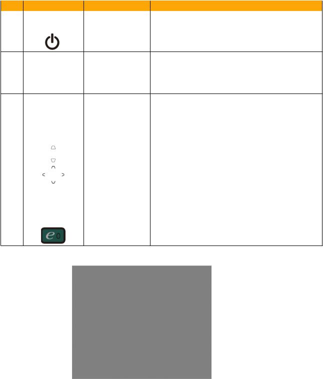
Item |
Icon |
Function |
Description |
1 |
|
Remote control |
Receives signals from remote control. |
|
receiver |
||
|
|
|
|
2 |
|
POWER |
Refer to the “Turning the Projector On/Off” section. |
• Press “MENU” to launch the Onscreen display
3 MENU (OSD) menu, back to the previous step for the OSD menu operation or exit the OSD menu.
• Confirm your selection of items.
4KeyPad 0~9 Press “0~9” to input a password in the “Security”.
5 |
KeyPad 0~9 |
To choose the desired aspect ratio (Auto/4:3/16:9). |
|
6 |
RESYNC |
Automatically synchronizes the projector to the |
|
input source. |
|||
|
|
||
7 |
FREEZE |
To pause the screen image. |
|
8 |
KEYSTONE |
Adjusts the image to compensate for distortion |
|
caused by tilting the projector (± 40 degrees). |
|||
|
|
||
9 |
Four directional |
Use up, down, left, right buttons to select items or |
|
select keys |
make adjustments to your selection. |
||
|
|||
10 |
ZOOM |
Zooms the projector display in or out. |
|
11 |
SOURCE |
Changes the active source. |
|
12 |
HIDE |
Momentarily turns off the video. Press “HIDE” to |
|
hide the image, press again to display the image. |
|||
|
|
||
13 |
Empowering |
Unique Acer functions: eView, eTimer, ePower |
|
key |
Management. |
||
|
Note:
|
X1161/X1261/X1161A/X1161N/X110/H5360 |
Confidential |
1-13 |
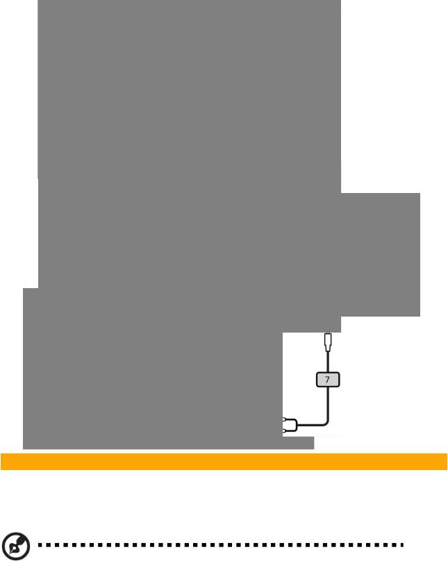
Getting Started
Connecting the Projector
Item |
Description |
Item |
Description |
|
|
|
|
1 |
Power cord |
6 |
S-Video cable |
2 |
VGA cable |
7 |
Audio cable jack/jack |
3 |
Composite video cable |
8 |
Audio cable jack/RCA |
4 |
RS232 cable |
9 |
USB cable |
Note: To ensure the projector works well with your computer, please make sure the timing of the display mode is compatible with the projector.
|
X1161/X1261/X1161A/X1161N/X110/H5360 |
Confidential |
1-14 |
System Block Diagram (for X1161/X1161A/X110)
|
X1161/X1261/X1161A/X1161N/X110/H5360 |
Confidential |
1-15 |

System Block Diagram (for X1261)
|
X1161/X1261/X1161A/X1161N/X110/H5360 |
Confidential |
1-16 |

System Block Diagram (for H5360)
|
X1161/X1261/X1161A/X1161N/X110/H5360 |
Confidential |
1-17 |

Bottom Cover Dimension
|
X1161/X1261/X1161A/X1161N/X110/H5360 |
Confidential |
1-18 |

Chapter 2
Disassembly & Assembly Process
2-1 Equipment Needed & Product Overview
1.Screw Bit (+): 105
2.Screw Bit (+): 107
3.Screw Bit (-): 107
4.Hex Sleeves 5mm
5.Long Nose Nipper
6.Tweezers
7.Projector
*Before you start: This process is protective level II. Operators should wear electrostatic chains.
*Note: - If you need to replace the Main Board, you have to get into Service Mode and record the lamp usage hour, please refer to section 2-21.
-As the process of X1161/ X1161A/X1161N/X110/H5360 disassembling is the same as X1261, we take X1261 for example here.
|
X1161/X1261/X1161A/X1161N/X110/H5360 |
Confidential |
2- |
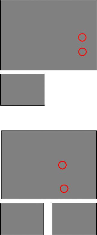
2-2 Disassemble Lamp
Cover Module
1.Loosen 2 screws (as red circle) on the Lamp Cover.
2.Disassemble the Lamp Cover Module.
2-3 Disassemble Lamp
Module
1.Loosen 2 screws (as red circle) on the Lamp Module.
2.Take off the Lamp Module.
|
X1161/X1261/X1161A/X1161N/X110/H5360 |
Confidential |
2- |
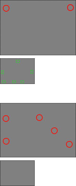
2-4 Disassemble Top Cover
Module
1.Unscrew 2 screws (as red circle) from the Bottom Cover.
2.Remove the Top Cover Module.
Note: - When you remove the Top Cover, take care the 6 tenons (as green square).
2-5 Disassemble Top
Shielding
1.Unscrew 5 screws (as red circle) to disassemble the Top Shielding.
|
X1161/X1261/X1161A/X1161N/X110/H5360 |
Confidential |
2- |
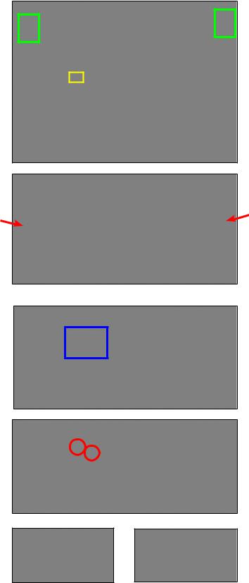
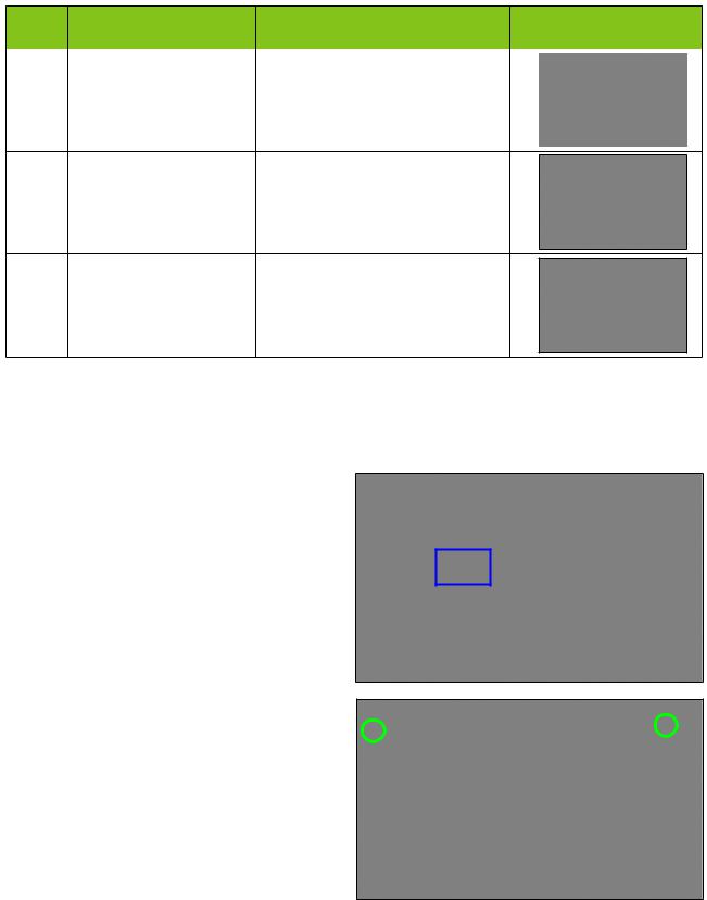
2-6 Disassemble Front
Cover and IR Sensor
Board
1. Unplug 1 connector (as yellow square).
2.Press two sides (as red arrows point) to unfasten 2 tenons (as green square).
3.Remove the Front Cover.
4.Tear off the mylar (as blue square).
5.Unscrew 2 screws (as red circle).
6.Remove the IR Sensor Board and IR Cap.
IR Sensor Board IR Cap
|
X1161/X1261/X1161A/X1161N/X110/H5360 |
Confidential |
2- |
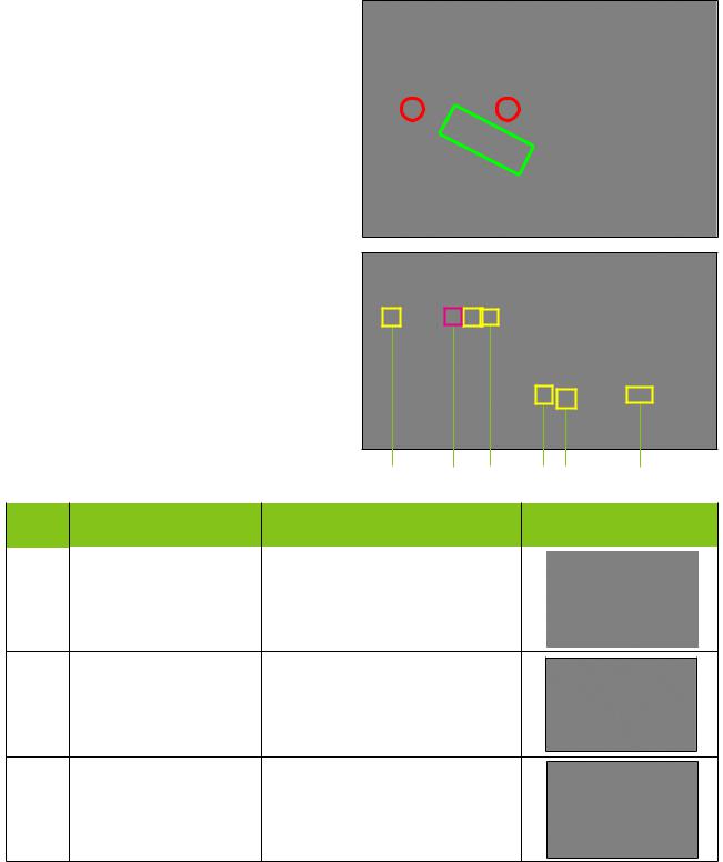
2-7 Disassemble Main Board
Module and IO Cover
Module
1.Tear off 3M tape (as green square).
2.Unplug 6 connectors (as yellow square).
3.Unscrew 2 screws (as red circle).
Please refer to the table as below for details of each connector.
|
|
F |
E |
D |
C B |
A |
|
|
|
|
|
|
|
Item |
Male Connector |
The key feature |
|
|
Figure |
|
on Main Board |
|
|
||||
|
|
|
|
|
|
|
A |
Lamp Driver |
Black wire tube (5 pin) |
|
|
|
|
B |
System Fan |
Compose of Red/Yellow/Black |
|
Wire (3 pin) |
|||
|
|
C |
Blower |
Compose of Red/Black/White |
|
Wire (3 pin) |
|||
|
|
|
X1161/X1261/X1161A/X1161N/X110/H5360 |
Confidential |
2- |
Item |
Male Connector |
The key feature |
Figure |
||
on Main Board |
|||||
|
|
|
|
||
D |
Photo Sensor |
Compose of Red/Black/White |
|
|
|
|
|
||||
Wire and Black wire tube (3 pin) |
|
|
|||
|
|
|
|
||
|
|
|
|
|
|
E |
IR |
Compose of Red/Black/Whit |
|
Wire and Black wire tube (3 pin) |
|||
|
|
F |
Speaker |
Compose of Red/Black Wire and |
|
(for X1261/H5360) |
Black wire tube (2 pin) |
||
|
4.Unplug 1 connector (as blue square).
5.Disassemble the Main Board Moudle.
6.Unscrew 2 screws (as green circle).
|
X1161/X1261/X1161A/X1161N/X110/H5360 |
Confidential |
2- |
 Loading...