


Travelmate 290
Table of contents
 Loading...
Acer TravelMate 290 Series
Service Guide
Service guide files and updates are available
on the ACER/CSD web; for more information,
please refer to http://csd.acer.com.tw
PART NO.: VD.T26V5.001
PRINTED IN TAIWAN
Download Free Service Manual at http://printer1.blogspot.com

Revision History
Please refer to the table below for the updates made on TravelMate 430 service guide.
Date Chapter Updates
II
Download Free Service Manual at http://printer1.blogspot.com

Copyright
Copyright © 2003 by Acer Incorporated. All rights reserved. No part of this publication may be reproduced,
transmitted, transcribed, stored in a retrieval system, or translated into any language or computer language, in
any form or by any means, electronic, mechanical, magnetic, optical, chemical, manual or otherwise, without
the prior written permission of Acer Incorporated.
Disclaimer
The information in this guide is subject to change without notice.
Acer Incorporated makes no representations or warranties, either expressed or implied, with respect to the
contents hereof and specifically disclaims any warranties of merchantability or fitness for any particular
purpose. Any Acer Incorporated software described in this manual is sold or licensed "as is". Should the
programs prove defective following their purchase, the buyer (and not Acer Incorporated, its distributor, or its
dealer) assumes the entire cost of all necessary servicing, repair, and any incidental or consequential
damages resulting from any defect in the software.
Acer is a registered trademark of Acer Corporation.
Intel is a registered trademark of Intel Corporation.
Pentium and Pentium II/III are trademarks of Intel Corporation.
Other brand and product names are trademarks and/or registered trademarks of their respective holders.
Download Free Service Manual at http://printer1.blogspot.com
III
Conventions
The following conventions are used in this manual:
SCREEN MESSAGES Denotes actual messages that appear
on screen.
NOTE Gives bits and pieces of additional
information related to the current
topic.
WARNING Alerts you to any damage that might
result from doing or not doing specific
actions.
CAUTION Gives precautionary measures to
avoid possible hardware or software
problems.
IMPORTANT Reminds you to do specific actions
relevant to the accomplishment of
procedures.
IV
Download Free Service Manual at http://printer1.blogspot.com

Preface
Before using this information and the product it supports, please read the following general information.
1. This Service Guide provides you with all technical information relating to the BASIC CONFIGURATION
decided for Acer's "global" product offering. To better fit local market requirements and enhance product
competitiveness, your regional office MAY have decided to extend the functionality of a machine (e.g.
add-on card, modem, or extra memory capability). These LOCALIZED FEATURES will NOT be covered
in this generic service guide. In such cases, please contact your regional offices or the responsible
personnel/channel to provide you with further technical details.
2. Please note WHEN ORDERING FRU PARTS, that you should check the most up-to-date information
available on your regional web or channel. If, for whatever reason, a part number change is made, it will
not be noted in the printed Service Guide. For ACER-AUTHORIZED SERVICE PROVIDERS, your Acer
office may have a DIFFERENT part number code to those given in the FRU list of this printed Service
Guide. You MUST use the list provided by your regional Acer office to order FRU parts for repair and
service of customer machines.
Download Free Service Manual at http://printer1.blogspot.com
V

VI
Download Free Service Manual at http://printer1.blogspot.com

Table of Contents
Chapter 1 System Specifications 1
Features . . . . . . . . . . . . . . . . . . . . . . . . . . . . . . . . . . . . . . . . . . . . . . . . . . . . . . . .1
System Block Diagram . . . . . . . . . . . . . . . . . . . . . . . . . . . . . . . . . . . . . . . . . . . . .3
Board Layout . . . . . . . . . . . . . . . . . . . . . . . . . . . . . . . . . . . . . . . . . . . . . . . . . . . . 4
Top View . . . . . . . . . . . . . . . . . . . . . . . . . . . . . . . . . . . . . . . . . . . . . . . . . . . . 4
Bottom View . . . . . . . . . . . . . . . . . . . . . . . . . . . . . . . . . . . . . . . . . . . . . . . . .5
Outlook View . . . . . . . . . . . . . . . . . . . . . . . . . . . . . . . . . . . . . . . . . . . . . . . . . . . . .6
Front Open View . . . . . . . . . . . . . . . . . . . . . . . . . . . . . . . . . . . . . . . . . . . . . . 6
Front View . . . . . . . . . . . . . . . . . . . . . . . . . . . . . . . . . . . . . . . . . . . . . . . . . . .7
Left Panel . . . . . . . . . . . . . . . . . . . . . . . . . . . . . . . . . . . . . . . . . . . . . . . . . . .8
Right Panel . . . . . . . . . . . . . . . . . . . . . . . . . . . . . . . . . . . . . . . . . . . . . . . . . .9
Rear Panel . . . . . . . . . . . . . . . . . . . . . . . . . . . . . . . . . . . . . . . . . . . . . . . . .10
Bottom Panel . . . . . . . . . . . . . . . . . . . . . . . . . . . . . . . . . . . . . . . . . . . . . . .11
Indicators . . . . . . . . . . . . . . . . . . . . . . . . . . . . . . . . . . . . . . . . . . . . . . . . . . . . . . 12
Lock Keys . . . . . . . . . . . . . . . . . . . . . . . . . . . . . . . . . . . . . . . . . . . . . . . . . . . . . . 13
Embedded Numeric Keypad . . . . . . . . . . . . . . . . . . . . . . . . . . . . . . . . . . . . . . . . 14
Windows Keys . . . . . . . . . . . . . . . . . . . . . . . . . . . . . . . . . . . . . . . . . . . . . . . . . . 15
Hot Keys . . . . . . . . . . . . . . . . . . . . . . . . . . . . . . . . . . . . . . . . . . . . . . . . . . . . . . . 16
The Euro Symbol . . . . . . . . . . . . . . . . . . . . . . . . . . . . . . . . . . . . . . . . . . . . . . . .17
Launch Keys . . . . . . . . . . . . . . . . . . . . . . . . . . . . . . . . . . . . . . . . . . . . . . . . . . . . 18
Touchpad . . . . . . . . . . . . . . . . . . . . . . . . . . . . . . . . . . . . . . . . . . . . . . . . . . . . . .19
Touchpad Basics . . . . . . . . . . . . . . . . . . . . . . . . . . . . . . . . . . . . . . . . . . . .19
Hardware Specifications and Configurations . . . . . . . . . . . . . . . . . . . . . . . . . . .20
Chapter 2 System Utilities 33
BIOS Setup Utility . . . . . . . . . . . . . . . . . . . . . . . . . . . . . . . . . . . . . . . . . . . . . . . .33
Navigating the BIOS Utility . . . . . . . . . . . . . . . . . . . . . . . . . . . . . . . . . . . . .33
Main . . . . . . . . . . . . . . . . . . . . . . . . . . . . . . . . . . . . . . . . . . . . . . . . . . . . . . 34
Advanced . . . . . . . . . . . . . . . . . . . . . . . . . . . . . . . . . . . . . . . . . . . . . . . . . .35
Security . . . . . . . . . . . . . . . . . . . . . . . . . . . . . . . . . . . . . . . . . . . . . . . . . . . . 38
Boot . . . . . . . . . . . . . . . . . . . . . . . . . . . . . . . . . . . . . . . . . . . . . . . . . . . . . . .40
Exit . . . . . . . . . . . . . . . . . . . . . . . . . . . . . . . . . . . . . . . . . . . . . . . . . . . . . . . 41
BIOS Flash Utility . . . . . . . . . . . . . . . . . . . . . . . . . . . . . . . . . . . . . . . . . . . . . . . . 42
System Diagnostic Diskette . . . . . . . . . . . . . . . . . . . . . . . . . . . . . . . . . . . . . . . .42
Chapter 3 Machine Disassembly and Replacement 43
General Information . . . . . . . . . . . . . . . . . . . . . . . . . . . . . . . . . . . . . . . . . . . . . .44
Before You Begin . . . . . . . . . . . . . . . . . . . . . . . . . . . . . . . . . . . . . . . . . . . . 44
Disassembly Procedure Flowchart . . . . . . . . . . . . . . . . . . . . . . . . . . . . . . . . . . .45
Removing ODD Module, Memory and HDD Module . . . . . . . . . . . . . . . . . . . . .48
Removing the ODD Module . . . . . . . . . . . . . . . . . . . . . . . . . . . . . . . . . . . .48
Removing the Memory . . . . . . . . . . . . . . . . . . . . . . . . . . . . . . . . . . . . . . . .48
Removing the HDD Module . . . . . . . . . . . . . . . . . . . . . . . . . . . . . . . . . . . .48
Removing the Keyboard/LCD Module . . . . . . . . . . . . . . . . . . . . . . . . . . . . . . . . 49
Removing the Keyboard . . . . . . . . . . . . . . . . . . . . . . . . . . . . . . . . . . . . . . . 49
Removing the LCD module . . . . . . . . . . . . . . . . . . . . . . . . . . . . . . . . . . . . . 49
Disassembling the Main Unit . . . . . . . . . . . . . . . . . . . . . . . . . . . . . . . . . . . . . . .51
Disassembling the LCD Module . . . . . . . . . . . . . . . . . . . . . . . . . . . . . . . . . . . . .57
Disassembling the External Modules . . . . . . . . . . . . . . . . . . . . . . . . . . . . . . . . .59
Disassembling the HDD Module . . . . . . . . . . . . . . . . . . . . . . . . . . . . . . . . . 59
Disassembling the Optical Disk Drive Module/Combo Drive Module . . . . .59
Chapter 4 Troubleshooting 61
System Check Procedures . . . . . . . . . . . . . . . . . . . . . . . . . . . . . . . . . . . . . . . . .62
Download Free Service Manual at http://printer1.blogspot.com
VII

Table of Contents
External Diskette Drive Check . . . . . . . . . . . . . . . . . . . . . . . . . . . . . . . . . .62
External CD-ROM/DVD-ROM Drive Check . . . . . . . . . . . . . . . . . . . . . . . .62
Keyboard or Auxiliary Input Device Check . . . . . . . . . . . . . . . . . . . . . . . . .63
Memory Check . . . . . . . . . . . . . . . . . . . . . . . . . . . . . . . . . . . . . . . . . . . . . .63
Power System Check . . . . . . . . . . . . . . . . . . . . . . . . . . . . . . . . . . . . . . . . .63
Touchpad Check . . . . . . . . . . . . . . . . . . . . . . . . . . . . . . . . . . . . . . . . . . . . . 65
Display Check . . . . . . . . . . . . . . . . . . . . . . . . . . . . . . . . . . . . . . . . . . . . . . .65
Sound Check . . . . . . . . . . . . . . . . . . . . . . . . . . . . . . . . . . . . . . . . . . . . . . .66
Insyde MobilePro BIOS POST Beep Code and POST Messages . . . . . . . . . . .67
Index of Symptom-to-FRU Error Message . . . . . . . . . . . . . . . . . . . . . . . . . . . . .69
Intermittent Problems . . . . . . . . . . . . . . . . . . . . . . . . . . . . . . . . . . . . . . . . . . . . .72
Undetermined Problems . . . . . . . . . . . . . . . . . . . . . . . . . . . . . . . . . . . . . . . . . . . 73
Chapter 5 Jumper and Connector Locations 75
Top View . . . . . . . . . . . . . . . . . . . . . . . . . . . . . . . . . . . . . . . . . . . . . . . . . . . . . . .75
SW1 Settings (Lid switch) . . . . . . . . . . . . . . . . . . . . . . . . . . . . . . . . . . . . . . 76
SW3 Settings(Kill Switch) . . . . . . . . . . . . . . . . . . . . . . . . . . . . . . . . . . . . .76
Bottom View . . . . . . . . . . . . . . . . . . . . . . . . . . . . . . . . . . . . . . . . . . . . . . . . . . . .77
Chapter 6 FRU (Field Replaceable Unit) List 79
TravelMate 290 Series . . . . . . . . . . . . . . . . . . . . . . . . . . . . . . . . . . . . . . . . . . . . 94
Appendix A Model Definition and Configuration 94
Appendix B Test Compatible Components 95
Microsoft® Windows® XP Home Environment Test . . . . . . . . . . . . . . . . . . . . . .96
Microsoft® Windows® XP Pro Environment Test . . . . . . . . . . . . . . . . . . . . . . . .99
Appendix C Online Support Information 103
Index 105
VIII
Download Free Service Manual at http://printer1.blogspot.com

System Specifications
Features
This computer was designed with the user in mind. Here are just a few of its many features:
Performance
T Intel
T Intel 855GM + Intel ICH4-M
T PC2100 DDR SDRAM, Maximum memory up to 2GB (with two 1024MB SO-DIMM when
T Internal removable optical drive (AcerMedia bay)
T High-capacity, Enhanced-IDE hard disk
T Li-Ion main battery pack
T Power management system with ACPI (Advanced Configuration Power Interface)
Display
T Thin-Film Transistor (TFT) liquid-crystal display (LCD) displaying 32-bit high true colour up to 16.7
T 3D graphics engine
T Simultaneous LCD and CRT display support
T S-video for output to a television or display device that supports S-video input
T Dual display capability
®
Pentium M processor at 1.3 ~ 1.7 GHz or higher
available)
million colours at 1024X768 eXtended Graphics Array (XGA) resolution
Chapter 1
Multimedia
T 16-bit high-fidelity AC’97 Codec stereo audio
T Built-in dual speakers
T High-speed optical drive (AcerMedia bay)
Connectivity
T High-speed fax/data modem port
T Ethernet/Fast Ethernet port
T Fast infrared wireless communication
T 3 USB 2.0 (Universal Serial Bus) ports (Two in rear and one on left)
T IEEE 1394 port
T InviLink 802.11b or 802.11a/b wireless LAN (manufacturing optional)
T Bluetooth ready (manufacturing optional)
Expansion
T One type II CardBus PC Card slot
T Upgradeable memory
I/O Ports
T One Infrared (FIR)
T One Type II CardBus slot
Chapter 1 1
Download Free Service Manual at http://printer1.blogspot.com

T One RJ-11 modem jack
T One RJ-45 network jack
T One DC-in jack for AC adapter
T One ECP/EPP-compliant parallel port
T One external monitor port
T One headphone/speaker/line-out jack (3.5mm mini jack)
T One microphone/line-in jack (3.5mm mini jack)
T One S-video-out (NTSC/PAL) port
T Three Universal Serial Bus (USB) ports
T One IEEE 1394 port
2 Chapter 1
Download Free Service Manual at http://printer1.blogspot.com

System Block Diagram
Chapter 1 3
Download Free Service Manual at http://printer1.blogspot.com
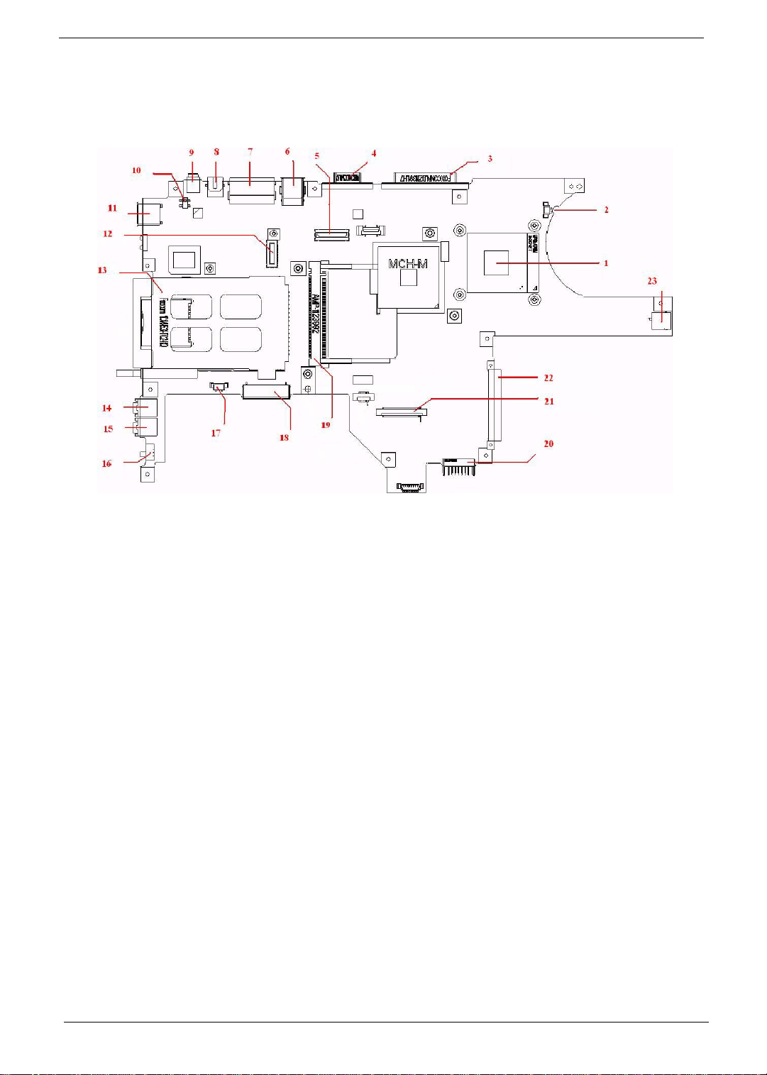
Board Layout
Top View
1-JP12 CPU Socket 13-JP15 PCMCIA Connector
2-JP7 FAN Connector 14-JP20 MIC in Jack
3-JP2 Parallel Port 15-JP23 Headphone out Jack
4-JP1 CRT Connector 16-SW3 Wireless Kill Switch
5-JP10 LCD Connector 17-JP18 Speakers Connector
6-JP6 USB Connectors (*2) 18-JP17 Module Connector
7-JP5 RJ11/RJ45 Connectors 19-JP13 Mini PCI Connector
8-JP4 S-Video Connector 20-PJP9 Battery Connector
9-JP3 IEEE 1394 Connector 21-JP21 Keyboard Connector
10-SW1 Lid Switch 22-JP22 HDD Connector
11-JP8 USB Connector 23-PCN1 DC-In Jack
12-JP11 MDC/MBC Connector
4 Chapter 1
Download Free Service Manual at http://printer1.blogspot.com
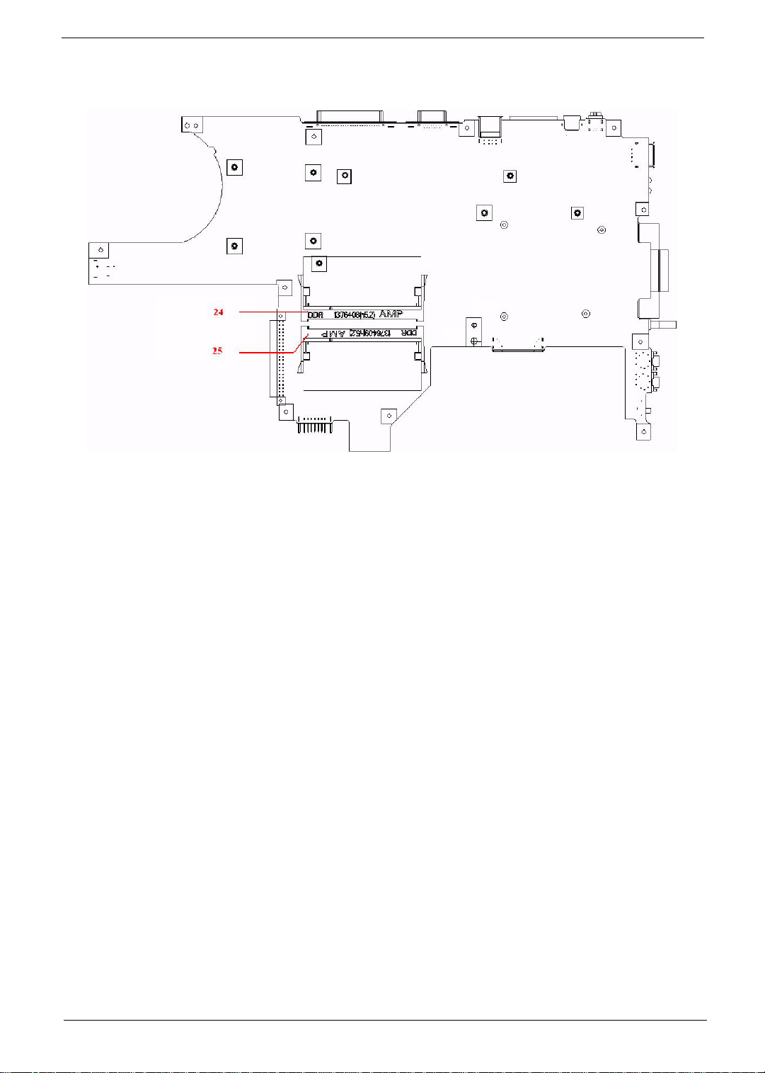
Bottom View
24-JP25 SO-DIMM Socket 25-JP26 SO-DIMM Socket
Chapter 1 5
Download Free Service Manual at http://printer1.blogspot.com
Outlook View
A general introduction of ports allow you to connect peripheral devices, as you would with a desktop PC.
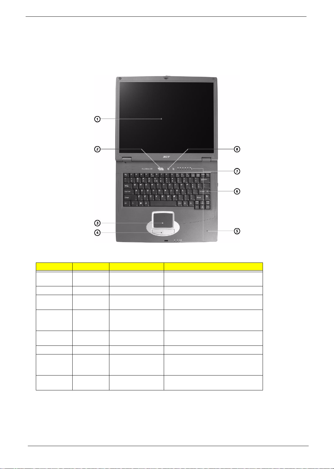
Front Open View
# Icon Item Description
1 Display screen Also called LCD (liquid-crystal display),
displays computer output.
2 Power Button Turns on the computer power.
3 Touchpad Touch-sensitive pointing device which
functions like a computer mouse.
4 Click buttons (left and
right)
5 Palmrest Comfortable support ares for your hands
6 Keyboard Inputs data into your computer.
7 Status indicators LEDs (light-emitting diode) that turn on and
8 Launch keys Two special keys for frequently used
The left and right buttons function like the
left and right mouse buttons; the center
button serves as a 4-way scroll button.
when you use the computer.
off to show the status of the computer, its
functions and components.
programs.
6 Chapter 1
Download Free Service Manual at http://printer1.blogspot.com
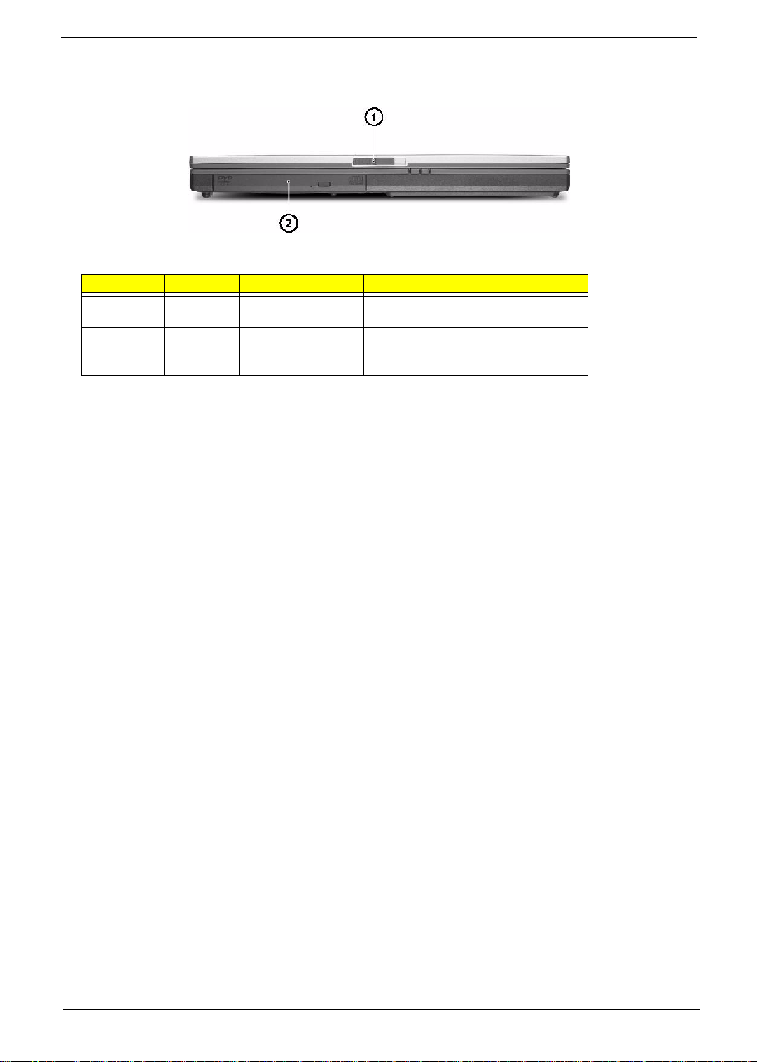
Front View
# Icon Item Description
1 Latch Latch for opening and colsing the
2 AcerMedia bay For hot-swappable modules including CD-
computer.
ROM, DVD-ROM, DVD/CD-RW combo or
DVD-RW.
Chapter 1 7
Download Free Service Manual at http://printer1.blogspot.com

Left Panel
# Icon Item Description
1 Infrared port Interfaces with infrared devices (e.g.,
2 PC card slot Accepts one Type II 16-bit PC card or 32-
infrared printer, IR-aware computer).
bit CardBus PC card.
3 Wireless
communication switch
4 Stereo speaker Outputs sound.
5 Headphone/Speaker/
Line-out jack
6 Microphone/Line-in
jack
7 One USB 2.0 port Connects to Universal Serial Bus devices
Enables and disables wireless
communication devices.
Connects to headphones or other line-out
audio devices (speakers).
Accepts input from external microphone, or
other audio line-in devices (e.g., audio CD
player, stereo walkman and etc.).
(e.g., USB mouse, USB camera).
8 Chapter 1
Download Free Service Manual at http://printer1.blogspot.com

Right Panel
# Icon Item Description
1 Stereo speaker Outputs sound.
2 HDD Houses the computer hard disk.
3 Ventialtion slot Enables the computer to stay cool, even
4 DC-in jack Connects the AC adapter.
after prolonged use.
Chapter 1 9
Download Free Service Manual at http://printer1.blogspot.com
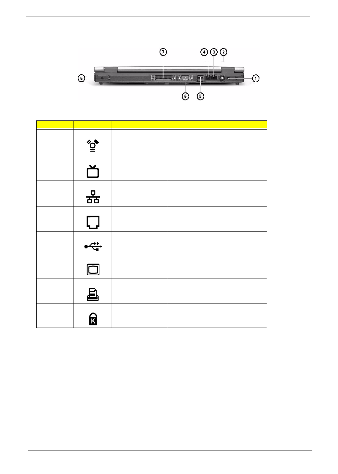
Rear Panel
# Icon Item Description
1 IEEE 1394 port Connects to IEEE 1394 devices.
2 S-video Connects to a television or display device
with S-video input.
3 Ethernet port Connects to an Ethernet 10/100-based
4 Modem port Connects to a phone line.
5 Two USB 2.0 ports Connects to Universal Serial Bus devices
6 External display port Connects to a display device (e.g., external
7 Parallel port Connects to a parallel device (e.g., parallel
8 Security keylock Connects to a Kensington-compatible
network.
(e.g., USB mouse, USB camera).
monitor, LCD projector).
printer).
computer security lock.
10 Chapter 1
Download Free Service Manual at http://printer1.blogspot.com
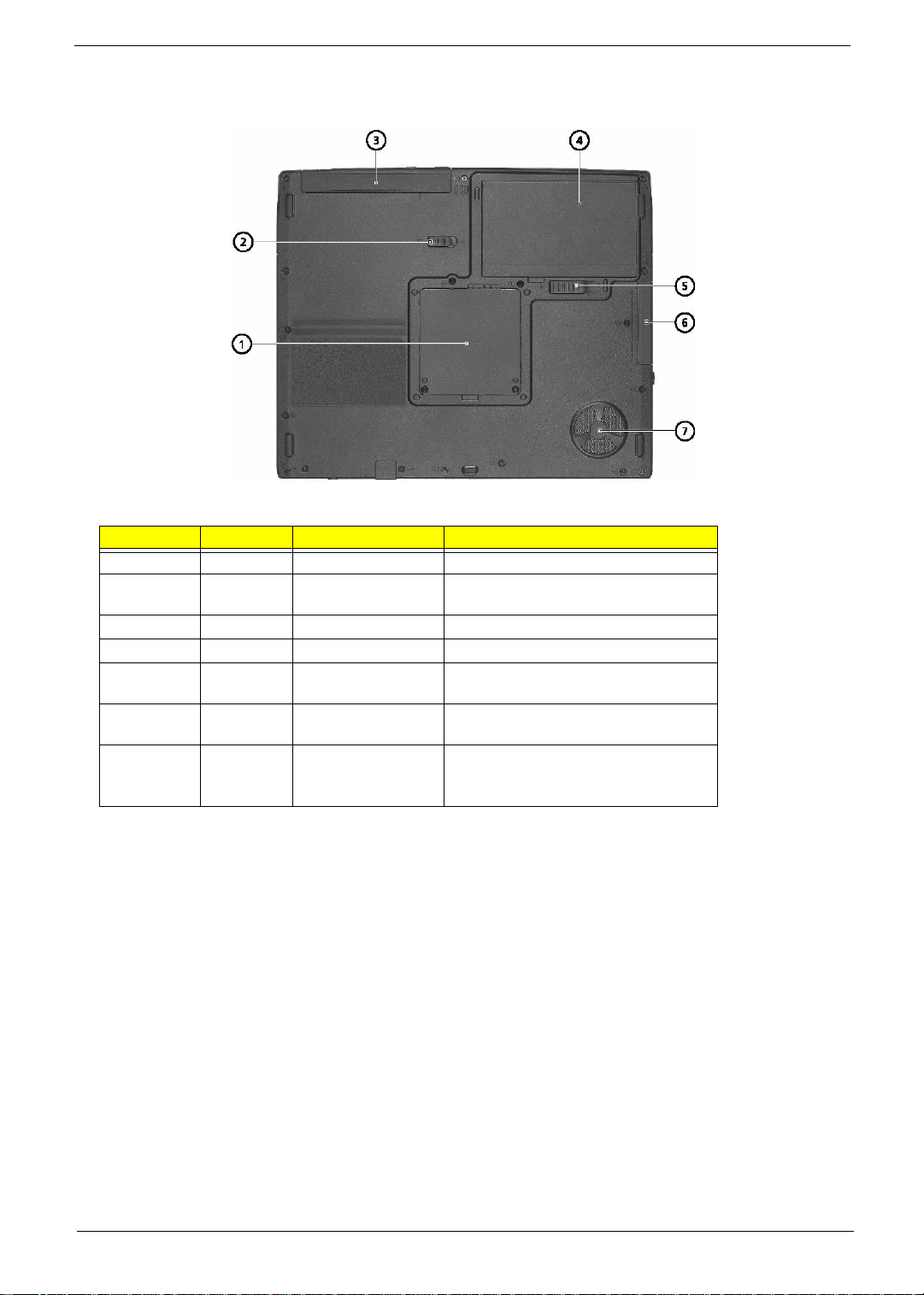
Bottom Panel
# Icon Item Description
1 Memory compartment Houses the computer’s main memory.
2 AcerMedia bay release
3 AcerMedia bay Houses an AcerMedia drive module.
4 Battery bay Houses the computer’s battery pack.
5 Battery release latch Unlatches the battery to remove the battery
6 Hard disk bay Houses the computer’s hard disk
7 Cooling fan Helps keep the computer cool.
latch
Unlatches the AcerMedia drive for
removing the optical drive.
pack.
(securedby a screw).
Note: Don’t cover or obstruct the opening
of the fan.
Chapter 1 11
Download Free Service Manual at http://printer1.blogspot.com
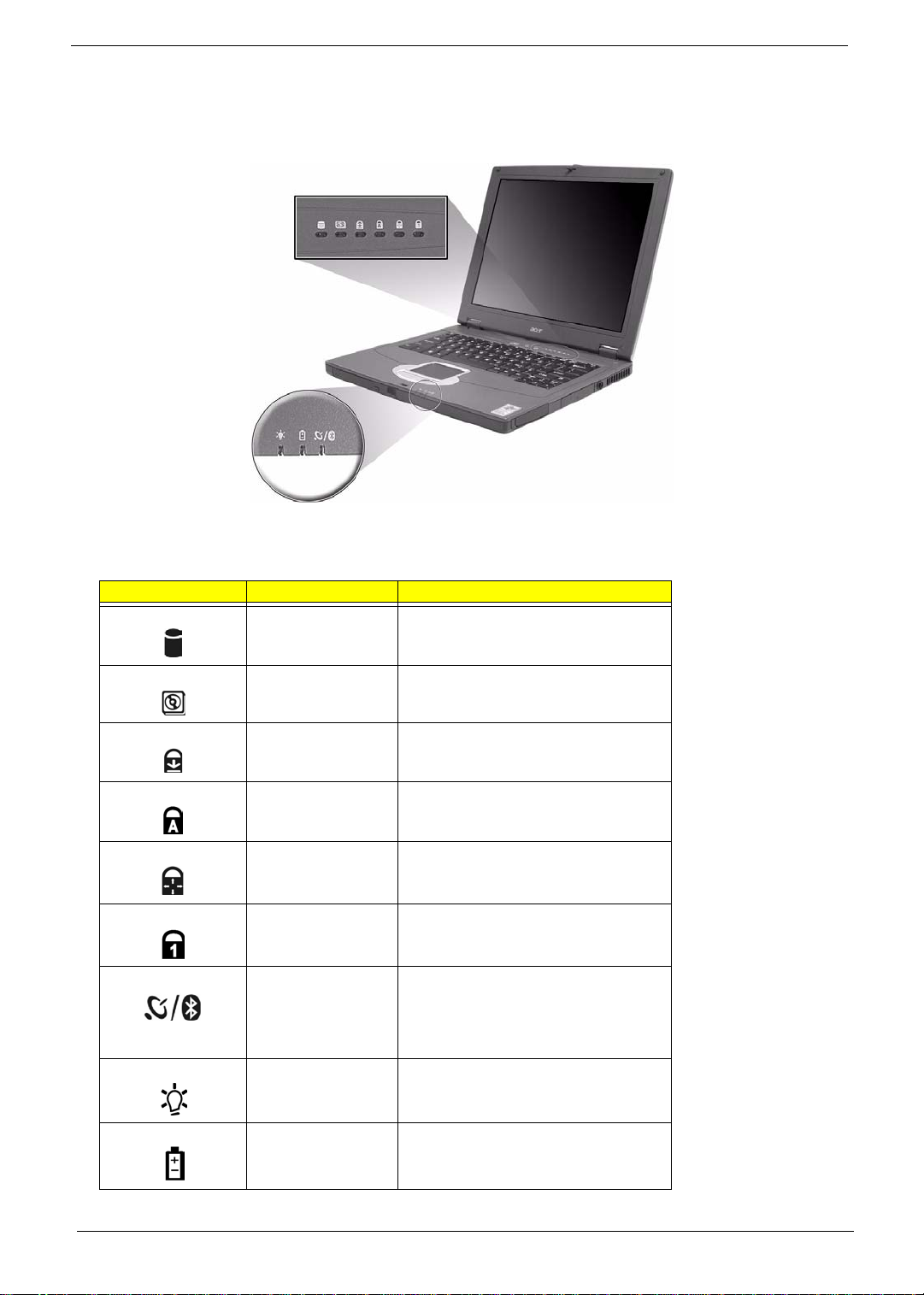
Indicators
The computer has seven easy-to-read status icons below the display screen.
The status LCD displays icons that show the status of the computer and its components.
Icon Function Description
HDD Lights when Hard Disk Drive is activated.
ODD Lights when Optical Disk Drive is activated.
Scroll lock Lights when Scroll Lock is activated.
Caps lock Lights when Caps Lock is activated.
Pad lock (cursor) Lights when Pad lock is activated.
Num lock Lights when Num Lock is activated.
Wireless/Bluetooth
indicator
Power Lights green when the power is on. Flashes
Orange indicators that wireless LAN is
enables; blue indicators that Bluetooth
(optional) is enabledLights when the
Wireless LAN or Bluetooth capabilities are
enabled.
when the computer is in standby mode.
Battery Lights green. Flashes when the battery is
being charged or low capacity.
12 Chapter 1
Download Free Service Manual at http://printer1.blogspot.com
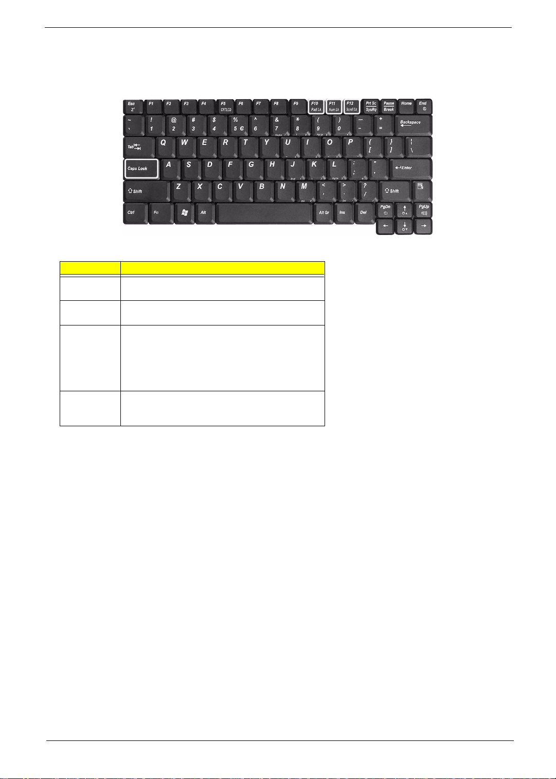
Lock Keys
The keyboard has four lock keys which you can toggle on and off.
Lock Key Description
Caps Lock When Caps Lock is on, all alphabetic characters typed
are in uppercase.
Pad lock
(Fn-F10)
Num lock
(Fn-F11)
Scroll lock
(Fn-F12)
When Pad Lock is on, the embedded keypad is
enabled. In this mode the keypad is cursor function.
When Num Lock is on, the embedded keypad is in
numeric mode. The keys function as a calculator
(complete with the arithmetic operators +, -, *, and /).
Use this mode when you need to do a lot of numeric
data entry. A better solution would be to connect an
external keypad.
When Scroll Lock is on, the screen moves one line up
or down when you press w and y respectively.
Scroll Lock does not work with some applications.
Chapter 1 13
Download Free Service Manual at http://printer1.blogspot.com
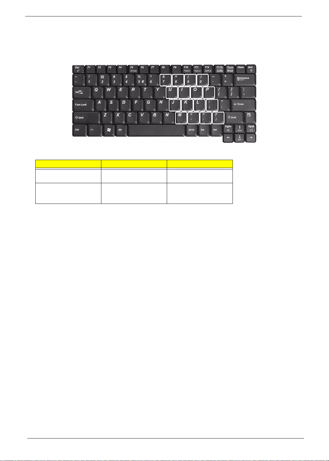
Embedded Numeric Keypad
The embedded numeric keypad functions like a desktop numeric keypad. It is indicated by small characters
located on the right hand side of the keycaps.
Desired Access Num Lock On Num Lock Off
Number keys on embedded
keypad
Main keyboard keys Hold <Fn> while typing
Type numbers in a normal
manner.
letters on embedded
keypad.
Type the letters in a normal
manner.
14 Chapter 1
Download Free Service Manual at http://printer1.blogspot.com
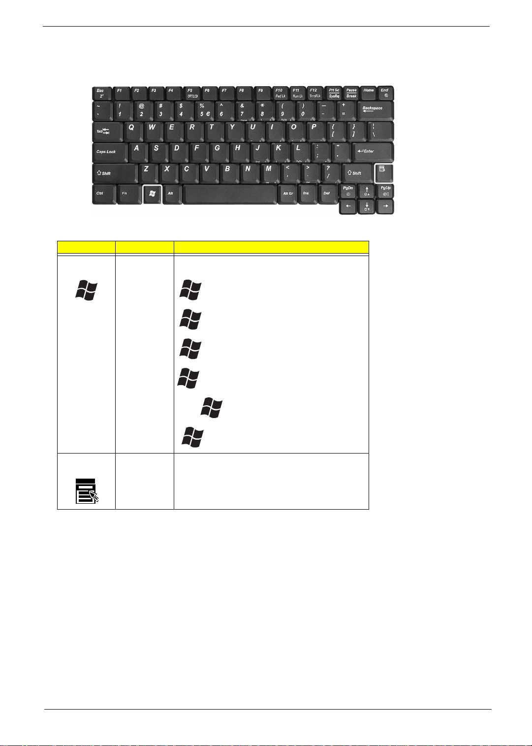
Windows Keys
The keyboard has two keys that perform Windows-specific functions.
Key Icon Description
Windows logo
key
Start button. Combinations with this key perform
special functions. Below are a few examples:
+ Tab (Activates next taskbar button)
+ E (Explores My Computer)
Application
key
+ F (Finds Document)
+ M (Minimizes All)
j + + M (Undoes Minimize All)
+ R (Displays the Run... dialog box)
Opens a context menu (same as a right-click).
Chapter 1 15
Download Free Service Manual at http://printer1.blogspot.com
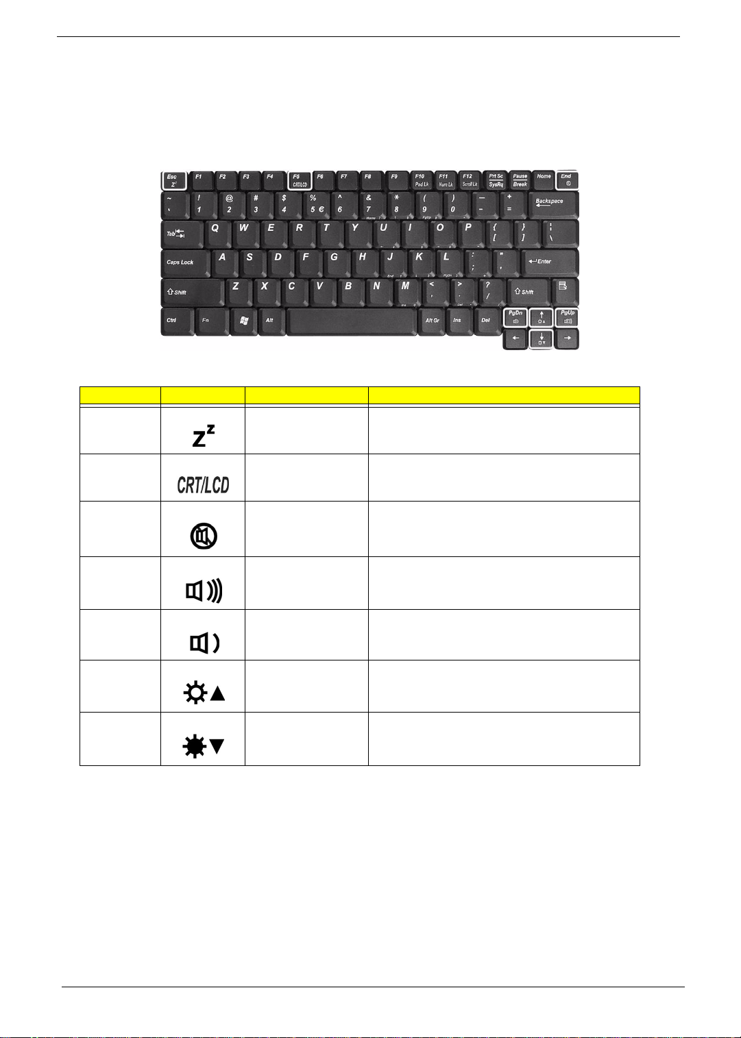
Hot Keys
The computer uses hotkey or key combinations to access most of the computer’s controls like sreen
brightness and volume output.
To activate hot keys, press and hold the Fn key before pressing the other key in the hot key combination.
Hot Key Icon Function Description
Fn-Esc Sleep Puts the computer in Sleep mode.
Fn-F5 Display toggle Switches display output between the display screen,
external monitor (if connected) and both the display
screen and external monitor.
Fn-End Speaker toggle Turns the speakers on and off.
Fn-PgUp Volume up Increases the speaker volume.
Fn-PgDn Volume down Decreases the speaker volume.
Fn-w Brightness up Increases the screen brightness.
Fn-y Brightness down Decreases the screen brightness
16 Chapter 1
Download Free Service Manual at http://printer1.blogspot.com
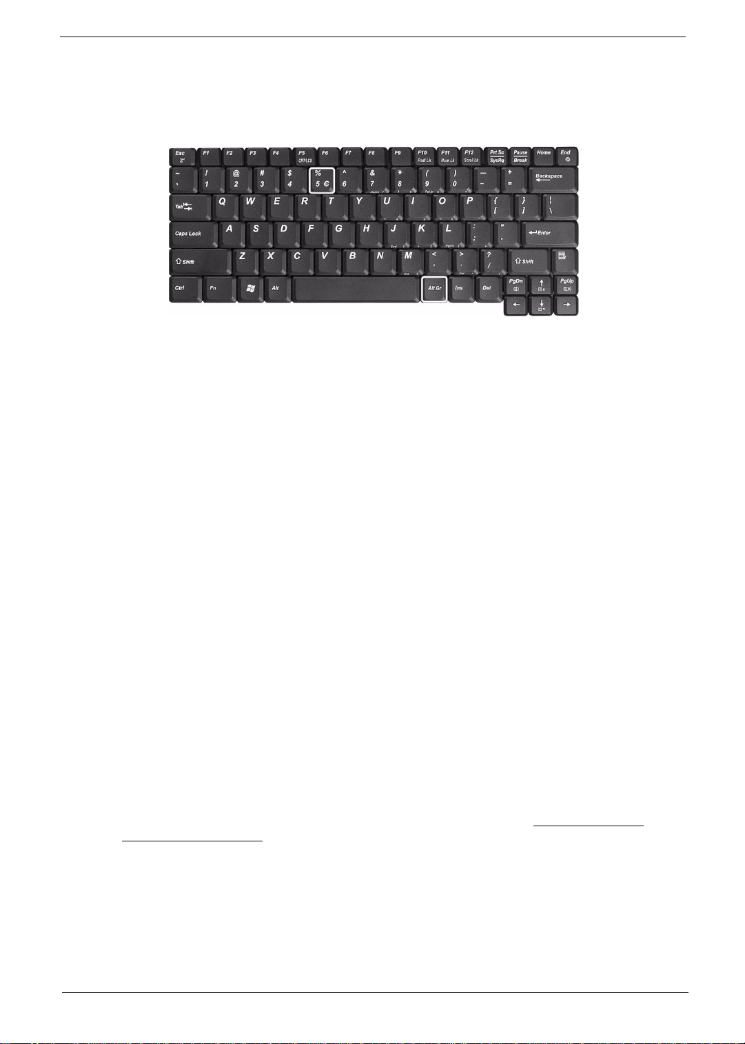
The Euro Symbol
If your keyboard layout is set to United States-International or United Kingdom or if you have a keyboard with a
European layout, you can type the Euro symbol on your keyboard.
NOTE: For US keyboard users: The keyboard layout is set when you first set up Windows. For the Euro
symbol to work, the keyboard layout has to be set to United States-International.
To verify the keyboard type in Windows 2000 and Windows Millennium Edition, follow the steps below:
1. Click on Start, Settings, Control Panel.
2. Double-click on Keyboard.
3. Click on the Language tab.
4. Verify that keyboard layout used for “En English (United States)” is set to United States-International. If
not, select and click on Properties; then select United States-International and click on OK.
5. Click on OK.
To verify the keyboard type in Windows XP, follow the steps below:
1. Click on Start, Control Panel.
2. Double-click on Regional and Language Options.
3. Click on the Language tab and click on Details.
4. Verify that the keyboard layout used for "En English (United States)" is set to United States-International.
If not, select and click on ADD; then select United States-International and click on OK.
5. Click on OK.
To type the Euro symbol:
1. Locate the Euro symbol on your keyboard.
2. Open a text editor or word processor.
3. Hold Alt Gr and press the Euro symbol.
NOTE: Some fonts and software do not support the Euro symbol. Please refer to www.microsoft.com/
typography/faq/faq12.htm for more information.
Chapter 1 17
Download Free Service Manual at http://printer1.blogspot.com
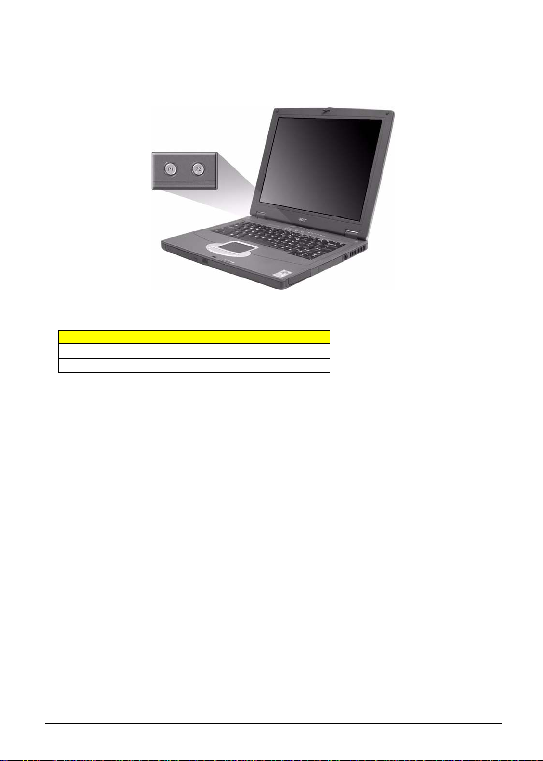
Launch Keys
Located at the top of keyboard are three buttons. The left-most button is the power button. To the right of the
power button are the two launch keys. They are designated as the programmable buttons (P1 and P2).
Launch Key Default application
P1 User-programmable
P2 User-programmable
18 Chapter 1
Download Free Service Manual at http://printer1.blogspot.com
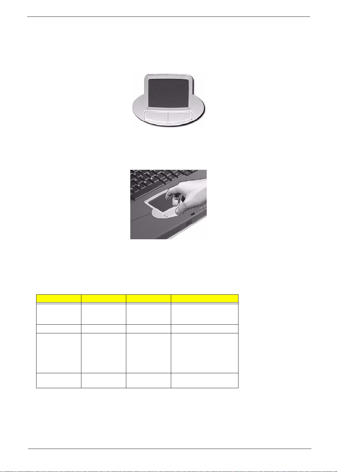
Touchpad
The built-in touchpad is a pointing device that senses movement on its surface. This means the cursor
responds as you move your finger on the surface of the touchpad. The central location on the palmrest
provides optimum comfort and support.
Touchpad Basics
The following items teach you how to use the touchpad:
T Move your finger across the touchpad to move the cursor.
T Press the left and right buttons located on the edge of the touchpad to do selection and execution
functions. These two buttons are similar to the left and right buttons on a mouse. Tapping on the
touchpad produces similar results.
Function Left Button Right Button Tap
Execute Click twice
Select Click once Tap once
Drag Click and hold,
Access context
menu
quickly
then use finger
to drag the
cursor on the
touchpad
Click once
Tap twice (at the same
speed as double-clicking
the mouse button)
Tap twice (at the same
speed as double-clicking
a mouse button) then hold
finger to the touchpad on
the second tap to drag the
cursor
NOTE: Keep your fingers dry and clean when using the touchpad. Also keep the touchpad dry and clean. The
touchpad is sensitive to finger movements. Hence, the lighter the touch, the better the response.
Tapping harder will not increase the touchpad’s responsiveness.
Chapter 1 19
Download Free Service Manual at http://printer1.blogspot.com
Hardware Specifications and Configurations
Processor
Item Specification
CPU type Intel Mobile Pentium M processor at 1.3~1.7 GHz or higher
CPU package uFCPGA package
CPU core voltage Support automatic selection of power supply voltage
CPU I/O voltage 1.05V
BIOS
Item Specification
BIOS vendor Insyde
BIOS Version Insyde MobilePRO BIOS 4.0
BIOS ROM type Flash ROM
BIOS ROM size 512KB
BIOS package 32 lead of PLCC
Bupported protocols ACPI 1.0b,PC Card 95, SM BIOS 2.3, EPP/IEEE 1284, ECP/IEEE 1284
1.7 & 1.9, PCI 2.2, PnP 1.0a, DMI 2.0, USB, VGA BIOS, CD-ROM bootable
BIOS password control Set by setup manual
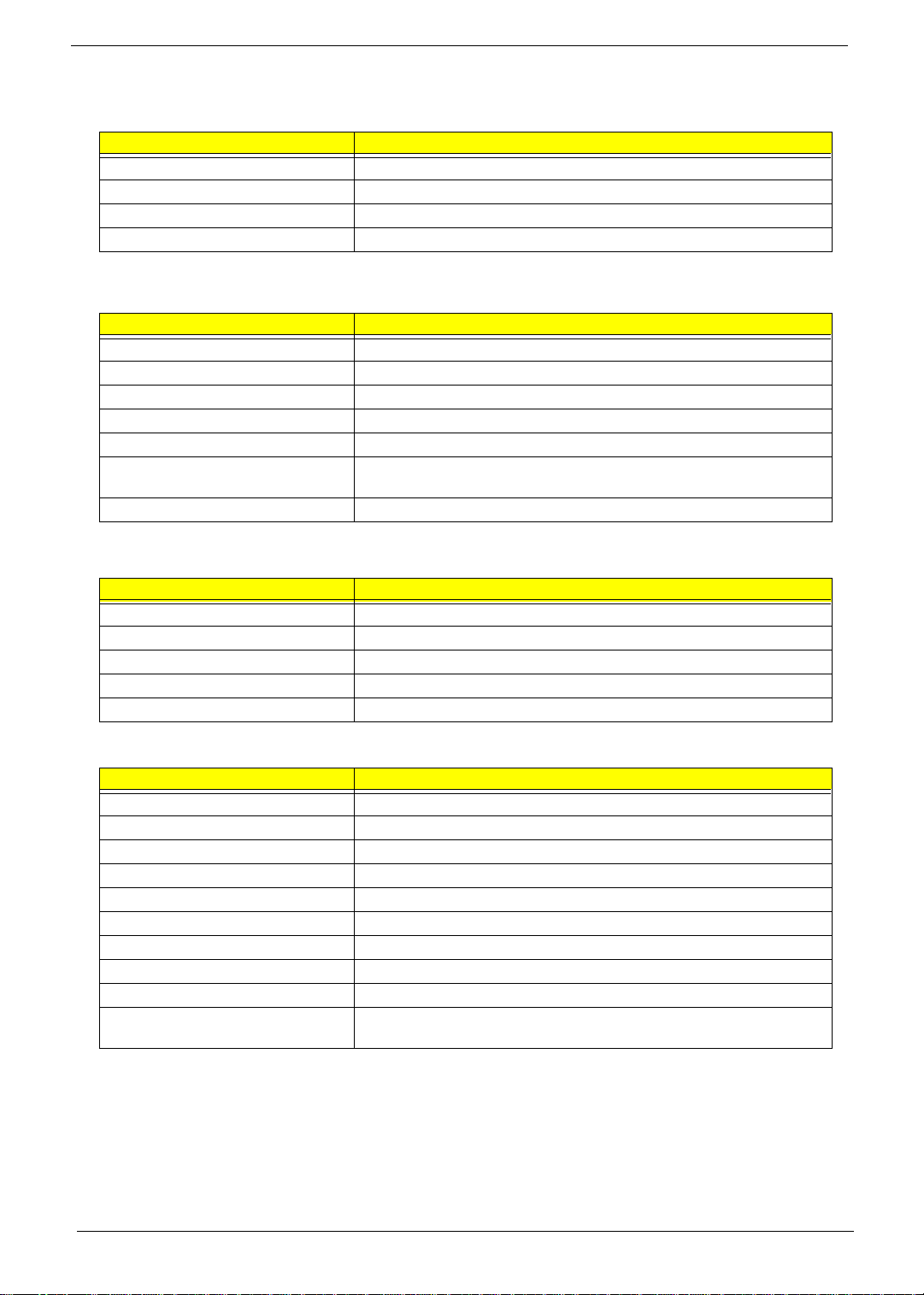
Second Level Cache
Item Specification
Cache controller Built-in CPU
Cache size 1MB
1st level cache control Always enabled
2nd level cache control Always enabled
Cache scheme control Fixed in write-through
System Memory
Item Specification
Memory controller Intel 855GM GMCH
Memory size 128MB/256MB/512MB/1GB
DIMM socket number 2 sockets
Supports memory size per socket 1024MB
Supports maximum memory size 2GB (by two 1024MB SO-DIMM module)
Supports DIMM type DDR Synchronous DRAM
Supports DIMM Speed 200/266 MHz
Supports DIMM voltage 2.5V
Supports DIMM package 200-pin SO-DIMM
Memory module combinations You can install memory modules in any combinations as long as they
match the above specifications.
20 Chapter 1
Download Free Service Manual at http://printer1.blogspot.com
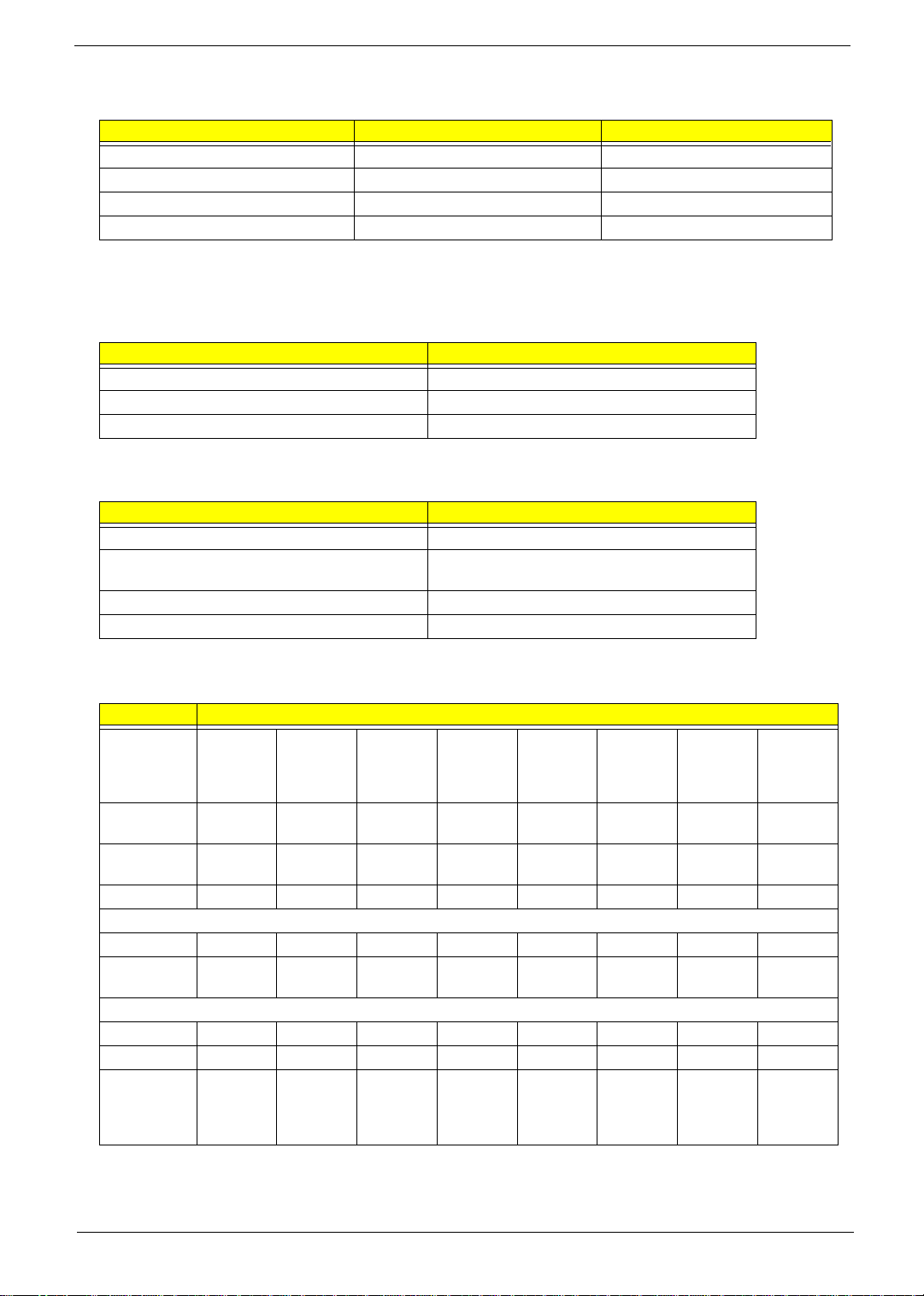
Memory Combinations
Slot 1 Slot 2 Total Memory
256/512MB 0 MB 256MB/512MB
256/512MB 128MB 384MB/640MB
256/512MB 256MB 512MB/768MB
256/512MB 512MB 768MB/1024MB
NOTE: Above table lists some system memory configurations. You may combine DIMMs with various
capacities to form other combinations.
.
LAN Interface
Item Specification
Supports LAN protocol 10/100 Mbps
LAN connector type RJ45
LAN connector location Rear side
.
Modem / Bluethooth Interface
Item Specification
Data modem data baud rate (bps) 56K
Supports modem/bluetooth protocol V.90 for MDC / Bluetooth 1.1 standard for BT
modem
Modem connector type RJ11
Modem connector location Rear side
Hard Disk Drive Interface
Item Specification
Vendor &
Model Name
Capacity
(MB)
Bytes per
sector
Data heads 2 2 3 4 1 2 2 3
Drive Format
Disks11221112
Spindle
speed (RPM)
Performance Specifications
Buffer size 2048KB 2048KB 2048KB 2048KB 2048KB 2048KB 2048KB 2048KB
Interface ATA-5 ATA-5 ATA-5 ATA-5 ATA-5 ATA-5 ATA-5 ATA-5
Max. media
transfer rate
(disk-buffer,
Mbytes/s)
Toshiba
20G
MK2023G
AS
20000 30000 40000 60000 20000 30000 40000 60000
512 512 512 512 512 512 512 512
4200 RPM 4200 RPM 4200 RPM 4200 RPM 4200 RPM 4200 RPM 4200 RPM 4200 RPM
164.6~
257.1
Toshiba
30G
MK3021G
AS
154.3~
298.0
Toshiba
40G
MK4021G
AS
154.3~
298.0
Toshiba
60G
MK6021G
AS
154.3~
298.0
Hitachi
20G
IC25N020
-ATMR04
350 350 350 350
Hitachi
30G
IC25N030
-ATMR04
Hitachi
40G
IC25N040
-ATMR04
Hitachi
60G
IC25N060
-ATMR04
Chapter 1 21
Download Free Service Manual at http://printer1.blogspot.com

Hard Disk Drive Interface
Item Specification
Data transfer
rate
(host~buffer,
Mbytes/s)
DC Power Requirements
Voltage
tolerance
100 MB/
Sec.
Ultra DMA
mode-5
5V(DC) +/
- 5%
100 MB/
Sec.
Ultra DMA
mode-5
5V(DC) +/
- 5%
100 MB/
Sec.
Ultra DMA
mode-5
5V(DC) +/
- 5%
100 MB/
Sec.
Ultra DMA
mode-5
5V(DC) +/
- 5%
100 MB/
Sec.
Ultra DMA
mode-5
5V(DC) +/
- 5%
100 MB/
Sec.
Ultra DMA
mode-5
5V(DC) +/
- 5%
100 MB/
Sec.
Ultra DMA
mode-5
5V(DC) +/
- 5%
DVD-ROM Interface
Item Specification
Vendor & model name Toshiba (SR-C2612)
Performance Specification With CD Diskette With DVD Diskette
Transfer rate (KB/sec) (Mode1)
4X-5.7X PCAV 600-855KByte/s
10.3X-24X CAV 1552-3600KByte/s
(Mode2)
4X-5.7X PACV 684.4-975.3KBytes/s
10.3X-24X CAV 1769-4104KByte/s
Data Buffer Capacity 192 KBytes
Interface IDE/ATAPI
Applicable disc format DVD: DVD-ROM (DVD-5, DVD-9, DVD-10, DVD-18),DVD-R (read, single
border), DVD-RW(read) DVD-RAM (read, Version2.1), DVD-RAM (read,
Version 1.0)
CD: CD-Audio, CD+(E)G, CD-MIDI, CD-TEXT, CD-ROM, CD-ROM XA, CD-I,
CD-I Bridge (Photo-CD, Video-CD) Multisession CD (Photo-CD, CD-EXTRA,
CD-R, CD-RW), CD-R (read), CD-RW (read)
Loading mechanism Load: Manual
Release: (a) Electrical Release (Release Button)
(b) Release by ATAPI command
(c) Emergency Release
Power Requirement
Input Voltage +5 V +/- 5 % (Operating)
+/- 8 % (Start up)
Input Voltage +5 V +/- 0.25V
3.3X-8X CAV 4463-10820KByte/s
Audio Interface
100 MB/
Sec.
Ultra DMA
mode-5
5V(DC) +/
- 5%
Item Specification
Audio Controller Realtek ALC202 AC97 Codec
Audio onboard or optional Built-in
Mono or Stereo Stereo
Resolution 20 bit stereo Digital to analog converter
18 bit stereo Analog to Ditial converter
Compatibility Microsoft PC99, AC97 2.2 & WHQL
Mixed sound source CD
Sampling rate 48 KHz
Internal microphone No
Internal speaker / Quantity Yes / 2
22 Chapter 1
Download Free Service Manual at http://printer1.blogspot.com
Loading...