


TM7300 Series
Notebook Computer
Service Guide
PART NO.: 49.42A01.001 |
|
DOC. NO.: SG238-9712A |
PRINTED IN TAIWAN |

Copyright
Copyright ã 1998 by Acer Incorporated. All rights reserved. No part of this publication may be reproduced, transmitted, transcribed, stored in a retrieval system, or translated into any language or computer language, in any form or by any means, electronic, mechanical, magnetic, optical, chemical, manual or otherwise, without the prior written permission of Acer Incorporated.
Disclaimer
Acer Incorporated makes no representations or warranties, either expressed or implied, with respect to the contents hereof and specifically disclaims any warranties of merchantability or fitness for any particular purpose. Any Acer Incorporated software described in this manual is sold or licensed "as is". Should the programs prove defective following their purchase, the buyer (and not Acer Incorporated, its distributor, or its dealer) assumes the entire cost of all necessary servicing, repair, and any incidental or consequential damages resulting from any defect in the software. Further, Acer Incorporated reserves the right to revise this publication and to make changes from time to time in the contents hereof without obligation of Acer Incorporated to notify any person of such revision or changes.
Intel is a registered trademark and Pentium is a trademark of Intel Corporation.
Other brand and product names are trademarks and/or registered trademarks of their respective holders.
ii

About this Manual
Purpose
This service guide aims to furnish technical information to the service engineers and advanced users when upgrading, configuring, or repairing the TM7300 series notebook computer.
Manual Structure
This service guide contains technical information about the TM7300 series notebook computer. It consists of three chapters and five appendices.
Chapter 1 System Introduction
This chapter describes the system features and major components. It contains the TM7300 series notebook computer board layout, block diagrams, cache and memory configurations, power management and mechanical specifications.
Chapter 2 Major Chips Description
This chapter describes the features and functions of the major chipsets used in the system board. It also includes chipset block diagrams, pin diagrams, and pin descriptions.
Chapter 3 BIOS Setup Utility
This chapter describes the parameters in the BIOS Utility screens.
Chapter 4 Disassembly and Unit Replacement
This chapter describes how to disassemble the TM7300 series notebook computer to make replacements or upgrades.
Appendix A Model Number Definition
This appendix shows the different configuration options for the TM7300 series notebook computer.
Appendix B Exploded View Diagram
This appendix illustrates the system board and CPU silk screens.
Appendix C |
Spare Parts List |
This appendix lists the spare parts for the TM7300 series notebook computer with their part numbers and other information.
iii
Appendix D |
Schematics |
This appendix contains the schematic diagrams for the system board.
Appendix E BIOS POST Checkpoints
This appendix lists and describes the BIOS POST checkpoints.
Conventions
The following are the conventions used in this manual:
Text entered by user
Screen messages
 ,
,  ,
,  , etc.
Represents text input by the user.
Denotes actual messages that appear onscreen.
Represent the actual keys that you have to press on the keyboard.
NOTE
Gives bits and pieces of additional information related to the current topic.
WARNING
Alerts you to any damage that might result from doing or not doing specific actions.
CAUTION
Gives precautionary measures to avoid possible hardware or software problems.
IMPORTANT
Reminds you to do specific actions relevant to the accomplishment of procedures.
TIP
Tells how to accomplish a procedure with minimum steps through little shortcuts.
iv

|
|
Table of Contents |
|
Chapter 1 |
System Introduction |
|
|
1.1 |
Features .............................................................................................................. |
1-1 |
|
|
1.1.2 |
FlashStart Automatic Power-On ............................................................ |
1-2 |
1.2 |
Ports .................................................................................................................... |
|
1-3 |
|
1.2.1 |
Rear Panel Ports................................................................................... |
1-3 |
|
1.2.2 |
Left Panel Ports .................................................................................... |
1-4 |
|
1.2.3 |
Indicator Lights...................................................................................... |
1-5 |
|
1.2.4 |
Hot Keys ............................................................................................... |
1-6 |
|
1.2.5 |
Automatic Tilt........................................................................................ |
1-8 |
1.3 |
System Specification Overview............................................................................ |
1-9 |
|
1.4 |
Board Layout ...................................................................................................... |
1-11 |
|
|
1.4.1 |
System Board (Top Side) ..................................................................... |
1-12 |
|
1.4.2 |
System Board (Bottom Side)................................................................ |
1-13 |
|
1.4.3 |
Media Board (Top Side) ....................................................................... |
1-14 |
|
1.4.4 |
Media Board (Bottom Side) .................................................................. |
1-15 |
1.5 |
Jumpers and Connectors .................................................................................... |
1-16 |
|
|
1.5.1 |
Mainboard............................................................................................ |
1-16 |
|
1.5.2 |
Media Board......................................................................................... |
1-18 |
1.6 |
System Configurations and Specifications .......................................................... |
1-19 |
|
|
1.6.1 |
System Memory Map ........................................................................... |
1-19 |
|
1.6.2 |
Interrupt Channel Map.......................................................................... |
1-19 |
|
1.6.3 |
I/O Address Map .................................................................................. |
1-19 |
|
1.6.4 |
DMA Channel Map............................................................................... |
1-20 |
|
1.6.5 |
GPIO Port Definition Map..................................................................... |
1-21 |
|
1.6.6 |
PCI Devices Assignment...................................................................... |
1-25 |
|
1.6.7 |
Power Management ............................................................................. |
1-25 |
|
1.6.8 |
CPU Module......................................................................................... |
1-31 |
|
1.6.9 |
BIOS.................................................................................................... |
1-32 |
|
1.6.10 |
System Memory ................................................................................... |
1-32 |
|
1.6.11 |
Video Memory...................................................................................... |
1-33 |
|
1.6.12 |
Video Display Modes............................................................................ |
1-34 |
|
1.6.13 |
Audio ................................................................................................... |
1-35 |
v

|
1.6.14 |
PCMCIA............................................................................................... |
1-35 |
|
1.6.15 |
Parallel Port ......................................................................................... |
1-36 |
|
1.6.16 |
Serial Port............................................................................................ |
1-36 |
|
1.6.17 |
Touchpad............................................................................................. |
1-36 |
|
1.6.18 |
SIR/FIR................................................................................................ |
1-37 |
|
1.6.19 |
LCD ..................................................................................................... |
1-37 |
|
1.6.20 |
CD-ROM.............................................................................................. |
1-38 |
|
1.6.21 |
Diskette Drive ...................................................................................... |
1-38 |
|
1.6.22 |
Hard Disk Drive.................................................................................... |
1-39 |
|
1.6.23 |
Keyboard ............................................................................................. |
1-39 |
|
1.6.24 |
Battery ................................................................................................. |
1-40 |
|
1.6.25 |
DC-DC Converter................................................................................. |
1-40 |
|
1.6.26 |
DC-AC Inverter .................................................................................... |
1-41 |
|
1.6.27 |
AC Adapter .......................................................................................... |
1-41 |
1.7 |
System Block Diagrams...................................................................................... |
1-42 |
|
|
1.7.1 |
System Functional Block Diagram........................................................ |
1-42 |
|
1.7.2 |
System Bus Block Diagram.................................................................. |
1-43 |
1.8 |
Environmental Requirements.............................................................................. |
1-44 |
|
1.9 |
Mechanical Specifications................................................................................... |
1-45 |
|
Chapter 2 |
Major Chips Description |
|
|
2.1 |
Major Component List........................................................................................... |
2-1 |
|
2.2 |
Intel PIIX4............................................................................................................. |
2-2 |
|
|
2.2.1 |
Features ................................................................................................. |
2-4 |
|
2.2.2 |
Architecture Block Diagram .................................................................... |
2-6 |
|
2.2.3 |
Block Diagram ....................................................................................... |
2-7 |
|
2.2.4 |
Pin Descriptions ..................................................................................... |
2-8 |
2.3 |
NM2160.............................................................................................................. |
2-28 |
|
|
2.3.1 |
Features ............................................................................................... |
2-28 |
|
2.3.2 |
Pin Diagram ......................................................................................... |
2-30 |
|
2.3.3 |
Pin Descriptions ................................................................................... |
2-31 |
2.4 |
NMA1 |
................................................................................................................. |
2-38 |
|
2.4.1 ............................................................................................... |
Features |
2-38 |
|
2.4.2 ..................................................................................... |
Block Diagram |
2-39 |
vi

|
2.4.3 |
Pin Diagram ......................................................................................... |
2-40 |
|
2.4.4 |
Pin Descriptions ................................................................................... |
2-41 |
2.5 |
Philips 87C552 System Management Controller ................................................. |
2-43 |
|
|
2.5.1 |
Features............................................................................................... |
2-43 |
|
2.5.2 |
Block Diagram ..................................................................................... |
2-44 |
|
2.5.3 |
Pin Diagram ......................................................................................... |
2-45 |
|
2.5.4 |
Pin Descriptions ................................................................................... |
2-46 |
2.6 |
NS87338VJG Super I/O Controller...................................................................... |
2-48 |
|
|
2.6.1 |
Features............................................................................................... |
2-48 |
|
2.6.2 |
Block Diagram ..................................................................................... |
2-50 |
|
2.6.3 |
Pin Diagram ......................................................................................... |
2-51 |
|
2.6.4 |
Pin Description..................................................................................... |
2-52 |
2.7 |
CL-PD6832: PCI-to-CardBus Host Adapter ......................................................... |
2-59 |
|
|
2.7.1 |
Features............................................................................................... |
2-59 |
|
2.7.2 |
Pin Diagram ......................................................................................... |
2-60 |
|
2.7.3 |
Pin Descriptions ................................................................................... |
2-60 |
2.8 |
Ambit T62.036.C DC-DC Converter .................................................................... |
2-72 |
|
|
2.8.1 |
Pin Diagram ......................................................................................... |
2-72 |
|
2.8.2 |
Pin Descriptions ................................................................................... |
2-72 |
2.9 |
Ambit DC-AC Inverter ......................................................................................... |
2-74 |
|
|
2.9.1 |
T62.055C ............................................................................................. |
2-74 |
|
2.9.2 |
T62.088C ............................................................................................. |
2-75 |
Chapter 3 |
BIOS Setup Utility |
|
|
3.1 |
About My Computer ............................................................................................. |
3-2 |
|
3.2 |
System Configuration........................................................................................... |
3-3 |
|
|
3.2.1 |
Date and Time ...................................................................................... |
3-3 |
|
3.2.2 |
Floppy Drives........................................................................................ |
3-3 |
|
3.2.3 |
Hard Disks ............................................................................................ |
3-3 |
|
3.2.4 |
Num Lock After Boot............................................................................. |
3-3 |
|
3.2.5 |
LCD Expansion Mode ........................................................................... |
3-3 |
|
3.2.6 |
Internal Speaker.................................................................................... |
3-4 |
|
3.2.7 |
Silent Boot ............................................................................................ |
3-4 |
|
3.2.8 |
Fast Boot ................................................................................................ |
3- |
vii

3.3 |
Advanced System Configuration........................................................................... |
3-5 |
|
|
3.3.1 |
Internal Cache........................................................................................ |
3-5 |
|
3.3.2 |
External Cache ...................................................................................... |
3-5 |
|
3.3.3 |
Enhanced IDE Features ......................................................................... |
3-5 |
|
3.3.4 |
Onboard Communication Ports .............................................................. |
3-6 |
|
3.3.5 |
Onboard USB......................................................................................... |
3-6 |
|
3.3.6 |
Reset PnP Resources ............................................................................ |
3-7 |
3.4 |
Power Saving Options .......................................................................................... |
3-8 |
|
|
3.4.1 |
When Lid is Closed ................................................................................ |
3-8 |
|
3.4.2 |
Suspend to Disk on Critical Battery ........................................................ |
3-8 |
|
3.4.3 |
Display Always On ................................................................................. |
3-8 |
|
3.4.4 |
Resume On Modem Rings ..................................................................... |
3-8 |
|
3.4.5 |
Resume On Schedule ............................................................................ |
3-9 |
3.5 |
System Security.................................................................................................. |
3-10 |
|
|
3.5.1 |
Supervisor and User Passwords........................................................... |
3-10 |
|
3.5.2 |
Diskette Drive Access Control .............................................................. |
3-11 |
|
3.5.3 |
Hard Disk Drive Access Control ........................................................... |
3-11 |
|
3.5.4 |
Start Up Sequences ............................................................................. |
3-11 |
|
3.5.5 |
Refresh New BIOS............................................................................... |
3-11 |
3.6 |
Reset To Default Settings ................................................................................... |
3-12 |
|
Chapter 4 |
Disassembly and Unit Replacement |
|
|
4.1 |
General Information.............................................................................................. |
4-1 |
|
|
4.1.1 |
Before You Begin................................................................................... |
4-1 |
|
4.1.2 |
Connector Types.................................................................................... |
4-3 |
|
4.1.3 |
Disassembly Sequence .......................................................................... |
4-4 |
4.2 |
Removing the Module........................................................................................... |
4-6 |
|
4.3 |
Replacing the Hard Disk Drive .............................................................................. |
4-7 |
|
4.4 |
Replacing Memory................................................................................................ |
4-8 |
|
4.5 |
Removing the Keyboard ..................................................................................... |
4-10 |
|
4.6 |
Replacing the CPU ............................................................................................. |
4-12 |
|
4.7 |
Removing the Display......................................................................................... |
4-13 |
|
4.8 |
Disassembling the Housing................................................................................. |
4-14 |
|
viii

|
4.8.1 |
Detaching the Lower Housing from the Inside Assembly ...................... |
4-14 |
|
4.8.2 |
Detaching the Upper Housing from the Inside Assembly ...................... |
4-15 |
|
4.8.3 |
Removing the Touchpad ...................................................................... |
4-16 |
|
4.8.4 |
Removing the Main Board.................................................................... |
4-16 |
4.9 |
Disassembling the Display .................................................................................. |
4-19 |
|
Appendices
Appendix A Model Number Definition
Appendix B Exploded View Diagram
Appendix C Spare Parts List
Appendix D Schematics
Appendix E BIOS POST Checkpoints
ix

List of |
Figures |
|
1-1 |
Lid Switch ............................................................................................................. |
1-2 |
1-2 |
Rear Port Location................................................................................................ |
1-3 |
1-3 |
Left Port Location ................................................................................................. |
1-4 |
1-4 |
Indicator Lights ..................................................................................................... |
1-5 |
1-5 |
System Board (Top Side).................................................................................... |
1-12 |
1-6 |
System Board (Bottom Side)............................................................................... |
1-13 |
1-7 |
Media Board (Top Side)...................................................................................... |
1-14 |
1-8 |
Media Board (Bottom Side)................................................................................. |
1-15 |
1-9 |
Mainboard Jumpers and Connectors (Top Side) ................................................. |
1-16 |
1-10 |
Mainboard Jumpers and Connectors (Bottom Side) ............................................ |
1-17 |
1-11 |
Media Board Jumpers and Connectors (Top Side) .............................................. |
1-18 |
1-12 |
Media Board Jumpers and Connectors (Bottom Side) ......................................... |
1-18 |
1-13 |
System Functional Block Diagram ...................................................................... |
1-42 |
1-14 |
System Bus Block Diagram................................................................................. |
1-43 |
2-1 |
PIIX4 Architecture Block Diagram ......................................................................... |
2-6 |
2-2 |
PIIX4 Simplified Block Diagram ............................................................................ |
2-7 |
2-3 |
NM2160 Pin Diagram.......................................................................................... |
2-30 |
2-4 |
NMA1 Block Diagram ......................................................................................... |
2-39 |
2-5 |
NMA1 Pin Diagram ............................................................................................. |
2-40 |
2-6 |
87C552 Block Diagram ....................................................................................... |
2-44 |
2-7 |
87C552 Pin Diagram........................................................................................... |
2-45 |
2-8 |
NS87338VJG Block Diagram.............................................................................. |
2-50 |
2-9 |
NS87338VJG Pin Diagram ................................................................................. |
2-51 |
2-10 |
CL-PD6832 Pin Diagram..................................................................................... |
2-60 |
2-11 |
T62.036.C Pin Diagram ...................................................................................... |
2-72 |
2-12 |
T62.055.C Pin Diagram ...................................................................................... |
2-74 |
2-13 |
T62.088.C Pin Diagram ...................................................................................... |
2-75 |
4-1 |
Removing the Battery Pack .................................................................................. |
4-2 |
4-2 |
Using Plastic Stick on Connector With Locks ........................................................ |
4-3 |
4-3 |
Disassembly Flow ................................................................................................. |
4-5 |
4-4 |
Removing the Module........................................................................................... |
4-6 |
4-5 |
Removing the Hard Disk Drive Bay Cover ............................................................ |
4-7 |
4-6 |
Removing the Hard Disk Drive.............................................................................. |
4-7 |
4-7 |
Installing a Memory Module .................................................................................. |
4-8 |
x
4-8 |
Installing and Removing Memory......................................................................... |
4-8 |
4-9 |
Removing the Display Hinge Covers................................................................... |
4-10 |
4-10 |
Removing the Center Hinge Cover ..................................................................... |
4-10 |
4-11 |
Lifting Out the Keyboard ..................................................................................... |
4-11 |
4-12 |
Unplugging the Keyboard Connectors and Removing the Keyboard.................... |
4-11 |
4-13 |
Removing the CPU Heat Sink............................................................................. |
4-12 |
4-14 |
Removing the CPU Module................................................................................. |
4-12 |
4-15 |
Unplugging the Display Cable ............................................................................. |
4-13 |
4-16 |
Removing the Display Hinge Screws and Removing the Display......................... |
4-13 |
4-17 |
Removing the Lower Housing ............................................................................. |
4-14 |
4-18 |
Removing the Battery Bay Screws ...................................................................... |
4-15 |
4-19 |
Detaching the Upper Housing from the Inside Frame Assembly .......................... |
4-15 |
4-20 |
Removing the Touchpad..................................................................................... |
4-16 |
4-21 |
Unplugging the Speaker Connectors and Battery Pack Connector ...................... |
4-16 |
4-22 |
Removing the Main Board .................................................................................. |
4-17 |
4-23 |
Removing the Charger Board and Multimedia Board .......................................... |
4-17 |
4-24 |
Removing the PC Card Slots .............................................................................. |
4-18 |
4-25 |
Removing the LCD Bumpers .............................................................................. |
4-19 |
4-26 |
Removing the Display Bezel Screws................................................................... |
4-19 |
4-27 |
Removing the Display Bezel ............................................................................... |
4-20 |
4-28 |
Removing the Display Panel Screws and the Display Connectors ....................... |
4-20 |
4-29 |
Removing the Display Cable Assembly............................................................... |
4-21 |
xi

List of |
Tables |
|
1-1 |
Rear Port Descriptions .......................................................................................... |
1-3 |
1-2 |
Left Port Descriptions............................................................................................ |
1-5 |
1-3 |
Indicator Light Descriptions................................................................................... |
1-5 |
1-4 |
Hot Key Descriptions ............................................................................................ |
1-6 |
1-5 |
Eject Menu Item Descriptions ............................................................................... |
1-7 |
1-6 |
System Specifications........................................................................................... |
1-9 |
1-7 |
Mainboard Jumpers Pads Settings (Bottom Side) ............................................... |
1-17 |
1-8 |
System Memory Map.......................................................................................... |
1-19 |
1-9 |
Interrupt Channel Map ........................................................................................ |
1-19 |
1-10 |
I/O Address Map................................................................................................. |
1-19 |
1-11 |
DMA Channel Map.............................................................................................. |
1-20 |
1-12 |
GPIO Port Definition Map I ................................................................................. |
1-21 |
1-13 |
GPIO Port Definition Map II ................................................................................ |
1-22 |
1-14 |
PCI Devices Assignment .................................................................................... |
1-25 |
1-15 |
PMU Timers List ................................................................................................. |
1-26 |
1-16 |
CPU Module Specifications................................................................................. |
1-31 |
1-17 |
BIOS Specifications............................................................................................ |
1-32 |
1-18 |
System Memory Specifications ........................................................................... |
1-32 |
1-19 |
SIMM Memory Combination List ......................................................................... |
1-33 |
1-20 |
Video Memory Specification ............................................................................... |
1-33 |
1-21 |
Video Display Specification................................................................................. |
1-34 |
1-22 |
External CRT Resolution Modes ......................................................................... |
1-34 |
1-23 |
LCD Resolution Modes ....................................................................................... |
1-34 |
1-24 |
Audio Specifications ........................................................................................... |
1-35 |
1-25 |
PCMCIA Specifications....................................................................................... |
1-35 |
1-26 |
Parallel Port Specifications ................................................................................. |
1-36 |
1-27 |
Serial Port Specifications.................................................................................... |
1-36 |
1-28 |
Touchpad Specifications..................................................................................... |
1-36 |
1-29 |
SIR/FIR Specifications........................................................................................ |
1-37 |
1-30 |
LCD Specifications ............................................................................................. |
1-37 |
1-31 |
CD-ROM Specifications ...................................................................................... |
1-38 |
1-32 |
Diskette Drive Specifications .............................................................................. |
1-38 |
1-33 |
Hard Disk Drive Specifications............................................................................ |
1-39 |
1-34 |
Keyboard Specifications ..................................................................................... |
1-39 |
xii

1-35 |
Battery Specifications ......................................................................................... |
1-40 |
1-36 |
DC-DC Converter Specifications......................................................................... |
1-40 |
1-37 |
DC-AC Inverter Specifications ............................................................................ |
1-41 |
1-38 |
AC Adapter Specifications .................................................................................. |
1-41 |
1-39 |
Environmental Requirements.............................................................................. |
1-44 |
1-40 |
Mechanical Specifications................................................................................... |
1-45 |
2-1 |
Major Chips List ................................................................................................... |
2-1 |
2-2 |
82371AB Pin Descriptions.................................................................................... |
2-9 |
2-3 |
NM2160 Pin Descriptions.................................................................................... |
2-31 |
2-4 |
NMA1 Pin Descriptions ....................................................................................... |
2-41 |
2-5 |
87C552 Pin Descriptions..................................................................................... |
2-46 |
2-6 |
NS87338VJG Pin Descriptions............................................................................ |
2-52 |
2-7 |
CL-PD6832 Pin Descriptions............................................................................... |
2-62 |
2-8 |
T62.036.C Pin Descriptions................................................................................. |
2-72 |
2-9 |
T62.055.C Pin Descriptions................................................................................. |
2-74 |
2-10 |
T62.088.C Pin Descriptions................................................................................. |
2-75 |
3-1 |
About My Computer Parameters .......................................................................... |
3-2 |
3-2 |
Start Up Sequences ............................................................................................ |
3-11 |
4-1 |
Guide to Disassembly Sequence.......................................................................... |
4-4 |
B-1 |
Exploded View Diagram List ................................................................................ |
B-1 |
C-1 |
Spare Parts List ................................................................................................... |
C-1 |
D-1 |
Schematics Diagram List ..................................................................................... |
D-1 |
E-1 |
POST Checkpoint List.......................................................................................... |
E-1 |
xiii

& K D S W H U
System Introduction
The computer is packed with features that make it as easy to work with as it is to look at. Here are some of the computer’s features:
1.1Features
PERFORMANCE
∙Intel Pentium® II 266 MHz processor
∙64-bit main memory and 512KB external (L2) cache memory
∙Large display in active-matrix TFT
∙PCI local bus video with 128-bit graphics accelerator
∙Flexible module bay (3.5-inch floppy drive or CD-ROM drive or DVD-ROM drive or LS120 or second hard disk drive option)
∙High-capacity, Enhanced-IDE hard disk
∙An advanced power management system with two power-saving modes
∙Lithium-Ion smart battery pack
∙High-speed connectivity
MULTIMEDIA AND COMMUNICATIONS
∙16-bit stereo audio with built-in FM synthesizer and 3D sound effect
∙Built-in microphone and dual angled stereo speakers
∙Support for simultaneous display on the built-in screen and an external monitor for presentations
∙Full-screen, 30 frames per second, true-color MPEG video playback
∙Infrared wireless communication
ERGONOMICS
∙Intuitive FlashStart automatic power-on
∙Sleek, smooth and stylish design
∙Automatic tilt-up (12.1-inch models only), full-sized, full-function keyboard
∙Wide and comfortable palm rest
System Introduction |
1-1 |
∙Ergonomically-positioned touchpad pointing device
EXPANDABILITY
∙CardBus PC Card (PCMCIA) slots (two type II/I or one type III) with Zoomed Video port function
∙Mini-dock option with two CardBus PC Card slots (two type II/I or one type III)
∙USB port onboard
∙Upgradeable memory and hard disk
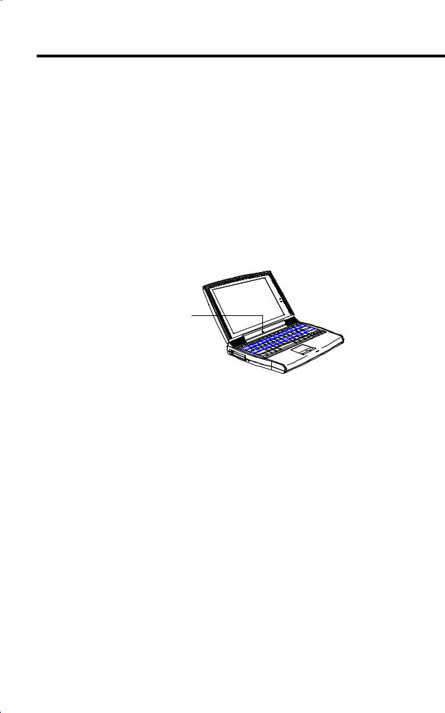
1.1.2FlashStart Automatic Power-On
The computer has no on/off switch. Instead it uses a lid switch, located near the center of the display hinge, that turns the computer on and off automatically.
Lid Switch
Figure 1-1 |
Lid Switch |
When you close the display lid, the computer saves all data either to the hard disk or to memory, depending on the When Lid Is Closed setting (see section 3.4.1). When all data is saved, the computer turns itself off. When you reopen the lid, the computer retrieves your data and resumes where you left off.
1-2 |
Service Guide |

1.2Ports
The computer’s ports allow you to connect peripheral devices to your computer just as you would to a desktop PC. The main ports are found on the computer’s rear panel. The computer’s left panel contains the computer’s multimedia ports and PC card slots.
1.2.1Rear Panel Ports
The computer’s rear panel contains the computer’s main ports and connectors as shown in the illustration below.
|
|
1 |
2 |
|
|
|
|
|
3 |
4 |
|
|
|
|
|
5 |
|
|
|
|
|
6 7 |
8 |
1 |
DC-in Port |
|
|
|
|
2 |
PS/2 Port |
|
|
|
|
3 |
Serial Port |
|
|
|
|
4 |
Parallel Port |
|
|
|
|
5 |
Mini Dock Connector |
|
|
|
|
6 |
External CRT Port |
|
|
|
|
7 |
USB Port |
|
|
|
|
8 |
Infrared Port |
|
|
|
|
Figure 1-2 |
Rear Port Location |
|
|
|
|
|
Table 1-1 |
Rear Port Descriptions |
|
|
|
|
Port |
Icon |
|
|
Connects to... |
|
DC-in port |
|
AC adapter and power outlet |
||
|
PS/2 port |
|
PS/2-compatible device |
||
|
|
|
(PS/2 keyboard, keypad, mouse) |
||
|
Serial port |
|
Serial device (serial mouse) |
||
|
(UART16650-compatible) |
|
|
|
|
|
Parallel port (EPP/ECP- |
Parallel device (parallel printer, external floppy drive) |
|||
|
compliant) |
|
|
|
|
|
Mini dock connector |
Mini dock |
|
||
|
External CRT port |
External monitor (up to 1024x768x256 colors) |
|||
|
USB port |
|
USB device (USB mouse, keyboard) |
||
|
Infrared port |
|
Infrared-aware device (computer with IR port, desktop with IR |
||
|
|
|
adapter, IR-capable printer) |
||
System Introduction |
1-3 |
UNIVERSAL SERIAL BUS (USB) PORT
The computer’s USB (Universal Serial Bus) port located on the rear panel allows you to connect peripherals without occupying too many resources. Common USB devices include the mouse and keyboard.
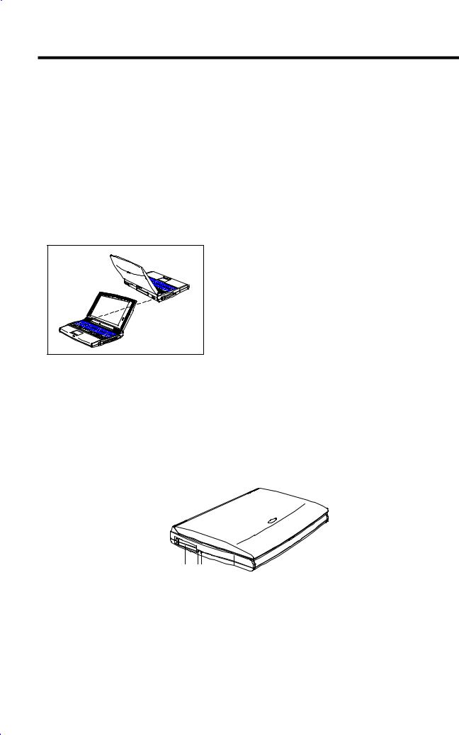
FAST INFRARED (FIR) PORT
The computer’s FIR (fast infrared) port located on the rear panel allows you to transfer data to IRaware machines without cables. For example, you can transfer data between two IR-capable computers, or send data to an IR-aware printer without using a cable.
The infrared port is IrDA-compliant, and can transfer data at speeds of up to 4 megabits per second (Mbps) at a distance of up to one meter.
To use the infrared port, position two IR-aware devices such that their IR ports are no more than one meter apart and offset no more than 15 degrees.
When the two computers are in position, simply begin the data transfer as you normally would. See your file transfer software for details.
1.2.2Left Panel Ports
The computer’s left side panel contains the computer’s multimedia ports and PC card slots, as shown in the illustration on the next page.
1 |
23 |
1PC Card Slots
2Microphone-in/Line-in Port
3Speaker-out/Line-out Port
Figure 1-3 Left Port Location
1-4 |
Service Guide |
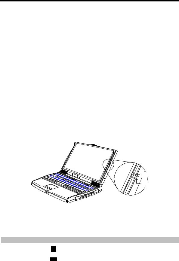
Table 1-2 |
Left Port Descriptions |
||||||
|
|
|
|
|
|
|
|
Port |
|
Icon |
Connects to... |
||||
|
|
|
|
|
|
|
|
PC Card slots |
|
|
|
|
|
|
Two type I/II PC Cards or one type III Card |
|
|
|
|
|
|
|
|
Microphone-in/ Line-in |
|
|
|
|
External microphone or line input device |
||
|
|||||||
|
|
|
|
|
|||
Speaker-out/ Line-out |
|
|
|
|
|
Amplified speakers or headphones |
|
|
|||||||
|
|
|
|
|
|
|
|
|
|
|
|
|
|
|
|
PC CARD SLOTS
The computer contains two PC card slots on the left panel that accommodate two type I/II or one type III PC card(s). Consult your dealer for available PC card options.
MULTIMEDIA PORTS
The computer provides a Mic-In/Line-in port and a Speaker-out/Line-out port on the left panel to accommodate multimedia audio devices, such as a microphone, speakers, or headphones.
1.2.3Indicator Lights
The display panel contains a power indicator light and a battery indicator light as shown in the illustration below.
Power
Indicator
Battery
Indicator
Figure 1-4 |
Indicator Lights |
|
|
Table 1-3 |
Indicator Light Descriptions |
||
|
|
|
|
Indicator Light |
Icon |
Description |
|
|
|
|
|
|
|
|
|
Power Indicator |
|
|
Lights when power is on. |
|
|
|
Flashes when the computer is in suspend-to-memory mode. |
|
|
|
|
Battery Indicator |
|
Lights when the battery pack is charging. |
|
|
|
|
Flashes when battery power is low. |
|
|
|
|
|
|
|
|
System Introduction |
1-5 |

1.2.4Hot Keys
The computer’s special Fn key, used in combination with other keys, provides “hot-key” combinations that access system control functions, such as screen contrast, brightness, volume output, and the BIOS setup utility.
|
|
|
|
|
|
|
|
|
|
Table 1-4 |
|
Hot Key Descriptions |
|
|
|
||||
|
|
|
|
|
|
|
|
|
|
Hot Key |
|
Icon |
|
Function |
Description |
|
|||
|
|
|
|
|
|
|
|
||
Fn+Esc |
|
|
|
|
Suspend-to-memory |
Enters suspend-to-memory mode |
|
||
|
|
|
|
|
|||||
|
|
|
|
|
|
|
|
||
|
|
|
|
|
|
|
|
||
Fn+F1 |
? |
|
|
Help |
Displays the hot-key list |
|
|||
|
|
|
|
|
|
|
|
||
|
|
|
|
|
|
|
|
||
Fn+F2 |
|
|
|
|
Setup |
Enters the BIOS setup utility |
|
||
|
|
|
|
|
|||||
|
|
|
|
|
|
|
|
||
|
|
|
|
|
|
|
|
||
Fn+F3 |
|
PnP |
Plug and Play |
Performs system configuration for Plug and Play operating |
|
||||
|
|
Configuration |
systems like Windows 95 |
|
|||||
|
|
|
|
|
|
||||
|
|
|
|
|
|
|
|
||
Fn+F4 |
|
|
|
|
Screen Blackout |
Blanks the screen to save power; to wake up the screen, |
|
||
|
|
|
|
|
|||||
|
|
|
|
|
|
|
press any key |
|
|
|
|
|
|
|
|
|
|
||
|
|
|
|
|
|
|
|
||
Fn+F5 |
|
|
|
|
Display Toggle |
Switches display from the built-in display, to an external |
|
||
|
|
|
|
|
|||||
|
|
|
|
|
|
|
monitor, to both built-in and external if one is connected |
|
|
|
|
|
|
|
|
|
|
||
|
|
|
|
|
|
|
|
||
Fn+F6 |
|
|
|
|
Fuel Gauge On/Off |
Toggles battery gauge display on and off. The gauge shows |
|
||
|
|
|
|
|
|||||
|
|
|
|
|
|
|
the percentage of charge left in the battery. |
|
|
|
|
|
|
|
|
|
|
||
|
|
|
|
|
|
|
Shows a plug icon if a powered AC adapter is connected to |
|
|
|
|
|
|
|
|
|
the computer; shows a speaker icon if speaker output is on |
|
|
|
|
|
|
|
|
|
(Fn+F7); shows a T icon if turbo mode is on (Fn+2) |
|
|
|
|
|
|
|
|
|
|
||
Fn+F7 |
|
|
|
|
Speaker On/Off |
Toggles speaker output on and off |
|
||
|
|
|
|
|
|||||
|
|
|
|
|
|
|
|
||
|
|
|
|
|
|
|
|
||
Fn+F8 |
|
|
|
|
Lock System |
Locks the computer and requires a password to unlock it |
|
||
|
|
|
|
|
|||||
|
|
|
|
|
Resources |
|
|
|
|
|
|
|
|
|
|
|
|
||
|
|
|
|
|
(Password Lock) |
|
|
|
|
|
|
|
|
|
|
|
|
||
Fn+F9 |
|
|
|
|
Eject |
Accesses the eject menu described on page 7 |
|
||
|
|
|
|
|
|||||
|
|
|
|
|
|
|
|
||
|
|
|
|
|
|
|
|
||
Fn+Ctrl+− |
|
|
|
|
Volume Up |
Increases speaker volume |
|
||
|
|
|
|
|
|||||
|
|
|
|
|
|
|
|
||
Fn+Ctrl+↓ |
|
|
|
|
Volume Down |
Decreases speaker volume |
|
||
|
|
|
|
|
|||||
|
|
|
|
|
|
|
|
||
Fn+Ctrl+→ |
|
|
|
|
Balance Right |
Shifts speaker balance to the right |
|
||
|
|
|
|
|
|||||
|
|
|
|
|
|
|
|
||
Fn+Ctrl+← |
|
|
|
|
Balance Left |
Shifts speaker balance to the left |
|
||
|
|
|
|
|
|||||
|
|
|
|
|
|
|
|
|
|
|
|
|
|
|
|
|
|
|
|
1-6 |
Service Guide |

Table 1-4 |
|
Hot Key Descriptions |
|
|
||
|
|
|
|
|
|
|
Hot Key |
Icon |
Function |
Description |
|
||
|
|
|
|
|
|
|
Fn+á+− |
|
|
|
Brightness Up |
Increases screen brightness |
|
|
|
|
|
|||
|
|
|
|
|
|
|
|
|
|
|
|
|
|
Fn+á+↓ |
|
|
|
Brightness Down |
Decreases screen brightness |
|
|
|
|
|
|||
|
|
|
|
|
|
|
|
|
|
|
|
|
|
Fn+á+→ |
|
|
|
Contrast Up |
Increases screen contrast (not available for TFT displays) |
|
|
|
|
|
|||
|
|
|
|
|
|
|
|
|
|
|
|
|
|
Fn+á+← |
|
|
|
Contrast Down |
Decreases screen contrast (not available for TFT displays) |
|
|
|
|
|
|||
|
|
|
|
|
|
|
|
|
|
|
|
|
|
Fn+− |
|
|
|
Fuel Gauge Up |
With the fuel gauge displayed, moves the fuel gauge up |
|
|
|
|
|
|
|
|
Fn+↓ |
|
|
|
Fuel Gauge Down |
With the fuel gauge displayed, moves the fuel gauge down |
|
|
|
|
|
|
|
|
Fn+→ |
|
|
|
Fuel Gauge Right |
With the fuel gauge displayed, moves the fuel gauge right |
|
|
|
|
|
|
|
|
Fn+← |
|
|
|
Fuel Gauge Left |
With the fuel gauge displayed, moves the fuel gauge left |
|
|
|
|
|
|
|
|
Fn+1 |
|
|
|
CD Eject |
Ejects the CD-ROM drive |
|
|
|
|
|
|
|
|
Fn+2 |
|
|
|
Turbo Mode On/Off |
Toggles turbo mode on and off |
|
|
|
|
|
|
|
|
|
|
|
|
|
|
|
EJECT MENU
The Fn+F9 hot-key combination brings up a special eject menu that allows you to perform several system configuration functions.
Eject Options: |
|
.................Battery (Suspend-to-disk) |
Change |
CD-ROM Disk (Also Fn-1) .................... |
Eject |
Mini Dock (Suspend) ........................ |
Change |
Power Off .................................. |
Change |
−↓←→ = Move Highlight Bar, = Select, ESC = Exit |
|
|
|
Table 1-5 |
Eject Menu Item Descriptions |
|
|
|
|
Select… |
|
To… |
|
|
|
Battery |
|
Store all current data and system information to the hard disk. |
(Suspend to Disk) |
|
|
|
|
|
CD-ROM Disk |
|
Open the CD-ROM drive (eject a CD). |
(Also Fn-1) |
|
|
|
|
|
Mini Dock |
|
Undock the computer. Press the dock lock and pull the dock handle toward you to |
(Suspend) |
|
undock the computer. (See the mini dock manual for details.) Once the computer is |
|
|
successfully undocked, press any key to resume. |
|
|
|
Power Off |
|
Turn the computer off. If you are using Windows 95, use the Shutdown command to |
|
|
turn off your computer. |
|
|
|
|
|
|
System Introduction |
1-7 |
1.3System Specification Overview
Table 1-6 System Specifications
Item |
Standard |
Optional |
|
|
|
Microprocessor |
Intel Pentium® II 266 MHz processor |
|
|
|
|
Memory |
|
|
System / Main |
64MB |
Expandable to 128MB using |
|
Dual 64-bit memory banks |
8/16/32/64MB soDIMMs |
External cache |
512KB L2 cache (synchronous SRAM) |
|
|
|
|
Flash BIOS |
256KB |
|
|
|
|
Storage system |
One 2.5-inch, high-capacity Enhanced-IDE |
Higher-capacity E-IDE hard disk |
|
hard disk |
Second optional hard disk drive module |
|
|
|
|
One high-speed IDE CD-ROM drive module |
(3-inch) |
|
One 3.5-inch, 1.44MB floppy drive module |
|
|
(internal/external use) |
|
|
|
|
Display |
Active-matrix TFT LCD |
Up to 1024x768, 256-color ultra-VGA |
|
13.3-inch, 1024x768, 64K colors (XGA) |
monitor |
|
|
LCD projection panel |
|
|
|
Video system |
PCI local bus video with 128-bit graphics |
|
|
accelerator |
|
|
|
|
Audio system |
16-bit stereo audio with built-in FM |
|
|
synthesizer |
|
|
Built-in microphone and dual angled |
|
|
speakers |
|
|
|
|
Communications |
|
PC card modem |
system |
|
|
|
|
|
Operating |
Windows 95, 98 |
|
system |
|
|
|
|
|
Keyboard and |
84-/85-key with Win95 keys; |
101-/102-key, PS/2-compatible |
pointing device |
auto-tilt feature |
keyboard or 17-key numeric keypad |
|
Touchpad (centrally-located on palm rest) |
External serial or PS/2 mouse or similar |
|
|
pointing device |
|
|
|
I/O ports |
One 9-pin RS-232 serial port |
Serial mouse, printer or other serial |
|
(UART16550-compatible) |
devices |
|
One 25-pin parallel port |
Parallel printer or other parallel devices; |
|
(EPP/ECP-compliant) |
floppy drive module (when used |
|
|
externally) |
|
One 15-pin CRT port |
Up to a 1024x768 ultra-VGA monitor |
|
One 6-pin PS/2 connector |
17-key numeric keypad, PS/2 |
|
|
keyboard, mouse or trackball |
|
One 240-pin mini dock connector |
Mini dock |
I/O Ports |
One type III or two type II PC Card slot(s) |
LAN card or other PC cards |
(continued) |
|
|
|
|
|
|
|
|
1-8 |
Service Guide |

Table 1-6 |
System Specifications |
|
|
|
|
|
|
Item |
|
Standard |
Optional |
|
|
|
|
|
|
One fast infrared port (IrDA-compliant) |
External IR adapter |
|
|
One 3.5mm minijack microphone-in/line-in |
Microphone or line-in device |
|
|
jack |
|
|
|
One 3.5mm minijack speaker-out/line-out |
Speakers or headphones |
|
|
jack |
|
|
|
One USB port |
USB device |
|
|
|
|
Weight |
|
(includes battery) |
|
with FDD |
|
3.5 kg. (7.5 lbs.) |
|
with CD-ROM |
|
3.8 kg. (7.8 lbs.) |
|
|
|
|
|
Dimensions |
|
L x W x H |
Carrying bag |
Round contour |
|
309x245x56mm |
|
Main footprint |
|
12.2” x 9.6” x 2.2” |
|
|
|
|
|
Temperature |
|
|
|
Operating |
|
10ºC ~ 35ºC(50ºF ~ 95ºF) |
|
Non-operating |
|
-10ºC ~ 60ºC(14ºF ~ 140ºF) |
|
|
|
|
|
Humidity |
|
(non-condensing) |
|
Operating |
|
20% ~ 80% RH |
|
Non-operating |
|
20% ~ 80% RH |
|
|
|
|
|
AC adapter |
|
100~240Vac, 50~60Hz autosensing AC |
Extra AC adapter |
|
|
adapter |
|
|
|
|
|
Battery pack |
|
|
Extra battery pack |
Type |
|
57WH Lithium-Ion battery with intelligent |
|
|
|
charging and built-in battery gauge |
|
Charge time |
|
2.0-hour rapid-charge |
|
|
|
4.0-hour in-use charge |
|
|
|
|
|
|
|
|
|
System Introduction |
1-9 |

1.4Board Layout
1-10 |
Service Guide |
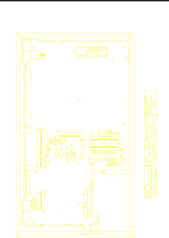
1.4.1System Board (Top Side)
Figure 1-5 System Board (Top Side)
System Introduction |
1-11 |

1.4.2System Board (Bottom Side)
Figure 1-6 System Board (Bottom Side)
1-12 |
Service Guide |
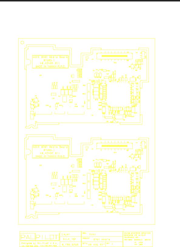
1.4.3Media Board (Top Side)
Figure 1-7 Media Board (Top Side)
System Introduction |
1-13 |
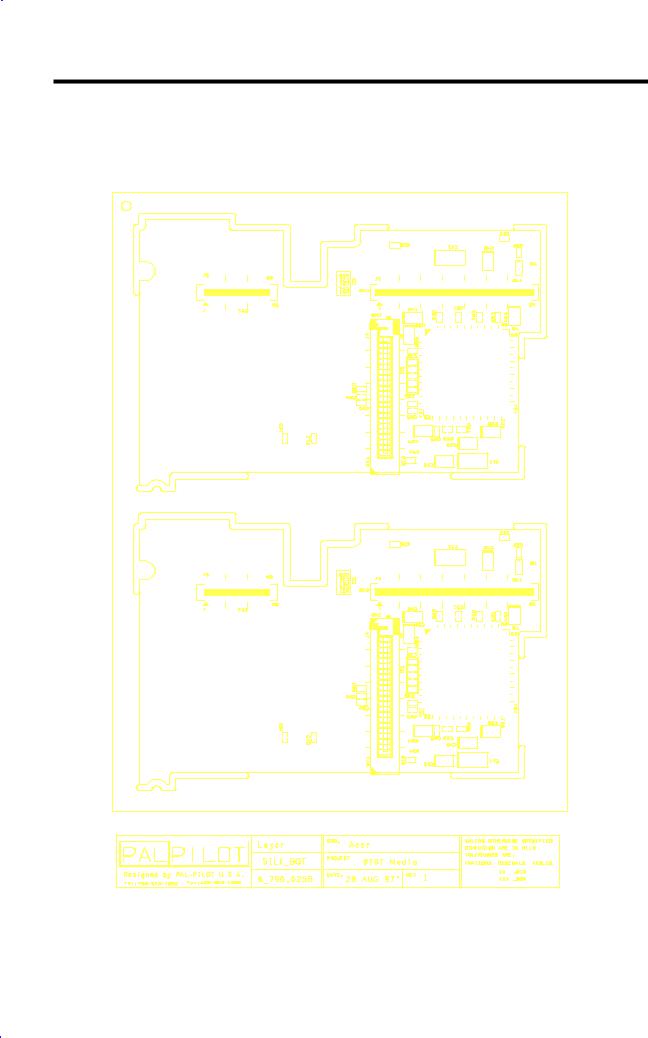
1.4.4Media Board (Bottom Side)
Figure 1-8 Media Board (Bottom Side)
1-14 |
Service Guide |
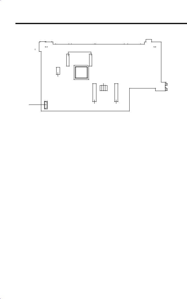
1.5Jumpers and Connectors
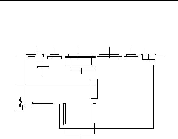
1.5.1Mainboard
CN1 |
CN2 |
CN3 |
CN4 |
CN5 |
CN6 |
CN7
U1
CN9
CN8
CN10
CN11 
CN12
CN13 CN14, CN15
CN1 |
USB |
CN8, CN9 |
Multimedia board connector |
CN2 |
VGA port |
CN10 |
FDD/CD-ROM connector |
CN3 |
Mini dock port |
CN14, CN15 |
CPU board connector |
CN4 |
Parallel port |
CN13 |
Hard disk drive connector |
CN5 |
Serial Port |
CN12 |
Speaker-out/Line-out Jack |
CN6 |
PS2 mouse/keyboard port |
CN11 |
Microphone-in/Line-in Jack |
CN7 |
AC adapter plug-in port |
U1 |
SIR/FIR infrared LED |
Figure 1-9 Mainboard Jumpers and Connectors (Top Side)
System Introduction |
1-15 |
CN19, CN18
SW1 |
|
|
|
|
|
|
|
|
|
|
|
|
|
|
|
|
|
|
|
|
|
|
|
|
|
|
|
|
|
|
|
|
|
|
|
|
|
|
|
CN16 |
|
|
|
|
|
|
|
|
|
|
|
|
|
|
|
|
|
|
|
|
|
|
|
|
|
|
|
|
|
|
|
|
|
|
|
|
|
|
|
||
|
|
|
|
|
|
|
|
|
|
|
|
|
|
|
|
|
|
|
|
|
|
|
|
|
|
|
|
|
|
|
|
|
|
|
|
|
|
|
||
|
|
|
|
|
|
|
|
|
|
|
|
|
|
|
|
|
|
|
|
|
|
|
|
|
|
|
|
|
|
|
|
|
|
|
|
|
|
|
|
|
CN17
CN20
SW2
 ON
ON
OFF
1 4
CN22 |
SI2 |
SI1 |
CN20, CN19 |
DC-DC converter connector |
CN22 |
Battery connector |
CN17 |
Left speaker connector |
CN16 |
Right speaker connector |
CN20 |
Debug port |
SW1 |
Reset Switch |
|
|
SW2 |
Jumper Setting |
Figure 1-10 Mainboard Jumpers and Connectors (Bottom Side)
The following table shows the settings of the mainboard’s bottom side jumper pads.
Table 1-7 Mainboard Jumpers Pads Settings (Bottom Side)
Jumper Pad |
Descriptions |
Settings |
|
|
|
SW2(1) |
Keyboard type selection |
OFF: Other keyboard |
|
|
ON: Japan keyboard |
|
|
|
SW2(2) |
Password settings |
OFF: Enable password |
|
|
ON: Bypass password |
|
|
|
SW2(3) |
BIOS type selection |
OFF: Acer BIOS |
|
|
ON: OEM BIOS |
|
|
|
SW2(4) |
Reserved |
|
|
|
|
|
|
|
1-16 |
Service Guide |
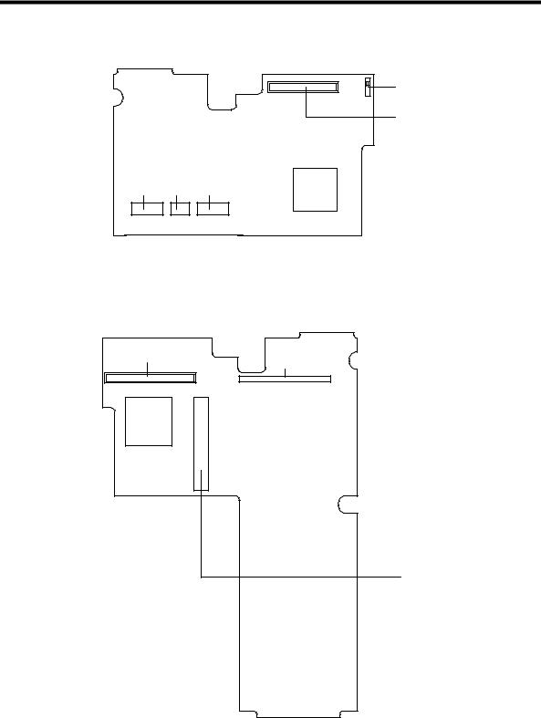
1.5.2Media Board
CN2
CN1
CN4 CN5 CN6
CN2 |
Lid switch |
CN6 |
Touchpad connector |
CN1 |
LCD connector |
CN4, CN5 |
Keyboard connector |
Figure 1-11 Media Board Jumpers and Connectors (Top Side)
CN7
CN8
CN9
CN7, CN8 |
Mainboard connector |
CN9 |
PCMCIA socket connector |
Figure 1-12 Media Board Jumpers and Connectors (Bottom Side)
System Introduction |
1-17 |
 Loading...