


Acer TravelMate 240/250 Series
Service Guide
SERVICE CD PART NO.: VD.T30V1.001
PRINTED IN TAIWAN

Revision History
Please refer to the table below for the updates made on HP Lapin service guide.
Date |
Chapter |
Updates |
|
|
|
|
|
|
|
|
|
|
|
|
|
|
|
|
|
|
|
|
|
II

Copyright
Copyright © 2003 by Acer Incorporated. All rights reserved. No part of this publication may be reproduced, transmitted, transcribed, stored in a retrieval system, or translated into any language or computer language, in any form or by any means, electronic, mechanical, magnetic, optical, chemical, manual or otherwise, without the prior written permission of Acer Incorporated.
Disclaimer
The information in this guide is subject to change without notice.
Acer Incorporated makes no representations or warranties, either expressed or implied, with respect to the contents hereof and specifically disclaims any warranties of merchantability or fitness for any particular purpose. Any Acer Incorporated software described in this manual is sold or licensed "as is". Should the programs prove defective following their purchase, the buyer (and not Acer Incorporated, its distributor, or its dealer) assumes the entire cost of all necessary servicing, repair, and any incidental or consequential damages resulting from any defect in the software.
Intel is a registered trademark of Intel Corporation.
Pentium and Pentium II/III are trademarks of Intel Corporation.
Other brand and product names are trademarks and/or registered trademarks of their respective holders.
III

Conventions
The following conventions are used in this manual:
Screen messages |
Denotes actual messages that appear |
|
on screen. |
|
|
NOTE |
Gives bits and pieces of additional |
|
information related to the current |
|
topic. |
|
|
WARNING |
Alerts you to any damage that might |
|
result from doing or not doing specific |
|
actions. |
|
|
CAUTION |
Gives precautionary measures to |
|
avoid possible hardware or software |
|
problems. |
|
|
IMPORTANT |
Reminds you to do specific actions |
|
relevant to the accomplishment of |
|
procedures. |
|
|
IV

Preface
Before using this information and the product it supports, please read the following general information.
1.This Service Guide provides you with all technical information relating to the BASIC CONFIGURATION decided for Acer "global" product offering. To better fit local market requirements and enhance product competitiveness, your regional office MAY have decided to extend the functionality of a machine (e.g. add-on card, modem, or extra memory capability). These LOCALIZED FEATURES will NOT be covered in this generic service guide. In such cases, please contact your regional offices or the responsible personnel/channel to provide you with further technical details.
2.Please note WHEN ORDERING FRU PARTS, that you should check the most up-to-date information available on your regional web or channel. If, for whatever reason, a part number change is made, it will not be noted in the printed Service Guide. For ACER AUTHORIZED SERVICE PROVIDERS, your Acer office may have a DIFFERENT part number code to those given in the FRU list of this printed Service Guide. You MUST use the list provided by your regional Acer office to order FRU parts for repair and service of customer machines.
V

VI

Table of Contents
Chapter 1 |
System Introduction |
1 |
Features . . . . . . . . . . . . . . . . . . . . . . . . . . . . . . . . . . . . . . . . . . . . . . . . . . . . . . . .1
System Block Diagram . . . . . . . . . . . . . . . . . . . . . . . . . . . . . . . . . . . . . . . . . . . . .3
Board Layout . . . . . . . . . . . . . . . . . . . . . . . . . . . . . . . . . . . . . . . . . . . . . . . . . . . .4
Panel . . . . . . . . . . . . . . . . . . . . . . . . . . . . . . . . . . . . . . . . . . . . . . . . . . . . . . . . . . .6
Indicators . . . . . . . . . . . . . . . . . . . . . . . . . . . . . . . . . . . . . . . . . . . . . . . . . . . . . .12
Keyboard . . . . . . . . . . . . . . . . . . . . . . . . . . . . . . . . . . . . . . . . . . . . . . . . . . . . . .14
Hot Keys . . . . . . . . . . . . . . . . . . . . . . . . . . . . . . . . . . . . . . . . . . . . . . . . . . . . . . .16
Hardware Specifications and Configurations . . . . . . . . . . . . . . . . . . . . . . . . . . .19
Chapter 2 |
System Utilities |
34 |
BIOS Setup Utility . . . . . . . . . . . . . . . . . . . . . . . . . . . . . . . . . . . . . . . . . . . . . . . |
.34 |
|
BIOS Flash Utility . . . . . . . . . . . . . . . . . . . . . . . . . . . . . . . . . . . . . . . . . . . . . . . |
.46 |
|
System Diagnostic Diskette . . . . . . . . . . . . . . . . . . . . . . . . . . . . . . . . . . . . . . . . |
46 |
|
Chapter 3 |
Machine Disassembly and Replacement |
48 |
General Information . . . . . . . . . . . . . . . . . . . . . . . . . . . . . . . . . . . . . . . . . . . . . .49
Disassembly Procedure Flowchart . . . . . . . . . . . . . . . . . . . . . . . . . . . . . . . . . . .50
Removing the Battery . . . . . . . . . . . . . . . . . . . . . . . . . . . . . . . . . . . . . . . . . . . . .52
Removing the Memory Module . . . . . . . . . . . . . . . . . . . . . . . . . . . . . . . . . . . . . .53
Removing the Modem Board . . . . . . . . . . . . . . . . . . . . . . . . . . . . . . . . . . . . . . .54
Removing the Hard Disk Drive Module . . . . . . . . . . . . . . . . . . . . . . . . . . . . . . . .55
Removing the LCD Module . . . . . . . . . . . . . . . . . . . . . . . . . . . . . . . . . . . . . . . . .56
Disassembling the LCD Module . . . . . . . . . . . . . . . . . . . . . . . . . . . . . . . . . . . . .59
Disassembling the Main Unit . . . . . . . . . . . . . . . . . . . . . . . . . . . . . . . . . . . . . . .63
System Upgrade Procedure . . . . . . . . . . . . . . . . . . . . . . . . . . . . . . . . . . . . . . . .73
Machine Disassembly and Replacement 74
Assembling the Main Unit . . . . . . . . . . . . . . . . . . . . . . . . . . . . . . . . . . . . . . . . . .74
Assembling the LCD Module . . . . . . . . . . . . . . . . . . . . . . . . . . . . . . . . . . . . . . .83
Installing the LCD Module . . . . . . . . . . . . . . . . . . . . . . . . . . . . . . . . . . . . . . . . . .87
Installing the Hard Disk Drive Module . . . . . . . . . . . . . . . . . . . . . . . . . . . . . . . . .90
Removing the Modem Board . . . . . . . . . . . . . . . . . . . . . . . . . . . . . . . . . . . . . . .91
Installing the Memory Module . . . . . . . . . . . . . . . . . . . . . . . . . . . . . . . . . . . . . . .92
Installing the Battery . . . . . . . . . . . . . . . . . . . . . . . . . . . . . . . . . . . . . . . . . . . . . .93
Chapter 4 |
Troubleshooting |
94 |
System Check Procedures . . . . . . . . . . . . . . . . . . . . . . . . . . . . . . . . . . . . . . . . .95
Power-On Self-Test (POST) Error Message . . . . . . . . . . . . . . . . . . . . . . . . . . .99
Index of Error Messages . . . . . . . . . . . . . . . . . . . . . . . . . . . . . . . . . . . . . . . . . .100
Index of Symptom-to-FRU Error Message . . . . . . . . . . . . . . . . . . . . . . . . . . . .103
Intermittent Problems . . . . . . . . . . . . . . . . . . . . . . . . . . . . . . . . . . . . . . . . . . . .106
Undetermined Problems . . . . . . . . . . . . . . . . . . . . . . . . . . . . . . . . . . . . . . . . . .107
Chapter 5 |
Jumper and Connector Locations |
108 |
Chapter 6 |
FRU (Field Replaceable Unit) List |
112 |
TravelMate 240/250 Exploded Diagram . . . . . . . . . . . . . . . . . . . . . . . . . . . . . .113
Appendix A Model Definition and Configuration 126
Model Name Definition . . . . . . . . . . . . . . . . . . . . . . . . . . . . . . . . . . . . . . . . . . .126
Appendix B Test Compatible Components 128
Microsoft Windows XP Environment Test . . . . . . . . . . . . . . . . . . . . . . . . . . . . .129
VII

Table of Contents
Microsoft Windows 2000 Environment Test . . . . . . . . . . . . . . . . . . . . . . . . . . .133
Microsoft Windows 98 Environment Test . . . . . . . . . . . . . . . . . . . . . . . . . . . . .137
Appendix C Online Support Information |
142 |
Index |
144 |
VIII

Table of Contents
IX

Chapter 1
System Introduction
Features
This computer was designed with the user in mind. Here are just a few of its many features:
Performance
Intel® Mobile Pentium® 4 series processors with 512 KB L2 cache or Intel® Mobile Celeron® processor with 256 KB L2 cache 64-bit memory bus
64-bit memory bus
CD, DVD or DVD/CD-RW combo drive. Built-in floppy diskette drive High-capacity, Enhanced-IDE hard disk High-capacity battery pack
Advanced Configuration Power Interface (ACPI) power management system
Multimedia
16-bit high-fidelity AC’97 stereo audio with 3D sound and wavetable synthesizer Built-in dual speakers
Highspeed CD, DVD, or DVD/CD-RW combo drive
Connectivity
High-speed fax/data modem port Ethernet/Fast Ethernet port
USB (Universal Serial Bus) 2.0 ports 802.11a+g/802.11b wireless LAN option Bluetooth option
Multimedia
All-in-one design (CD-ROM, floppy disk drive, hard disk drive)
Sleek, smooth and stylish design
Full-sized keyboard
Ergonomically centered touchpad pointing device with Internet scroll key
Expansion
Two type II CardBus PC Card slots/ One Type III CardBus PC card slot
Upgrageable memory
I/O Ports
One VGA port (external CRT)
One DC-in port (AC adapter)
One microphone/line-in port
One line-out port
Two CardBus type II slot (3.3V and 5V support)
Chapter 1 |
1 |
Four USB ports (USB 2.0 compliant
One RJ-11 port
Onc RJ-45 jack
One parallel port
One FIR
Display
14.1” or 15” Thin-Film Transistor (TFT) liquid crystal display (LCD) displaying 16M color at 1024x768 XGA (eXtended Graphics Array) resolution
3D capabilities
Simultaneous LCD and CRT display support
Supports other output display devices such as LCD projection panels for large audience presentations
Dual display capacity
2 |
TravelMate 240/ 250 |

System Block Diagram
|
|
|
|
|
|
|
|
|
|
|
|
|
Mobile CPU |
|
|
|
|
|
|
|
CLK GEN. |
|
|
|
|
||||||
|
|
|
|
|
|
|
|
Portability |
|
||||||
|
|
|
|
CY 28346 |
|
|
|
Mobile P4 |
|
||||||
|
|
|
|
|
|
|
|
3 |
|
|
|
|
4, 5 |
|
|
|
|
|
|
|
|
|
|
|
|
|
|
|
HOST BUS |
133MHz |
|
|
|
|
|
|
|
|
|
|
|
|
|
|
|
|
|
|
|
|
DDR*2 |
266/333MHz |
|
GMCH |
|||||||||
|
|
|
333MHz |
|
|||||||||||
|
|
|
|
|
|
|
|
|
|
|
|
||||
|
|
|
9,10 |
|
|
|
|
|
|
|
Montara-GT |
||||
|
|
|
|
|
|
|
|
|
|
|
|
|
|
6,7,8 |
|
|
|
|
|
|
|
|
|
|
|
|
|
|
|
|
|
|
|
|
|
|
|
|
|
|
|
|
|
|
HUB I/F |
66MHz |
|
|
|
|
|
|
|
|
|
|
|
|
|
|
|
||
|
|
|
|
|
|
|
|
|
|
|
|
|
|
||
Line In |
|
|
AC'97 |
|
|
|
|
|
|
|
|||||
Mic In |
|
|
|
|
AC-Link |
|
|
|
|
||||||
23 |
|
|
CODEC |
|
|
|
|
|
|||||||
|
|
|
|
|
|
|
|
|
|
|
|
||||
|
|
|
|
|
CS4299XQ |
|
|
|
|
|
|
|
|||
|
|
|
|
|
|
|
|
22 |
|
|
|
|
|
|
|
|
|
|
|
|
|
|
|
|
|
|
|
|
|
|
|
ICH4-M
|
|
|
|
OP AMP |
|
|
|
|
|
|
|
|
|
|
|
|
Line Out |
|
|
|
|
|
|
|
|
|
|
|
|
|
|
|
|
|
|
|
G1421 |
|
|
|
|
|
|
|
|
|
|
|
|
|
23 |
|
|
|
|
|
|
|
|
|
|
|
|
|
|
|
|
|
|
|
|
23 |
|
|
|
|
|
|
13,14,15 |
|||||
|
|
|
|
|
|
|
|
|
|
|
||||||
|
|
|
|
|
|
|
|
|
|
|
||||||
|
|
|
|
|
|
|
|
|
|
|
||||||
|
|
|
|
MODEM+BT |
|
|
|
|
|
|
|
|
|
|
|
|
INT.SPKR |
|
|
|
MDC CARD |
|
|
|
PIDE |
SIDE |
|
|
|
|
|
||
|
|
|
|
|
|
|||||||||||
23 |
|
18 |
|
|
|
|
|
|
|
|
|
|
|
|
||
|
|
|
|
|
|
|
|
|
|
|
CD ROM |
|
|
|
|
|
|
|
|
|
|
|
HDD |
|
USB |
|
|||||||
|
|
|
|
|
|
|
|
17 |
|
|
||||||
|
|
|
|
|
|
17 |
|
|
|
|
4 PORT18 |
|
||||
G768D |
|
|
|
|
CRT |
||
|
|
|
|
16 |
|
|
CONN 12 |
|
|
|
RGB
LVDS LCD
XGA/SXGA+
11
PCI BUS |
CARDBUS |
|
|
|
CARDBUS |
|
|
|
|
||||
|
|
|
||||
PCI 1520 |
|
|
PWR SW |
|
TWO SLOT |
|
|
|
|
|
|||
|
GHK |
|
|
TPS2224A |
|
|
|
|
|
|
|
||
|
25/B/1 |
26 |
|
27 |
|
27 |
|
|
|
|
|
||
|
|
|
|
|
|
|
LAN |
|
|
|
|
|
|
|
|
|
|
|
|
|
|
|
|
||
|
|
|
|
|
|
|
RTL 8101L |
|
|
|
|
|
|
|
|
|
|
|
|
||||||
|
|
|
|
|
|
21/D/4 |
19,20 |
|
|
|
|
Mini-PCI |
|
|
|
||||||||||
|
|
|
|
|
|
|
|
|
|
|
|
|
|
|
|
|
|
|
|||||||
|
|
|
|
|
|
|
|
|
|
|
|
|
|
|
|
802.11A/B/G |
|
|
|
||||||
|
|
|
|
|
|
|
|
|
|
|
|
|
|
|
|
|
|
21 |
|
|
|
||||
LPC BUS |
|
|
|
|
|
|
|
|
|
|
|
|
|
|
|
|
|||||||||
|
|
|
|
|
|
|
|
|
|
|
|
|
|
|
|
|
|
|
|
|
|
|
|
|
|
|
|
|
|
NS SIO |
|
|
KBC |
|
|
|
FWH |
|
|
LPC |
|||||||||||
|
|
|
|
|
|
M38857 |
|
|
|
4MB |
|
|
DEBUG |
||||||||||||
|
|
|
|
PC87392 |
|
|
|
|
|
|
|
||||||||||||||
|
|
|
|
|
|
|
|
|
|
|
|
|
|
PLCC32 |
|
|
CONN. |
||||||||
|
|
|
|
|
|
|
|
|
|
|
|
|
|
|
|
|
|
|
|
||||||
|
|
|
|
28 |
|
|
25 |
|
|
SOIC4024 |
|
24 |
|||||||||||||
|
|
|
|
|
|
|
|
|
|
|
|
|
|
|
|
|
|
|
|
|
|
|
|
|
|
|
|
|
|
|
|
|
|
|
|
|
|
|
|
|
|
|
|
|
|
|
|
|
|
|
|
|
|
PRN |
|
|
|
FIR |
|
|
|
|
Touch |
|
|
|
INT KB |
|
|||||||||
|
|
Port |
|
|
|
|
|
|
|
|
Pad |
|
|
|
|
|
|
||||||||
|
29 |
|
|
|
28 |
|
|
|
|
|
|
|
|
|
|
25 |
|
|
|
|
25 |
|
|||
Chapter 1 |
3 |
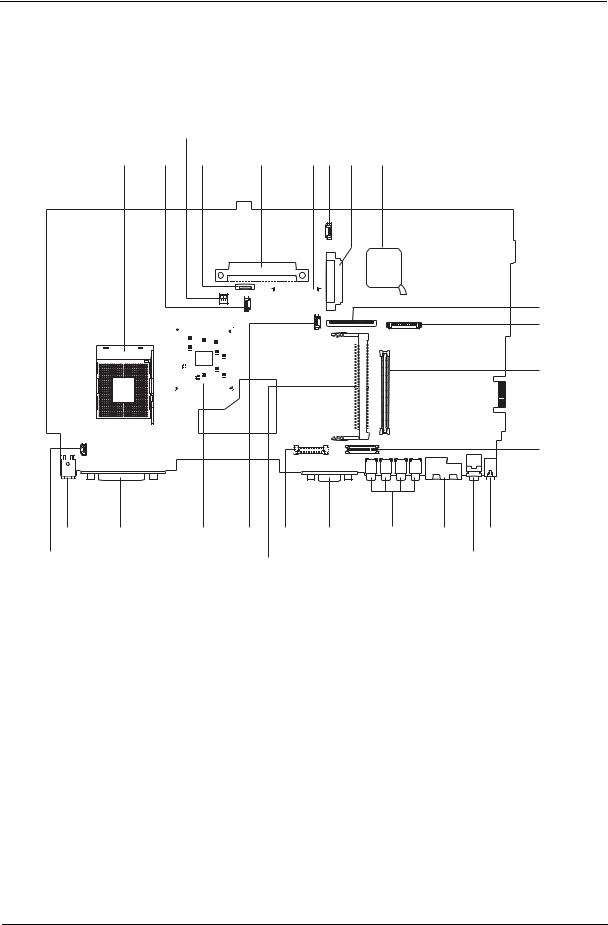
Board Layout
Top View
3
1 |
2 |
4 |
|
|
|
|
5 |
|
6 7 8 |
9 |
|||||||||||||||||||
|
|
|
|
|
|
|
|
|
|
|
|
|
|
|
|
|
|
|
|
|
|
|
|
|
|
|
|
|
|
|
|
|
|
|
|
|
|
|
|
|
|
|
|
|
|
|
|
|
|
|
|
|
|
|
|
|
|
|
|
|
|
|
|
|
|
|
|
|
|
|
|
|
|
|
|
|
|
|
|
|
|
|
|
|
|
|
|
|
|
|
|
|
|
|
|
|
|
|
|
|
|
|
|
|
|
|
|
|
|
|
|
|
|
|
|
|
|
|
|
10
11
12
13
|
|
|
|
|
|
|
|
|
|
|
|
|
|
|
|
|
|
|
|
|
|
|
|
|
|
|
|
|
|
|
|
|
|
|
|
|
|
|
|
|
|
|
|
|
|
|
|
|
|
|
|
|
|
|
|
|
|
|
|
|
|
|
|
|
|
|
|
|
|
|
|
|
|
|
|
23 |
|
|
|
|
|
|
|
|
|
|
|
|
|
|
|
|
|
|
|
24 |
22 |
21 19 |
|
18 |
17 |
16 |
14 |
||||||||||||||||
25 |
|
|
|
|
|
|
|
20 |
|
|
|
|
|
|
|
|
|
|
|
15 |
|
|
|
|
|
|
|
|
|
|
|
|
|
|
|
|
|
|
|
|
|
|
|
|
|
|
|
1 |
CPU Socket |
14 |
Line-in Port |
2 |
Fan Connector |
15 |
Line-out Port |
3 |
SW1 (Please see Chapter 5 for detailed settings) |
16 |
RJ45+RJ11 |
4 |
Touchpad Cable Connector |
17 |
Four USB Ports |
5 |
HDD Connector |
18 |
VGA Port |
6 |
Keyboard Connector |
19 |
LCD Coaxial Cable Connector |
7 |
Speaker Cable Connector |
20 |
Mini PCI Connector |
8 |
Optical Drive Connector |
21 |
RTC Battery Connector |
9 |
South Bridge |
22 |
North Bridge |
10 |
FDD Connector |
23 |
Parallel Port |
11 |
Launch Cable Connector |
24 |
DC-in Port |
|
PCMCIA Slot |
25 |
LCD Lid Switch |
12 |
|||
13 |
LCD Inverter Cable Connector |
|
|
|
|
|
|
4 |
TravelMate 240/ 250 |
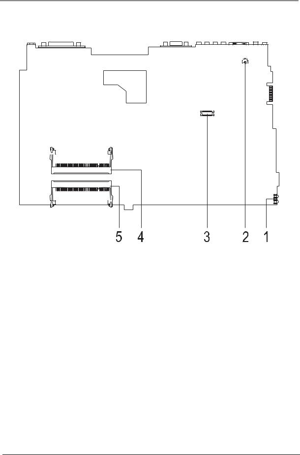
Bottom View
1FIR Port
2Modem Cable Connector
3Modem Card Connector
4DIMM Socket 2
5DIMM Socket 1
Chapter 1 |
5 |
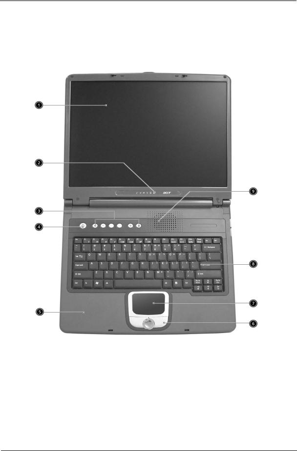
Panel
Ports allow you to connect peripheral devices to your computer as you would with a desktop PC.
Front Panel
6 |
TravelMate 240/ 250 |
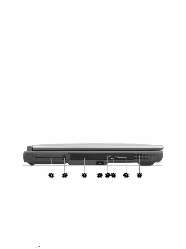
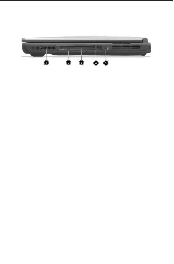
Left Panel
# |
Item |
Description |
|
|
|
1 |
Display screen |
Also called LCD (Liquid Crystal Display), displays computer |
|
|
output. |
|
|
|
2 |
Status indicators |
LEDs (Light Emitting Diodes) that turn on and off to show |
|
|
the status of the computer and its functions and |
|
|
components. |
|
|
|
3 |
Launch Keys |
Buttons for launching frequently used programs. See |
|
|
“Launch keys” on page 17 for more details. |
|
|
|
4 |
Power switch |
Turns on the computer power. |
|
|
|
5 |
Palmrest |
Comfortable support area for your hands when you use the |
|
|
computer. |
|
|
|
6 |
Click buttons (left, center and right) |
The left and right buttons function like the left and right |
|
|
mouse buttons, the center button serves as a scroll up/ |
|
|
down button. |
|
|
|
7 |
Touchpad |
Touch-sensitive pointing device which functions like a |
|
|
computer mouse. |
|
|
|
8 |
Keyboard |
Inputs data into your computer. |
|
|
|
9 |
Ventilation Slot |
Enables the computer to stay cool, even after the |
|
|
prolonged use. |
|
|
|
|
# |
|
Icon |
Item/ Port |
Description |
|
|||
|
|
|
|
|
|
|
|
|
|
|
1 |
|
|
|
|
|
PCMCIA (PC card) Port |
Connects to one Type III 16-bit PC card or 32-bit |
|
|
|
|
|
|
|
|
|
CardBus PC Card. |
|
|
|
|
|
|
|
|
|
|
|
|
2 |
|
|
|
|
|
Eject button |
Eject PC cards from the card slots. |
|
|
|
|
|
|
|
|
|
|
|
|
3 |
|
|
|
|
|
Optical drive |
Internal optical drive; accepts CDs or DVDs |
|
|
|
|
|
|
|
|
|
depending on the optical drive type. |
|
|
|
|
|
|
|
|
|
|
|
|
4 |
|
|
|
|
|
Infrared port |
Interfaces with infrared devices (e.g., infrared |
|
|
|
|
|
|
|
|
|
printer, IR-aware computer). |
|
|
|
|
|
|
|
|
|
|
|
|
|
|
|
|
|
|
|
|
|
|
5 |
|
|
|
|
|
LED indicator |
Lights up when the optical drive is active. |
|
|
|
|
|
|
|
|
|
|
|
|
6 |
|
|
|
|
|
Emergency eject slot |
Ejects the optical drive tray when the computer is |
|
|
|
|
|
|
|
|
|
turned off. There is a mechancial eject button on |
|
|
|
|
|
|
|
|
|
the CD-ROM or DVD-ROM drive. Simply insert |
|
|
|
|
|
|
|
|
|
the tip of a pen or paperclip and push to eject the |
|
|
|
|
|
|
|
|
|
tray. |
|
|
|
|
|
|
|
|
|
|
|
|
|
|
|
|
|
|
|
|
|
Chapter 1 |
7 |

# |
Icon |
Item/ Port |
Description |
|
|
|
|
7 |
|
Eject button |
Ejects the optical drive tray from the drive. |
|
|
|
|
8 |
|
Speaker |
Delivers stereo audio output. |
|
|
|
|
8 |
TravelMate 240/ 250 |
Right Panel
# |
Icon |
Item/ Port |
Description |
|
|
|
|
1 |
|
Speaker |
Delivers stereo audio output. |
|
|
|
|
2 |
|
Floppy activity indicator |
LED (light-emitting diode) that turns on and off |
|
|
|
when the floppy is active. |
|
|
|
|
3 |
|
Floppy drive |
Internal diskette drive; accepts 3.5-inch |
|
|
|
diskettes. |
|
|
|
|
4 |
|
Floppy disk eject button |
Push this button to eject the floppy disk. |
|
|
|
|
5 |
|
Security keylock |
Connects to a Kensington-compatible |
|
|
|
computer security lock. |
|
|
|
|
Chapter 1 |
9 |
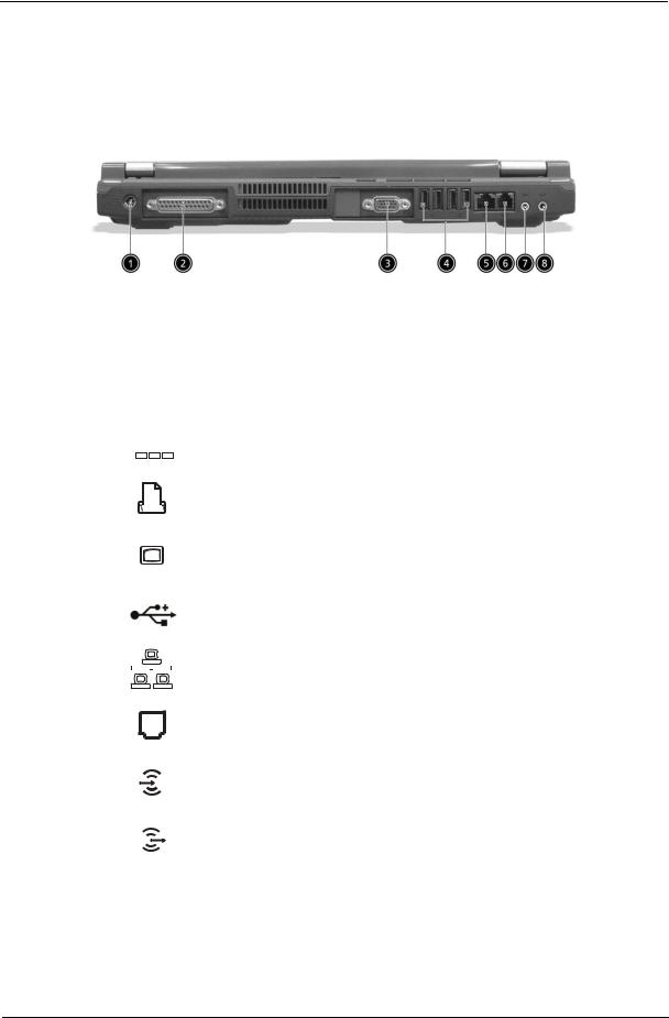
Rear Panel
l
# |
|
|
Icon |
Port |
Description |
|||
|
|
|
|
|
|
|
|
|
1 |
|
|
|
|
|
|
Power Jack |
Connects to an AC adapter |
|
|
|
|
|
|
|
|
|
|
|
|
|
|
|
|
|
|
|
|
|
|
|
|
|
|
|
|
|
|
|
|
|
|
|
|
|
|
|
|
|
|
|
|
|
2 |
|
|
|
|
|
|
Parallel port |
Connects to a parallel device (e.g., parallel |
|
|
|
|
|
|
|
|
printer) |
|
|
|
|
|
|
|
|
|
|
|
|
|
|
|
|
|
|
|
|
|
|
|
|
|
|
|
|
|
|
|
|
|
|
|
|
|
|
|
|
|
|
|
|
|
3 |
|
|
|
|
|
|
External display port |
Connects to a display device (e.g., external |
|
|
|
|
|
|
|
|
monitor, LCD projector) and displays up to |
|
|
|
|
|
|
|
|
16M colors at 1024x768 resolution |
|
|
|
|
|
|
|
|
|
4 |
|
|
|
|
|
|
USB port (four) |
Connects to any Universal Serial Bus |
|
|
|
|
|
|
|
|
devices(e.g., USB mouse, USB camera). |
|
|
|
|
|
|
|
|
|
5 |
|
|
|
|
|
|
Network jack |
Connects to an Ethernet 10/100-based |
|
|
|
|
|
|
|
|
network |
|
|
|
|
|
|
|
|
|
|
|
|
|
|
|
|
|
|
6 |
|
|
|
|
|
|
Modem jack |
Connects to the phone line |
|
|
|
|
|
|
|
|
|
7 |
|
|
|
|
|
|
Line-in jack |
Accepts audio line-in devices (e.g., audio |
|
|
|
|
|
|
|
|
CD player, stereo walkman). |
|
|
|
|
|
|
|
|
|
8 |
|
|
|
|
|
|
Speaker/Headphone- |
Connects to audio line-out devices (e.g., |
|
|
|
|
|
|
|
out jack |
speakers, headphones). |
|
|
|
|
|
|
|
|
|
10 |
TravelMate 240/ 250 |
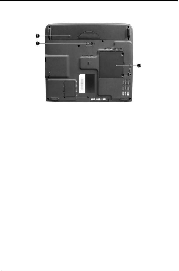
Bottom Panel
# |
Item |
Description |
|
|
|
1 |
Battery bay |
Houses the computer’s battery pack. |
|
|
|
2 |
Battery release latch |
Unlatches the battery to remove the battery pack. |
|
|
|
3 |
Memory compartment |
Houses the computer’s main memory. |
|
|
|
Chapter 1 |
11 |
Indicators
The computer has six easy-to-read status icons on the right of the display screen.
.
The Power and Standby status icons are visible even when you close the display cover so you can see the status of the computer while the cover is closed.
# |
Icon |
Function |
Description |
||||
|
|
|
|
|
|
|
|
1 |
|
|
|
|
|
Power |
Lights when the computer is on. |
|
|
|
|
|
|
|
|
2 |
|
|
|
|
|
Sleep |
Lights when the computer enters Standby |
|
|
|
|
|
|
|
mode and blinks when it enters into or |
|
|
|
|
|
|
|
resumes from hibernation mode. |
|
|
|
|
|
|
|
|
3 |
|
|
|
|
|
Media Activity |
Lights when the floppy drive, hard disk or |
|
|
|
|
|
|
|
optical drive is active. |
|
|
|
|
|
|
|
|
4 |
|
|
|
|
|
Battery Charge |
Lights when the battery is being charged. |
|
|
|
|
|
|
|
|
|
|
|
|
|
|
|
|
5 |
|
|
|
|
|
Caps Lock |
Lights when Caps Lock is activated. |
|
|
|
|
|
|
|
|
|
|
|
|
|
|
|
|
|
|
|
|
|
|
|
|
6 |
|
|
|
|
|
Num Lock |
Lights when Numeric Lock is activated. |
|
|
|
|
|
|
(Fn-F11) |
|
|
|
|
|
|
|
|
|
12 |
TravelMate 240/ 250 |
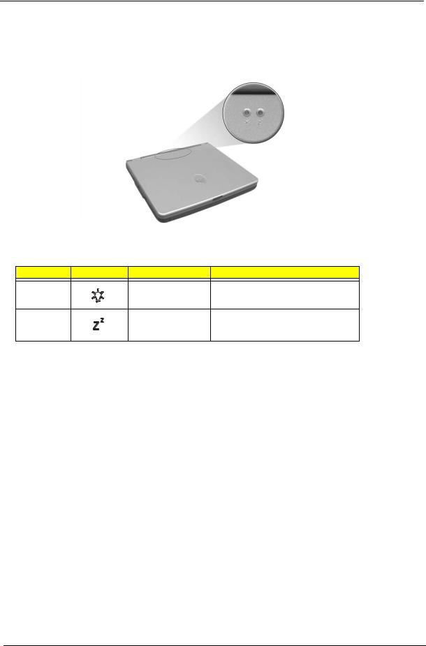
Understanding the icons
When the cover of your computer is closed, 2 easy-to-read icons are shown, indicating which state or feature is enabled or disabled.
# |
Icon |
Function |
Description |
1 |
|
Power |
Lights up when the computer is on. |
2 |
|
Sleep |
Lights when the computer enters Standby |
|
|
|
mode and blinks when it enters into or |
|
|
|
resumes from hibernation mode. |
Chapter 1 |
13 |

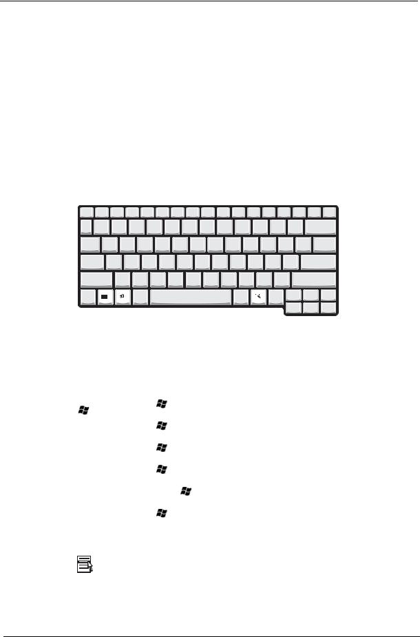
Keyboard
The keyboard has full-sized keys and an embedded keypad, separate cursor keys, two Windows keys and twelve function keys.
Special keys
Lock keys
The keyboard has three lock keys which you can toggle on and off.
|
|
|
|
|
|
|
|
|
|
|
|
Lock key |
Description |
||
|
|
|
|
Caps Lock |
When @is on, all alphabetic characters typed are in uppercase. |
||
@ |
|
|
|
|
|
|
|
Num Lock (Fn-F11) |
When ]is on, the embedded keypad is in numeric mode. The keys function |
||
] |
as a calculator (complete with the arithmetic operators ), -, *, and /). Use this mode |
||
|
when you need to do a lot of numeric data entry. A better solution would be to |
||
|
connect an external keypad. |
||
|
|
|
|
Scroll Lock (Fn-F12) |
When [is on, the screen moves one line up or down when you press the up |
||
[ |
or down arrow keys respectively. [does not work with some applications. |
||
|
|
|
|
Embedded numeric keypad
The embedded numeric keypad functions like a desktop numeric keypad. It is indicated by small characters located on the upper right corner of the keycaps. To simplify the keyboard legend, cursor-control key symbols are not printed on the keys.
|
|
|
|
|
|
|
|
14 |
|
TravelMate 240/ 250 |
|
Desired access |
Num lock on |
Num lock off |
|
|
|
Number keys on embedded |
Type numbers in a normal manner. |
|
keypad |
|
|
|
|
|
Cursor-control keys on embedded |
Hold Shift while using cursor-control keys. |
Hold Fn while using cursor-control |
keypad |
|
keys. |
|
|
|
Main keyboard keys |
Hold Fn while typing letters on embedded |
Type the letters in a normal manner. |
|
keypad. |
|
|
|
|
NOTE: If an external keyboard or keypad is connected to the computer, the Num Lock feature automatically shifts from the internal keyboard to the external keyboard or keypad.
Windows keys
The keyboard has two keys that perform Windows-specific functions.
|
|
|
|
|
|
|
|
|
|
Keys |
|
|
Description |
|
|
|
|
|
|
Windows logo key |
Start button. Combinations with this key perform shortcut functions. Below |
|||
|
are a few examples: |
|||
|
+ Tab (Activates next taskbar button) |
|||
|
+ E (Explores My Computer) |
|||
|
+ F (Finds Document) |
|||
|
+ M (Minimizes All) |
|||
|
j+ |
+ M (Undoes Minimize All) |
||
|
+ R (Displays the Run... dialog box) |
|||
|
|
|
|
|
Application key |
Opens a context menu (same as a right-click). |
|||
|
|
|
|
|
Chapter 1 |
15 |

Hot Keys
The computer employs hot keys or key combinations to access most of the computer’s controls like screen contrast and brightness, volume output and the BIOS Utility.
To activate hot keys, press and hold the Fn key before pressing the other key in the hot key combination.
Hot Key |
Icon |
Function |
Description |
Fn-l |
|
Hotkey help |
Displays a list of the hotkeys and their functions. |
Fn-m |
|
Setup |
Accesses the notebook configuration utility. |
Fn-n |
|
Power Management |
Switches between the power management scheme |
|
|
Scheme Toggle |
used by the computer (function available if supported |
|
|
|
by operating system). |
Fn-o |
|
Sleep |
Puts the computer in Sleep mode. |
Fn-p |
|
Display toggle |
Switches display output between the display screen, |
|
|
|
external monitor (if connected) and both the display |
|
|
|
screen and external monitor. |
Fn-q |
|
Screen blank |
Turns the display screen backlight off to save power. |
|
|
|
Press any key to return. |
Fn-r |
|
Touchpad Toggle |
Turns the internal touchpad on and off. |
Fn-s |
|
Speaker on/off |
Turns the speakers on and off; mutes the sound. |
Fn-w |
|
Volume up |
Increases the sound volume. |
Fn-y |
|
Volume down |
Decreases the sound volume. |
Fn-x |
|
Brightness up |
Increases the screen brightness. |
16 |
TravelMate 240/ 250 |
Hot Key |
Icon |
Function |
Description |
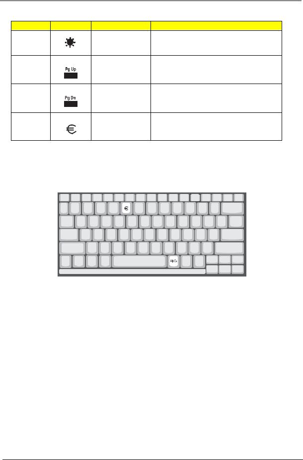
Fn-¨z |
|
Brightness down |
Decreases the screen brightness. |
Fn-{ |
|
Home |
Functions as the gkey. |
Fn-} |
|
End |
Functions as the dkey. |
aGr-Euro |
|
Euro |
Types the Euro symbol. |
The Euro symbol
If your keyboard layout is set to United States-International or United Kingdom or if you have a keyboard with a European layout, you can type the Euro symbol on your keyboard.
NOTE: for US keyboard users: The keyboard layout is set when you first set up Windows. For the Euro symbol to work, the keyboard layout has to be set to United States-international.
To verify the keyboard type:
1.Click on Start, Control Panel.
2.Double-click on Regional and Language Options.
3.Click on the language tab and click on Details.
4.Verify that the keyboard layout used for “EN English (United States) is set to United States-International. If not, select and click on ADD, then select United States-International and click on OK.
5.Click on OK.
To type the Euro symbol:
1.Locate the Euro symbol on your keyboard.
2.Open a text editor or word processor.
3.Hold aGr and press the Euro symbol.
Chapter 1 |
17 |
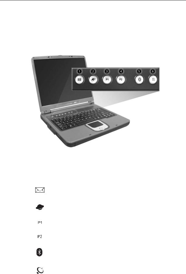
Launch Keys
Located at the top of the keyboard are five buttons. These buttons are called launch keys. They are designated as wireless LAN/Bluetooth, Web Browser button, mail button, P1 andP2. By default, P1 and P2 are users programmable. The Web Browser button, by default, is used to launch the internet browser The mail button is used to launch the e-mail application. The LED of the mail button will flash when the user has received an incoming email.
|
# |
Icon |
Function |
Description |
|
|
|
|
|
|
|
|
1 |
|
Email application |
|
|
|
|
|
|
|
|
|
2 |
|
Web browser |
Internet browser application |
|
|
|
|
|
|
|
|
3 |
|
P1 |
User-programmable |
|
|
|
|
|
|
|
|
4 |
|
P2 |
User-programmable |
|
|
|
|
|
|
|
|
5 |
|
Bluetooth |
Starts (optional) Bluetooth functionality and |
|
|
|
|
|
indicates that (optional) Bluetooth is enabled. |
|
|
|
|
|
|
|
|
6 |
|
Wireless |
Opens (optional) wireless connectivity and |
|
|
|
|
|
indicates status of (optional) wireless |
|
|
|
|
|
communication. |
|
|
|
|
|
|
|
|
|
|
|
|
|
18 |
TravelMate 240/ 250 |

Hardware Specifications and Configurations
System Board Major Chips
Item |
Controller |
|
|
System core logic |
Intel ICH4-M |
|
|
Super I/O controller |
NS PC87392 |
|
|
Audio controller |
Cirrus logic CS4299-XQ |
|
|
Video controller |
Intel 852GME (Montara-GT) |
|
|
Hard disk drive controller |
Embedded in Intel ICH4 |
|
|
Keyboard controller |
Mitsubish LPC keyboard controller M38857 |
|
|
CardBus Controller |
TI 1520 |
|
|
RTC |
Intel ICH4 |
|
|
Processor (for TravelMate 240)
Item |
Specification |
|
|
CPU type |
Intel Cerelon processor |
|
|
CPU package |
To 2.0GHz uFCBGA |
|
|
CPU core voltage |
High speed: 1.525V or 1.55V |
|
Low speed: 1.2V |
|
|
CPU I/O voltage |
High speed: 1.525V or 1.55V |
|
Low speed: 1.2V |
|
|
Processor (for TravelMate 250)
Item |
Specification |
|
|
CPU type |
Intel Petium 4 processor |
|
|
CPU package |
To 2.4GHz uFCBGA |
|
|
CPU core voltage |
1.525V |
|
|
CPU I/O voltage |
1.525V |
|
|
BIOS
Item |
Specification |
|
|
BIOS vendor |
Phoenix BIOS |
|
|
BIOS Version |
TM240 V1.00 for TM240; TM250 V1.00 for TM250 |
|
|
BIOS ROM type |
Flash ROM |
|
|
BIOS ROM size |
512KB |
|
|
BIOS package |
32 Pin PLCC |
|
|
Supported protocols |
ACPI 2.0 (if available, at least 1.0b), SMBIOS 2.3, PCI 2.2, Boot Block, |
|
PXE 2.0, Mobile PC2001, Hard Disk Password, INT 13h Extensions, PCI |
|
Bus Power Management interface Specification, EI Torito-Bootable CD- |
|
ROM Format Specification V1.0, Simple Boot Flag 1.0 |
|
|
BIOS password control |
Set by switch, see SW1 settings |
|
|
Second Level Cache
Item |
Specification |
|
|
Cache controller |
Built-in CPU |
|
|
Chapter 1 |
19 |

Second Level Cache
Item |
Specification |
Cache size |
128KB for TM240/512KB for TM250 |
|
|
1st level cache control |
Always Enabled |
|
|
2nd level cache control |
Always Enabled |
|
|
Cache scheme control |
Fixed-in write back |
|
|
System Memory
Item |
Specification |
|
|
Memory controller |
Intel 852GME (Montara-GT) |
|
|
Onboard memory size |
0MB |
|
|
DIMM socket number |
2 Sockets |
|
|
Supports memory size per socket |
128MB |
|
|
Supports maximum memory size |
2048MB |
|
|
Supports DIMM type |
DDR-DRAM |
|
|
Supports DIMM Speed |
266 MHz/333 MHz |
|
|
Supports DIMM voltage |
2.5 V |
|
|
Supports DIMM package |
200-pin so-DIMM |
|
|
Memory module combinations |
You can install memory modules in any combinations as long as they |
|
match the above specifications . |
|
|
Memory Combinations
Slot 1 |
Slot 2 |
Total Memory |
|
|
|
0MB |
128MB |
128 MB |
|
|
|
128MB |
0MB |
128 MB |
|
|
|
128MB |
128MB |
256 MB |
|
|
|
256MB |
0MB |
256MB |
|
|
|
0MB |
256MB |
256MB |
|
|
|
256MB |
128MB |
384MB |
|
|
|
128MB |
256MB |
384MB |
|
|
|
256MB |
256MB |
512MB |
|
|
|
0MB |
512MB |
512MB |
|
|
|
512MB |
128MB |
640MB |
|
|
|
256MB |
512MB |
768MB |
|
|
|
128MB |
512MB |
640MB |
|
|
|
512MB |
256MB |
768MB |
|
|
|
256MB |
128MB |
384MB |
|
|
|
512MB |
512MB |
1024MB |
|
|
|
0MB |
512MB |
512MB |
|
|
|
1024MB |
0MB |
1024MB |
|
|
|
1024MB |
128MB |
1152MB |
|
|
|
1024MB |
256MB |
1280MB |
|
|
|
1024MB |
512MB |
1536MB |
|
|
|
0MB |
1024MB |
1024MB |
|
|
|
128MB |
1024MB |
1152MB |
|
|
|
256MB |
1024MB |
1280MB |
|
|
|
20 |
TravelMate 240/ 250 |

Memory Combinations
Slot 1 |
Slot 2 |
Total Memory |
|
|
|
512MB |
1024MB |
1536MB |
|
|
|
Above table lists some system memory configurations. You may combine DIMMs with various capacities to form other combinations.
Modem Interface
Item |
Specification |
|
|
Chipset |
Internal Agere Scorpio chipset (Scorpio+CSP1037B) |
|
|
Fax modem data baud rate (bps) |
14.4K |
|
|
Data modem data baud rate (bps) |
56K |
|
|
Supports modem protocol |
V.90/V.92MDC |
|
|
Modem connector type |
RJ11 |
|
|
Modem connector location |
Rear side |
|
|
Floppy Disk Drive Interface
Item |
|
Specification |
|
|
|
|
|
Vendor & model name |
Mitsumi D353G 4515 |
|
|
|
MCI JU-226A033FC |
|
|
|
|
|
|
Floppy Disk Specifications |
|
|
|
|
|
|
|
Media recognition |
2DD (720KB) |
2HD (1.2 MB, 3 mode) |
2HD (1.44MB) |
|
|
|
|
Sectors/track |
9 |
15 |
18 |
|
|
|
|
Tracks |
80 |
80 |
80 |
|
|
|
|
Data transfer rate |
1 MB |
1.6 MB |
2 MB |
(Kbit/s) |
|
|
|
|
|
|
|
Rotational speed (RPM) |
300 |
360 |
300 |
|
|
|
|
Read/write heads |
2 |
|
|
|
|
|
|
Encoding method |
MFM |
|
|
|
|
|
|
Power Requirement |
|
|
|
|
|
|
|
Input Voltage (V) |
+5V |
|
|
|
|
|
|
Hard Disk Drive Interface
Item |
Specification |
|
|
|
|
|
|
|
|
Vendor & Model |
HITACHI |
HITACHI DK23EA-30 |
HITACHI DK23EA-40 |
HITACHI DK23EA-60 |
Name |
EUCALYPTUS |
HGST MORAGA |
HGST MORAGA |
HGST MORAGA |
|
DK23EA-20/ |
IC25N030ATMR04-0 |
IC25N040ATMR04-0 |
IC25N060ATMR04-0 |
|
HGST MORAGA |
TOSHIBA NEPTUNE |
|
TOSHIBA NEPTUNE |
|
IC25N020ATMR04-0 |
MK3021GAS |
|
MK6021GAS |
|
08K0632 |
|
|
|
|
IBM CASCADE |
|
|
|
|
IC25N020ATCS04-0 |
|
|
|
|
07N8325 |
|
|
|
|
|
|
|
|
Capacity (MB) |
20000 |
30000 |
40000 |
60000 |
|
|
|
|
|
Bytes per sector |
512 |
512 |
512 |
512 |
|
|
|
|
|
Logical heads |
16 |
16 |
16 |
16 |
|
|
|
|
|
Logical sectors |
63 |
63 |
63 |
63 |
|
|
|
|
|
Drive Format |
|
|
|
|
|
|
|
|
|
Logical cylinders |
42091/16383/16383 |
42091/16383/47080 |
42091/16383 |
42091/16383/47080 |
|
|
|
|
|
Chapter 1 |
21 |
 Loading...