


 Loading...
TravelMate 220/260
Service Guide
Service guide files and updates are available on the CSD web; for more information, please refer to http://csd.acer.com.tw
PART NO.: 49.49S01.021
PRINTED IN TAIWAN
Download Free Service Manual at http://printer1.blogspot.com

Revision History
Please refer to the table below for the updates made on Travelmate 220/260 service guide.
Date |
Chapter |
Updates |
|
|
|
01/03/2002 |
Chapter 1 |
Revised CPU Type from Celeron 933 to celeron 1.06 GHz |
|
|
with 256KB cache |
|
|
|
|
|
Revised Super I/O Controller to Mitsubishi 38859F |
|
|
|
|
|
Revised CPU package to PIII 1 GHz uFCBGA2 |
|
|
and to Celeron 1.06 GHz UFPGA2 |
|
|
|
|
|
Revised BIOS version to AOEO |
|
|
|
|
|
Delete IBM(IC25N030ATD) Specifications for HDD |
|
|
Interface |
|
|
|
|
|
Changed TEAC to Mitsubishi and its specifications in CD- |
|
|
ROM interface. |
|
|
|
|
Chapter 5 |
Revised PCB N0. to 01213-1 |
|
|
|
|
Appendix A |
Revison: ‘Note” was deleted. |
|
|
|
|
Appendix B |
Remove ELPIDA 128 and 256MB for memory specifications |
|
|
|
|
|
Remove TEAC for DVD-ROM specifications. |
|
|
|
|
|
Add (DVD + CD-RW) for Combo driver. |
|
|
|
|
|
Remove Simplo Ni-MH, Sanyo Li-ION, Sanyo Ni-MH |
|
|
specifications for battery. |
|
|
|
|
|
Remove US 2 pin for Power Code: |
|
|
|
01/18/2002 |
Chapter 1 |
Change DVD-RW to DVD/CD-R/CD-RW and modify battery |
|
|
specs. |
|
|
|
|
|
. |
|
|
|
II
Download Free Service Manual at http://printer1.blogspot.com

Copyright
Copyright © 2001 by Acer Incorporated. All rights reserved. No part of this publication may be reproduced, transmitted, transcribed, stored in a retrieval system, or translated into any language or computer language, in any form or by any means, electronic, mechanical, magnetic, optical, chemical, manual or otherwise, without the prior written permission of Acer Incorporated.
Disclaimer
The information in this guide is subject to change without notice.
Acer Incorporated makes no representations or warranties, either expressed or implied, with respect to the contents hereof and specifically disclaims any warranties of merchantability or fitness for any particular purpose. Any Acer Incorporated software described in this manual is sold or licensed "as is". Should the programs prove defective following their purchase, the buyer (and not Acer Incorporated, its distributor, or its dealer) assumes the entire cost of all necessary servicing, repair, and any incidental or consequential damages resulting from any defect in the software.
Acer is a registered trademark of Acer Corporation. Intel is a registered trademark of Intel Corporation.
Pentium and Pentium II/III are trademarks of Intel Corporation.
Other brand and product names are trademarks and/or registered trademarks of their respective holders.
Download Free Service Manual at http://printer1.blogspot.com
III

Conventions
The following conventions are used in this manual:
Screen messages |
Denotes actual messages that appear |
|
on screen. |
|
|
NOTE |
Gives bits and pieces of additional |
|
information related to the current |
|
topic. |
|
|
WARNING |
Alerts you to any damage that might |
|
result from doing or not doing specific |
|
actions. |
|
|
CAUTION |
Gives precautionary measures to |
|
avoid possible hardware or software |
|
problems. |
|
|
IMPORTANT |
Reminds you to do specific actions |
|
relevant to the accomplishment of |
|
procedures. |
|
|
IV
Download Free Service Manual at http://printer1.blogspot.com

Preface
Before using this information and the product it supports, please read the following general information.
1.This Service Guide provides you with all technical information relating to the BASIC CONFIGURATION decided for Acer's "global" product offering. To better fit local market requirements and enhance product competitiveness, your regional office MAY have decided to extend the functionality of a machine (e.g. add-on card, modem, or extra memory capability). These LOCALIZED FEATURES will NOT be covered in this generic service guide. In such cases, please contact your regional offices or the responsible personnel/channel to provide you with further technical details.
2.Please note WHEN ORDERING FRU PARTS, that you should check the most up-to-date information available on your regional web or channel. If, for whatever reason, a part number change is made, it will not be noted in the printed Service Guide. For ACER-AUTHORIZED SERVICE PROVIDERS, your Acer office may have a DIFFERENT part number code to those given in the FRU list of this printed Service Guide. You MUST use the list provided by your regional Acer office to order FRU parts for repair and service of customer machines.
Download Free Service Manual at http://printer1.blogspot.com
V

VI
Download Free Service Manual at http://printer1.blogspot.com

Table of Contents
Chapter 1 |
System Introduction |
1 |
Features . . . . . . . . . . . . . . . . . . . . . . . . . . . . . . . . . . . . . . . . . . . . . . . . . . . . . . . .1
System Block Diagram . . . . . . . . . . . . . . . . . . . . . . . . . . . . . . . . . . . . . . . . . . . . .3
Board Layout . . . . . . . . . . . . . . . . . . . . . . . . . . . . . . . . . . . . . . . . . . . . . . . . . . . .4
Top View . . . . . . . . . . . . . . . . . . . . . . . . . . . . . . . . . . . . . . . . . . . . . . . . . . . .4
Bottom View . . . . . . . . . . . . . . . . . . . . . . . . . . . . . . . . . . . . . . . . . . . . . . . . .5
Panel . . . . . . . . . . . . . . . . . . . . . . . . . . . . . . . . . . . . . . . . . . . . . . . . . . . . . . . . . . .6
Front Panel . . . . . . . . . . . . . . . . . . . . . . . . . . . . . . . . . . . . . . . . . . . . . . . . . .6
Left Panel . . . . . . . . . . . . . . . . . . . . . . . . . . . . . . . . . . . . . . . . . . . . . . . . . . .7
Right Panel . . . . . . . . . . . . . . . . . . . . . . . . . . . . . . . . . . . . . . . . . . . . . . . . . .8
Rear Panel . . . . . . . . . . . . . . . . . . . . . . . . . . . . . . . . . . . . . . . . . . . . . . . . . .8
Bottom Panel . . . . . . . . . . . . . . . . . . . . . . . . . . . . . . . . . . . . . . . . . . . . . . . .9
Indicators . . . . . . . . . . . . . . . . . . . . . . . . . . . . . . . . . . . . . . . . . . . . . . . . . . . . . .10
Keyboard . . . . . . . . . . . . . . . . . . . . . . . . . . . . . . . . . . . . . . . . . . . . . . . . . . . . . .11
Special keys . . . . . . . . . . . . . . . . . . . . . . . . . . . . . . . . . . . . . . . . . . . . . . . .11
Hot Keys . . . . . . . . . . . . . . . . . . . . . . . . . . . . . . . . . . . . . . . . . . . . . . . . . . . . . . .13
Touchpad . . . . . . . . . . . . . . . . . . . . . . . . . . . . . . . . . . . . . . . . . . . . . . . . . . . . . .15
Touchpad basics . . . . . . . . . . . . . . . . . . . . . . . . . . . . . . . . . . . . . . . . . . . . .15
Hardware Specifications and Configurations . . . . . . . . . . . . . . . . . . . . . . . . . . .17
Chapter 2 |
System Utilities |
30 |
BIOS Setup Utility . . . . . . . . . . . . . . . . . . . . . . . . . . . . . . . . . . . . . . . . . . . . . . . .30
Multi-Boot Menu . . . . . . . . . . . . . . . . . . . . . . . . . . . . . . . . . . . . . . . . . . . . . . . . .31
Navigating the BIOS Utility . . . . . . . . . . . . . . . . . . . . . . . . . . . . . . . . . . . . .31
System Information . . . . . . . . . . . . . . . . . . . . . . . . . . . . . . . . . . . . . . . . . . .32
Basic System Settings . . . . . . . . . . . . . . . . . . . . . . . . . . . . . . . . . . . . . . . .33
Startup Configuration . . . . . . . . . . . . . . . . . . . . . . . . . . . . . . . . . . . . . . . . .33
Onboard Device Configuration . . . . . . . . . . . . . . . . . . . . . . . . . . . . . . . . . .35
System Security . . . . . . . . . . . . . . . . . . . . . . . . . . . . . . . . . . . . . . . . . . . . .36
Load Default Settings . . . . . . . . . . . . . . . . . . . . . . . . . . . . . . . . . . . . . . . . .39
BIOS Flash Utility . . . . . . . . . . . . . . . . . . . . . . . . . . . . . . . . . . . . . . . . . . . . . . . .40
System Utility Diskette . . . . . . . . . . . . . . . . . . . . . . . . . . . . . . . . . . . . . . . . . . . .40
System Diagnostic Diskette . . . . . . . . . . . . . . . . . . . . . . . . . . . . . . . . . . . . . . . .40
Running PQA Diagnostics Program . . . . . . . . . . . . . . . . . . . . . . . . . . . . . .41
Chapter 3 |
Machine Disassembly and Replacement |
44 |
General Information . . . . . . . . . . . . . . . . . . . . . . . . . . . . . . . . . . . . . . . . . . . . . .45
Before You Begin . . . . . . . . . . . . . . . . . . . . . . . . . . . . . . . . . . . . . . . . . . . .45
Disassembly Procedure Flowchart . . . . . . . . . . . . . . . . . . . . . . . . . . . . . . . . . . .46
Removing the Battery Pack . . . . . . . . . . . . . . . . . . . . . . . . . . . . . . . . . . . . . . . .49
Removing the Battery Cover . . . . . . . . . . . . . . . . . . . . . . . . . . . . . . . . . . . .49
Removing the CD-ROM Drive Module . . . . . . . . . . . . . . . . . . . . . . . . . . . . . . . .50
Disassembling the CD-ROM Drive Module . . . . . . . . . . . . . . . . . . . . . . . . .50
Removing the Hard Disk Drive Module . . . . . . . . . . . . . . . . . . . . . . . . . . . . . . . .52
Disassembling the Hard Disk Drive Module . . . . . . . . . . . . . . . . . . . . . . . .52
Removing the Extended Memory . . . . . . . . . . . . . . . . . . . . . . . . . . . . . . . . . . . .54
Removing the Modem Board . . . . . . . . . . . . . . . . . . . . . . . . . . . . . . . . . . . . . . .55
Disassembling the LCD . . . . . . . . . . . . . . . . . . . . . . . . . . . . . . . . . . . . . . . . . . .56
Removing the Hinge Caps . . . . . . . . . . . . . . . . . . . . . . . . . . . . . . . . . . . . .56
Removing the Middle Cover . . . . . . . . . . . . . . . . . . . . . . . . . . . . . . . . . . . .56
Removing the Launch Board . . . . . . . . . . . . . . . . . . . . . . . . . . . . . . . . . . .56
Removing the Cable Cover . . . . . . . . . . . . . . . . . . . . . . . . . . . . . . . . . . . . .57
Removing the Keyboard . . . . . . . . . . . . . . . . . . . . . . . . . . . . . . . . . . . . . . .57
Removing the LCD Module . . . . . . . . . . . . . . . . . . . . . . . . . . . . . . . . . . . . .58
Download Free Service Manual at http://printer1.blogspot.com
VII

Table of Contents |
|
|
|
Removing the Video Capture Kit Covers . . . . . . . . . . . . . . . . . . . . . . . . . |
.59 |
|
Removing the 14.1” TFT LCD Bezel . . . . . . . . . . . . . . . . . . . . . . . . . . . . . . |
59 |
|
Removing the 13.3” TFT LCD Bezel . . . . . . . . . . . . . . . . . . . . . . . . . . . . . . |
60 |
|
Removing the Speakers (14.1” TFT LCD) . . . . . . . . . . . . . . . . . . . . . . . . . |
61 |
|
Removing the Speakers (13.3” TFT LCD) . . . . . . . . . . . . . . . . . . . . . . . . . |
61 |
|
Removing the Inverter Board . . . . . . . . . . . . . . . . . . . . . . . . . . . . . . . . . . . |
62 |
|
Removing the 14.1” TFT LCD . . . . . . . . . . . . . . . . . . . . . . . . . . . . . . . . . . . |
63 |
|
Removing the 13.3” TFT LCD . . . . . . . . . . . . . . . . . . . . . . . . . . . . . . . . . . . |
64 |
|
Removing the 13.3” TFT LCD Brackets . . . . . . . . . . . . . . . . . . . . . . . . . . . |
64 |
|
Removing the LCD Coaxial Cable . . . . . . . . . . . . . . . . . . . . . . . . . . . . . . . |
65 |
|
Removing the Microphone Cable . . . . . . . . . . . . . . . . . . . . . . . . . . . . . . . . |
66 |
Disassembling the Main Unit . . . . . . . . . . . . . . . . . . . . . . . . . . . . . . . . . . . . . . . |
67 |
|
|
Removing the CPU Heat Sink Plate . . . . . . . . . . . . . . . . . . . . . . . . . . . . . . |
67 |
|
Removing the RTC Battery . . . . . . . . . . . . . . . . . . . . . . . . . . . . . . . . . . . . . |
67 |
|
Removing the Touch Pad Frame . . . . . . . . . . . . . . . . . . . . . . . . . . . . . . . . |
67 |
|
Removing the Touch Pad Cable . . . . . . . . . . . . . . . . . . . . . . . . . . . . . . . . . |
68 |
|
Removing the Upper Case . . . . . . . . . . . . . . . . . . . . . . . . . . . . . . . . . . . . . |
69 |
|
Removing the RTC Battery Holder . . . . . . . . . . . . . . . . . . . . . . . . . . . . . . . |
70 |
|
Removing the Floppy Disk Drive Module . . . . . . . . . . . . . . . . . . . . . . . . . . |
70 |
|
Disassembling the Floppy Disk Drive Module . . . . . . . . . . . . . . . . . . . . . . . |
71 |
|
Removing the Charger Plate . . . . . . . . . . . . . . . . . . . . . . . . . . . . . . . . . . . . |
72 |
|
Removing the CPU Heat Sink . . . . . . . . . . . . . . . . . . . . . . . . . . . . . . . . . . . |
72 |
|
Removing the CPU Fan . . . . . . . . . . . . . . . . . . . . . . . . . . . . . . . . . . . . . . . |
73 |
|
Removing the Audio Board . . . . . . . . . . . . . . . . . . . . . . . . . . . . . . . . . . . . . |
73 |
|
Removing the Main Board . . . . . . . . . . . . . . . . . . . . . . . . . . . . . . . . . . . . . |
74 |
|
Removing the PCMCIA Slot . . . . . . . . . . . . . . . . . . . . . . . . . . . . . . . . . . . . |
75 |
|
Removing the I/O Port Bracket . . . . . . . . . . . . . . . . . . . . . . . . . . . . . . . . . . |
76 |
|
Removing the Modem Cable . . . . . . . . . . . . . . . . . . . . . . . . . . . . . . . . . . . |
77 |
Chapter 4 |
Troubleshooting |
78 |
System Check Procedures . . . . . . . . . . . . . . . . . . . . . . . . . . . . . . . . . . . . . . . . . |
79 |
|
|
External Diskette Drive Check . . . . . . . . . . . . . . . . . . . . . . . . . . . . . . . . . . |
79 |
|
External CD-ROM Drive Check . . . . . . . . . . . . . . . . . . . . . . . . . . . . . . . . . |
79 |
|
Keyboard or Auxiliary Input Device Check . . . . . . . . . . . . . . . . . . . . . . . . . |
80 |
|
Memory Check . . . . . . . . . . . . . . . . . . . . . . . . . . . . . . . . . . . . . . . . . . . . . . |
80 |
|
Power System Check . . . . . . . . . . . . . . . . . . . . . . . . . . . . . . . . . . . . . . . . . |
80 |
|
Touchpad Check . . . . . . . . . . . . . . . . . . . . . . . . . . . . . . . . . . . . . . . . . . . . . |
82 |
Power-On Self-Test (POST) Error Message . . . . . . . . . . . . . . . . . . . . . . . . . . . |
83 |
|
Index of Error Messages . . . . . . . . . . . . . . . . . . . . . . . . . . . . . . . . . . . . . . . . . . . |
84 |
|
Index of Symptom-to-FRU Error Message . . . . . . . . . . . . . . . . . . . . . . . . . . . . . |
87 |
|
Intermittent Problems . . . . . . . . . . . . . . . . . . . . . . . . . . . . . . . . . . . . . . . . . . . . . |
90 |
|
Undetermined Problems . . . . . . . . . . . . . . . . . . . . . . . . . . . . . . . . . . . . . . . . . . . |
91 |
|
Index of AFlash BIOS Error Message . . . . . . . . . . . . . . . . . . . . . . . . . . . . . . . . . |
92 |
|
Index of PQA Diagnostic Error Code, Message . . . . . . . . . . . . . . . . . . . . . . . . . |
93 |
|
Chapter 5 |
Jumper and Connector Locations |
94 |
Top View . . . . . . . . . . . . . . . . . . . . . . . . . . . . . . . . . . . . . . . . . . . . . . . . . . . . . . . |
94 |
|
Bottom View . . . . . . . . . . . . . . . . . . . . . . . . . . . . . . . . . . . . . . . . . . . . . . . . . . . . |
96 |
|
Chapter 6 |
FRU (Field Replaceable Unit) List |
98 |
Exploded Diagram . . . . . . . . . . . . . . . . . . . . . . . . . . . . . . . . . . . . . . . . . . . . . . .99
Download Free Service Manual at http://printer1.blogspot.com
VIII

Table of Contents
Appendix A Model Definition and Configuration |
110 |
Appendix B Test Compatible Components |
112 |
Microsoft Windows XP Home Edition Environment Test |
. . . . . . . . . . . . . . . . .113 |
Appendix C Online Support Information |
114 |
Index |
116 |
Download Free Service Manual at http://printer1.blogspot.com
IX

Chapter 1
System Introduction
Features
This computer was designed with the user in mind. Here are just a few of its many features:
Performance
!Intel® Mobile Pentium® III with 512KB cache or Celeron® CPU 1.06 GHz processor with 256KB cache
!64-bit memory bus
!AcerMedia bay (removable CD-ROM, DVD-ROM, CD-RW or DVD/CD-R/RW drive)
!Built-in floppy drive
!High-capacity, Enhanced-IDE hard disk
!Power management system with ACPI (Advanced Configuration Power Interface)
Multimedia
!16-bit high-fidelity AC’97 stereo audio with 3D sound and wavetable synthesizer
!Built-in dual speakers with microphone
!Highspeed CD-ROM, DVD-ROM, CD-RW, or DVD/CD-R/RW, and drive (AcerMedia Bay)
!USB video capture kit option
Connectivity
!PS/2 interface, which also can be configured as keyboard/keypad interface.
!85/88 key keyboard, which is IBM PC/AT keyboard compatible.
!Two Universal Serial Bus (USB) Ports
!CD-ROM/DVD-ROM/DVD/CD-R/RW Swappable Module
!RJ-11 for 56Kbps fax/modem
!Upgradeable memory and hard disk
!ECP/EPP Compliant parallel port.
!RS-232 (16550 compatible) serial port
Download Free Service Manual at http://printer1.blogspot.com
Chapter 1 |
1 |
Human-centric Design and Ergonomics
!All-in-one design (CD-ROM, floppy disk drive, hard disk drive)
!Sleek, smooth and stylish design
!Full-sized keyboard
!Ergonomically centred touchpad pointing device
Expansion
!One Type III or one Type II CardBus PC card (formerly PCMCIA) slot with ZV (zoomed video) support
!Upgrageable memory and hard disk
Display
!13.3” or 14.1” TFT LCD displaying 32-bit true-color at 1024x768 XGA resolution
!3D capabilities
!Supports other output display devices such as LCD projection panels for large audience presentations
!“Automatic LCD dim” feature that automatically decides the best settings for your display and conserves power.
!Simultaneous LCD and CRT display support
!Dual display capacity
Video performance
2X AGP video graphic accelerator with 8MB shared from system memory to boost video performance.
Simultaneous display
The computer’s large display and multimedia capabilities are great for giving presentations. If you prefer, you can also connect an external monitor when giving presentations. This computer has built-in AGP and VGA display system to support simultaneous LCD and CRT display. Simultaneous display allows you to control the presentation from your computer and at the same time face your audience. You can also connect other output display devices such as LCD projection panels for large-audience presentations.
Dual Display
The computer’s unique graphics chip takes advantage of Windows ME’s multi-display capability, allowing you to extend your desktop to an external display device, such as an external monitor projector. With this feature enabled, you can move program windows to/from the computer LCD and the external monitor.
Power management
The power management system incorporates an "automatic LCD dim" feature that automatically dims the LCD when the computer is powered by a battery pack to conserve battery power. See “Power Management” on page 26 for more information on power management features.
Opening and closing the display
To open the display, slide the display cover latch to the left and lift up the cover. Then tilt it to a comfortable viewing position. The computer employs a microswitch that turns off the display (and enters standby mode) to conserve power when you close the display cover, and turns it back on when you open the display cover.
NOTE: If an external monitor is connected, the computer turns off the display (but does not enter standby mode) when you close the display cover.
To close the display cover, fold it down gently until the display cover latch clicks into place.
WARNING: To avoid damaging the display, do not slam it when you close it. Also, do not place any object on top of the computer when the display is closed.
Download Free Service Manual at http://printer1.blogspot.com
2 |
Chapter 1 |
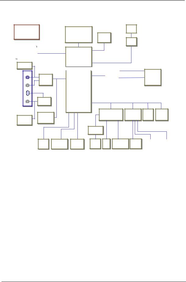
System Block Diagram
CLK GEN
|
|
|
MEMBUS |
|
SO-DIMM*2 |
|
|
|
|
133MHz |
|
|
|
|
|
INT. MIC |
|
|
||
I |
T. |
IC |
|
|
|
|
MIC IN |
|
|
|
|
|
AC’97 |
AC-LINK |
|
|
|
’ |
|
|
LINE IN |
CODEC |
|
|
|
EC |
|
||
|
|
|
CS4299 |
|
|
|
|
S4299 |
|
|
|
VR |
|
|
|
LINE OUT |
OP AMP |
|
|
|
|
|
|
|
|
|
|
TPA0202 |
|
|
|
|
TPA0202 |
|
|
AUDIO |
|
|
|
|
BOARD |
MODEM |
|
|
|
INT |
|
||
|
EM |
|
||
|
I |
T |
CDC Card |
|
SPEAKER |
rd |
|
||
SPE |
ER |
|
|
|
Mobile CPU |
|
LCD |
||
|
ile |
|
|
|
Taulatin 1G |
CRTT |
LVDZ |
||
T |
l |
tin |
|
|
Celeron 933, 866 |
CONN |
|
||
l |
r |
, |
VCH |
|
|
|
|
|
|
HOST BUS |
133MHz |
|
|
|
RGB
Almadorl rM
GMCH--MG
830MG |
DVO BUS/66MHz |
|
|||||
830 |
|
|
|
||||
|
|
|
|
|
|
|
|
HUB I/F |
66MHz |
|
|
|
|
||
|
|
PCI BUS |
|
CARDBUS |
|
|
|
|
|
|
|
|
0Z6912 |
|
PWR SW |
|
|
|
|
|
0Z6912 |
|
|
|
|
|
|
|
|
|
MIC2562A |
|
|
|
|
|
|
|
I 2562A |
|
|
|
|
|
|
|
|
|
|
|
|
|
|
|
|
|
|
|
|
|
LAN |
|
|
ICH3-M |
|
|
L |
|
|
||
|
|
RTL8100-L |
|
|
|||
|
|
|
|
|
RTL8100-L |
|
|
|
|
|
|
|
|
|
|
|
|
|
|
|
LPC BUS |
||
SMsCsCSIOSIO KBC
LPC47N227L --MN M3885938859
PIDE SIDE
MAX3243 |
USB*2 |
PRIMARY |
CD-ROM |
RS232 |
FDD |
PRN-PORT |
PS/2 |
|||
P I |
Y |
/2 |
|||||||
S *2 |
HDD |
|
- |
S |
F |
P |
-P |
T |
CONN |
CARDBUSS
ONE SLOTL T
|
LPC |
FWH |
L |
DEBUG |
|
F |
EB |
|
CONN |
|
TOUCH |
|
INT KB |
|
T |
|
|
|
PAD |
|
I T |
|
P |
|
|
|
|
|
|
Download Free Service Manual at http://printer1.blogspot.com
Chapter 1 |
3 |
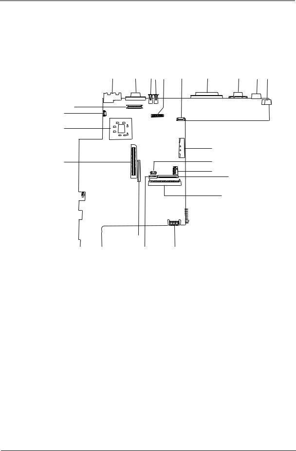
Board Layout
Top View
4 |
5 |
6 7 8 |
9 |
10 |
11 |
12 13 |
3 |
|
|
|
|
|
|
2 |
|
|
|
|
|
|
1 |
|
|
|
|
|
|
|
|
|
|
|
14 |
|
22 |
|
|
|
|
15 |
|
|
|
|
|
|
16 17 |
|
|
|
|
|
|
18 |
|
21
1 |
CPU (on board) |
12 |
PS/2 Port |
2 |
Fan Connector |
13 |
DC-in Port |
3 |
Inverter connector |
14 |
CD-ROM Connector |
4 |
RJ45+RJ11 |
15 |
RTC battery connecto |
5 |
External Display Port |
16 |
Switch |
6 |
USB Port 0 |
17 |
Internal Keyboard Cable Connector |
7 |
USB Port 1 |
18 |
HDD Connector |
8 |
LCD Connecto |
19 |
Golden Finger |
9 |
Hot Key Connector |
20 |
TouchPad Cable Connector |
10 |
Parallel Port |
21 |
FDD Connector |
11 |
Serial Port |
22 |
Cardbus Connector |
Download Free Service Manual at http://printer1.blogspot.com
4 |
Chapter 1 |
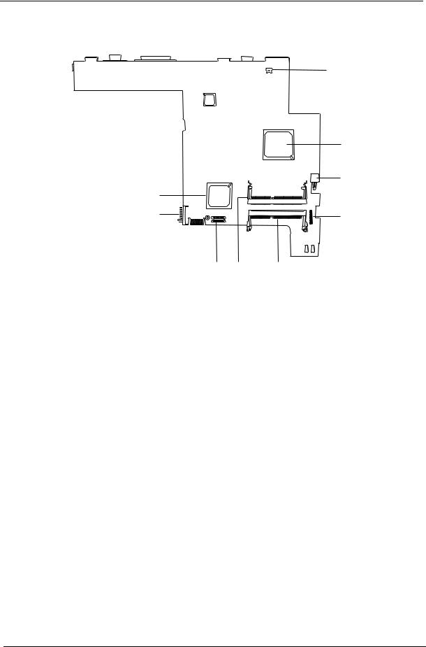
Bottom View
9
8
1Modem Connector
2North Bridge(82830MG)
3Power Switch
4Audio Board Connector
5DIMM 2 Socket
1
2
3
4
7 6 5
6DIMM 1 Socket
7Modem Card Cable Connector
8Battery Connecto
9South Bridge (ICH3-M)
Download Free Service Manual at http://printer1.blogspot.com
Chapter 1 |
5 |
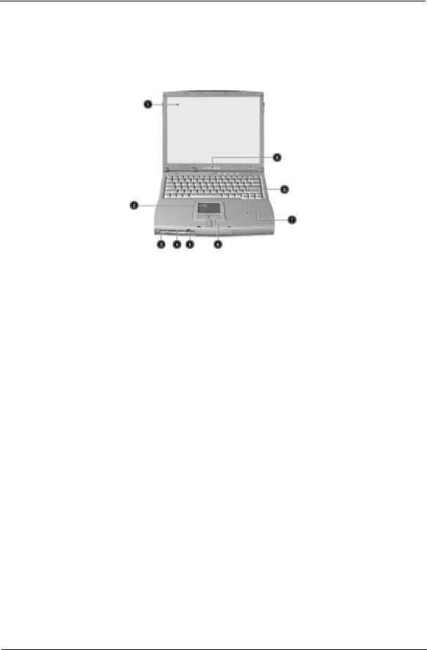
Panel
Ports allow you to connect peripheral devices to your computer as you would with a desktop PC.
Front Panel
# |
Item |
Description |
|
|
|
1 |
Display screen |
Also called LCD (Liquid Crystal Display), displays computer |
|
|
output. |
|
|
|
2 |
Touchpad |
Touch-sensitive pointing device which functions like a |
|
|
computer mouse. |
|
|
|
3 |
Floppy activity indicator |
LED (light-emitting diodes) that turn on and off when the |
|
|
floppy is active. |
|
|
|
4 |
Floppy drive |
Internal diskette drive, accepts 3.5-inch floppy diskettes |
|
|
|
5 |
Floppy disk eject button |
Push this button to eject the floppy disk |
|
|
|
6 |
Click button (left, center and right) |
The left and right buttons function like the left and right |
|
|
mouse buttons, the center button serves as a scroll up/ |
|
|
down button. |
|
|
|
7 |
Palmrest |
Comfortable support area for your hands when you use the |
|
|
computer. |
|
|
|
8 |
Keyboard |
Inputs data into your computer. |
|
|
|
9 |
Status indicators |
LEDs (Light Emitting Diodes) that turn on and off to show |
|
|
the status of the computer and its functions and |
|
|
components. |
|
|
|
Download Free Service Manual at http://printer1.blogspot.com
6 |
Chapter 1 |
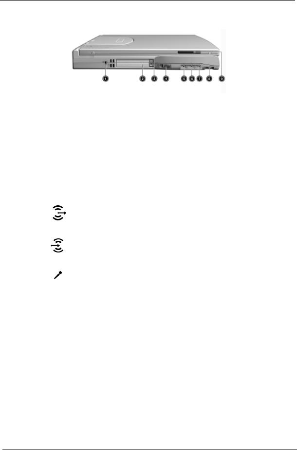
Left Panel
# |
Icon |
Item/ Port |
Connects to... |
|||||
|
|
|
|
|
|
|
|
|
1 |
|
|
|
|
|
|
Security keylock |
Kensington-compatible key-based computer |
|
|
|
|
|
|
|
|
security lock. |
|
|
|
|
|
|
|
|
|
2 |
|
|
|
|
|
|
PCMCIA (PC card) Port |
Connects to one Type II or one Type III 16-bit PC |
|
|
|
|
|
|
|
|
card or 32-bit CardBus PC Card. |
|
|
|
|
|
|
|
|
|
|
|
|
|
|
|
|
|
|
|
|
|
|
|
|
|
|
|
3 |
|
|
|
|
|
|
Eject button |
Eject PC cards from the card slots. |
|
|
|
|
|
|
|
|
|
4 |
|
|
|
|
|
|
Power switch |
Turns on the computer power. |
|
|
|
|
|
|
|
|
|
5 |
|
|
|
|
|
|
Speaker/ headphone-out jack |
Connects to audio line-out devices (e.g., |
|
|
|
|
|
|
|
|
speakers, headphones) |
|
|
|
|
|
|
|
|
|
6 |
|
|
|
|
|
|
Line-in jack |
Accepts audio line-in devices (e.g., audio CD |
|
|
|
|
|
|
|
|
player, stereo walkman). |
|
|
|
|
|
|
|
|
|
7 |
|
|
|
|
|
|
Microphone-in jack |
Accepts a mono/stereo condenser microphone. |
|
|
|
|
|
|
|
|
|
8 |
|
|
|
|
|
|
Volume control |
Controls the volume of the speakers. |
|
|
|
|
|
|
|
|
|
9 |
|
|
|
|
|
|
Video capture kit slot |
Accepts the video capture kit option on the left |
|
|
|
|
|
|
|
|
side of the computer. |
|
|
|
|
|
|
|
|
|
Download Free Service Manual at http://printer1.blogspot.com
Chapter 1 |
7 |
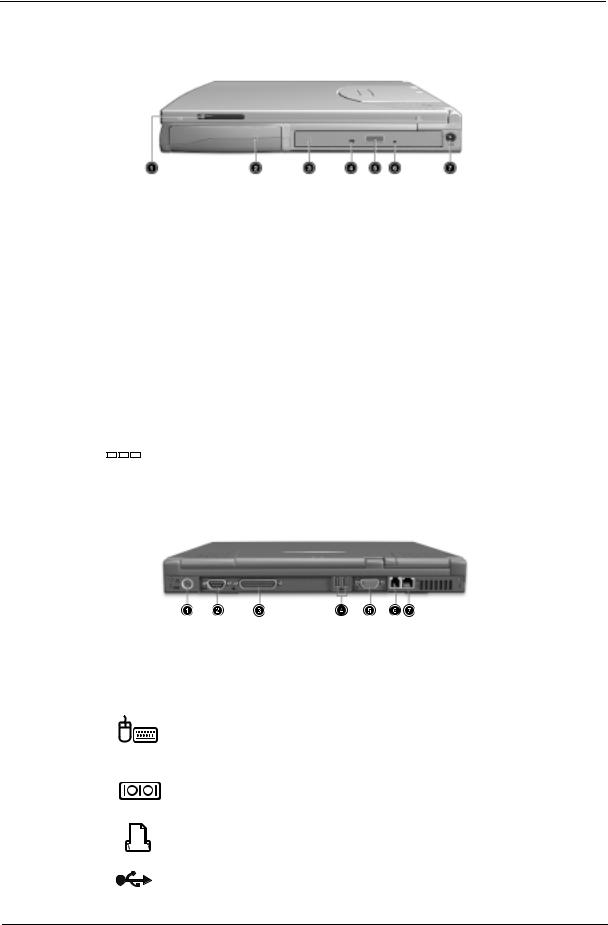
Right Panel
# |
|
Icon |
Item/ Port |
Connects to... |
|||||
|
|
|
|
|
|
|
|
|
|
1 |
|
|
|
|
|
|
|
Video capture kit slot |
Accepts the video capture kit option on the |
|
|
|
|
|
|
|
|
|
right side of the computer. |
|
|
|
|
|
|
|
|
|
|
2 |
|
|
|
|
|
|
|
Battery bay |
Houses the computer’s battery pack. |
|
|
|
|
|
|
|
|
|
|
3 |
|
|
|
|
|
|
|
AcerMedia drive |
Houses removable media drive modules. |
|
|
|
|
|
|
|
|
|
|
4 |
|
|
|
|
|
|
|
LED indicator |
Lights up when the AcerMedia drive is active. |
|
|
|
|
|
|
|
|
|
|
5 |
|
|
|
|
|
|
|
Eject button |
Ejects the compact disc from the drive. |
|
|
|
|
|
|
|
|
|
|
6 |
|
|
|
|
|
|
|
Emergency eject slot |
Ejects the compact discs when the computer |
|
|
|
|
|
|
|
|
|
is turned off. |
|
|
|
|
|
|
|
|
|
|
7 |
|
|
|
|
|
|
|
Power Jack |
Connects to an AC adapter |
|
|
|
|
|
|
|
|
|
|
|
|
|
|
|
|
|
|
|
|
|
|
|
|
|
|
|
|
|
|
|
|
|
|
|
|
|
|
|
|
|
|
|
|
|
|
|
|
|
|
Rear Panel
l
# |
Icon |
Port |
Connects to... |
|||||
|
|
|
|
|
|
|
|
|
1 |
|
|
|
|
|
|
PS/2 port |
Connects to any PS/2-compatible devices |
|
|
|
|
|
|
|
|
(e.g., PS/2 keyboard/mouse/keypad) |
|
|
|
|
|
|
|
|
|
2 |
|
|
|
|
|
|
Serial port |
Connects to a serial device (e.g., serial |
|
|
|
|
|
|
|
|
mouse) |
|
|
|
|
|
|
|
|
|
3 |
|
|
|
|
|
|
Parallel port |
Connects to a parallel device (e.g., parallel |
|
|
|
|
|
|
|
|
printer) |
|
|
|
|
|
|
|
|
|
|
|
|
|
|
|
|
|
|
|
|
|
|
|
|
|
|
|
|
|
|
|
|
|
|
|
|
|
|
|
|
|
|
|
|
|
|
|
|
|
|
|
|
|
|
4 |
|
|
|
|
|
|
USB port (two) |
Connects to any Universal Serial Bus |
|
|
|
|
|
|
|
|
devices(e.g., USB mouse, USB camera). |
|
|
|
|
|
|
|
|
|
Download Free Service Manual at http://printer1.blogspot.com
8 |
Chapter 1 |
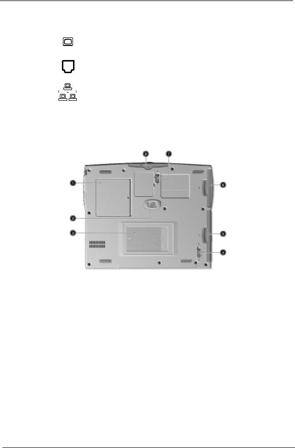
# |
|
|
Icon |
Port |
Connects to... |
||||
|
|
|
|
|
|
|
|
|
|
5 |
|
|
|
|
|
|
|
External display port |
Connects to a display device (e.g., external |
|
|
|
|
|
|
|
|
|
monitor, LCD projector) and displays up to |
|
|
|
|
|
|
|
|
|
64K colors at 1280x1024 resolution |
|
|
|
|
|
|
|
|
|
|
6 |
|
|
|
|
|
|
|
Modem jack |
Connects to the phone line |
|
|
|
|
|
|
|
|
|
|
7 |
|
|
|
|
|
|
|
Network jack |
Connects to an Ethernet 10/100-based |
|
|
|
|
|
|
|
|
|
network |
|
|
|
|
|
|
|
|
|
|
|
|
|
|
|
|
|
|
|
|
Bottom Panel
# |
Item |
Description |
|
|
|
1 |
Memory compartment |
Houses the computer’s main memory. |
|
|
|
2 |
Hard disk anti-shock protection |
Protects your hard disk against shocks. |
|
|
|
3 |
Personal identification slot |
Insert a business card or similar-sized identification card to |
|
|
personalize your computer. |
|
|
|
4 |
AcerMedia bay release latch |
Unlatches the AcerMedia drive for removal or swapping. |
|
|
|
5 |
AcerMedia bay |
Houses an AcerMedia drive module. |
|
|
|
6 |
Battery bay |
Houses the computer’s battery pack. |
|
|
|
7 |
Battery release latch |
Unlatches the battery to remove the battery pack. |
|
|
|
8 |
Hard disk bay |
Houses the computer’s hard disk (secured by a screw). |
|
|
|
Download Free Service Manual at http://printer1.blogspot.com
Chapter 1 |
9 |
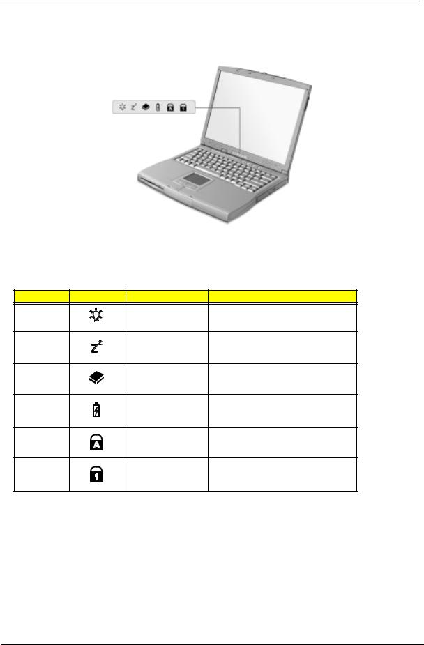
Indicators
The computer has six easy-to-read status icons on the right of the display screen.
.
The Power and Standby status icons are visible even when you close the display cover so you can see the status of the computer while the cover is closed.
# |
Icon |
Function |
Description |
1 |
|
Power |
Lights when the computer is on. |
2 |
|
Sleep |
Lights when the computer enters Standby |
|
|
|
mode and blinks when it enters into or |
|
|
|
resumes from hibernation mode. |
3 |
|
Media Activity |
Lights when the floppy drive, hard disk or |
|
|
|
AcerMedia drive is active. |
4 |
|
Battery Charge |
Lights when the battery is being charged. |
5 |
|
Caps Lock |
Lights when Caps Lock is activated. |
6 |
|
Num Lock |
Lights when Numeric Lock is activated. |
|
|
(Fn-F11) |
|
Download Free Service Manual at http://printer1.blogspot.com
10 |
Chapter 1 |
Keyboard
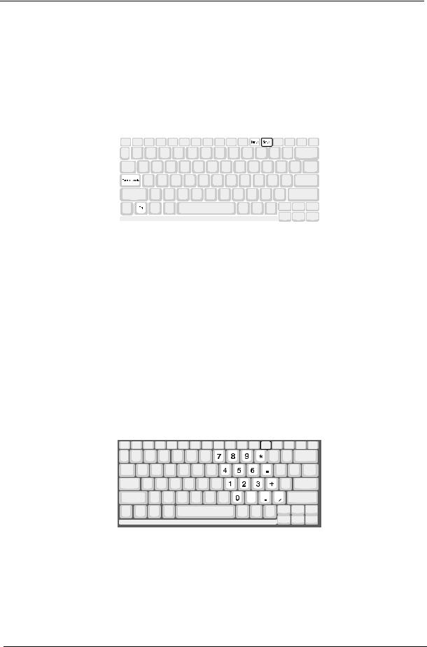
The keyboard has full-sized keys and an embedded keypad, separate cursor keys, two Windows keys and twelve function keys.
Special keys
Lock keys
The keyboard has three lock keys which you can toggle on and off.
|
|
|
|
|
|
|
|
Lock key |
Description |
||
|
|
|
|
Caps Lock |
When Caps Lock is on, all alphabetic characters typed are in uppercase. |
||
|
|
|
|
Num Lock (Fn-F11) |
When Num Lock is on, the embedded keypad is in numeric mode. The keys |
||
|
|
function as a calculator (complete with the arithmetic operators ), -, *, and /). Use |
|
|
|
this mode when you need to do a lot of numeric data entry. A better solution would |
|
|
|
be to connect an external keypad. |
|
|
|
|
|
Scroll Lock (Fn-F12) |
When Scroll Lock is on, the screen moves one line up or down when you press the |
||
|
|
up or down arrow keys respectively. Scroll Lock does not work with some |
|
|
|
applications. |
|
|
|
|
|
Embedded numeric keypad
The embedded numeric keypad functions like a desktop numeric keypad. It is indicated by small characters located on the upper right corner of the keycaps. To simplify the keyboard legend, cursor-control key symbols are not printed on the keys.
Download Free Service Manual at http://printer1.blogspot.com
Chapter 1 |
11 |
Desired access |
Num lock on |
Num lock off |
|
|
|
Number keys on embedded |
Type numbers in a normal manner. |
|
keypad |
|
|
|
|
|
Cursor-control keys on embedded |
Hold Shift while using cursor-control keys. |
Hold Fn while using cursor-control |
keypad |
|
keys. |
|
|
|
Main keyboard keys |
Hold Fn while typing letters on embedded |
Type the letters in a normal manner. |
|
keypad. |
|
|
|
|
NOTE: If an external keyboard or keypad is connected to the computer, the Num Lock feature automatically shifts from the internal keyboard to the external keyboard or keypad.
Windows keys
The keyboard has two keys that perform Windows-specific functions.
|
|
|
|
|
|
|
|
|
|
|
|
|
|
|
|
|
|
|
|
|
|
|
|
|
|
|
|
|
|
|
|
|
Keys |
|
|
|
|
Description |
|||||
|
|
|
|
|
|
|
|
|
|
|
Windows logo key |
Start button. Combinations with this key perform shortcut functions. Below |
|||||||||
!!!!!" |
|
|
|
are a few examples: |
||||||
|
|
|
|
|
||||||
|
|
|
|
|
" + Tab (Activates next taskbar button) |
|||||
|
|
|
|
|
" + E (Explores My Computer) |
|||||
|
|
|
|
|
" + F (Finds Document) |
|||||
|
|
|
|
|
" + M (Minimizes All) |
|||||
|
|
|
|
|
Shift + " + M (Undoes Minimize All |
|||||
|
|
|
|
|
" + R (Displays the Run... dialog box) |
|||||
Application key |
Opens a context menu (same as a right-click). |
|||||||||
|
|
|
|
|
|
|
|
|
|
|
|
|
|
|
|
|
|
|
|
|
|
|
|
|
|
|
|
|
|
|
|
|
|
|
|
|
|
|
|
|
|
|
|
|
|
|
|
|
|
|
|
|
|
|
|
|
|
|
|
|
|
|
|
|
|
|
|
|
|
|
|
|
|
|
|
|
|
|
|
|
|
|
|
|
|
|
|
|
|
|
|
|
|
|
|
|
|
|
Download Free Service Manual at http://printer1.blogspot.com
12 |
Chapter 1 |

Hot Keys
The computer employs hot keys or key combinations to access most of the computer’s controls like screen contrast and brightness, volume output and the BIOS Utility.
To activate hot keys, press and hold the Fn key before pressing the other key in the hot key combination.
Hot Key |
Icon |
Function |
Description |
Fn-F1 |
|
Hotkey help |
Displays a list of the hotkeys and their functions. |
Fn-F2 |
|
Setup |
Accesses the notebook configuration utility. |
Fn-F3 |
|
Power SchemeToggle |
Switches between the power management scheme |
|
|
|
used by the computer (function available if supported |
|
|
|
by operating system). |
Fn-F4 |
|
Sleep |
Puts the computer in Sleep mode. |
Fn-F5 |
|
Display toggle |
Switches display output between the display screen, |
|
|
|
external monitor (if connected) and both the display |
|
|
|
screen and external monitor. |
Fn-F6 |
|
Screen blank |
Turns the display screen backlight off to save power. |
|
|
|
Press any key to return. |
Fn-F7 |
|
Touchpad Toggle |
Turns the internal touchpad on and off. |
Fn-F8 |
|
Speaker on/off |
Turns the speakers on and off; mutes the sound. |
Fn-↑ |
|
Contrast up |
Increases the screen contrast (available only for |
|
|
|
models with HPA displays). |
Fn-↓ |
|
Contrast down |
Decreases the screen contrast (available only for |
|
|
|
models with HPA displays). |
Fn-→ |
|
Brightness up |
Increases the screen brightness. |
Fn-← |
|
Brightness down |
Decreases the screen brightness. |
Download Free Service Manual at http://printer1.blogspot.com
Chapter 1 |
13 |
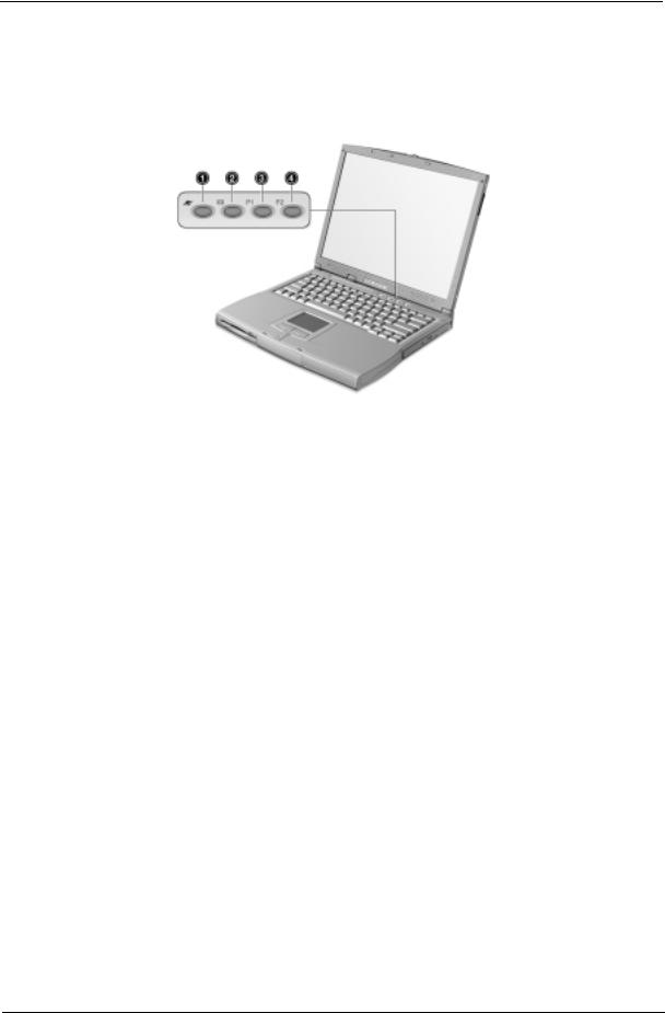
Launch Keys
Located at the top of the keyboard are four buttons. These buttons are called launch keys. They are designated as key 1, key 2, key 3 and key 4. By default, key 1 is used to launch the internet browser and key 2 is used to launch the e-mail application. Keys 3 and 4 starts the Launch Manager application. All four keys can be set by the user. To set the launch keys, run the Acer Launch Manager.
Download Free Service Manual at http://printer1.blogspot.com
14 |
Chapter 1 |
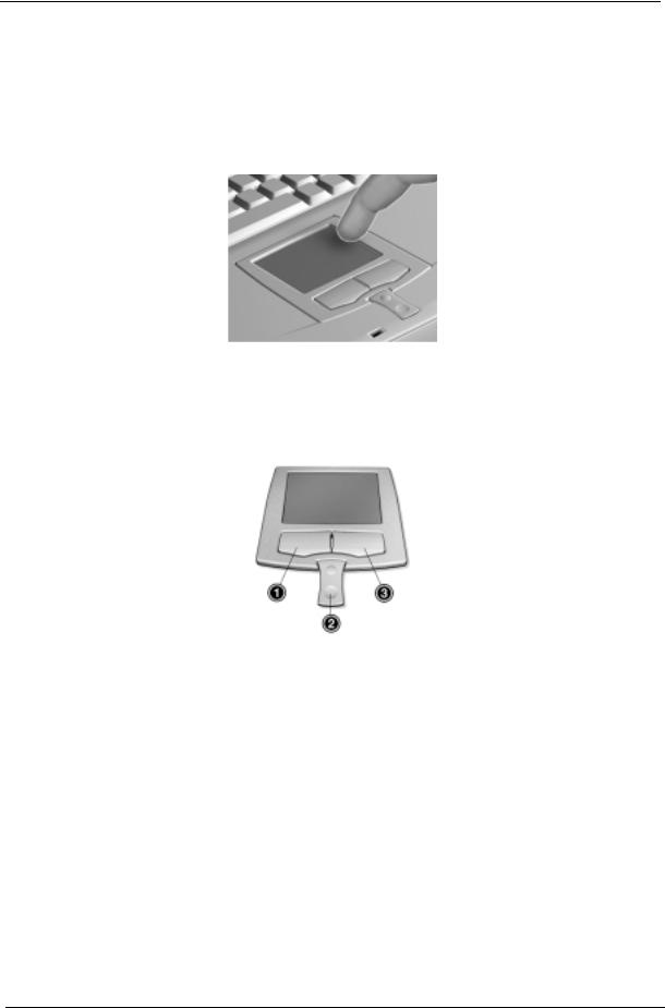
Touchpad
The built-in touchpad is a PS/2-compatible pointing device that senses movement on its surface. This means that the cursor responds as you move your finger on the surface of the touchpad. The central location on the palmrest provides optimum comfort and support.
NOTE: When using an external USB or serial mouse, you can press Fn-F7 to disable the touchpad. If you are using an external PS/2 mouse, the touchpad is automatically disabled.
Touchpad basics
The following items teach you how to use the touchpad:
1.Move your finger across the touchpad to move the cursor.
2.Press the left (1) and right (3) buttons located on the edge of the touchpad to do selection and execution functions. These two buttons are similar to the left and right buttons on amouse. Tapping on the touchpad produces similar results.
3.Use the center (2) buttons (top and bottom) to scroll up or down a page. This button mimics your cursor pressing on the right scroll bar of Windows applications.
Download Free Service Manual at http://printer1.blogspot.com
Chapter 1 |
15 |

Function |
Left Button |
Right Button |
Center Button |
Tap |
|
|
|
|
|
Execute |
Click twice quickly |
|
|
Tap twice (at the same |
|
|
|
|
speed as double- |
|
|
|
|
clicking a mouse |
|
|
|
|
button) |
|
|
|
|
|
Select |
Click once |
|
|
Tap once |
|
|
|
|
|
Drag |
Click and hold, then |
|
|
Tap twice (at the same |
|
use finger to drag the |
|
|
speed as double- |
|
cursor on the |
|
|
clicking a mouse |
|
touchpad |
|
|
button) then hold |
|
|
|
|
finger to the touchpad |
|
|
|
|
on the second tap and |
|
|
|
|
drag the cursor |
|
|
|
|
|
Access context |
|
Click once |
|
|
menu |
|
|
|
|
|
|
|
|
|
Scroll |
|
|
Click and hold the up/ |
|
|
|
|
down buttons |
|
|
|
|
|
|
NOTE: Keep your fingers dry and clean when using the touchpad. Also keep the touchpad dry and clean. The touchpad is sensitive to finger movements. Hence, the lighter the touch, the better the response. Tapping harder will not increase the touchpad’s responsiveness.
Download Free Service Manual at http://printer1.blogspot.com
16 |
Chapter 1 |

Hardware Specifications and Configurations
System Board Major Chips
Item |
Controller |
|
|
System core logic |
Intel 830 MG with VGA integrated |
|
Intel ICH3-M with Audio integrated |
|
|
Super I/O controller |
SMCLPC4L47M227 |
|
|
Audio controller |
Intel ICH |
|
|
Video controller |
Intel 830MG |
|
|
Hard disk drive controller |
Embedded in Intel ICH3-M |
|
|
Keyboard controller |
Mitsubish 38859F |
|
|
RTC |
BQ3285LFHP |
|
|
Processor
Item |
Specification |
|
|
CPU type |
Intel Mobile PIII with 512KB Cache |
|
Intel Celeron 1.06GHz processor with 256KB cache |
|
|
CPU package |
To PIII 1GHz uFCBGA2 |
|
To Celeron 1.06GHz uFPGA |
|
|
CPU core voltage |
1.7V |
|
|
CPU I/O voltage |
1.25V |
|
|
BIOS
Item |
Specification |
|
|
BIOS vendor |
Acer BIOS |
|
|
BIOS Version |
A0E0 |
|
|
BIOS ROM type |
Flash ROM |
|
|
BIOS ROM size |
512KB |
|
|
BIOS package |
32 Pin PLCC |
|
|
Supported protocols |
ACPI 2.0b, APM 1.2, PC Card 95, SM BIOS 2.3, EPP/IEEE 1284, ECP/ |
|
IEEE 1284 1.7 & 1.9, IrDA, PCI 2.1, PnP 1.0a, PS/2 keyboard and mouse, |
|
USB, VESA VGA BIOS, DDC-2B, CD-ROM bootable, Windows keyboard |
|
Microsoft Simple Boot Flag |
|
|
BIOS password control |
Set by switch, see SW setting |
|
|
Second Level Cache
Item |
Specification |
|
|
Cache controlle |
Built-in CPU |
|
|
Cache size |
128KB |
|
|
1st level cache control |
Always Enable |
|
|
2nd level cache control |
Always Enable |
|
|
Cache scheme control |
Fixed-in write back |
|
|
Download Free Service Manual at http://printer1.blogspot.com
Chapter 1 |
17 |

System Memory
Item |
Specification |
|
|
Memory controller |
Intel 830MG |
|
|
Onboard memory size |
0MB |
|
|
DIMM socket number |
2 Sockets |
|
|
Supports memory size per socket |
128/256/512 MB |
|
|
Supports maximum memory size |
1024 MB (512MB x 2) |
|
|
Supports DIMM type |
SDRAM |
|
|
Supports DIMM Speed |
133 MHz |
|
|
Supports DIMM voltage |
3.3 V |
|
|
Supports DIMM package |
144-pin so-DIM |
|
|
Memory module combinations |
You can install memory modules in any combinations as long as they |
|
match the above specifications . |
|
|
Memory Combinations
Slot 1 |
Slot 2 |
Total Memory |
|
|
|
0MB |
128MB |
128 MB |
|
|
|
128MB |
0MB |
128 MB |
|
|
|
64MB |
128MB |
192 MB |
|
|
|
128MB |
64MB |
192 MB |
|
|
|
128MB |
128MB |
256 MB |
|
|
|
256MB |
0MB |
256MB |
|
|
|
0MB |
256MB |
256MB |
|
|
|
256MB |
64MB |
320MB |
|
|
|
64MB |
256MB |
320MB |
|
|
|
256MB |
128MB |
384MB |
|
|
|
128MB |
256MB |
384MB |
|
|
|
256MB |
256MB |
512MB |
|
|
|
0MB |
512MB |
512MB |
|
|
|
512MB |
128MB |
640MB |
|
|
|
256MB |
512MB |
768MB |
|
|
|
128MB |
512MB |
640MB |
|
|
|
512MB |
256MB |
768MB |
|
|
|
256MB |
128MB |
384MB |
|
|
|
128MB |
256MB |
384MB |
|
|
|
512MB |
512MB |
1024MB |
|
|
|
0MB |
512MB |
512MB |
|
|
|
Above table lists some system memory configurations. You may combine DIMMs with various capacities to form other combinations.
NOTE: The shipping specification for DIMM combination is 64MB in slot 1.
Download Free Service Manual at http://printer1.blogspot.com
18 |
Chapter 1 |

Modem Interface
Item |
Specification |
|
|
Chipset |
Ambit MDC module with Lucent modem controller |
|
|
Fax modem data baud rate (bps) |
14.4K |
|
|
Data modem data baud rate (bps) |
56K |
|
|
Supports modem protocol |
V.90MDC |
|
|
Modem connector type |
RJ11 |
|
|
Modem connector location |
Rear side |
|
|
Floppy Disk Drive Interface
Item |
|
Specification |
|
|
|
|
|
Vendor & model name |
Mitsumi D353G W/I BEZ |
|
|
|
MCI JU-226A033 |
|
|
|
|
|
|
Floppy Disk Specifications |
|
|
|
|
|
|
|
Media recognition |
2DD (720KB |
2HD (1.2 MB, 3 mode) |
2HD (1.44MB) |
|
|
|
|
Sectors/track |
9 |
15 |
18 |
|
|
|
|
Tracks |
80 |
80 |
80 |
|
|
|
|
Data transfer rate |
1 MB |
1.6 MB |
2 MB |
(Kbit/s) |
|
|
|
|
|
|
|
Rotational speed (RPM) |
300 |
360 |
300 |
|
|
|
|
Read/write heads |
2 |
|
|
|
|
|
|
Encoding method |
MFM |
|
|
|
|
|
|
Power Requirement |
|
|
|
|
|
|
|
Input Voltage (V) |
+5V |
|
|
|
|
|
|
Hard Disk Drive Interface
Item |
|
Specification |
|
|
|
|
|
Vendor & Model Name |
IBM (IC25N010ATD) |
|
IBM (IC25N020ATD) |
|
|
|
|
Capacity (MB) |
10000 |
|
20000 |
|
|
|
|
Bytes per sector |
512 |
|
512 |
|
|
|
|
Logical heads |
16 |
|
16 |
|
|
|
|
Logical sectors |
63 |
|
63 |
|
|
|
|
Drive Format |
|
|
|
|
|
|
|
Logical cylinders |
16383 |
|
16383 |
|
|
|
|
Physical read/write heads |
2 |
|
3 |
|
|
|
|
Disk |
1 |
|
2 |
|
|
|
|
Spindle speed (RPM) |
4200RPM |
|
4200RPM |
|
|
|
|
Performance Specifications |
|
|
|
|
|
|
|
Buffer size |
512KB |
|
2MB |
|
|
|
|
Interface |
ATA-5 |
|
ATA-5 |
|
|
|
|
Data transfer rate (disk |
105-199 |
|
121-216 |
buffer, Mbytes/s) |
|
|
|
|
|
|
|
Data transfer, rate |
|
100 MB/Sec |
|
(host~buffer, Mbytes/s) |
|
|
|
|
|
|
|
DC Power Requirements |
|
|
|
|
|
|
|
Voltage tolerance |
5 +/- 5% |
|
5 +/- 5% |
|
|
|
|
Download Free Service Manual at http://printer1.blogspot.com
Chapter 1 |
19 |

CD-ROM Interface
Items |
Specification |
|
|
|
|
Vendor & Model Name |
MKE CR-177-B/D |
Mitsumi SR-243T |
|
|
|
Performance Specification |
|
|
|
|
|
Transfer rate |
CAV Mode: |
Read Sustained: |
|
775~1800 blocks/sec |
1545~3600 KB/sec |
|
Mode 1: |
Programmed I/O: |
|
1550~3600 kBytes/sec |
16.7 MB/sec Max. (Mode 0~4 |
|
Mode 2: |
Multi-word DMA: |
|
1768~4106kBytes/sec |
16.7 MB/sec Max. (Mode 0~2 |
|
|
Ultra DMA: |
|
|
33.3MB/sec Max. |
|
|
|
Access time (typ.) |
Random: 100 ms |
Random: 115 ms |
|
Full Stroke: 200 ms |
Full Stroke: 250 ms |
|
|
|
Rotation speed |
5000 rp |
5136 rp |
|
|
|
Data Buffer Capacity |
128 KB |
128 KB |
|
|
|
Interface |
IDE |
IDE |
|
|
|
Applicable disc format |
CD-Audio, CD-ROM (mode 1 and Mode |
CD/CD-ROM(12cm,8cm), CD-R, CD- |
|
2), CD-ROM XA (mode 2, form 1 an |
RW, CD-DA, CD-ROM (Mode 1, Mode2), |
|
form 2), CD-I (mode 2, form 1 and for |
CD-ROM XA (Mode 2, Form1 and For |
|
2), CD-I Ready, CD-I Bridge, Photo CD, |
2), Photo CD (Single, Multisession), |
|
CD-WO, Video CD, Enhanced Music |
Enhanced CD |
|
CD (CD Plus), CD-RW |
|
|
|
|
Loading mechanis |
Drawer with soft eject and emergency |
Drawer with soft eject and emergency |
|
eject hole |
eject hole |
|
|
|
Power Requirement |
|
|
|
|
|
Input Voltage |
+5V[DC]+/-5% |
+5V[DC]+/-5% |
|
|
|
DVD-ROM Interface
Item |
Specification |
|
|
|
|
Vendor & model name |
MKE SR-8176-BAA2 |
|
|
|
|
Performance Specification |
With CD Diskette |
With DVD Diskette |
|
|
|
Transfer rate (KB/sec) |
Average Sustained: |
DVD-5: |
|
CAV mode |
Normal Speed (1X) 11.08 Mbits/sec |
|
775~1800 blocks/sec |
CAV mode 36.67~88.64 Mbits/sec |
|
(10.3X to 24X |
DVD-9/DVD-R: |
|
1550~3600kBytes/sec (Mode 1) |
Normal Speed (1X) 11.08 Mbits/sec |
|
1768~4106 kBytes/sec (Mode 2) |
CAV mode 36.67~88.64 Mbits/sec |
|
|
|
Average Full Access time (typ.) |
Random (*1) |
DVD-5: |
|
CAV mode 110 msec typical 150 |
Random (*4) |
|
msec average max |
150 msec typical |
|
Full Stroke (*2) |
200 msec average max |
|
CAV mode 200 msec typical 260 |
Full Stroke (*5) |
|
msec average max |
300 msec typical |
|
|
400 msec average max |
|
|
DVD-9: |
|
|
Random (*7) |
|
|
170 msec typical |
|
|
230 msec average max |
|
|
Full Stroke (*8) |
|
|
340 msec typical |
|
|
470 msec average max |
|
|
|
Download Free Service Manual at http://printer1.blogspot.com
20 |
Chapter 1 |

DVD-ROM Interface
Item |
Specification |
|
|
|
|
Data Buffer Capacity |
512 kBytes |
|
|
|
|
Interface |
IDE |
|
|
|
|
Applicable disc format |
DVD: DVD-5, DVD-9, DVD-10, DVD-R (3.95G) |
|
|
CD: CD-Audio, CD-ROM (mode 1 and mode 2), CD-ROM XA (mode 2, form |
|
|
1 and form 2), CD-I (mode 2, form 1 and form 2), CD-I Ready, CD-I Bridge, |
|
|
CD-WO, CD-RW, Photo CD, Video CD, Enhanced Music CD, CD-TEXT |
|
|
|
|
Loading mechanis |
Soft eject (with emergency eject hole) |
|
|
|
|
Power Requirement |
|
|
|
|
|
Input Voltage |
+5V[DC]+/-5 |
|
|
|
|
(*1) |
Average of Data read over the whole area from 00 min. 02 sec. 00 block to 59 min. 58 sec. 74 block more |
than 2000 times including latency and layered error correction time. |
|
(*2) |
From 00 min. 02 sec. 00 block to 59 min. 58 sec. 74 block including latency and layered error correction |
time. |
|
(*3) |
Disc: MNSU-005 |
(*4) |
Average of Data read over the whole area from starting data recorded area (LBA:0) to maximum data |
recorded area (LBA:23197F), more than 2000 times including latency and layered error correction time. |
|
(*5) from starting data recorded area (LBA:0) to maximum data recorded area (LBA:23197F) including latency |
|
and layered error correction time. |
|
(*6) |
Disk: MKE-D551. |
(*7) |
Average of Data read over the whole area from starting data recorded area (LBA:0) to maximum data |
recorded area (LBA:3FA0DF), more than 2000 times including latency and layered error correction time. |
|
(*8) from starting data recorded area (LBA:0) to maximum data recorded area (LBA:3FA0DF) including latency |
|
and layered error correction time. |
|
(*9) |
Disk: ODSC-PARA |
Audio Interface |
|
Item |
Specification |
|
|
Audio Controller |
Cirrus Logic CS4299-XQ |
|
|
Audio onboard or optional |
Built-in |
|
|
Mono or Stereo |
Stereo |
|
|
Resolution |
20 bit stereo Digital to Analog converter |
|
18 bit stereo Analog to Digital converter |
|
|
Compatibility |
Microsoft PC98/PC99, AC97 2.1 |
|
|
Mixed sound source |
Line-in, CD, Video, AUX |
|
|
Voice channel |
8/16 bit, mono/stereo |
|
|
Sampling rate |
44.1 KHz |
|
|
Internal microphone |
Yes |
|
|
Internal speaker / Quantity |
Yes |
|
|
Supports PnP DMA channel |
DMA channel 0 |
|
DMA channel 1 |
|
|
Supports PnP IRQ |
IRQ3, IRQ5, IRQ7, IRQ9, IRQ10, IRQ11 |
|
|
Video Interface
Item |
Specification |
|
|
Vendor & Model Name |
Intel 830MG |
|
|
Chip voltage |
Core / 2.5V, 1.5V, 1.8V |
|
|
Supports ZV (Zoomed Video) port |
NO |
|
|
Graph interface |
2X AGP (Accelerated Graphic Port) Bus |
|
|
Download Free Service Manual at http://printer1.blogspot.com
Chapter 1 |
21 |
Loading...