


 Loading...
Aspire 5742/5742G/5742Z/5742ZG Series Service Guide
Service guide files and updates are available on the ACER/CSD web; for more information, please refer to http://csd.acer.com.tw
PRINTED IN TAIWAN

Revision History
Please refer to the table below for the updates made on Aspire 5741/5741G service guides.
Date |
Chapter |
Updates |
|
|
|
|
|
|
|
|
|
|
|
|
II

Copyright
Copyright © 2010 by Acer Incorporated. All rights reserved. No part of this publication may be reproduced, transmitted, transcribed, stored in a retrieval system, or translated into any language or computer language, in any form or by any means, electronic, mechanical, magnetic, optical, chemical, manual or otherwise, without the prior written permission of Acer Incorporated.
Disclaimer
The information in this guide is subject to change without notice.
Acer Incorporated makes no representations or warranties, either expressed or implied, with respect to the contents hereof and specifically disclaims any warranties of merchantability or fitness for any particular purpose. Any Acer Incorporated software described in this manual is sold or licensed "as is". Should the programs prove defective following their purchase, the buyer (and not Acer Incorporated, its distributor, or its dealer) assumes the entire cost of all necessary servicing, repair, and any incidental or consequential damages resulting from any defect in the software.
Acer is a registered trademark of Acer Corporation. Intel is a registered trademark of Intel Corporation.
Other brand and product names are trademarks and/or registered trademarks of their respective holders.
III

Conventions
The following conventions are used in this manual:
SCREEN MESSAGES |
Denotes actual messages that appear |
|
on screen. |
|
|
NOTE |
Gives bits and pieces of additional |
|
information related to the current |
|
topic. |
|
|
WARNING |
Alerts you to any damage that might |
|
result from doing or not doing specific |
|
actions. |
|
|
CAUTION |
Gives precautionary measures to |
|
avoid possible hardware or software |
|
problems. |
|
|
IMPORTANT |
Reminds you to do specific actions |
|
relevant to the accomplishment of |
|
procedures. |
|
|
NOTE: This symbol where placed in the Service Guide designates a component that should be recycled according to the local regulations.
IV

Preface
Before using this information and the product it supports, please read the following general information.
1.This Service Guide provides you with all technical information relating to the BASIC CONFIGURATION decided for Acer's "global" product offering. To better fit local market requirements and enhance product competitiveness, your regional office MAY have decided to extend the functionality of a machine (e.g. add-on card, modem, or extra memory capability). These LOCALIZED FEATURES will NOT be covered in this generic service guide. In such cases, please contact your regional offices or the responsible personnel/channel to provide you with further technical details.
2.Please note WHEN ORDERING FRU PARTS, that you should check the most up-to-date information available on your regional web or channel. If, for whatever reason, a part number change is made, it will not be noted in the printed Service Guide. For ACER-AUTHORIZED SERVICE PROVIDERS, your Acer office may have a DIFFERENT part number code to those given in the FRU list of this printed Service Guide. You MUST use the list provided by your regional Acer office to order FRU parts for repair and service of customer machines.
V

VI

Table of Contents
System Specifications |
1 |
Features . . . . . . . . . . . . . . . . . . . . . . . . . . . . . . . . . . . . . . . . . . . . . . . . . . . . . . . . . . . .1 System Block Diagram . . . . . . . . . . . . . . . . . . . . . . . . . . . . . . . . . . . . . . . . . . . . . . . . .6 UMA . . . . . . . . . . . . . . . . . . . . . . . . . . . . . . . . . . . . . . . . . . . . . . . . . . . . . . . . . . .6 Discrete (nVidia) . . . . . . . . . . . . . . . . . . . . . . . . . . . . . . . . . . . . . . . . . . . . . . . . . .7 Discrete (ATI) . . . . . . . . . . . . . . . . . . . . . . . . . . . . . . . . . . . . . . . . . . . . . . . . . . . .8 Your Acer Notebook tour . . . . . . . . . . . . . . . . . . . . . . . . . . . . . . . . . . . . . . . . . . . . . . .9 Top View . . . . . . . . . . . . . . . . . . . . . . . . . . . . . . . . . . . . . . . . . . . . . . . . . . . . . . . .9 Rear view . . . . . . . . . . . . . . . . . . . . . . . . . . . . . . . . . . . . . . . . . . . . . . . . . . . . . .10 Left View . . . . . . . . . . . . . . . . . . . . . . . . . . . . . . . . . . . . . . . . . . . . . . . . . . . . . . .11 Right View . . . . . . . . . . . . . . . . . . . . . . . . . . . . . . . . . . . . . . . . . . . . . . . . . . . . . .12 Base view . . . . . . . . . . . . . . . . . . . . . . . . . . . . . . . . . . . . . . . . . . . . . . . . . . . . . .13 Indicators . . . . . . . . . . . . . . . . . . . . . . . . . . . . . . . . . . . . . . . . . . . . . . . . . . . . . .14 Touch Pad Basics . . . . . . . . . . . . . . . . . . . . . . . . . . . . . . . . . . . . . . . . . . . . . . . .15 Using the Keyboard . . . . . . . . . . . . . . . . . . . . . . . . . . . . . . . . . . . . . . . . . . . . . . . . . .16 Lock Keys and embedded numeric keypad . . . . . . . . . . . . . . . . . . . . . . . . . . . .16 Windows Keys . . . . . . . . . . . . . . . . . . . . . . . . . . . . . . . . . . . . . . . . . . . . . . . . . .17 Hot Keys . . . . . . . . . . . . . . . . . . . . . . . . . . . . . . . . . . . . . . . . . . . . . . . . . . . . . . .18
Hardware Specifications and Configurations . . . . . . . . . . . . . . . . . . . . . . . . . . . . . . .19
System Utilities |
31 |
BIOS Setup Utility . . . . . . . . . . . . . . . . . . . . . . . . . . . . . . . . . . . . . . . . . . . . . . . . . . . .31 Navigating the BIOS Utility . . . . . . . . . . . . . . . . . . . . . . . . . . . . . . . . . . . . . . . . .31 Aspire 5742/5742G/5742Z/5742ZG BIOS . . . . . . . . . . . . . . . . . . . . . . . . . . . . . . . . .32 Information . . . . . . . . . . . . . . . . . . . . . . . . . . . . . . . . . . . . . . . . . . . . . . . . . . . . .32 Main . . . . . . . . . . . . . . . . . . . . . . . . . . . . . . . . . . . . . . . . . . . . . . . . . . . . . . . . . .33 Security . . . . . . . . . . . . . . . . . . . . . . . . . . . . . . . . . . . . . . . . . . . . . . . . . . . . . . . .34 Boot . . . . . . . . . . . . . . . . . . . . . . . . . . . . . . . . . . . . . . . . . . . . . . . . . . . . . . . . . . .37 Exit . . . . . . . . . . . . . . . . . . . . . . . . . . . . . . . . . . . . . . . . . . . . . . . . . . . . . . . . . . .38 BIOS Flash Utilities . . . . . . . . . . . . . . . . . . . . . . . . . . . . . . . . . . . . . . . . . . . . . . . . . . .39 DOS Flash Utility . . . . . . . . . . . . . . . . . . . . . . . . . . . . . . . . . . . . . . . . . . . . . . . . .40 WinFlash Utility . . . . . . . . . . . . . . . . . . . . . . . . . . . . . . . . . . . . . . . . . . . . . . . . . .41 Remove HDD/BIOS Password Utilities . . . . . . . . . . . . . . . . . . . . . . . . . . . . . . . . . . . .42
Machine Disassembly and Replacement |
47 |
Disassembly Requirements . . . . . . . . . . . . . . . . . . . . . . . . . . . . . . . . . . . . . . . . . . . |
.47 |
Pre-disassembly Instructions . . . . . . . . . . . . . . . . . . . . . . . . . . . . . . . . . . . . . . |
.48 |
Disassembly Process . . . . . . . . . . . . . . . . . . . . . . . . . . . . . . . . . . . . . . . . . . . . . |
49 |
External Module Disassembly Process . . . . . . . . . . . . . . . . . . . . . . . . . . . . . . . . . . . |
50 |
External Modules Disassembly Flowchart . . . . . . . . . . . . . . . . . . . . . . . . . . . . . |
50 |
Removing the Battery Pack . . . . . . . . . . . . . . . . . . . . . . . . . . . . . . . . . . . . . . . . |
51 |
Removing the SD Dummy Card . . . . . . . . . . . . . . . . . . . . . . . . . . . . . . . . . . . . . |
52 |
Removing the ODD Module . . . . . . . . . . . . . . . . . . . . . . . . . . . . . . . . . . . . . . . . |
53 |
Removing the Logic Lower Door . . . . . . . . . . . . . . . . . . . . . . . . . . . . . . . . . . . . . |
55 |
Removing the 3G Cover (Discrete Only) . . . . . . . . . . . . . . . . . . . . . . . . . . . . . . |
56 |
Removing the RTC Battery (UMA Only) . . . . . . . . . . . . . . . . . . . . . . . . . . . . . . . |
57 |
Removing the DIMM Module . . . . . . . . . . . . . . . . . . . . . . . . . . . . . . . . . . . . . . . |
59 |
Removing the WLAN Module . . . . . . . . . . . . . . . . . . . . . . . . . . . . . . . . . . . . . . . |
60 |
Removing the HDD module Module . . . . . . . . . . . . . . . . . . . . . . . . . . . . . . . . . . |
62 |
Removing the Keyboard . . . . . . . . . . . . . . . . . . . . . . . . . . . . . . . . . . . . . . . . . . . |
64 |
Main Unit Disassembly Process . . . . . . . . . . . . . . . . . . . . . . . . . . . . . . . . . . . . . . . . . |
66 |
Main Unit Disassembly Flowchart . . . . . . . . . . . . . . . . . . . . . . . . . . . . . . . . . . . . |
66 |
Removing the Upper Cover . . . . . . . . . . . . . . . . . . . . . . . . . . . . . . . . . . . . . . . . |
67 |
Removing the Speaker Module . . . . . . . . . . . . . . . . . . . . . . . . . . . . . . . . . . . . . . |
72 |
VII

Table of Contents
Removing the Power Board . . . . . . . . . . . . . . . . . . . . . . . . . . . . . . . . . . . . . . . .74 Removing the Touch Pad FFC . . . . . . . . . . . . . . . . . . . . . . . . . . . . . . . . . . . . . .76 Removing the Card Reader Module (Discrete Only) . . . . . . . . . . . . . . . . . . . . .78 Removing the USB Board . . . . . . . . . . . . . . . . . . . . . . . . . . . . . . . . . . . . . . . . . .80
Removing the Bluetooth Board . . . . . . . . . . . . . . . . . . . . . . . . . . . . . . . . . . . |
. .82 |
Removing the ODD Connector Board (UMA Only) . . . . . . . . . . . . . . . . . . . . . |
. .84 |
Removing the Mainboard . . . . . . . . . . . . . . . . . . . . . . . . . . . . . . . . . . . . . . . . . |
.85 |
Removing the Thermal Module . . . . . . . . . . . . . . . . . . . . . . . . . . . . . . . . . . . . . |
.89 |
Removing the CPU . . . . . . . . . . . . . . . . . . . . . . . . . . . . . . . . . . . . . . . . . . . . . . |
.91 |
Removing the LCD Module . . . . . . . . . . . . . . . . . . . . . . . . . . . . . . . . . . . . . . . . |
.92 |
Removing the DC-In Assembly . . . . . . . . . . . . . . . . . . . . . . . . . . . . . . . . . . . . . |
.96 |
LCD Module Disassembly Process . . . . . . . . . . . . . . . . . . . . . . . . . . . . . . . . . . . . . |
.97 |
LCD Module Disassembly Flowchart . . . . . . . . . . . . . . . . . . . . . . . . . . . . . . . . |
.97 |
Removing the LCD Bezel . . . . . . . . . . . . . . . . . . . . . . . . . . . . . . . . . . . . . . . . . |
.98 |
Removing the CCD Module . . . . . . . . . . . . . . . . . . . . . . . . . . . . . . . . . . . . . . . |
100 |
Removing the Inverter Module (LCD Only) . . . . . . . . . . . . . . . . . . . . . . . . . . . . |
101 |
Removing the LCD/LED Panel . . . . . . . . . . . . . . . . . . . . . . . . . . . . . . . . . . . . . |
104 |
Removing the LCD Brackets . . . . . . . . . . . . . . . . . . . . . . . . . . . . . . . . . . . . . . . |
106 |
Removing the LVDS Cable . . . . . . . . . . . . . . . . . . . . . . . . . . . . . . . . . . . . . . . . |
107 |
Removing the Microphone Cable . . . . . . . . . . . . . . . . . . . . . . . . . . . . . . . . . . . |
108 |
Removing the Antennas . . . . . . . . . . . . . . . . . . . . . . . . . . . . . . . . . . . . . . . . . . |
110 |
LCD Module Reassembly Procedure . . . . . . . . . . . . . . . . . . . . . . . . . . . . . . . . . . . . |
111 |
Replacing the Antennas . . . . . . . . . . . . . . . . . . . . . . . . . . . . . . . . . . . . . . . . . . |
111 |
Replacing the Microphone Cable . . . . . . . . . . . . . . . . . . . . . . . . . . . . . . . . . . . |
112 |
Replacing the LVDS Cable . . . . . . . . . . . . . . . . . . . . . . . . . . . . . . . . . . . . . . . . |
114 |
Replacing the LCD Brackets . . . . . . . . . . . . . . . . . . . . . . . . . . . . . . . . . . . . . . . |
115 |
Replacing the LCD/LED Panel . . . . . . . . . . . . . . . . . . . . . . . . . . . . . . . . . . . . . |
116 |
Replacing the Inverter Board . . . . . . . . . . . . . . . . . . . . . . . . . . . . . . . . . . . . . . |
117 |
Replacing the CCD Module . . . . . . . . . . . . . . . . . . . . . . . . . . . . . . . . . . . . . . . |
119 |
Replacing the LCD Bezel . . . . . . . . . . . . . . . . . . . . . . . . . . . . . . . . . . . . . . . . . |
120 |
Main Module Assembly Procedure . . . . . . . . . . . . . . . . . . . . . . . . . . . . . . . . . . . . . . |
121 |
Replacing the DC-In Assembly . . . . . . . . . . . . . . . . . . . . . . . . . . . . . . . . . . . . . |
121 |
Replacing the LCD Module . . . . . . . . . . . . . . . . . . . . . . . . . . . . . . . . . . . . . . . . |
122 |
Replacing the CPU . . . . . . . . . . . . . . . . . . . . . . . . . . . . . . . . . . . . . . . . . . . . . . |
125 |
Replacing the Thermal Module . . . . . . . . . . . . . . . . . . . . . . . . . . . . . . . . . . . . . |
127 |
Replacing the Mainboard . . . . . . . . . . . . . . . . . . . . . . . . . . . . . . . . . . . . . . . . . |
129 |
Replacing the ODD Connector Board (UMA Only) . . . . . . . . . . . . . . . . . . . . . . |
133 |
Replacing the Bluetooth Board . . . . . . . . . . . . . . . . . . . . . . . . . . . . . . . . . . . . . |
134 |
Replacing the USB Board . . . . . . . . . . . . . . . . . . . . . . . . . . . . . . . . . . . . . . . . . |
135 |
Replacing the Card Reader Board (Discrete Only) . . . . . . . . . . . . . . . . . . . . . . |
137 |
Replacing the Touchpad FFC . . . . . . . . . . . . . . . . . . . . . . . . . . . . . . . . . . . . . . |
139 |
Replacing the Power Board . . . . . . . . . . . . . . . . . . . . . . . . . . . . . . . . . . . . . . . |
140 |
Replacing the Speaker Module . . . . . . . . . . . . . . . . . . . . . . . . . . . . . . . . . . . . . |
141 |
Replacing the Upper Cover . . . . . . . . . . . . . . . . . . . . . . . . . . . . . . . . . . . . . . . . |
142 |
Replacing the RTC Battery (UMA Only) . . . . . . . . . . . . . . . . . . . . . . . . . . . . . . |
146 |
Replacing the HDD Module . . . . . . . . . . . . . . . . . . . . . . . . . . . . . . . . . . . . . . . |
147 |
Replacing the WLAN Module . . . . . . . . . . . . . . . . . . . . . . . . . . . . . . . . . . . . . . |
149 |
Replacing the DIMM Modules . . . . . . . . . . . . . . . . . . . . . . . . . . . . . . . . . . . . . . |
151 |
Replacing the 3G Cover (Discrete Only) . . . . . . . . . . . . . . . . . . . . . . . . . . . . . . |
152 |
Replacing the Lower Logic Door . . . . . . . . . . . . . . . . . . . . . . . . . . . . . . . . . . . . |
153 |
Replacing the ODD Module . . . . . . . . . . . . . . . . . . . . . . . . . . . . . . . . . . . . . . . |
154 |
Replacing the Keyboard . . . . . . . . . . . . . . . . . . . . . . . . . . . . . . . . . . . . . . . . . . |
156 |
Replacing the SD Dummy Card . . . . . . . . . . . . . . . . . . . . . . . . . . . . . . . . . . . . |
157 |
Replacing the Battery . . . . . . . . . . . . . . . . . . . . . . . . . . . . . . . . . . . . . . . . . . . . |
158 |
VIII

Table of Contents
Troubleshooting |
159 |
Common Problems . . . . . . . . . . . . . . . . . . . . . . . . . . . . . . . . . . . . . . . . . . . . . . . . . .159 Power On Issue . . . . . . . . . . . . . . . . . . . . . . . . . . . . . . . . . . . . . . . . . . . . . . . .160 No Display Issue . . . . . . . . . . . . . . . . . . . . . . . . . . . . . . . . . . . . . . . . . . . . . . . .161 Random Loss of BIOS Settings . . . . . . . . . . . . . . . . . . . . . . . . . . . . . . . . . . . .162 LCD Failure . . . . . . . . . . . . . . . . . . . . . . . . . . . . . . . . . . . . . . . . . . . . . . . . . . . .163 Internal Keyboard Failure . . . . . . . . . . . . . . . . . . . . . . . . . . . . . . . . . . . . . . . . .163 Touch Pad Failure . . . . . . . . . . . . . . . . . . . . . . . . . . . . . . . . . . . . . . . . . . . . . . .164 Internal Speaker Failure . . . . . . . . . . . . . . . . . . . . . . . . . . . . . . . . . . . . . . . . . .164 Microphone Record Failure . . . . . . . . . . . . . . . . . . . . . . . . . . . . . . . . . . . . . . . .166 USB Failure (Right side) . . . . . . . . . . . . . . . . . . . . . . . . . . . . . . . . . . . . . . . . . .167 HDD Not Operating Correctly . . . . . . . . . . . . . . . . . . . . . . . . . . . . . . . . . . . . . .168 ODD Failure . . . . . . . . . . . . . . . . . . . . . . . . . . . . . . . . . . . . . . . . . . . . . . . . . . .169 Wireless Function Failure . . . . . . . . . . . . . . . . . . . . . . . . . . . . . . . . . . . . . . . . .172 Bluetooth Function Test Failure . . . . . . . . . . . . . . . . . . . . . . . . . . . . . . . . . . . .172 2 in 1 card Function Test Failure . . . . . . . . . . . . . . . . . . . . . . . . . . . . . . . . . . .173 Thermal Unit Failure . . . . . . . . . . . . . . . . . . . . . . . . . . . . . . . . . . . . . . . . . . . . .173 External Mouse Failure . . . . . . . . . . . . . . . . . . . . . . . . . . . . . . . . . . . . . . . . . . .174 Cosmetic Failure . . . . . . . . . . . . . . . . . . . . . . . . . . . . . . . . . . . . . . . . . . . . . . . .174 Other Failures . . . . . . . . . . . . . . . . . . . . . . . . . . . . . . . . . . . . . . . . . . . . . . . . . .175
Intermittent Problems . . . . . . . . . . . . . . . . . . . . . . . . . . . . . . . . . . . . . . . . . . . . . . . .176 Undetermined Problems . . . . . . . . . . . . . . . . . . . . . . . . . . . . . . . . . . . . . . . . . . . . . .176 Post Codes . . . . . . . . . . . . . . . . . . . . . . . . . . . . . . . . . . . . . . . . . . . . . . . . . . . . . . . .177
Jumper and Connector Locations |
183 |
Top View . . . . . . . . . . . . . . . . . . . . . . . . . . . . . . . . . . . . . . . . . . . . . . . . . . . . . |
.183 |
Bottom View . . . . . . . . . . . . . . . . . . . . . . . . . . . . . . . . . . . . . . . . . . . . . . . . . . |
.186 |
USB/B Board . . . . . . . . . . . . . . . . . . . . . . . . . . . . . . . . . . . . . . . . . . . . . . . . . . |
.189 |
Power Board . . . . . . . . . . . . . . . . . . . . . . . . . . . . . . . . . . . . . . . . . . . . . . . . . . |
.190 |
CR/B Board . . . . . . . . . . . . . . . . . . . . . . . . . . . . . . . . . . . . . . . . . . . . . . . . . . . |
.193 |
ODD Board . . . . . . . . . . . . . . . . . . . . . . . . . . . . . . . . . . . . . . . . . . . . . . . . . . . |
.194 |
Clearing Password Check and BIOS Recovery . . . . . . . . . . . . . . . . . . . . . . . . . . . |
.195 |
Clearing Password Check . . . . . . . . . . . . . . . . . . . . . . . . . . . . . . . . . . . . . . . . |
.195 |
Clear CMOS Jumper . . . . . . . . . . . . . . . . . . . . . . . . . . . . . . . . . . . . . . . . . . . . |
.195 |
BIOS Recovery by Crisis Disk . . . . . . . . . . . . . . . . . . . . . . . . . . . . . . . . . . . . |
.197 |
FRU (Field Replaceable Unit) List |
199 |
Aspire Exploded Diagrams . . . . . . . . . . . . . . . . . . . . . . . . . . . . . . . . . . . . . . . . . . . .200
Main Assembly . . . . . . . . . . . . . . . . . . . . . . . . . . . . . . . . . . . . . . . . . . . . . . . . .200
Lower Cover . . . . . . . . . . . . . . . . . . . . . . . . . . . . . . . . . . . . . . . . . . . . . . . . . . .202
LCD Assembly . . . . . . . . . . . . . . . . . . . . . . . . . . . . . . . . . . . . . . . . . . . . . . . . .203
LED Assembly . . . . . . . . . . . . . . . . . . . . . . . . . . . . . . . . . . . . . . . . . . . . . . . . .204
Aspire FRU List . . . . . . . . . . . . . . . . . . . . . . . . . . . . . . . . . . . . . . . . . . . . . . . . . . . . .205
Screw List . . . . . . . . . . . . . . . . . . . . . . . . . . . . . . . . . . . . . . . . . . . . . . . . . . . . . . . . .229
Model Definition and Configuration |
231 |
Aspire 5742/5742G . . . . . . . . . . . . . . . . . . . . . . . . . . . . . . . . . . . . . . . . . . . . . |
.231 |
Aspire 5742Z/5742ZG . . . . . . . . . . . . . . . . . . . . . . . . . . . . . . . . . . . . . . . . . . . |
.257 |
Test Compatible Components |
273 |
Online Support Information |
279 |
Index |
281 |
IX

Table of Contents
X
Chapter 1
System Specifications
Features
Below is a brief summary of the computer’s many features:
NOTE: Items denoted with an (*) are only available for selected models.
Operating System
•Genuine Windows® 7 Home Premium 64-bit2
•Genuine Windows® 7 Home Basic 64-bit2
CPU and chipset
•Mobile Intel® HM55 Express Chipset
5742, 5742G
•Intel® Core™ i5-450M/i5-460M/i5-540M/i5-560M/i5-580M processor (3 MB L3 cache, 2.40/2.53/ 2.53/2.67/2.67 GHz with Turbo Boost up to 2.66/2.80/3.06/3.20/3.33 GHz, DDR3 1066 MHz, 35 W), supporting Intel® 64 architecture, Intel® Smart Cache
•Intel® Core™ i3-350M/i3-370M/i3-380M processor (3 MB L3 cache, 2.26/2.40/2.53 GHz, DDR3 1066 MHz, 35 W), supporting Intel® 64 architecture, Intel® Smart Cache
5742Z, 5742ZG
•Intel® Pentium® processor P6100/P6200 (3 MB L3 cache, 2/2.13 GHz, DDR3 1066 MHz, 35 W), supporting Intel® 64 architecture, Intel® Smart Cache
System Memory
•Dual-channel DDR3 SDRAM support:
• Up to 4 GB of DDR3 system memory, upgradable to 8 GB using two soDIMM modules
Display
•15.6" HD 1366 x 768 pixel resolution, high-brightness (200-nit) Acer CineCrystal™ TFT LCD
•16:9 aspect ratio
Audio
•Built-in mono speaker
•High-definition audio support
•MS-Sound compatible
•Built-in microphone
Chapter 1 |
1 |

Graphics
•Dual independent display support
•16.7 million colors
•External resolution / refresh rates:
•VGA port up to 2560 x 1600: 60 Hz
•HDMI™ port up to 1920 x 1080: 60 Hz
•MPEG-2/DVD decoding
•WMV9 (VC-1) and H.264 (AVC) decoding
•HDMI™ (High-Definition Multimedia Interface) with HDCP (High-bandwidth Digital Content Protection) support
5742, 5742Z
•Intel® HD Graphics with 128 MB of dedicated system memory, supporting Microsoft® DirectX® 10
5742G, 5742ZG
•NVIDIA® GeForce® GT 420M with 1024 MB of dedicated DDR3 VRAM, supporting NVIDIA® CUDA™, PhysX™, PureVideo® HD technology, OpenEXR High Dynamic-Range (HDR) technology, Shader Model 5.0, Microsoft® DirectX® 11
•ATI Mobility Radeon™ HD 5470 with 512 MB of dedicated DDR3 VRAM, supporting Unified Video Decoder (UVD), OpenEXR High Dynamic-Range (HDR) technology, Shader Model 5.0, Microsoft® DirectX® 11, OpenGL® 3.1, OpenCL™ 1.1
Storage
Hard disk drive:
•160/250/320/500/640/750 GB or larger
2-in-1 card reader, supporting:
•Secure Digital™ (SD) Card, MultiMediaCard™ (MMC)
Optical Media Drive
•8X DVD-Super Multi double-layer drive:
•Read: 24X CD-ROM, 24X CD-R, 24X CD-RW, 8X DVD-ROM, 8X DVD-R, 8X DVD+R, 6X DVD-ROM DL, 6X DVD-R DL, 6X DVD+R DL, 6X DVD-RW, 6X DVD+RW, 5X DVD-RAM
•Write: 24X CD-R, 16X CD-RW, 8X DVD-R, 8X DVD+R, 4X DVD-R DL, 4X DVD+R DL, 6X DVD-RW, 8X DVD+RW, 5X DVD-RAM
5742G,5742ZG
•4X Blu-ray Disc™ / DVD-Super Multi double-layer drive:
•Read: 24X CD-ROM, 24X CD-R, 24X CD-RW, 8X DVD-ROM, 8X DVD-R, 8X DVD+R, 8X DVD-ROM DL, 6X DVD-R DL, 6X DVD+R DL, 8X DVD-RW, 8X DVD+RW, 5X DVD-RAM, 4X BD-ROM, 4X BD-R, 2X BD-RE, 4X BD-ROM DL, 4X BD-R DL, 2X BD-RE DL
•Write: 24X CD-R, 16X CD-RW, 8X DVD-R, 8X DVD+R, 6X DVD-RW, 6X DVD+RW, 5X DVDRAM, 4X DVD+R DL, 4X DVD-R DL
Webcam
•Acer Video Conference featuring:
• Acer Crystal Eye webcam with 1280 x 1024 resolution
2 |
Chapter 1 |

Wireless and networking
WLAN:
•Acer InviLink™ Nplify™ 802.11b/g/n Wi-Fi CERTIFIED™
•Acer InviLink™ 802.11b/g Wi-Fi CERTIFIED™
•Supporting Acer SignalUp™ wireless technology
WPAN:
•Bluetooth® 3.0+HS
•Bluetooth® 2.1+EDR
LAN: Gigabit Ethernet, Wake-on-LAN ready
Privacy control
•BIOS user, supervisor, HDD passwords
•Kensington lock slot
Power adapter and battery
•ACPI 3.0 CPU power management standard: supports Stand-by and Hibernation power-saving modes
Battery
•48.8 W 4400 mAh 6-cell Li-ion standard battery pack
•ENERGY STAR®
•5742, 5742Z
•Battery life: 3.5 hours
•5742G, 5742ZG
•Battery life: 3 hours
Power adapter
•3-pin 65 W AC adapter:
•108 (W) x 46 (D) x 29.5 (H) mm (4.25 x 1.81 x 1.16 inches)
•225 g (0.49 lbs.) with 180 cm DC cable
•5742G, 5742ZG
•3-pin 90 W AC adapter:
•133 (W) x 59 (D) x 31 (H) mm (5.23 x 2.32 x 1.22 inches)
•390 g (0.86 lbs.) with 180 cm DC cable
•Acer QuicCharge™ technology:
•80% charge in 1 hour
•2-hour rapid charge system-off
Chapter 1 |
3 |

Dimensions and weight
Dimensions:
•381 (W) x 253 (D) x 25/34 (H) mm (15 x 9.96 x 0.98/1.33 inches)
Weight:
•2.6 kg (5.74 lbs.) with 6-cell battery pack
Input and control
Keyboard:
•103-/104-/107-key Acer FineTip keyboard with independent standard numeric keypad, international language support
Touchpad:
•Multi-gesture touchpad, supporting two-finger scroll, pinch, rotate, flip
Media keys:
•Media control keys (printed on keyboard): play/pause, stop, previous, next, volume up, volume down
Input and output
•2-in-1 card reader (SD™, MMC)
•Three USB 2.0 ports
•HDMI™ port with HDCP support
•External display (VGA) port
•Headphone/speaker/line-out jack
•Microphone-in jack
•Ethernet (RJ-45) port
•DC-in jack for AC adapter
Optional items
•1/2/4 GB DDR3 soDIMM module
•6-cell Li-ion battery pack
•3-pin 65 W AC adapter
•External USB 56K modem
5742G, 5742ZG
•3-pin 90 W AC adapter
Warranty
•One-year International Travelers Warranty (ITW)
4 |
Chapter 1 |

Software
Productivity
•Acer Backup Manager
•Acer ePower Management
•Acer eRecovery Management
•Adobe® Flash® Player 10
•Adobe® Reader® 9.1
•eSobi™
•Google Toolbar™
•Microsoft® Office 2010 preloaded (purchase a product key to activate)
•Microsoft® Office Starter 2010
•Norton™ Online Backup
Security
•McAfee® Internet Security Suite Trial
•MyWinLocker®
Multimedia
•Cyberlink® PowerDVD™
•NTI Media Maker™
Gaming
•Oberon GameZone (except US, Canada, Hong Kong, Korea)
•WildTangent® (US, Canada only)
Communication and ISP
•Acer Crystal Eye
•Microsoft® Silverlight™
•Skype™
•Windows Live™ Essentials - Wave 3.2 (Mail, Photo Gallery, Live™ Messenger, Movie Maker, Writer)
Web links and utilities
•Acer Accessory Store (Belgium, France, Germany, Italy, Netherlands, Spain, Sweden, UK only)
•Acer Identity Card
•Acer Registration
•Acer Updater
•eBay® shortcut 2009
•Netflix shortcut (US only)
Chapter 1 |
5 |

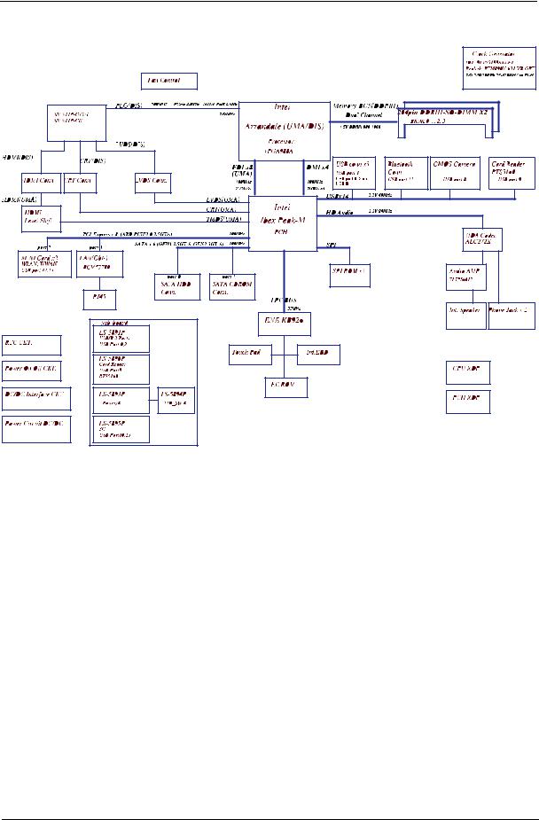
System Block Diagram
UMA
|
|
|
|
|
|
|
|
|
|
|
|
|
|
|
Fan Control |
|
|
|
|
|
|
|
|
Intel |
|
|
Memory BUS(DDRIII) |
|
|
|
|
|
|
|
|
|
|
|
|
|
|
|
|
|
|
|
|
||||||||||||||
|
|
|
|
|
|
|
|
|
|
|
|
|
|
|
|
|
|
|
|
|
|
|
Arrandale (UMA) |
|
|
|
|
Dual Channel |
204pin DDRIII-SO-DIMM X2 |
|
|
|
|
|
|
||||||||||||||||||||||||||
|
|
|
|
|
|
|
|
|
|
|
|
|
|
|
|
|
|
|
|
|
|
|
|
|
|
|
|
|
|
|
|
|
|
|
BANK 0, 1, 2, 3 |
|
|
|
|
|
|
|
|
|
|||||||||||||||||
|
|
|
|
|
|
|
|
|
|
|
|
|
|
|
|
|
|
|
|
|
|
|
|
|
1.5V DDRIII 800/1066/1333 |
|
|
|
|
|
|
|
|
|
|
||||||||||||||||||||||||||
|
|
|
|
|
|
|
|
|
|
|
|
|
|
|
|
|
|
|
|
|
|
|
|
|
Processor |
|
|
|
|
|
|
|
|
|
|
|
|
|
|
|
|
|
|
|
|
|
|
|
|||||||||||||
|
|
|
|
|
|
|
|
|
|
|
|
|
|
|
|
|
|
|
|
|
|
|
|
|
|
|
|
6.4G/8.5G/10.6G |
|
|
|
|
|
|
|
|
|
|
|
|
|
|
|
|
|
|
|
|
|||||||||||||
|
|
|
|
|
|
|
|
|
|
|
|
|
|
|
|
|
|
|
|
|
|
|
|
|
rPGA988A |
|
|
|
100M/133M/166M(CFD) |
|
|
|
|
|
|
|
|
|
|
|
|
|
|
|
|
|
|
|
|
||||||||||||
|
|
|
|
|
|
|
|
|
|
|
|
|
|
|
|
|
|
|
|
|
|
|
|
|
|
|
|
|
|
|
|
|
|
|
|
|
|
|
|
|
|
|
|
|
|
|
|
|
|
|
|
|
|
|
|||||||
|
|
|
|
|
|
|
|
|
|
|
|
|
|
|
|
|
|
|
|
|
|
|
|
|
|
|
|
|
|
|
|
|
|
|
|
|
|
|
|
|
|
|
|
|
|
|
|
|
|
|
|
|
|
|
|
|
|
|
|
|
|
|
|
|
|
|
|
|
|
|
|
|
|
|
|
|
|
|
|
|
|
|
|
|
|
|
|
|
|
|
|
|
|
|
|
|
USB conn x3 |
|
|
|
|
|
|
|
|
|
|
|
|
|
|
|
|
|
|
|
|
|
|||||
|
|
|
|
|
|
|
|
|
|
|
|
|
|
|
|
|
|
|
(UMA) |
|
|
|
DMI x4 |
|
|
|
|
|
|
USB port 1 (MB) |
|
Bluetooth |
|
CMOS |
|
|
Mini card |
|
|
Card |
|||||||||||||||||||||
|
|
|
|
|
|
|
|
|
|
|
|
|
|
|
|
|
|
|
|
|
|
|
|
|
|
|
USB Port 0 (Sub board) |
|
Conn |
|
Camera |
|
|
|
|
|
|
|
|
|
Reader |
||||||||||||||||||||
|
|
|
|
|
|
|
|
|
|
|
|
|
|
|
|
|
|
|
FDI x8 |
|
|
100MHz |
|
|
|
|
|
|
USB port 2 (Sub board) |
|
|
|
|
USB port 12 |
|
|
|||||||||||||||||||||||||
|
|
|
|
|
|
|
|
|
|
|
|
|
|
|
|
|
|
|
100MHz |
|
|
|
1GB/s x4 |
|
|
|
|
|
|
|
|
|
|
|
|
|
USB port 11 |
|
USB port 8 |
|
|
|
|
|
|
|
|
|
USB port 9 |
||||||||||||
|
|
|
|
|
|
|
|
|
|
|
|
|
|
|
|
|
|
|
|
|
|
|
|
|
|
|
|
|
|
|
|
|
|
|
|
|
|
|
|
|
|
|
|
|
|
|
|
|
|
|
|
|
|
||||||||
|
|
|
|
|
|
|
|
|
|
|
|
|
|
|
|
|
|
|
2.7GT/s |
|
|
|
|
|
|
|
|
|
|
|
|
|
|
|
|
|
|
|
|
|
|
|
|
|
|
|
|
|
|
|
|
|
|
|
|
|
|
||||
|
|
|
|
|
|
|
|
|
|
|
|
|
|
LVDS Conn. |
|
LVDS(UMA) |
|
|
|
|
|
|
|
|
|
|
USBx14 |
|
|
3.3V 48MHz |
|
|
|
|
|
|
|
|
|
|
|
|
|
|
|
|
|
|
|
|
|||||||||||
|
|
|
|
|
|
|
|
|
|
|
|
|
|
|
|
|
|
|
|
|
|
|
|
|
|
|
|
|
|
|
|
|
|
|
|
|
|
|
|
|
|
|
|
|
|
||||||||||||||||
|
|
|
|
|
|
|
|
|
|
|
|
|
|
|
|
|
|
|
|
|
|
|
|
|
|
|
|
|
|
|
|
|
|
|
|
|
|
|
|
|
|
|
|
|
|
|
|
|
|
|
|||||||||||
|
|
|
|
|
|
|
|
|
|
|
|
|
|
|
|
|
|
|
Intel |
HD Audio |
|
|
3.3V 24MHz |
|
|
|
|
|
|
|
|
|
|
|
|
|
|
|
|
|
|
|
|
||||||||||||||||||
|
|
|
|
|
|
|
|
|
|
|
|
|
|
|
|
|
|
|
|
|
|
|
|
|
|
|
|
|
|
|
|
|
|
|
|
|
|
|
|
|
|
|
|
|
|
|
|
||||||||||||||
|
|
|
|
|
|
|
|
CRT Conn. |
|
|
|
|
|
|
|
|
|
CRT(UMA) |
|
|
|
|
|
|
|
|
|
|
|
|
|
|
|
|
|
|
|
|
|
|
|
|
|
||||||||||||||||||
|
|
|
|
|
|
|
|
|
|
|
|
|
|
|
|
|
|
|
Ibex Peak-M |
|
|
|
|
|
|
|
|
|
|
|
|
|
|
|
|
|
|
|
|
|
|
||||||||||||||||||||
HDMI Conn. |
|
Level Shift |
|
|
|
|
|
|
|
|
|
|
|
|
|
|
HDMI(UMA) |
|
|
SATA x 6 (GEN1 1.5GT/S ,GEN2 3GT/S) 100MHz |
|
|
|
|
|
|
|
|
|
|
|
|
|
||||||||||||||||||||||||||||
|
|
|
|
|
|
|
|
|
|
|
|
|
|
|
|
|
|
|
|
|
|
|
|
|
|
|
|
|
|
|
|
|
|
|
|
|
|
||||||||||||||||||||||||
|
|
|
|
|
|
PCI-Express x 8 (ABD PCIE1 2.5GT/S CKD PCIE1/2 2. |
5/5GT/S) 100MHz |
|
|
|
|
PCH |
|
|
|
|
|
|
|
|
|
|
|
|
|
|
|
|
|
|
|
|
|
HDA Codec |
|
|
|||||||||||||||||||||||||
|
|
|
|
|
|
|
|
|
|
|
|
port 2,4 |
|
|
|
port 1 |
|
|
|
|
|
|
|
|
|
|
|
SPI |
|
|
|
|
|
|
|
|
|
|
|
|
|
|
|
|
|
|
|
ALC272X |
|
|
|||||||||||
|
|
|
|
|
|
|
|
|
|
|
|
|
|
|
|
|
|
|
|
|
|
|
|
|
|
|
|
|
|
|
|
|
|
|
|
|
|
|
|
|
|
|
|
|
|
|
|
|
|
||||||||||||
|
|
|
|
|
|
|
|
|
|
|
MINI Card x1 |
|
|
GIGA LAN |
|
|
|
|
|
|
|
|
|
|
|
|
|
|
|
port 0 |
|
|
|
|
port 1 |
|
|
|
|
|
|
|
|
|
|
|
|
|
|
||||||||||||
|
|
|
|
|
|
|
|
|
|
|
WLAN |
|
|
BCM57780 |
|
|
|
|
|
|
|
|
SPI ROM |
|
|
SATA HDD |
|
|
SATA ODD |
|
|
|
|
|
Audio AMP |
|
|
||||||||||||||||||||||||
|
|
|
|
|
|
|
|
|
|
|
|
|
|
|
|
|
|
|
|
|
|
|
|
|
|
|
|
|
|
|
|
|
|
|
|
|
|
Conn. |
|
|
Conn. |
|
|
|
|
|
TPA6017 |
|
|
||||||||||||
|
|
|
|
|
|
|
|
|
|
|
|
|
|
|
|
|
RJ45 Conn. |
|
|
|
|
|
|
|
|
|
|
|
|
|
|
|
|
|
|
|
|
|
|
|
|
|
|
|
|
|
|
|
|
|
|
|
|
|
|
|
|
|
|||
|
|
|
|
|
|
|
|
|
|
|
|
|
|
|
|
|
|
|
|
LPC BUS |
|
|
|
|
|
|
|
|
|
|
|
|
|
|
|
|
|
|
|
|
|
|
|
|
|
|
|
|
|
|
|||||||||||
|
|
|
|
|
|
|
|
|
|
|
|
|
|
|
|
|
|
|
|
|
|
|
|
|
|
|
|
|
|
|
|
|
|
|
|
|
|
|
|
|
|
|
|
|
|
|
|
|
|
|
|
|
|
|
|
|
|||||
|
|
|
|
|
|
|
|
|
|
|
|
|
|
|
|
|
|
|
|
|
|
|
|
|
|
|
|
|
|
|
|
|
|
|
|
|
|
|
|
|
|
|
|
|
|
|
|
|
|
|
|
|
|
|
|
|
|||||
|
|
|
|
|
|
|
|
|
|
|
|
|
|
|
|
|
|
|
|
|
|
|
|
|
|
|
33MHz |
|
|
|
|
|
|
|
|
|
|
|
|
|
|
|
|
|
|
|
|
|
Int. Speaker |
|
|
||||||||||
|
|
|
|
|
|
|
|
|
|
|
|
|
|
|
|
|
|
|
|
|
|
|
|
ENE KB926 |
|
|
|
|
|
|
|
|
|
|
|
|
|
|
|
|
|
|
|
|
|
|
|
|
|
|
|
|
|
|
|
|
|||||
|
RTC CKT. |
|
|
|
|
|
|
|
|
LS-6581P USB/B |
|
|
|
|
|
|
|
|
|
|
|
|
|
|
|
|
|
|
|
|
|
|
|
|
|
|
|
|
|
|
|
|
|
|
|
|
|
|
|
|
|
||||||||||
|
|
|
|
|
|
|
|
|
|
|
|
|
|
|
|
|
|
|
|
|
|
|
|
|
|
|
|
|
|
|
|
|
|
|
|
|
|
|
|
|
|
||||||||||||||||||||
|
|
|
|
|
|
|
|
|
|
|
|
|
|
|
|
|
|
|
|
|
|
|
|
|
|
|
|
|
|
|
|
|
|
|
|
|
|
|
|
|
|
|
|
|
|
|
|
|
|
|
|
|
|
|
|
||||||
|
|
|
|
|
|
|
|
|
|
|
|
|
|
|
|
|
|
|
|
|
|
|
|
|
|
|
|
|
|
|
|
|
|
|
|
|
|
|
|
|
|
|
|
|
|
|
|
|
|
|
|
|
|
|
|
|
|
|
|||
|
|
|
|
|
|
|
|
|
|
|
|
|
|
|
|
|
|
|
|
|
|
|
|
|
|
|
|
|
|
|
|
|
|
|
|
|
|
|
|
|
|
|
|
|
|
|
|
|
|
|
|
|
|
|
|
|
|
|
|
|
|
|
Power ON/Off CKT. |
|
|
|
|
|
LS-6582P PWR/B |
|
|
|
|
|
|
|
|
|
|
|
|
|
|
|
|
|
|
|
|
|
|
|
|
|
|
|
|
|
|
|
|
|
|
|
|
|
|
|
|
|
|
|
|
|
|
|
|||||||
|
|
|
|
|
|
|
|
|
|
|
|
|
|
|
|
|
|
|
|
|
Touch Pad |
|
|
|
Int.KBD |
|
|
|
Clock Generator |
|
|
|
|
|
|
|
|
|
|
|
|
|
|
||||||||||||||||||
|
DC/DC Interface CKT. |
|
|
|
|
|
LS-6583P ODD/B |
|
|
|
|
|
|
|
|
|
|
|
|
|
|
|
|
|
|
|
|
|
|
|
IDT: 9LRS3199AKLFT |
|
|
|
|
|
|
|
|
|
|
|
|
|
|
||||||||||||||||
|
|
|
|
|
|
|
|
|
|
|
|
|
|
|
|
|
|
|
|
|
|
|
|
|
|
|
|
|
SILEGO: SLG8SP587 |
|
|
|
|
|
|
|
|
|
|
|
|
|
|
||||||||||||||||||
|
|
|
|
|
|
|
|
|
|
|
|
|
|
|
|
|
|
|
|
|
|
|
|
|
|
|
|
|
|
|
|
|
|
|
|
|
|
|
|
||||||||||||||||||||||
|
|
|
|
|
|
|
|
|
|
|
|
|
|
|
|
|
|
|
|
|
|
|
|
|
|
|
|
BIOS ROM |
|
|
|
133/120/100/96/14.318MHZ to PCH |
|
|
|
|
|
|
|
|
|
|
|
|
|
|
|||||||||||||||
|
Power Circuit DC/DC CKT. |
|
|
|
|
|
|
|
|
|
|
|
|
|
|
|
|
|
|
|
|
|
|
|
|
|
|
48MHZ to CardReader |
|
|
|
|
|
|
|
|
|
|
|
|
|
|
|
|
|
|
|
|
|||||||||||||
|
|
|
|
|
|
|
|
|
|
|
|
|
|
|
|
|
|
|
|
|
|
|
|
|
|
|
|
|
|
|
|
|
|
|
|
|
|
|
|
|
|
|
|
|
|
|
|
|
|
|
|
|
|
|
|
|
|
||||
|
|
|
|
|
|
|
|
|
|
|
|
|
|
|
|
|
|
|
|
|
|
|
|
|
|
|
|
|
|
|
|
|
|
|
|
|
|
|
|
|
|
|
|
|
|
|
|
|
|
|
|
|
|
|
|
|
|
|
|
|
|
6 |
Chapter 1 |
Discrete (nVidia)
Chapter 1 |
7 |

Discrete (ATI)
8 |
Chapter 1 |

Your Acer Notebook tour
Top View
1
|
|
|
10 |
|
2 |
|
|
|
3 |
|
|
|
4 |
|
9 |
|
5 |
|
|
|
|
|
8 |
|
6 |
|
7 |
|
|
|
|
No. |
Icon |
Item |
Description |
|
|
|
|
1 |
|
Integrated |
Web camera for video communication (only for |
|
|
webcam |
certain models). |
|
|
|
|
2 |
|
Display screen |
Also called Liquid-Crystal Display (LCD), |
|
|
|
displays computer output. |
|
|
|
|
3 |
|
HDD indicator |
Indicates when the hard disk drive is active. |
|
|
|
|
|
|
Communication |
Indicates the computer’s wireless |
|
|
indicator |
connectivity device status. |
|
|
|
|
|
|
|
|
4 |
|
Power button / |
Turns the computer on and off. Indicates |
|
|
indicator |
the computer's power status. |
|
|
|
|
|
|
|
|
5 |
|
Keyboard |
For entering data into your computer. |
|
|
|
|
Chapter 1 |
9 |
No. |
Icon |
Item |
Description |
|
|
|
|
6 |
|
Power indicator |
Indicates the computer's power status. |
|
|
|
|
|
|
Battery indicator |
Indicates the computer's battery status. |
|
|
|
1. Charging: The light shows amber when |
|
|
|
the battery is charging. |
|
|
|
2. Fully charged: The light shows blue |
|
|
|
when in AC mode. |
|
|
|
|
7 |
|
Click buttons (left |
The left and right buttons function like the |
|
|
and right) |
left and right mouse buttons. |
|
|
|
|
8 |
|
Touch pad |
Touch-sensitive pointing device which |
|
|
|
functions like a computer mouse. |
|
|
|
|
9 |
|
Speaker |
Delivers audio output. |
|
|
|
|
10 |
|
Microphone |
Internal microphone for sound recording. |
|
|
|
|
|
|
2-in-1 card |
Accepts Secure Digital (SD), |
|
|
reader |
MultiMediaCard (MMC). |
|
|
|
|
|
|
|
Note: Push to remove/install the card. Only |
|
|
|
one card can operate at any given time. |
|
|
|
|
NOTE: The 2-in1 card reader will be on the front left for UMA models and on the front right for discrete models.
Rear view
|
|
1 |
|
|
|
No. |
Item |
Description |
|
|
|
1 |
Battery bay |
Houses the computer's battery pack. |
10 |
Chapter 1 |
Left View
|
|
1 |
|
2 |
3 |
4 |
5 |
6 |
|
|
|
|
|
|
|
|
|
No. |
Icon |
|
Item |
|
|
|
Description |
|
|
|
|
|
|
||||
1 |
|
|
DC-in jack |
Connects to an AC adapter. |
||||
|
|
|
|
|
||||
2 |
|
|
External display |
Connects to a display device (e.g., |
||||
|
|
|
(VGA) port |
external monitor, LCD projector). |
||||
|
|
|
|
|
||||
3 |
|
|
Ethernet (RJ-45) |
Connects to an Ethernet 10/100/1000- |
||||
|
|
|
port |
based network. |
|
|
||
|
|
|
|
|
|
|||
|
|
|
|
|
||||
4 |
|
|
HDMI port |
Supports high-definition digital video |
||||
|
|
|
|
connections. |
|
|
||
|
|
|
|
|
||||
5 |
|
|
USB 2.0 port |
Connect to USB 2.0 devices (e.g., USB |
||||
|
|
|
|
mouse, USB camera). |
|
|||
|
|
|
|
|
||||
6 |
|
|
Microphone jack |
Accepts inputs from external |
||||
|
|
|
|
microphones. |
|
|
||
|
|
|
|
|
||||
|
|
|
Headphone/ |
Connects to audio line-out devices |
||||
|
|
|
speaker/ |
(e.g., speakers, headphones). |
||||
|
|
|
line-out jack |
|
|
|
|
|
|
|
|
|
|
|
|
|
|
Chapter 1 |
11 |
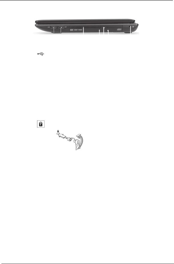
Right View
|
|
|
|
|
|
|
|
|
|
|
|
|
|
|
|
|
|
|
|
|
|
|
|
|
|
|
|
|
|
|
|
|
|
|
|
|
|
|
|
|
|
|
|
|
|
|
|
|
|
|
|
|
1 |
2 |
3 4 5 |
6 |
||||||||
|
|
|
|
|
|
|
|
|
|
|
|
|
No. |
Icon |
|
|
|
Item |
|
|
|
|
Description |
||
|
|
|
|
|
|
|
|
|
|
|
||
1 |
|
USB 2.0 ports |
Connect to USB 2.0 devices (e.g., USB mouse, |
|||||||||
|
|
|
|
|
|
|
USB camera). |
|
|
|||
2 |
|
Optical drive |
Internal optical drive; accepts CDs or DVDs. |
|||||||||
3 |
|
Optical drive |
Internal optical drive; accepts CDs or DVDs. |
|||||||||
|
|
access indicator |
|
|
|
|
|
|
||||
4 |
|
Optical drive eject |
Ejects the optical disc from the drive. |
|||||||||
|
|
button |
|
|
|
|
|
|
|
|
||
5 |
|
Emergency eject |
Ejects the optical drive tray when the computer |
|||||||||
|
|
hole |
|
|
is turned off. |
|
|
|||||
|
|
|
|
|
|
|
|
|
||||
|
|
|
|
|
|
|
Note: Insert a paper clip to the emergency eject |
|||||
|
|
|
|
|
|
|
hole to eject the optical drive tray when the |
|||||
|
|
|
|
|
|
|
computer is off. |
|
|
|||
6 |
|
Kensington lock |
Connects to a Kensington-compatible computer |
|||||||||
|
|
slot |
|
|
security lock. |
|
|
|||||
|
|
|
|
|
|
|
|
|
||||
|
|
|
|
|
|
|
Note: Wrap the computer security lock cable |
|||||
|
|
|
|
|
|
|
around an immovable object such as a table or |
|||||
|
|
|
|
|
|
|
handle of a locked drawer. Insert the lock into |
|||||
|
|
|
|
|
|
|
the notch and turn the key to secure the lock. |
|||||
|
|
|
|
|
|
|
Some keyless models are also available. |
|||||
12 |
Chapter 1 |
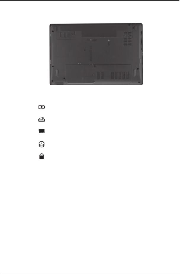
Base view
1 
2
 4
4
3
No. |
|
Icon |
Item |
Description |
|
|
|
|
|
|
|
1 |
|
|
|
Battery bay |
Houses the computer's battery pack. |
|
|
|
|
|
|
2 |
|
|
|
Battery release |
Releases the battery for removal. |
|
|
|
|||
|
|
|
|
latch |
|
|
|
|
|
|
|
|
|
|
|
|
|
3 |
|
|
|
Memory |
Houses the computer's main memory. |
|
|
|
|
compartment |
|
|
|
|
|
|
|
|
|
|
|
Hard disk bay - |
Houses the computer's hard disk (secured |
|
|
|
|
Main |
with screws). |
|
|
|
|
|
|
|
|
|
|
|
|
4 |
|
|
|
Battery lock |
Locks the battery in position. |
|
|
|
|
|
|
Chapter 1 |
13 |

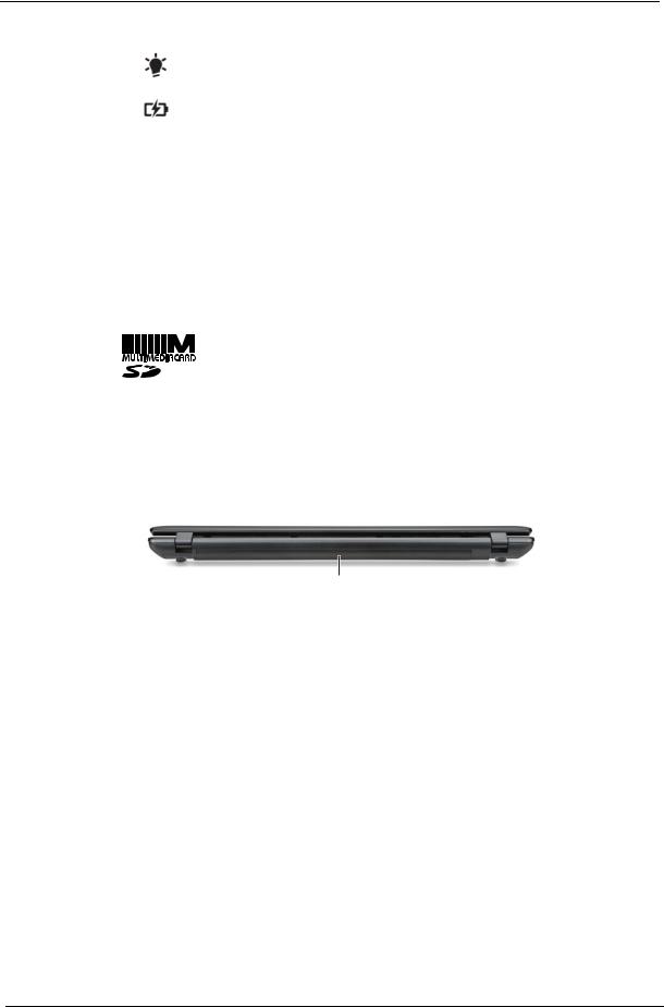
Indicators
The computer has several easy-to-read status indicators. The front panel indicators are visible even when the computer cover is closed.
Icon |
Function |
Description |
||
|
|
|
|
|
|
|
|
Power |
Indicates the computer's power status. |
|
|
|
|
|
|
|
|
Battery |
Indicates the computer's battery status. |
|
|
|
|
NOTE: 1. Charging: The light shows amber when |
|
|
|
|
|
|
|
|
|
the battery is charging. 2. Fully charged: The light |
|
|
|
|
|
|
|
|
|
shows green when in AC mode. |
|
|
|
|
|
|
|
|
HDD |
Indicates when the hard disk drive is active. |
|
|
|
|
|
|
|
|
Communication indicator |
Indicates the computer’s wireless connectivity |
|
|
|
|
device status. |
|
|
|
|
|
14 |
Chapter 1 |
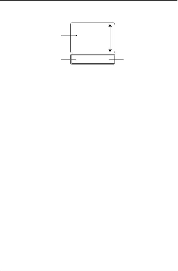
Touch Pad Basics
The following items show you how to use the TouchPad:
1
2 |
3 |
•Move your finger across the TouchPad (1) to move the cursor.
•Press the left (2) and right (3) buttons located beneath the TouchPad to perform selection and execution functions. These two buttons are similar to the left and right buttons on a mouse. Tapping on the TouchPad is the same as clicking the left button.
Function |
Left Button (2) |
Right Button (3) |
Main TouchPad (1) |
|
|
|
|
Execute |
Quickly click twice. |
|
Tap twice (at the same speed |
|
|
|
as double-clicking a mouse |
|
|
|
button). |
|
|
|
|
Select |
Click once. |
|
Tap once. |
|
|
|
|
Drag |
Click and hold, then use |
|
Tap twice (at the same speed |
|
finger on the TouchPad to |
|
as double-clicking a mouse |
|
drag the cursor. |
|
button); rest your finger on |
|
|
|
the TouchPad on the second |
|
|
|
tap and drag the cursor. |
|
|
|
|
Access |
|
Click once. |
|
context menu |
|
|
|
|
|
|
|
NOTE: When using the TouchPad, keep it - and your fingers - dry and clean. The TouchPad is sensitive to finger movement; hence, the lighter the touch, the better the response. Tapping too hard will not increase the TouchPad’s responsiveness.
Chapter 1 |
15 |
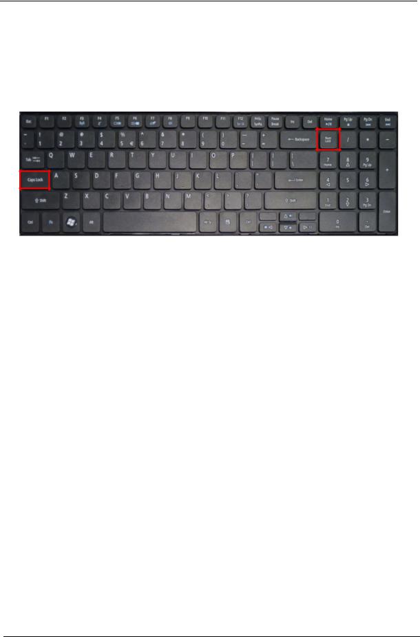
Using the Keyboard
The keyboard has full-sized keys and an embedded numeric keypad, separate cursor, lock, Windows, function and special keys.
Lock Keys and embedded numeric keypad
The keyboard has two lock keys which you can toggle on and off.
Lock key |
Description |
|
|
Caps Lock |
When Caps Lock is on, all alphabetic characters typed are in uppercase. |
Num Lock |
When Num Lock is on, the embedded keypad is in numeric mode. |
|
|
16 |
Chapter 1 |
Windows Keys
The keyboard has two keys that perform Windows-specific functions.
|
|
|
Key |
Description |
|
|
|
|
|
|
|
|
Windows key |
Pressed alone, this key has the same effect as clicking on the Windows Start button; |
|
|
|
|
it launches the Start menu. It can also be used with other keys to provide a variety of |
|
|
|
|
functions: |
|
|
|
|
< >: Open or close the Start menu |
|
|
|
|
< > + <D>: Display the desktop |
|
|
|
|
< > + <E>: Open Windows Explore |
|
|
|
|
< > + <F>: Search for a file or folder |
|
|
|
|
< > + <G>: Cycle through Sidebar gadgets |
|
|
|
|
< > + <L>: Lock your computer (if you are connected to a network domain), or |
|
|
|
|
switch users (if you're not connected to a network domain) |
|
|
|
|
< > + <M>: Minimizes all windows |
|
|
|
|
< > + <R>: Open the Run dialog box |
|
|
|
|
< > + <T>: Cycle through programs on the taskbar |
|
|
|
|
< > + <U>: Open Ease of Access Center |
|
|
|
|
< > + <X>: Open Windows Mobility Center |
|
|
|
|
< > + <BREAK>: Display the System Properties dialog box |
|
|
|
|
< > + <SHIFT+M>: Restore minimized windows to the desktop |
|
|
|
|
< > + <TAB>: Cycle through programs on the taskbar by using Windows Flip 3-D |
|
|
|
|
< > + <SPACEBAR>: Bring all gadgets to the front and select Windows Sidebar |
|
|
|
|
<CTRL> + < > + <F>: Search for computers (if you are on a network) |
|
|
|
|
<CTRL> + < > + <TAB>: Use the arrow keys to cycle through programs on the |
|
|
|
|
taskbar by using Windows Flip 3-D |
|
|
|
|
Note: Depending on your edition of Windows 7, some shortcuts may not function as |
|
|
|
|
described. |
|
|
|
Application |
This key has the same effect as clicking the right mouse button; it opens the |
|
|
|
||
|
|
|
key |
application's context menu. |
|
|
|
||
|
|
|
|
|
Chapter 1 |
17 |
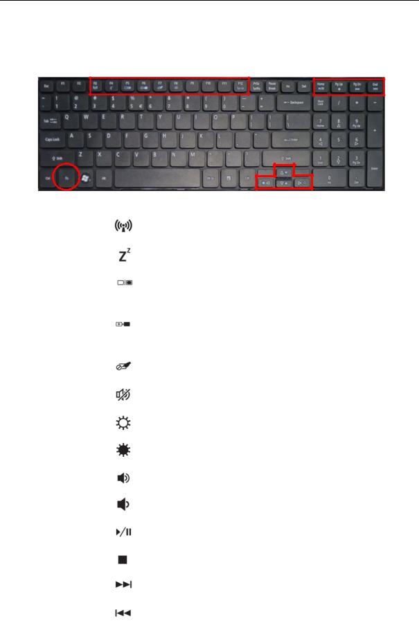
Hot Keys
The computer employs hotkeys or key combinations to access most of the computer’s controls like screen brightness, volume output and the BIOS utility.
To activate hot keys, press and hold the <Fn> key before pressing the other key in the hotkey combination.
|
Hotkey |
Icon |
Function |
Description |
|
|
|
|
|
|
|
|
<Fn> + <F3> |
|
Communication |
Enables/disables the computer’s |
|
|
|
|
|
communication devices. |
|
|
|
|
|
|
|
|
<Fn> + <F4> |
|
Sleep |
Puts the computer in Sleep mode. |
|
|
|
|
|
|
|
|
<Fn> + <F5> |
|
Display toggle |
Switches display output between the |
|
|
|
|
|
display screen, external monitor (if |
|
|
|
|
|
connected) and both. |
|
|
|
|
|
|
|
|
<Fn> + <F6> |
|
Screen blank |
Turns the display screen backlight off to |
|
|
|
|
|
save power. Press any key to |
|
|
|
|
|
return. |
|
|
|
|
|
|
|
|
<Fn> + <F7> |
|
Touchpad |
Turns the internal touchpad on and off. |
|
|
|
|
toggle |
|
|
|
|
|
|
|
|
|
<Fn> + <F8> |
|
Speaker toggle |
Turns the speakers on and off. |
|
|
|
|
|
|
|
|
<Fn> + <Z> |
|
Brightness up |
Increases the screen brightness. |
|
|
|
|
|
|
|
|
<Fn> + < Y> |
|
Brightness |
Decreases the screen brightness. |
|
|
|
|
down |
|
|
|
|
|
|
|
|
|
<Fn> + <U > |
|
Volume up |
Increases the sound volume. |
|
|
|
|
|
|
|
|
<Fn> + <V > |
|
Volume down |
Decreases the sound volume. |
|
|
|
|
|
|
|
|
<Fn> +<Home> |
|
Play/Pause |
Play or pause a selected media file. |
|
|
|
|
|
|
|
|
<Fn> +<Pg Up> |
|
Stop |
Stop playing the selected media file. |
|
|
|
|
|
|
|
|
<Fn> +<Pg Dn> |
|
Previous |
Return to the previous media file. |
|
|
|
|
|
|
|
|
<Fn> +<End> |
|
Next |
Jump to the next media file. |
|
|
|
|
|
|
|
|
|
|
|
|
|
18 |
Chapter 1 |

Hardware Specifications and Configurations
Processor
Item |
|
|
|
|
Specification |
|
|
|
|
||||
|
|
|
|
|
|
|
|
|
|
|
|
|
|
CPU type |
|
Intel® Core (i3,i5) Processor |
|
|
|
|
|
||||||
|
|
|
|
|
|
|
|
|
|
|
|
|
|
CPU package |
rPGA988A |
|
|
|
|
|
|
|
|
|
|||
|
|
|
|
|
|
|
|
|
|
|
|
|
|
Core Logic |
|
Two execution cores |
|
|
|
|
|
|
|
|
|||
|
|
• A 32-KB instruction and 32-KB data first-level cache (L1) for each core |
|
||||||||||
|
|
• A 256-KB shared instruction/data second-level cache (L2) for each core |
|
||||||||||
|
|
• Up to 4-MB shared instruction/data third-level cache (L3), shared among |
|
||||||||||
|
|
|
|
all cores |
|
|
|
|
|
|
|
|
|
|
|
|
|
|
|
|
|
|
|
|
|
|
|
Chipset |
|
• Mobile Intel® HM55 Express Chipset |
|
|
|
|
|
||||||
|
|
|
|
|
|
|
|
|
|
|
|
|
|
Processor Specifications |
|
|
|
|
|
|
|
|
|
||||
|
|
|
|
|
|
|
|
|
|
|
|
|
|
Item |
CPU |
|
|
Cores |
Bus |
Mfg Tech |
|
Cache |
Package |
Core |
|
||
Speed |
|
|
Speed |
|
Size |
|
Voltage |
|
|||||
|
|
|
|
|
|
|
|
|
|
||||
|
|
|
|
|
|
|
|
|
|
|
|
|
|
P6100 |
2 GHz |
|
2 Cores/ |
133 |
32 nm |
|
3 MB |
|
rPGA988A |
0.8-1.4V |
|
||
|
|
|
|
|
Mhz |
|
|
|
|
|
|
|
|
|
|
|
|
|
|
|
|
|
|
|
|
|
|
P6200 |
2.13 GHz |
|
2 Cores/ |
133 |
32 nm |
|
3 MB |
|
rPGA988A |
0.8-1.4V |
|
||
|
|
|
|
|
Mhz |
|
|
|
|
|
|
|
|
|
|
|
|
|
|
|
|
|
|
|
|
|
|
i3-350M |
2.26 GHz |
|
2 Cores/ |
350 |
32 nm |
|
3 MB |
|
rPGA988A |
0.8-1.4V |
|
||
|
|
|
4 threads |
MHz |
|
|
|
|
|
|
|
|
|
|
|
|
|
|
|
|
|
|
|
|
|
|
|
i3-370M |
2.4 GHz |
|
2 Cores/ |
370 |
32 nm |
|
3 MB |
|
rPGA988A |
0.8-1.4V |
|
||
|
|
|
4 threads |
MHz |
|
|
|
|
|
|
|
|
|
|
|
|
|
|
|
|
|
|
|
|
|
|
|
i3-380M |
2.53 GHz |
|
2 Cores/ |
380 |
32 nm |
|
3 MB |
|
rPGA988A |
0.8-1.4V |
|
||
|
|
|
4 threads |
MHz |
|
|
|
|
|
|
|
|
|
|
|
|
|
|
|
|
|
|
|
|
|
|
|
i5-460M |
2.53 GHz |
|
2 Cores/ |
460 |
32 nm |
|
3 MB |
|
rPGA988A |
0.8-1.4V |
|
||
|
up to 2.8 |
|
4 threads |
MHz |
|
|
|
|
|
|
|
|
|
|
GHz with |
|
|
|
|
|
|
|
|
|
|
|
|
|
turbo boost |
|
|
|
|
|
|
|
|
|
|
|
|
|
|
|
|
|
|
|
|
|
|
|
|
|
|
i5-560M |
2.66 GHz |
|
2 Cores/ |
560 |
32 nm |
|
3 MB |
|
rPGA988A |
0.8-1.4V |
|
||
|
up to 3.33 |
|
4 threads |
MHz |
|
|
|
|
|
|
|
|
|
|
GHz with |
|
|
|
|
|
|
|
|
|
|
|
|
|
turbo boost |
|
|
|
|
|
|
|
|
|
|
|
|
|
|
|
|
|
|
|
|
|
|
|
|
|
|
i5-580M |
2.66 Ghz |
|
2 Cores/ |
580 |
32 nm |
|
3 MB |
|
rPGA988A |
0.8-1.4V |
|
||
|
up to 3.33 |
|
4 threads |
MHz |
|
|
|
|
|
|
|
|
|
|
GHz with |
|
|
|
|
|
|
|
|
|
|
|
|
|
turbo boost |
|
|
|
|
|
|
|
|
|
|
|
|
|
|
|
|
|
|
|
|
|
|
|
|
|
|
CPU Fan True Value Table |
|
|
|
|
|
|
|
|
|
||||
|
|
|
|
|
|
|
|
|
|
|
|
|
|
CPU Temperature |
|
|
Fan Speed (RPM) |
|
|
|
SPL Spec (dBA) |
|
|
||||
|
|
|
|
|
|
|
|
|
|
|
|
|
|
60 |
|
|
|
2500 |
|
|
28 |
|
|
|
|
|
|
|
|
|
|
|
|
|
|
|
|
|
|
|
|
70 |
|
|
|
2900 |
|
|
31 |
|
|
|
|
|
|
|
|
|
|
|
|
|
|
|
|
|
|
|
|
80 |
|
|
|
3200 |
|
|
34 |
|
|
|
|
|
|
|
|
|
|
|
|
|
|
|
|
|
|
|
|
90 |
|
|
|
3600 |
|
|
37 |
|
|
|
|
|
|
|
|
|
|
|
|
|
|
|
|
|
|
|
|
100 |
|
|
|
4000 |
|
|
40 |
|
|
|
|
|
|
|
|
|
|
|
|
|
|
|
|
|
|
|
|
•Throttling 50%: On= 95°C; OFF=80°C
•OS shut down at 100°C; H/W shut down at 90°C
Chapter 1 |
19 |

CPU Fan True Value Table (UMA Tj=105)
CPU Temperature |
Fan Speed (RPM) |
SPL Spec (dBA) |
|
|
|
60 |
2300 |
28 |
70 |
2500 |
31 |
|
|
|
80 |
2700 |
34 |
|
|
|
90 |
3000 |
37 |
|
|
|
85 |
3300 |
40 |
|
|
|
•Throttling 50%: On= 85°C; OFF=72°C
•OS shut down at 104°C; H/W shut down at 92°C
CPU Fan True Value Table (DIS Tj=90)
CPU Temperature |
Fan Speed (RPM) |
SPL Spec (dBA) |
|
|
|
57 |
2500 |
28 |
|
|
|
64 |
2900 |
31 |
|
|
|
70 |
3200 |
34 |
|
|
|
78 |
3600 |
37 |
|
|
|
85 |
4000 |
40 |
|
|
|
•Throttling 50%: On= 85°C; OFF=72°C
•OS shut down at 104°C; H/W shut down at 92°C
CPU Fan True Value Table (UMA Tj=90)
CPU Temperature |
Fan Speed (RPM) |
SPL Spec (dBA) |
|
|
|
57 |
2300 |
28 |
|
|
|
64 |
2500 |
31 |
|
|
|
70 |
2700 |
34 |
|
|
|
78 |
3000 |
37 |
|
|
|
85 |
3300 |
40 |
|
|
|
•Throttling 50%: On= 85°C; OFF=72°C
•OS shut down at 104°C; H/W shut down at 92°C
System Memory
Item |
Specification |
|
|
Memory controller |
Built in at CPU |
Memory size |
512MB,1GB,2GB,4GB DDR3 RAM |
|
|
DIMM socket number |
2 |
|
|
Supports memory size per socket |
4 GB |
|
|
Supports maximum memory size |
8 GB |
|
|
Supports DIMM type |
Support DDR III 800/1066/1333Mhz |
|
SDRAM memory interface design |
|
|
Supports DIMM Speed |
800/1066Mhz SDRAM |
|
|
Support DIMM voltage |
+1.5V |
|
|
Supports DIMM package |
204pin DDRIII-SO-DIMM |
|
|
20 |
Chapter 1 |
Loading...