

Page 1

Aspire 5741/5741G Series
Service Guide
Service guide files and updates are available
on the ACER/CSD web; for more information,
please refer to http://csd.acer.com.tw
PRINTED IN TAIWAN
Page 2
Revision History
Please refer to the table below for the updates made on Aspire 5741/5741G service guides.
Date Chapter Updates
II
Page 3

Copyright
Copyright © 2010 by Acer Incorporated. All rights reserved. No part of this publication may be reproduced,
transmitted, transcribed, stored in a retrieval system, or translated into any language or computer language, in
any form or by any means, electronic, mechanical, magnetic, optical, chemical, manual or otherwise, without
the prior written permission of Acer Incorporated.
Disclaimer
The information in this guide is subject to change without notice.
Acer Incorporated makes no representations or warranties, either expressed or implied, with respect to the
contents hereof and specifically disclaims any warranties of merchantability or fitness for any particular
purpose. Any Acer Incorporated software described in this manual is sold or licensed "as is". Should the
programs prove defective following their purchase, the buyer (and not Acer Incorporated, its distributor, or its
dealer) assumes the entire cost of all necessary servicing, repair, and any incidental or consequential
damages resulting from any defect in the software.
Acer is a registered trademark of Acer Corporation.
Intel is a registered trademark of Intel Corporation.
Other brand and product names are trademarks and/or registered trademarks of their respective holders.
III
Page 4
Conventions
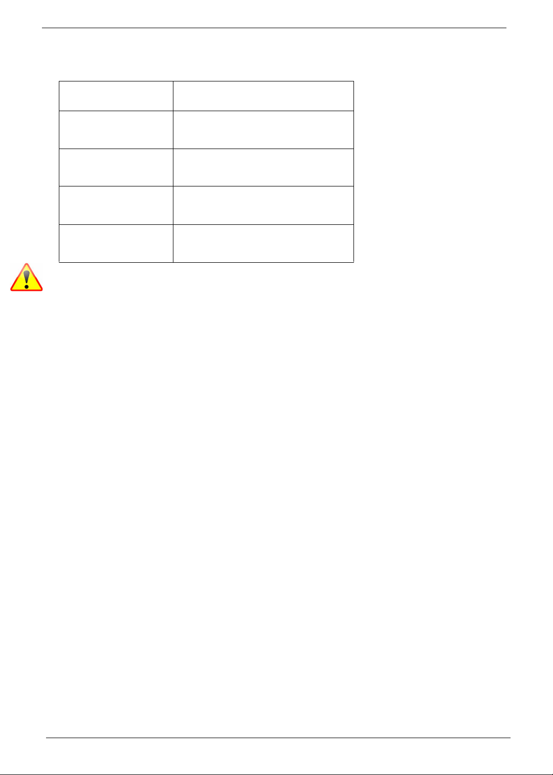
The following conventions are used in this manual:
SCREEN MESSAGES Denotes actual messages that appear
on screen.
NOTE Gives bits and pieces of additional
information related to the current
topic.
WARNING Alerts you to any damage that might
result from doing or not doing specific
actions.
CAUTION Gives precautionary measures to
avoid possible hardware or software
problems.
IMPORTANT Reminds you to do specific actions
relevant to the accomplishment of
procedures.
NOTE: This symbol where placed in the Service Guide designates a component that should be recycled
according to the local regulations.
IV
Page 5

Preface
Before using this information and the product it supports, please read the following general information.
1. This Service Guide provides you with all technical information relating to the BASIC CONFIGURATION
decided for Acer's "global" product offering. To better fit local market requirements and enhance product
competitiveness, your regional office MAY have decided to extend the functionality of a machine (e.g.
add-on card, modem, or extra memory capability). These LOCALIZED FEATURES will NOT be covered
in this generic service guide. In such cases, please contact your regional offices or the responsible
personnel/channel to provide you with further technical details.
2. Please note WHEN ORDERING FRU PARTS, that you should check the most up-to-date information
available on your regional web or channel. If, for whatever reason, a part number change is made, it will
not be noted in the printed Service Guide. For ACER-AUTHORIZED SERVICE PROVIDERS, your Acer
office may have a DIFFERENT part number code to those given in the FRU list of this printed Service
Guide. You MUST use the list provided by your regional Acer office to order FRU parts for repair and
service of customer machines.
V
Page 6

VI
Page 7

Table of Contents
System Specifications 1
Features . . . . . . . . . . . . . . . . . . . . . . . . . . . . . . . . . . . . . . . . . . . . . . . . . . . . . . . . . . . .1
System Block Diagram . . . . . . . . . . . . . . . . . . . . . . . . . . . . . . . . . . . . . . . . . . . . . . . . .5
Your Acer Notebook tour . . . . . . . . . . . . . . . . . . . . . . . . . . . . . . . . . . . . . . . . . . . . . . .6
Front View . . . . . . . . . . . . . . . . . . . . . . . . . . . . . . . . . . . . . . . . . . . . . . . . . . . . . . .6
Closed Front View . . . . . . . . . . . . . . . . . . . . . . . . . . . . . . . . . . . . . . . . . . . . . . . . .7
Left View . . . . . . . . . . . . . . . . . . . . . . . . . . . . . . . . . . . . . . . . . . . . . . . . . . . . . . . .7
Right View . . . . . . . . . . . . . . . . . . . . . . . . . . . . . . . . . . . . . . . . . . . . . . . . . . . . . . .8
Bottom View . . . . . . . . . . . . . . . . . . . . . . . . . . . . . . . . . . . . . . . . . . . . . . . . . . . . .9
Indicators . . . . . . . . . . . . . . . . . . . . . . . . . . . . . . . . . . . . . . . . . . . . . . . . . . . . . . .9
TouchPad Basics . . . . . . . . . . . . . . . . . . . . . . . . . . . . . . . . . . . . . . . . . . . . . . . .10
Using the Keyboard . . . . . . . . . . . . . . . . . . . . . . . . . . . . . . . . . . . . . . . . . . . . . . . . . .11
Lock Keys and embedded numeric keypad . . . . . . . . . . . . . . . . . . . . . . . . . . . .11
Windows Keys . . . . . . . . . . . . . . . . . . . . . . . . . . . . . . . . . . . . . . . . . . . . . . . . . .12
Hot Keys . . . . . . . . . . . . . . . . . . . . . . . . . . . . . . . . . . . . . . . . . . . . . . . . . . . . . . .13
Hardware Specifications and Configurations . . . . . . . . . . . . . . . . . . . . . . . . . . . . . . .14
System Utilities 21
BIOS Setup Utility . . . . . . . . . . . . . . . . . . . . . . . . . . . . . . . . . . . . . . . . . . . . . . . . . . . .21
Navigating the BIOS Utility . . . . . . . . . . . . . . . . . . . . . . . . . . . . . . . . . . . . . . . . .21
Aspire 5741/5741G BIOS . . . . . . . . . . . . . . . . . . . . . . . . . . . . . . . . . . . . . . . . . . . . . .22
Information . . . . . . . . . . . . . . . . . . . . . . . . . . . . . . . . . . . . . . . . . . . . . . . . . . . . .22
Main . . . . . . . . . . . . . . . . . . . . . . . . . . . . . . . . . . . . . . . . . . . . . . . . . . . . . . . . . .23
Security . . . . . . . . . . . . . . . . . . . . . . . . . . . . . . . . . . . . . . . . . . . . . . . . . . . . . . . .24
Boot . . . . . . . . . . . . . . . . . . . . . . . . . . . . . . . . . . . . . . . . . . . . . . . . . . . . . . . . . . .27
Exit . . . . . . . . . . . . . . . . . . . . . . . . . . . . . . . . . . . . . . . . . . . . . . . . . . . . . . . . . . .28
BIOS Flash Utilities . . . . . . . . . . . . . . . . . . . . . . . . . . . . . . . . . . . . . . . . . . . . . . . . . . .29
DOS Flash Utility . . . . . . . . . . . . . . . . . . . . . . . . . . . . . . . . . . . . . . . . . . . . . . . . .30
WinFlash Utility . . . . . . . . . . . . . . . . . . . . . . . . . . . . . . . . . . . . . . . . . . . . . . . . . .32
Remove HDD/BIOS Password Utilities . . . . . . . . . . . . . . . . . . . . . . . . . . . . . . . . . . . .33
Machine Disassembly and Replacement 39
Disassembly Requirements . . . . . . . . . . . . . . . . . . . . . . . . . . . . . . . . . . . . . . . . . . . .39
Pre-disassembly Instructions . . . . . . . . . . . . . . . . . . . . . . . . . . . . . . . . . . . . . . .40
Disassembly Process . . . . . . . . . . . . . . . . . . . . . . . . . . . . . . . . . . . . . . . . . . . . .41
External Module Disassembly Process . . . . . . . . . . . . . . . . . . . . . . . . . . . . . . . . . . .42
External Modules Disassembly Flowchart . . . . . . . . . . . . . . . . . . . . . . . . . . . . .42
Removing the Battery Pack . . . . . . . . . . . . . . . . . . . . . . . . . . . . . . . . . . . . . . . .43
Removing the SD Dummy Card . . . . . . . . . . . . . . . . . . . . . . . . . . . . . . . . . . . . .44
Removing the Optical Drive Module . . . . . . . . . . . . . . . . . . . . . . . . . . . . . . . . . .45
Removing the Logic Lower Door . . . . . . . . . . . . . . . . . . . . . . . . . . . . . . . . . . . . .47
Removing the 3G Cover . . . . . . . . . . . . . . . . . . . . . . . . . . . . . . . . . . . . . . . . . . .48
Removing the DIMM Module . . . . . . . . . . . . . . . . . . . . . . . . . . . . . . . . . . . . . . .49
Removing the WLAN Module . . . . . . . . . . . . . . . . . . . . . . . . . . . . . . . . . . . . . . .50
Removing the Hard Disk Drive Module . . . . . . . . . . . . . . . . . . . . . . . . . . . . . . . .52
Main Unit Disassembly Process . . . . . . . . . . . . . . . . . . . . . . . . . . . . . . . . . . . . . . . . .54
Main Unit Disassembly Flowchart . . . . . . . . . . . . . . . . . . . . . . . . . . . . . . . . . . . .54
Removing the Keyboard . . . . . . . . . . . . . . . . . . . . . . . . . . . . . . . . . . . . . . . . . . .55
Removing the Upper Cover . . . . . . . . . . . . . . . . . . . . . . . . . . . . . . . . . . . . . . . .57
Removing the Left Speaker Module . . . . . . . . . . . . . . . . . . . . . . . . . . . . . . . . . .61
Removing the Right Speaker Module . . . . . . . . . . . . . . . . . . . . . . . . . . . . . . . . .63
Removing the Power Board . . . . . . . . . . . . . . . . . . . . . . . . . . . . . . . . . . . . . . . .65
Removing the TouchPad Bracket . . . . . . . . . . . . . . . . . . . . . . . . . . . . . . . . . . . .66
Removing the Card Reader Board . . . . . . . . . . . . . . . . . . . . . . . . . . . . . . . . . . .68
VII
Page 8

Table of Contents
Removing the USB Board . . . . . . . . . . . . . . . . . . . . . . . . . . . . . . . . . . . . . . . . . .69
Removing the Bluetooth Board . . . . . . . . . . . . . . . . . . . . . . . . . . . . . . . . . . . . . .70
Removing the Mainboard . . . . . . . . . . . . . . . . . . . . . . . . . . . . . . . . . . . . . . . . . .71
Removing the Thermal Module . . . . . . . . . . . . . . . . . . . . . . . . . . . . . . . . . . . . . .75
Removing the CPU . . . . . . . . . . . . . . . . . . . . . . . . . . . . . . . . . . . . . . . . . . . . . . .77
LCD Module Disassembly Process . . . . . . . . . . . . . . . . . . . . . . . . . . . . . . . . . . . . . .78
LCD Module Disassembly Flowchart . . . . . . . . . . . . . . . . . . . . . . . . . . . . . . . . .78
Removing the LCD Assembly . . . . . . . . . . . . . . . . . . . . . . . . . . . . . . . . . . . . . . .79
Removing the LCD Bezel . . . . . . . . . . . . . . . . . . . . . . . . . . . . . . . . . . . . . . . . . .82
Removing the Camera Module . . . . . . . . . . . . . . . . . . . . . . . . . . . . . . . . . . . . . .83
Removing the LCD Panel . . . . . . . . . . . . . . . . . . . . . . . . . . . . . . . . . . . . . . . . . .84
Removing the LCD Brackets and FPC Cable . . . . . . . . . . . . . . . . . . . . . . . . . . .86
Removing the Microphone Cable . . . . . . . . . . . . . . . . . . . . . . . . . . . . . . . . . . . .89
Removing the Antennas . . . . . . . . . . . . . . . . . . . . . . . . . . . . . . . . . . . . . . . . . . .91
LCD Module Reassembly Procedure . . . . . . . . . . . . . . . . . . . . . . . . . . . . . . . . . . . . .93
Replacing the Antennas . . . . . . . . . . . . . . . . . . . . . . . . . . . . . . . . . . . . . . . . . . .93
Replacing the Microphone Cable . . . . . . . . . . . . . . . . . . . . . . . . . . . . . . . . . . . .95
Replacing the LCD Brackets and FPC Cable . . . . . . . . . . . . . . . . . . . . . . . . . . .96
Replacing the LCD Panel . . . . . . . . . . . . . . . . . . . . . . . . . . . . . . . . . . . . . . . . . .98
Replacing the Camera Module . . . . . . . . . . . . . . . . . . . . . . . . . . . . . . . . . . . . . .99
Replacing the LCD Bezel . . . . . . . . . . . . . . . . . . . . . . . . . . . . . . . . . . . . . . . . .100
Replacing the LCD Assembly . . . . . . . . . . . . . . . . . . . . . . . . . . . . . . . . . . . . . .101
Main Module Reassembly Procedure . . . . . . . . . . . . . . . . . . . . . . . . . . . . . . . . . . . .104
Replacing the CPU . . . . . . . . . . . . . . . . . . . . . . . . . . . . . . . . . . . . . . . . . . . . . .104
Replacing the Thermal Module . . . . . . . . . . . . . . . . . . . . . . . . . . . . . . . . . . . . .105
Replacing the Mainboard . . . . . . . . . . . . . . . . . . . . . . . . . . . . . . . . . . . . . . . . .106
Replacing the Bluetooth Board . . . . . . . . . . . . . . . . . . . . . . . . . . . . . . . . . . . . .109
Replacing the USB Board . . . . . . . . . . . . . . . . . . . . . . . . . . . . . . . . . . . . . . . . .110
Replacing the Card Reader Board . . . . . . . . . . . . . . . . . . . . . . . . . . . . . . . . . .111
Replacing the TouchPad Bracket . . . . . . . . . . . . . . . . . . . . . . . . . . . . . . . . . . .112
Replacing the Power Board . . . . . . . . . . . . . . . . . . . . . . . . . . . . . . . . . . . . . . .114
Replacing the Right Speaker Module . . . . . . . . . . . . . . . . . . . . . . . . . . . . . . . .115
Replacing the Left Speaker Module . . . . . . . . . . . . . . . . . . . . . . . . . . . . . . . . .116
Replacing the Upper Cover . . . . . . . . . . . . . . . . . . . . . . . . . . . . . . . . . . . . . . . .117
Replacing the Keyboard . . . . . . . . . . . . . . . . . . . . . . . . . . . . . . . . . . . . . . . . . .120
Replacing the Hard Disk Drive Module . . . . . . . . . . . . . . . . . . . . . . . . . . . . . . .121
Replacing the WLAN Module . . . . . . . . . . . . . . . . . . . . . . . . . . . . . . . . . . . . . .122
Replacing the DIMM Modules . . . . . . . . . . . . . . . . . . . . . . . . . . . . . . . . . . . . . .123
Replacing the 3G Cover . . . . . . . . . . . . . . . . . . . . . . . . . . . . . . . . . . . . . . . . . .124
Replacing the Logic Lower Door . . . . . . . . . . . . . . . . . . . . . . . . . . . . . . . . . . . .125
Replacing the ODD Module . . . . . . . . . . . . . . . . . . . . . . . . . . . . . . . . . . . . . . .126
Replacing the SD Dummy Card . . . . . . . . . . . . . . . . . . . . . . . . . . . . . . . . . . . .127
Replacing the Battery . . . . . . . . . . . . . . . . . . . . . . . . . . . . . . . . . . . . . . . . . . . .128
Troubleshooting 129
Common Problems . . . . . . . . . . . . . . . . . . . . . . . . . . . . . . . . . . . . . . . . . . . . . . . . . .129
Power On Issue . . . . . . . . . . . . . . . . . . . . . . . . . . . . . . . . . . . . . . . . . . . . . . . .130
No Display Issue . . . . . . . . . . . . . . . . . . . . . . . . . . . . . . . . . . . . . . . . . . . . . . . .131
Random Loss of BIOS Settings . . . . . . . . . . . . . . . . . . . . . . . . . . . . . . . . . . . .132
LCD Failure . . . . . . . . . . . . . . . . . . . . . . . . . . . . . . . . . . . . . . . . . . . . . . . . . . . .133
Built-In Keyboard Failure . . . . . . . . . . . . . . . . . . . . . . . . . . . . . . . . . . . . . . . . .133
TouchPad Failure . . . . . . . . . . . . . . . . . . . . . . . . . . . . . . . . . . . . . . . . . . . . . . .134
Internal Speaker Failure . . . . . . . . . . . . . . . . . . . . . . . . . . . . . . . . . . . . . . . . . .134
HDD Not Operating Correctly . . . . . . . . . . . . . . . . . . . . . . . . . . . . . . . . . . . . . .136
ODD Failure . . . . . . . . . . . . . . . . . . . . . . . . . . . . . . . . . . . . . . . . . . . . . . . . . . .137
VIII
Page 9

Table of Contents
Wireless Function Failure . . . . . . . . . . . . . . . . . . . . . . . . . . . . . . . . . . . . . . . . .140
Thermal Unit Failure . . . . . . . . . . . . . . . . . . . . . . . . . . . . . . . . . . . . . . . . . . . . .140
External Mouse Failure . . . . . . . . . . . . . . . . . . . . . . . . . . . . . . . . . . . . . . . . . . .141
Other Failures . . . . . . . . . . . . . . . . . . . . . . . . . . . . . . . . . . . . . . . . . . . . . . . . . .141
Intermittent Problems . . . . . . . . . . . . . . . . . . . . . . . . . . . . . . . . . . . . . . . . . . . . . . . .142
Undetermined Problems . . . . . . . . . . . . . . . . . . . . . . . . . . . . . . . . . . . . . . . . . . . . . .142
Post Codes . . . . . . . . . . . . . . . . . . . . . . . . . . . . . . . . . . . . . . . . . . . . . . . . . . . . . . . .143
Jumper and Connector Locations 149
Top View . . . . . . . . . . . . . . . . . . . . . . . . . . . . . . . . . . . . . . . . . . . . . . . . . . . . . .149
Bottom View . . . . . . . . . . . . . . . . . . . . . . . . . . . . . . . . . . . . . . . . . . . . . . . . . . .150
USB/B Board . . . . . . . . . . . . . . . . . . . . . . . . . . . . . . . . . . . . . . . . . . . . . . . . . . .151
Power Board . . . . . . . . . . . . . . . . . . . . . . . . . . . . . . . . . . . . . . . . . . . . . . . . . . .151
3G/B Board . . . . . . . . . . . . . . . . . . . . . . . . . . . . . . . . . . . . . . . . . . . . . . . . . . . .152
CR/B Board . . . . . . . . . . . . . . . . . . . . . . . . . . . . . . . . . . . . . . . . . . . . . . . . . . . .152
Clearing Password Check and BIOS Recovery . . . . . . . . . . . . . . . . . . . . . . . . . . . .153
Clearing Password Check . . . . . . . . . . . . . . . . . . . . . . . . . . . . . . . . . . . . . . . . .153
Clear CMOS Jumper . . . . . . . . . . . . . . . . . . . . . . . . . . . . . . . . . . . . . . . . . . . . .153
BIOS Recovery by Crisis Disk . . . . . . . . . . . . . . . . . . . . . . . . . . . . . . . . . . . . .154
FRU (Field Replaceable Unit) List 155
Aspire 5741/5741G Exploded Diagrams . . . . . . . . . . . . . . . . . . . . . . . . . . . . . . . . .156
Main Assembly . . . . . . . . . . . . . . . . . . . . . . . . . . . . . . . . . . . . . . . . . . . . . . . . .156
Upper Assembly . . . . . . . . . . . . . . . . . . . . . . . . . . . . . . . . . . . . . . . . . . . . . . . .157
LCD Assembly . . . . . . . . . . . . . . . . . . . . . . . . . . . . . . . . . . . . . . . . . . . . . . . . .158
Aspire 5741/5741G FRU List . . . . . . . . . . . . . . . . . . . . . . . . . . . . . . . . . . . . . . . . . .160
Screw List . . . . . . . . . . . . . . . . . . . . . . . . . . . . . . . . . . . . . . . . . . . . . . . . . . . . . . . . .168
Model Definition and Configuration 170
Aspire 5741 . . . . . . . . . . . . . . . . . . . . . . . . . . . . . . . . . . . . . . . . . . . . . . . . . . . . . . . .171
Aspire 5741G . . . . . . . . . . . . . . . . . . . . . . . . . . . . . . . . . . . . . . . . . . . . . . . . . . . . . .191
Test Compatible Components 229
Microsoft® Windows® 7 Environment Test . . . . . . . . . . . . . . . . . . . . . . . . . . . . . . .230
Online Support Information 243
Index 245
IX
Page 10

Table of Contents
X
Page 11

System Specifications
Features
Below is a brief summary of the computer’s many features:
NOTE: Items denoted with an (*) are only available for selected models.
Operating System
• Genuine Windows® 7 Home Premium 64-bit*
• Genuine Windows® 7 Home Basic 64-b i t*
Platform
• Intel® Core i3-330M/i3-350M processor (3 MB L3 cache, 2.13/2.26 GHz, 35 W), supporting Intel®
64 architecture, Intel® Smart Cache
• Mobile Intel® HM55 Express Chipset
Chapter 1
System Memory
• Dual-channel DDR3 SDRAM support:
• Up to 4 GB of DDR3 1066 MHz memory, upgradeable to 8 GB using two soDIMM modules
Display
• 15.6" HD 1366 x 768 pixel resolution, high-brightness (220-nit) Acer CineCrystal™ TFT LCD
• 16:9 aspect ratio
• 8 ms high-def response time
• 60% color gamut
Graphics
• Intel® HD Graphics with 128 MB of dedicated system memory, supporting Microsoft® DirectX® 10
(Aspire 5741)
• NVIDIA® GeForce® GT 320M with 1024 MB of dedicated DDR3 VRAM, supporting NVIDIA®
CUDA™, PhysX™, PureVideo® HD technology, OpenEXR High Dynamic-Range (HDR)
technology, Shader Model 4.0, Microsoft® DirectX® 10.1(Aspire 5741G)
• ATI Mobility Radeon™ HD 5470 with 512 MB of dedicated DDR3 VRAM, supporting Unified Video
Decoder (UVD), OpenEXR High Dynamic-Range (HDR) technology, Shader Model 5.0,
Microsoft® DirectX® 11, OpenGL ® 3.1, OpenCL™ 1.1(Aspire 5741G)
• Dual independent display support
• 16.7 million colors
• External resolution / refresh rates:
• VGA port up to 2048 x 1536: 85 Hz
• HDMI™ port up to 1920 x 1080: 60 Hz
Chapter 1 1
Page 12

• MPEG-2/DVD decoding
• WMV9 (VC-1) and H.264 (AVC) decoding
• Microsoft® DirectX® Video Acceleration (DXVA) application interface (API) (Aspire 5741G)
• HDMI™ (High-Definition Multimedia Interface) with HDCP (High-bandwidth Digital Content
Protection) support
Storage subsystem
• 2.5" hard disk drive
• DVD-Super Multi double-layer drive
• Multi-in-1 card reader
Audio
• Two built-in stereo speakers
• High-definition audio support
• MS-Sound compatible
• Built-in microphone
Storage
• 160/250/320/500/640 GB or larger hard disk drive
• Multi-in-1 card reader, supporting Secure Digital™ (SD) Card, MultiMed iaCard (MMC), Memory
Stick™ (MS), Memory Stick PRO™ (MS PRO), xD-Picture Card™ (xD)
Optical Media Drive
• 4X Blu-ray Disc™/DVD-Super Multi double-layer drive*:·
• Read: 24X CD-ROM, 24X CD-R, 24X CD-RW, 8X DVD-ROM, 8X DVD-R, 8X DVD+R, 8X
DVD-ROM DL, 6X DVD-R DL, 6X DVD+R DL, 8X DVD-RW, 8X DVD+RW, 5X DVD-RAM, 4X
BD-ROM, 4X BD-R, 2X BD-RE, 4X BD-ROM DL, 4X BD-R DL, 2X BD-RE DL
• Write: 24X CD-R, 16X CD-RW, 8X DVD-R, 8X DVD+R, 6X DVD-RW, 6X DVD+RW, 5X DVD-
RAM, 4X DVD+R DL, 4X DVD-R DL
• 8X DVD-Super Multi double-layer drive*:·
• Read: 24X CD-ROM, 24X CD-R, 24X CD-RW, 8X DVD-ROM, 8X DVD-R, 8X DVD+R, 6X
DVD-ROM DL, 6X DVD-R DL, 6X DVD+R DL, 6X DVD-RW, 6X DVD+RW, 5X DVD-RAM
• Write: 24X CD-R, 16X CD-RW, 8X DVD-R, 8X DVD+R, 4X DVD-R DL, 4X DVD+R DL, 6X
DVD-RW, 8X DVD+RW, 5X DVD-RAM
Communication
• Acer Video Conference, featuring:
• Acer Crystal Eye high-def webcam with 1280 x 1024 resolution
•WLAN:·
• Acer InviLink™ Nplify™ 802.1 1b/g/n Wi-Fi CERTIFIED™
• Acer InviLink™ 802.11b/g Wi-Fi CERTIFIED™
• Supporting Acer SignalUp™ wireless technology
• WP AN: Bluetooth® 2.1+EDR
• LAN: Gigabit Ethernet, Wake-on-LAN ready
2 Chapter 1
Page 13

Privacy control
• BIOS user, supervisor, HDD passwords
• Kensington lock slot
Dimensions and weight
• 381 (W) x 253 (D) x 25/34 (H) mm (15 x 9.9 x 0.98/1.3 inches)2.6 kg (5.74 lbs.)10 with 6-cell
battery pack
Power subsystem
• ACPI 3.0 CPU power management standard: supports Standby and Hibernation power-saving
modes
• 3-pin 65 W AC adapter (Aspire 5741):·
• 108 (W) x 46 (D) x 29.5 (H) mm (4.25 x 1.81 x 1.16 inches)
• 225 g (0.49 lbs.)10 with 180 cm DC cable
• 3-pin 90 W AC adapter (Aspire 5741G):
• 133 (W) x 59 (D) x 31 (H) mm (5.23 x 2.32 x 1.22 inches)
• 390 g (0.86 lbs.)10 with 180 cm DC cable
• Acer QuicCharge™ technology (Aspire 5741G):
• 80% charge in 1 hour·
• 2-hour rapid charge system-off
• 48.8 W 4400 mAh 6-cell Li-ion standard battery pack
• Estimated battery life: up to 4.0 hours (Aspire 5741)
• Estimated battery life: up to 3.0 hours (Aspire 5741G)
• ENERGY STAR®
Special keys and controls
• 103-/104-/107-key keyboard, with inverted "T" cursor layout, 1.8 mm (minimum) key travel
• Multi-gesture touchpad, supporting two-finger scroll, pinch, rotate, flip
• 1 1 function keys, four cursor keys, two Windows® keys, hotkey controls, independent standard
numeric keypad, international language support
• Media keys (printed on keyboard): play/pause, stop, previous, next
I/O interface
• Multi-in-1 card reader (SD™, MMC, MS, MS PRO, xD)
• Three USB 2.0 ports
• HDMI™ port with HDCP support
• External display (VGA) port
• Headphone/speaker/line-out jack
• Microphone-in jack
• Ethernet (RJ-45) port
• DC-in jack for AC adapter
Chapter 1 3
Page 14

Software
• Acer Crystal Eye
• Acer eRecovery Management
• Acer Backup Manager
• Adobe® Flash® Player
• Adobe® Reader®
• Cyberlink® Power DVD™
•eSobi™
• Google Toolbar™
• McAfee® Internet Security Suite 2009 Trial
• Microsoft® Works with Office Home and Student 2007 Trial
• MyWinLocker®
• Norton™ Online Backup
• NTI Media Maker™
• Oberon GameZone
• WildTangent®
Optional Items
• 1 GB / 2 GB / 4 GB DDR3 1066 MHz soDIMM module
• 6-cell Li-ion battery pack
• 3-pin 65 W AC adapter (Aspire 5741)
• 3-pin 90 W AC adapter (Aspire 5741G)
• External USB floppy disk drive
Warranty
• One-year International Travelers Warranty (ITW)
Environment
• Temperature:
• Operating: 5 °C to 35 °C
• Non-operating: -20 °C to 65 °C
• Humidity (non-condensing):
• Operating: 20% to 80%
• Non-operating: 20% to 80%
4 Chapter 1
Page 15
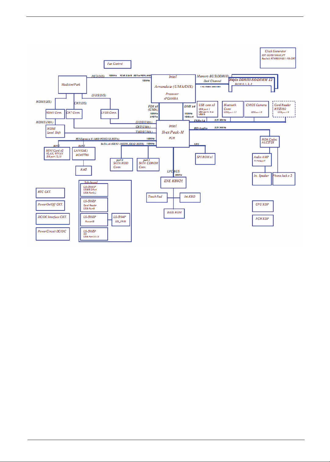
System Block Diagram
Chapter 1 5
Page 16
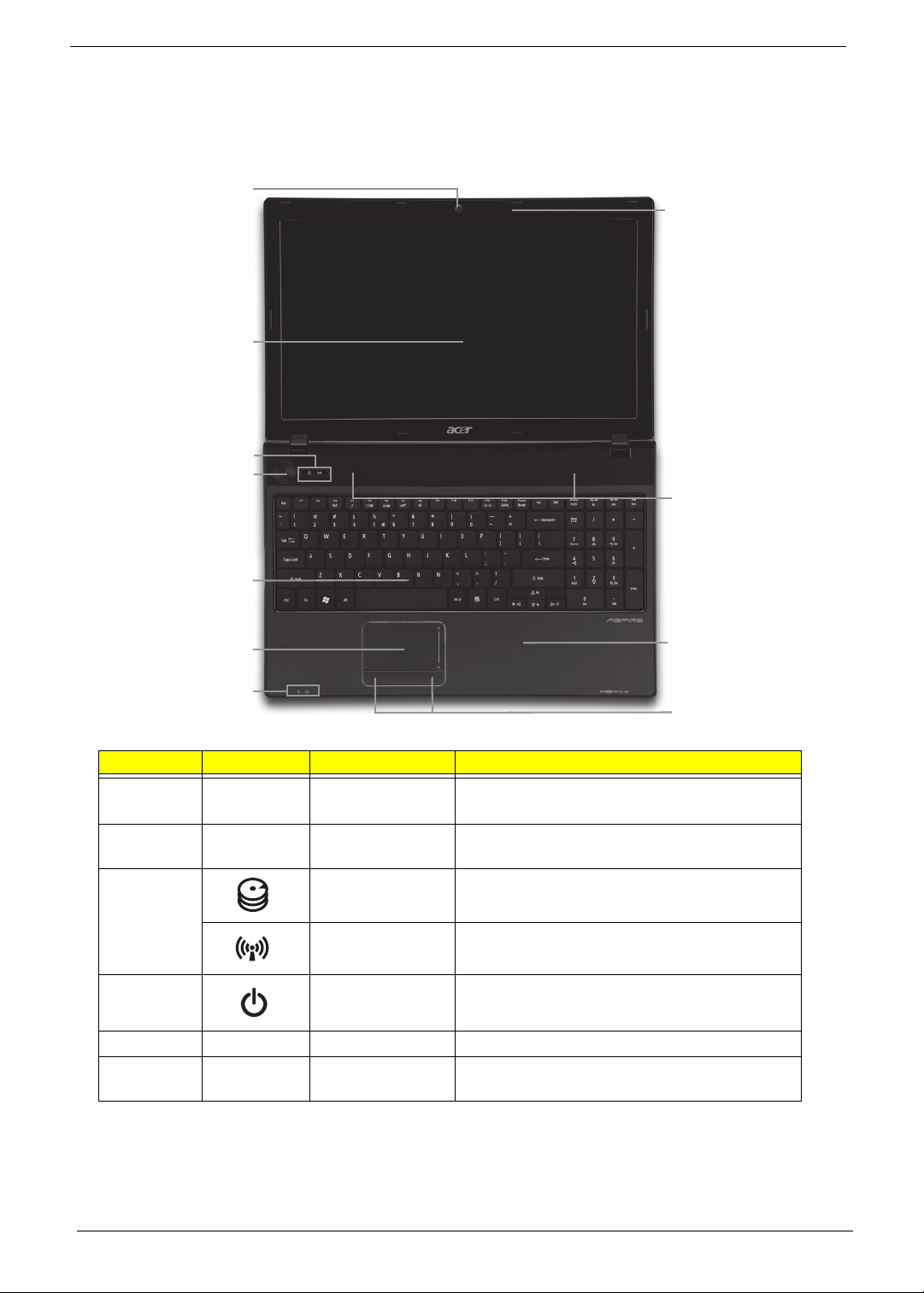
Your Acer Notebook tour
Front View
1
2
3
4
5
11
10
6
9
7
8
No. Icon Item Description
1 Acer Crystal Eye
webcam
2 Display screen Also called Liquid-Crystal Display (LCD),
3 HDD Indicates when the hard disk drive is active.
Communication
indicator
4 Power button Turns the computer on and off.
5 Keyboard For entering data into your computer.
6 T ouchPad T ouch-sensitive pointing device which functions
Web camera for video communication
(for selected models).
displays computer output.
Indicates the computer’s wireless connectivitoy
device status.
like a computer mouse.
6 Chapter 1
Page 17
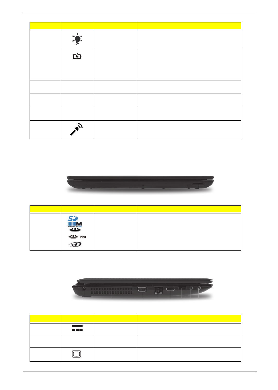
No. Icon Item Description
7
Power
1
Indicates the computer’s power status.
1
Battery
8 Click buttons (left
and right)
9 Palmrest Comfortable support area for your hands when
10 Speakers Left and right speakers deliver stereo audio
11 Microphone Internal microphone for recording sound.
NOTE: 1 The front panel indicators are visible even when the computer cover is closed.
Indicates the computer’s battery status.
1. Charging: The light shows amber when the
battery is charging.
2. Fully charged: The light shows blue when in
AC mode.
The left and right buttons function like the left
and right mouse buttons.
you use the computer.
output.
Closed Front View
1
No. Icon Item Description
1 Multi-in-1 card
reader
Accepts Secure Digital (SD), MultiMediaCard
(MMC), Memory Stick (MS), Memory Stick
PRO (MS PRO), xDPicture Card (xD).
NOTE: Push to remove/install the card.
Only one card can operate at any
given time.
Left View
1372 4 5 6
No. Icon Item Description
1 DC-in jack Connects to an AC adapter
2 Ventilation slots Enable the computer to stay cool, even after
prolonged use.
3 External display
(VGA) port
Connects to a display device
(e.g. external monitor, LCD projector).
Chapter 1 7
Page 18
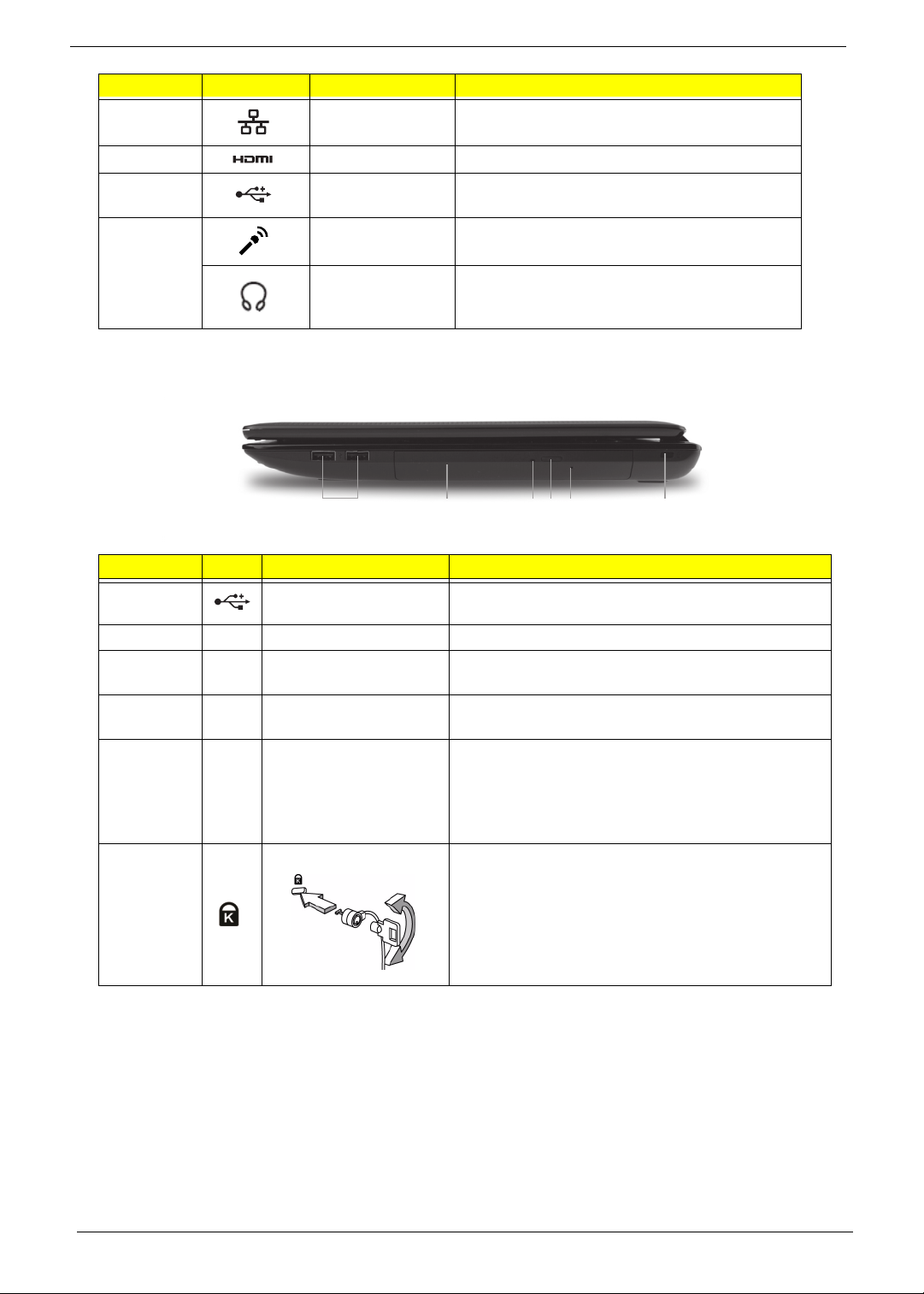
No. Icon Item Description
4 Ethernet (RJ-45)
port
5 HDMI Connect to HDMI devices
6 USB 2.0 ports Connect to USB 2.0 devices (e.g. USB mouse,
7 Microphone-in
jack
Connects to an Ethernet 10/100/1000-based
network.
USB camera).
Accepts input from external microphones.
Headphones/
speaker/line-out
jack
Connects to audio line-out devices
(e.g. speakers, headphones).
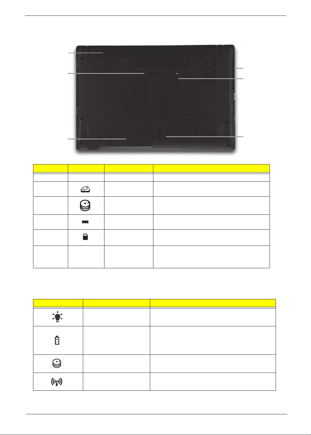
Right View
123456
No. Icon Item Description
1 USB 2.0 ports Connect to USB 2.0 devices (e.g. USB mouse, USB
camera).
2 Optical drive Internal optical drive; accepts CDs or DVDs.
3 Optical disk access
indicator
4 Optical drive eject
button
5 Emergency eject hole Ej ects the optical drive tray when the computer is
6 Kensington lock slot Connects to a Kensington-compatible computer
Lights up when the optical drive is active.
Ejects the optical disk from the drive.
turned off.
Note: Insert a paper clip into the emergency eject
hole to eject the optical drive tray when the computer
is off.
security lock.
Note: Wrap the computer security lock cable around
an immovable object such as a table or handle of a
locked drawer. Insert the lock into the notch and turn
the key to secure the lock. Some keyless models are
also available.
8 Chapter 1
Page 19
Bottom View
1
2
6
5
3
No. Icon Item Description
1 Battery bay Houses the computer's battery pack.
2 Battery release
latch
3 Hard disk bay Houses the computer's hard disk (secured
4 Memory
compartment
5 Battery lock Locks the battery in position.
6 Ventilation slots
and cooling fan
Releases the battery for removal.
with screws).
Houses the computer's main memory.
Enable the computer to stay cool, even after
prolonged use.
Note: Do not cover or obstruct the fan opening.
Indicators
The computer has several easy-to-read status indicators.
Icon Function Description
Power Indicates the computer's power status.
4
Battery Indicates the computer's battery status.
NOTE: 1. Charging: The light shows amber when
the battery is charging. 2. Fully charged: The light
shows green when in AC mode.
HDD Indicates when the hard disk drive is active.
Communication indicator Indicates the computer’s wireless connectivitoy
device status.
Chapter 1 9
Page 20
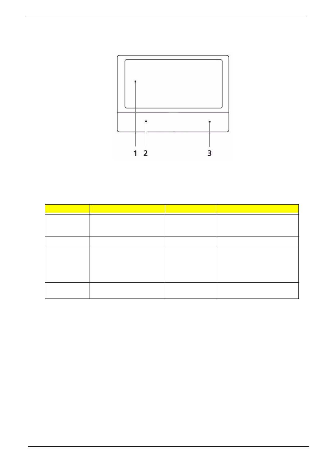
TouchPad Basics
The following items show you how to use the TouchPad:
• Move your finger across the TouchPad (1) to move the cursor.
• Press the left (2) and right (3) buttons located beneath the TouchPad to perform selection and
execution functions. These two buttons are similar to the left and right buttons on a mouse.
Tapping on the TouchPad is the same as clicking the left button.
Function Left Button (2) Right Button (3) Main TouchPad (1)
Execute Quickly click twice. Tap twice (at the same speed
Select Click once. Tap once.
Drag Click and hold, then use
finger on the TouchPad to
drag the cursor.
Access
context menu
as double-clicking a mouse
button).
Tap twice (at the same speed
as double-clicking a mouse
button); rest your finger on
the TouchPad on the second
tap and drag the cursor.
Click once.
NOTE: When using the T ouchPad, keep it - and your fingers - dry and clean. The TouchPad is sensitive to
finger movement; hence, the lighter the touch, the better the response. Tapping too hard will not
increase the TouchPad’s responsiveness.
10 Chapter 1
Page 21
Using the Keyboard
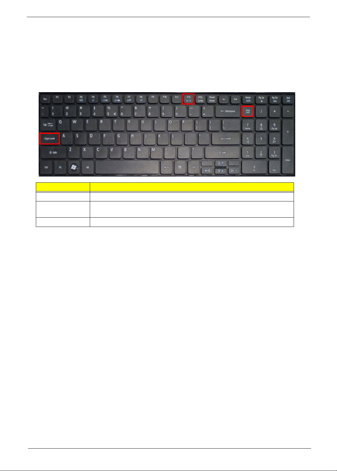
The keyboard has full-sized keys and an embedded numeric keypad, separate cursor, lock, Windows, function
and special keys.
Lock Keys and embedded numeric keypad
The keyboard has two lock keys which you can toggle on and off.
Lock key Description
Caps Lock When Caps Lock is on, all alphabetic chara c ters typed are in uppercase.
Scroll Lock When Scroll Lock is on, the contents of a text window scroll without moving the
cursor.
Num Lock When Num Lock is on, the embedded keypad is in numeric mode.
Chapter 1 11
Page 22
Windows Keys
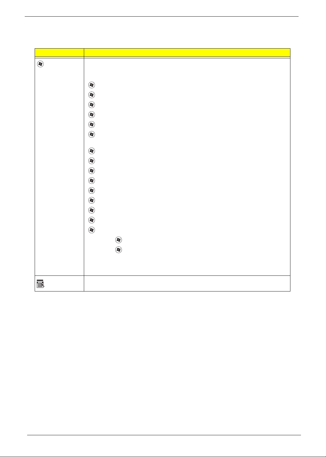
The keyboard has two keys that perform Windows-specific functions.
Key Description
Windows key Pressed alone, this key has the same effect as clicking on the Windows Start button;
it launches the Start menu. It can also be used with other keys to provide a variety of
functions:
<>: Open or close the S tart menu
<> + <D>: Display the desktop
<> + <E>: Open Windows Explore
<> + <F>: Search for a file or folder
<> + <G>: Cycle through Sidebar gadgets
<> + <L>: Lock your computer (if you are connected to a network domain), or
switch users (if you're not connected to a network domain)
<> + <M>: Minimizes all windows
<> + <R>: Open the Run dialog box
<> + <T>: Cycle through programs on the taskbar
<> + <U>: Open Ease of Access Center
<> + <X>: Open Windows Mobility Center
<> + <BREAK>: Display the System Properties dialog box
<> + <SHIFT+M>: Restore minimized windows to the desktop
<> + <TAB>: Cycle through programs on the taskbar by using Windows Flip 3-D
<> + <SPACEBAR>: Bring all gadgets to the front and select Windows Sidebar
Application
key
<CTRL> +
<CTRL> + <> + <TAB>: Use the arrow keys to cycle through programs on the
Note: Depending on your edition of Windows 7, some shortcuts may not function as
This key has the same effect as clicking the right mouse button; it opens the
application's context menu.
<> + <F>: Search for computers (if you are on a network)
taskbar by using Windows Flip 3-D
described.
12 Chapter 1
Page 23
Hot Keys
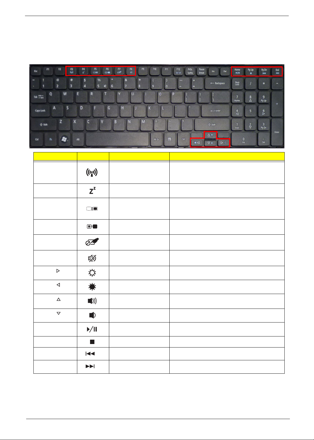
The computer employs hotkeys or key combinations to access most of the computer’s controls like screen
brightness, volume output and the BIOS utility.
To activate hot keys, press and hold the <Fn> key before pressing the other key in the hotkey combination.
Hotkey Icon Function Description
<Fn> + <F3> Communication key Enables / disables the computer's
communication devices. (Communication
devices may vary by configuration.)
<Fn> + <F4> Sleep Puts the computer in Sleep mode.
<Fn> + <F5> Display toggle Switches display output between the display
screen, external monitor (if connected) and
both.
<Fn> + <F6> Display Off Turns the display screen backlight off to save
power. Press any key to return.
<Fn> + <F7> Touchpad toggle Turns the internal touchpad on and off.
<Fn> + <F8> Speaker toggle Turns the speakers on and off.
<Fn> + < > Brightness up Increases the screen brightness.
<Fn> + < > Brightness down Decreases the screen brightness.
<Fn> + < >
<Fn> + < >
<Fn> + <Home> Play/Pause Play or pause a selected media file.
<Fn> + <Pg Up> Stop Stop playing the selected media file.
<Fn> + <Pg Dn> Previous Return to the previous media file.
<Fn> + <End> Next Jump to the next media file.
Volume up Increases the sound volume.
Volume down Decreases the sound volume.
Chapter 1 13
Page 24
Hardware Specifications and Configurations
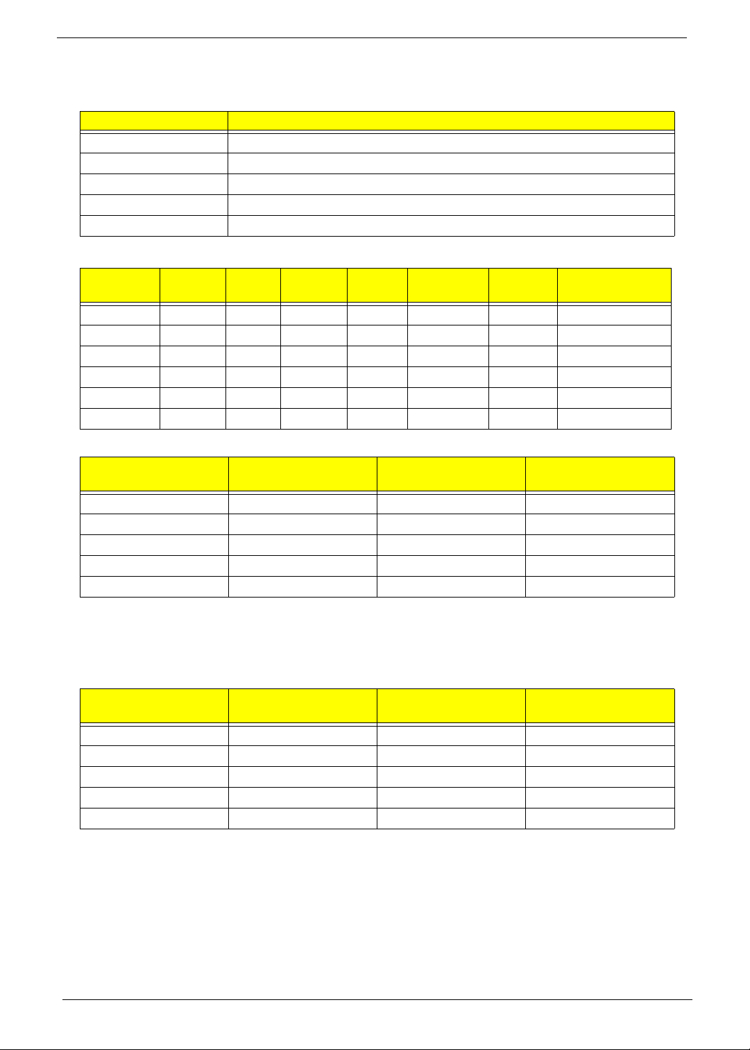
Item Specification
CPU Intel Mobile Calpella
Graphics Integrated VGA for Arrandale
CPU Package rPGA988A
Power 4M (Arrandale) L3 shared among all cores
On-die Cache 32KB L1 & 256K L2 for each core
Processor Specifications
Item
Ci3330M 2.13 2 330 M 3 MB PGA988 35W KC.33001.DMP
Ci3350M 2.26 2 350 M 3 MB PGA988 35W KC.35001.DMP
Ci5430M 2.26 2 430 M 3 MB PGA988 35W KC.43001.DMP
Ci5520M 2.24 2 520 M 3 MB PGA988P 35W KC.52001.DMP
Ci5540M 2.53 2 540 M 3 MB PGA988 35W KC.54001.DMP
Ci7620M 2.66 2 620 M 4 MB PGA988P 35W KC.62001.DMP
CPU Fan True Value Table (Tj = 90)
CPU Temp (°C)
Core 0
45 57 2300 28
52 64 3000 31
59 70 3100 34
65 78 3500 37
72 85 3900 40
• Throttling 50%: On=85°C, Off=72°C
• OS Shutdown: 104°C
• H/W Shutdown: 92°C
CPU Fan True Value Table (Tj = 105)
CPU Temp (°C)
Core 0
45 60 2300 28
55 70 3000 31
65 80 3100 34
75 90 3500 37
85 100 3900 40
CPU
Speed
Core
s
Speed
CPU Temp (°C)
Core 1
CPU Temp (°C)
Core 1
Bus
Cache
Size
Package
Fan Speed (rpm) SPL Spec (dBA)
Fan Speed (rpm) SPL Spec (dBA)
Core
Voltage
Acer P/N
• Throttling 50%: On=100°C, Off=85°C
• OS Shutdown: 104°C
• H/W Shutdown: 92°C
14 Chapter 1
Page 25
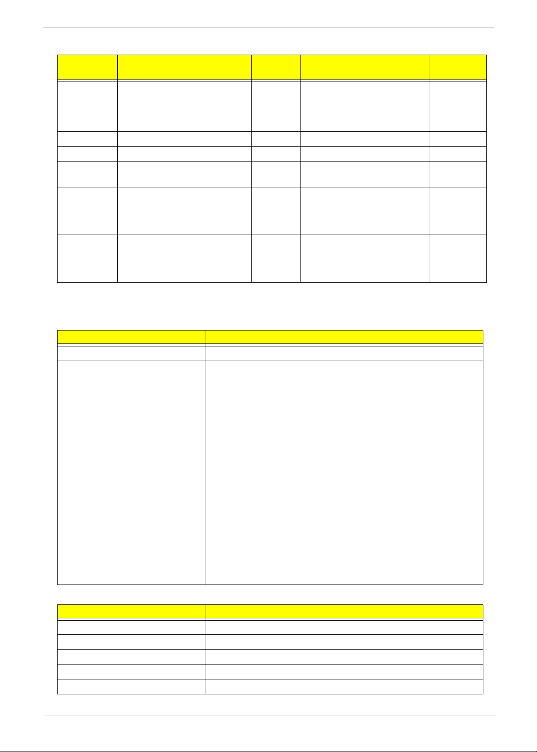
Fan Acoustic Specifications
Operation
Mode
Fan off Windows Idle (HDD random
seek)
Fan 1 Windows Idle 28 N/A 7
Fan 2 Windows Idle, HDD spinning 31 N/A 7
Fan 3 Play Movie (read from HDD),
Play TV (TV tuner sku)
Fan 4 3DMark06,Pri me95,
Prime95+Play TV(TV tuner
sku), acer screen saver, HDD
spinning
Fan 5 TAT100% or
Thermanow100%,3DMark06,
at ambient 35C, HDD
spinning
NOTE: Tone:20~399Hz refer to slope of Ecma-074, 400~20K Hz < 7 Prominence ratio,No pattern occurred on
Prominence vs. time diagram
BIOS
Item Specification
BIOS vendor Insyde BIOS
BIOS ROM type Flash
Features • Flash ROM 4MB
Application
• Support ISIPP
• Support Acer UI
• Support multi-boot
• Suspend to RAM (S3)/Disk (S4)
• V arious hot-key s for system control
• Support SMBIOS 2.3, PCI2.2.
• Refer to Acer BIOS specification.
• DMI utility for BIOS serial number configurable/asset tag
• Support PXE
• Support Y2K solution
• Support WinFlash
• Wake on LAN from S3
• Wake on LAN form S4 in AC mode
• System information
SPL
dBA
N/A • 20~3.99kHz less than or
34 N/A 7
37 N/A 7
40 N/A 7
Loudness (Sone) Tone (dB)
equal to: 0.5
• 4K~20kHz less than or
equal to: 0.035
7
System Memory
Item Specification
Memory size 8GB maximum
DIMM socket number 2
Supports memory size per socket 4GB
Supports DIMM type 204-pin +1.5V DDRIII
Supports DIMM Speed 800/1066 MHz
Chapter 1 15
Page 26
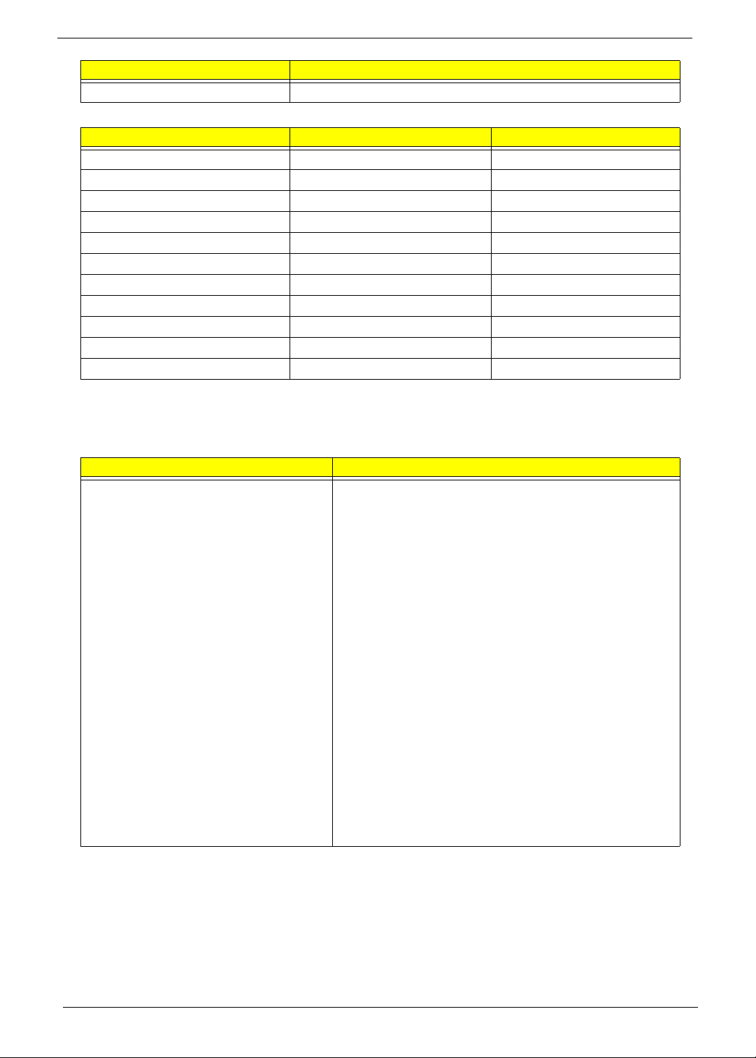
Item Specification
Supports DIMM voltage 1.5V
Memory Combinations
Slot 1 Slot 2 Total Memory
0MB 1024MB 1024MB
0MB 2048MB 2048MB
0MB 4096MB 4096MB
1024MB 0MB 1024MB
1024MB 1024MB 2048MB
1024MB 2048MB 3072MB
2048MB 0MB 2048MB
2048MB 1024MB 3072MB
2048MB 2048MB 4096MB
2048MB 4096MB 6144MB
4096MB 4096MB 8192MB
NOTE: Above table lists some system memory configurations. You may combine DIMMs with various
capacities to form other combinations. In the above table, the configuration of slot 1 and slot 2 could be
reversed.
Onboard LAN
Item Specification
Manufacturer Broadcom 57780KMLG for GIGA LAN
• Integrated 10/100/10000BASE-T transceiver
• Automatic MDI crossover function
• PCIe V1.1 compliant
• 10/100/10000BASE-T full -duplex/half -duplex MAC
• Receive side scaling(RSS) for multicore processors
• Complies with IEEE 802.3, 802.3u, 802.3ab, and
802.1p
• Wake on LAN (WOL) support meeting the ACPI
requirements
• Statistics for SNMP MIB II, Ethernet-like MIB, and
Ethernet MIB (IEEE 802.3z, Clause 30)
• Self-boot feature, utilizing smaller EEPROM size with
ability to use on-chip memory
• Supports iSCSI boott
• PCI Express CLKREQ support
• Integrated switching regulator for improved power
consumption
• IPv4 and IPv6 large send offload and checksum
offload(LSO/TCO)
16 Chapter 1
Page 27
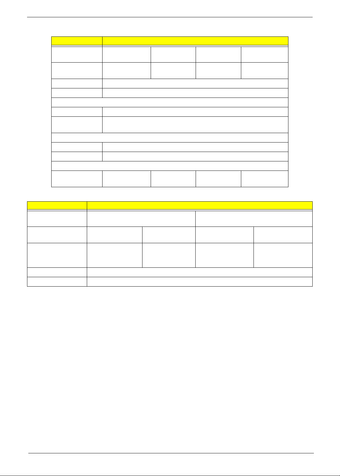
Hard Disk Drive Interface
Item Specification
Vendor & Model
Name
Capacity (MB) 160, 250, 320,
Bytes per sector 512
Data heads 2-4
Drive Format
Disks 1-2
Spindle speed
(RPM)
Performance Specifications
Buffer size 8 MB
Interface SATA
DC Power Requirements
Voltage
tolerance
Super-Multi Drive Module
Item Specification
Vendor & model
HLDS GT20N Sony AD7580S
name
Performance
With CD Diskette With DVD Diskette With CD Diskette With DVD Diskette
Specification
Transfer rate (MB/
sec)
Sustained:
3,600 KB/s (24x)
max.
Buffer Memory 2 MB
Interface SATA
Seagate HGST Toshiba Western Digital
500
160, 250,
320, 500
160, 250,
320, 500
160, 250, 320,
500, 640
5400
5V ±5% 5V ±5% 5V ±5% 5V ±5%
Sustained:
1 1 .08 Mbytes/s
Sustained:
1,571 (typical)
Sustained:
10,993 (typical)
(8x) max.
Chapter 1 17
Page 28
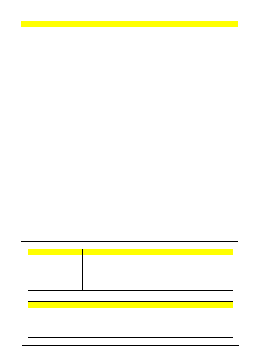
Item Specification
Applicable disc
formats
DVD-ROM:
4.7GB (Single Layer)
8.5GB (Dual Layer)
DVD-R:
3.95GB (Ver. 1.0: read only)
4.7GB (Ver. 2.0 for Authoring: read only)
4.7GB (Ver. 2.1 for General: read & write)
(DL) 8.5GB (Ver. 3.0)
DVD-RW:
4.7GB (Ver. 1.2/ Rev 1.0, 2.0, 3.0)
DVD-RAM: 1.46GB/side, 4.7GB/side
(Ver. 2.2)
DVD+R: 4.7GB (Ver. 1. 3)
(DL) 8.5GB (Ver. 1.1)
DVD+RW:
4.7GB (Vol.1 Ver.1.3)
DVD Read:
DVD-ROM (DVD-5, DVD-9, DVD-10, DVD-
18), DVD-Video, DVD-Audio, SACD (Hybrid),
UDF DVD, DVD-R, DVD-R DL, DVD-R 3.95
GB, DVD-R Authoring, DVD-R Multi-Border,
DVD-RW, DVD+R, DVD+R DL, DVD+R
Multi-Session, DVD+RW, DVD-RAM V1.0,
DVDRAM
V2.0 & 2.1 &2.2.
CD Read:
CD-DA, CD-ROM Mode-1, CD-ROM/XA
Mode-2 Form-1 and Mode-2 Form-2, CD-i,
CD-i
Bridge, Video-CD (MPEG-1), Karaoke CD,
Photo-CD, Enhanced CD, CD Plus, CD
Extra, itrax
CD, CD-Text, UDF CD, CD-R, and CD-RW
CD-ROM Mode-1 data disc
CD-ROM Mode-2 data disc
CD-ROM XA, CD-I, Photo-CD Multi-
DVD Write:
DVD Data & Video
Session, Video CD
CD-Audio Disc
Mixed mode CD-ROM disc (data and
audio)
CD-Extra
CD-Text
CD Read:
CD-DA, CD-ROM Mode-1, CD-ROM/XA
Mode-2 Form-1 and Mode-2 Form-2, CD-i,
Video-
CD, CD-Text
CD-R (Conforming to “Orange Book Part
2”: read & write)
CD-RW (Conforming to “Orange Book
Part 3”: read & write)
Loading mechanism Drawer (Solenoid Open)
Tact SW (Open)
Emergency Release (draw open hole)
Power Requirement
Input Voltage DC 5 V +/- 5%
Audio Interface
Item Specification
Chipset Realtek ALC272-X
Features • High Definition Audio Codec
• Single Analogue MIC
• 2.0 Watt speaker/5cc chamber/speaker size 18 phi, x2
• Headphone-out w/o SPDIF-out
Power and Keyboard Controller
Item Specification
Controller ENE KB926
Total number of keypads 99-/100-/103-key keyboard
Windows logo key Yes
Hotkeys See “Hot Keys” on page 13.
18 Chapter 1
Page 29

Battery
Item
Vendor & model name SANYO/SONY/PANASONIC/SAMSUNG/SIMPLO AS2009A
Battery Type Li-ion
Pack capacity 4400 mAh
Normal Voltage 2.2 Ah
Package configuration 3S2P
Specification
6 Cell
Chapter 1 19
Page 30
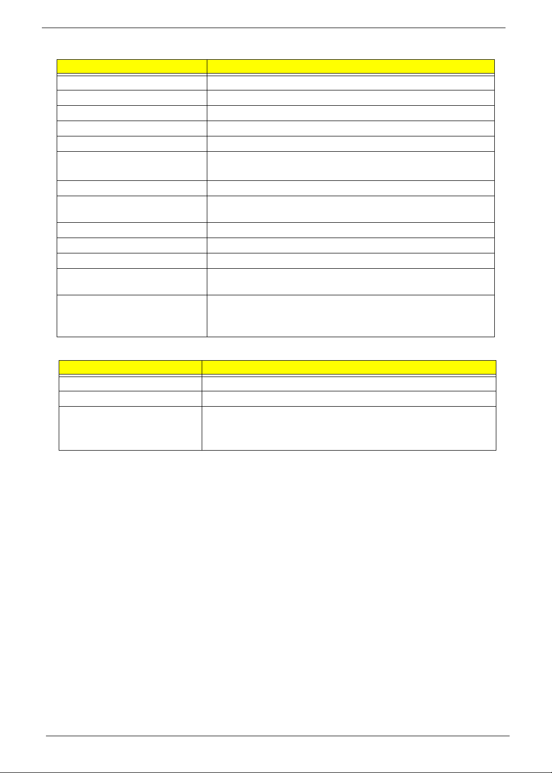
LCD 15.6”
Item Specification
Vendor/model name AUO/CPT/CMO/Samsung/LCD/INL
Screen Diagonal (mm) 15.6 inches
Display resolution (pixels) 1366 x 768 WXGA Clare
Pixel Pitch 0.204 x 0.204
Display Mode Normal
2
220
Typical White Luminance (cd/m
)
(also called Brightness)
Contrast Ratio 500 typical
Response Time (Optical Rise
8
Time/Fall Time) msec
Luminance Uniformity 1.25 max
Electrical Interface LVDS
Support Color 262K
Viewing Angle (up/down/right/
15/35/45/45
left)
Temperature Range (°C)
Operating
0 to +50
-20 to +60
Storage (shipping)
Card Reader
Item Specification
Part Name RealTek RT5160
Package 5-in-1 card reader
General Features • PCI-E interface
• Push-push type
•Dummy card
20 Chapter 1
Page 31

Chapter 2
System Utilities
BIOS Setup Utility
The BIOS Setup Utility is a hardware configuration program built into your computer’s BIOS (Basic Input/
Output System).
Y our computer is already properly configured and optimized, and you do not need to run this utility . However, if
you encounter configuration problems, you may need to run Setup. Please also refer to Chapter 4
Troubleshooting when problem arises.
To activate the BIOS Utility, press F2 during POST (when “Press <F2> to enter Setup” message is prompted
on the bottom of screen).
The default parameter of F12 Boot Menu is set to “disabled”. If you want to change boot device without
entering BIOS Setup Utility, please set the parameter to “enabled”.
Press <F12> during POST to enter multi-boot menu. In this menu, user can change boot device without
entering BIOS SETUP Utility.
Navigating the BIOS Utility
There are six menu options: Information, Main, Security, Boot, and Exit.
Follow these instructions:
• To choose a menu, use the left and right arrow keys.
• To choose an item, use the up and down arrow keys.
• To change the value of a parameter, press F5 or F6.
• Press Esc while you are in any of the menu options to go to the Exit menu.
• In any menu, you can load default settings by pressing F9. You can also press F10 to save any
changes made and exit the BIOS Setup Utility.
NOTE: You can change the value of a parameter if it is enclosed in square brackets. Navigation keys for a
particular menu are shown on the bottom of the screen. Help for parameters are found in the Item
Specific Help part of the screen. Read this carefully when making changes to parameter values. Please
note that system information is subject to different models.
Chapter 2 21
Page 32
Aspire 5741/5741G BIOS
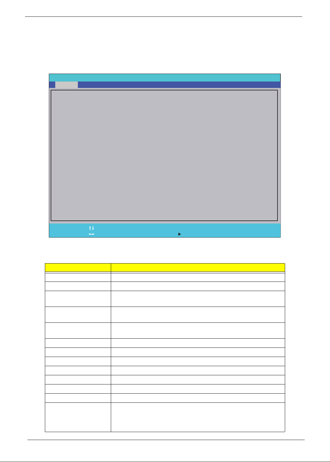
Information
The Information screen displays a summary of the computer hardware information.
InsydeH20 Setup Utility Rev. 3.5
Main Boot
SecurityInformation
Intel(R) Core(TM) i3 CPU M 330 @ 2.13GHz
CPU Type
CPU Type
CPU Speed
CPU Speed
HDD Model Name:
HDD Model Name:
HDD Serial Number:
HDD Serial Number:
ATAPI Model Name:
ATAPI Model Name:
System BIOS Version:
System BIOS Version:
KBC BIOS Version:
KBC BIOS Version:
VGA BIOS Version:
VGA BIOS Version:
Serial Number:
Serial Number:
Asset Tag Number:
Asset Tag Number:
Product Name:
Product Name:
Manufacturer Name:
Manufacturer Name:
UUID:
UUID:
Intel(R) Core(TM) i3 CPU M 330 @ 2.13GHz
2.13GHz
2.13GHz
WDC WD3200BEVT-22A23T0
WDC WD3200BEVT-22A23T0
WD-WXB0AA9N9724
WD-WXB0AA9N9724
HL-DT-STDVDRAM GT30N
HL-DT-STDVDRAM GT30N
V0.11
V0.11
V0.11
V0.11
Intel V1946
Intel V1946
NEW7021011001268A81601
NEW7021011001268A81601
Aspire 5741/5741G
Aspire 5741/5741G
Acer
Acer
B2106CB0F07AD23E6BB3705AB616A3F9
B2106CB0F07AD23E6BB3705AB616A3F9
Exit
Help
F1
Exit
ESC
NOTE: The screen above is for your reference only. Actual values may differ according to model.
The table below describes the parameters in this screen.
Parameter Description
CPU Type This field shows the CPU type and speed of the system.
CPU Speed This field shows the speed of the CPU.
HDD Model Name This field shows the model name of HDD installed on primary IDE
HDD Serial Number This field displays the serial number of HDD installed on primary IDE
ATAPI Model Name This field shows the model name of the Optical device installed in
System BIOS Version Displays system BIOS version.
KBC BIOS Version This field displays the KBC firmware version of the system.
VGA BIOS Version This field displays the VGA firmware version of the system.
Serial Number This field displays the serial number of this unit.
Asset Tag Number This field displays the asset tag number of the system.
Product Name This field shows product name of the system.
Manufacturer Name This field displays the manufacturer of this system.
UUID Universally Unique Identifier (UUID) is an identifier standard used in
Select Item
Select Menu
master.
master.
the system.
software construction, standardized by the Open Software
Foundation (OSF) as part of the Distributed Computing Environment
(DCE).
F5/F6
Enter
Change Values
Select SubMenu
Setup Default
F9
Save and Exit
F10
22 Chapter 2
Page 33
Main
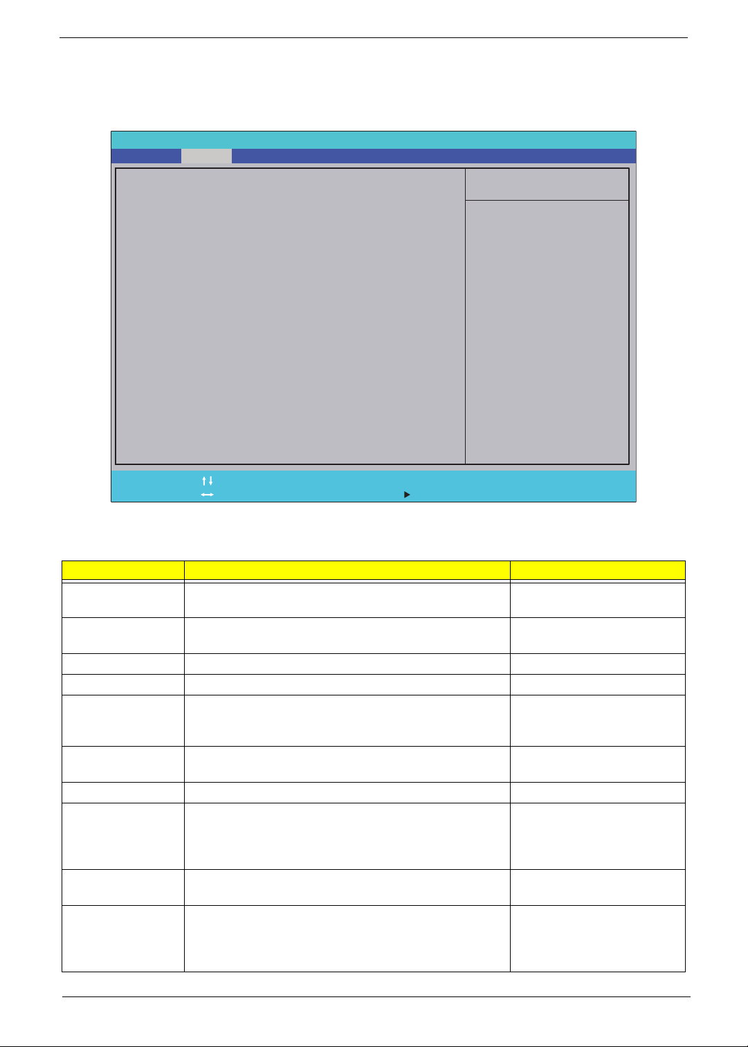
The Main screen allows the user to set the system time and date as well as enable and disable boot options
and recovery.
InsydeH20 Setup Utility Rev. 3.5
Information
System Time:
System Time:
System Date:
System Date:
Total Memory:
Total Memory:
Video Memory:
Video Memory:
Quiet Boot
Quiet Boot
Network Boot
Network Boot
F12 Boot Menu
F12 Boot Menu
D2D Recovery
D2D Recovery
SATA Mode
SATA Mode
Display Mode
Display Mode
Main
Security
Boot
[19:10:59]
[19:10:59]
[2/22/2010]
[2/22/2010]
4096 MB
4096 MB
128 MB
128 MB
[Enabled]
[Enabled]
[Enabled]
[Enabled]
[Disabled]
[Disabled]
[Enabled]
[Enabled]
[AHCI Mode]
[AHCI Mode]
[Switchable Graphics]
[Switchable Graphics]
Exit
Item Specific Help
This is the help for the
hour field. Valid range
is from 0 to 23.
/INCREASE
REDUCE
: F5/F6
Help
F1
Exit
ESC
NOTE: The screen above is for your reference only. Actual values may differ.
The table below describes the parameters in this screen.
Parameter Description Format/Option
System Time Sets the system time. The hours are displayed with 24-
System Date Sets the system date. Format MM/DD/YYYY
Total Memory
Video Memory
Quiet Boot Quiet Boot replaces the customary technical messages
Network Boot Enables, disables the system boot from LAN (remote
F12 Boot Menu Enables, disables Boot Menu during POST. Option: Enabled or Enabled
D2D Recovery Enables, disables D2D Recovery function. The function
SATA Mode Control the mode in which the SATA controller should
Display Mode Control the graphics display mode.
Select Item
Select Menu
hour format.
Displays the total memory available.
Displays the available memory for Video.
during POST with a more visually pleasing and
comfortable display (OEM Logo screen).
server).
allows the user to create a hidden partition on hard disc
drive to store operation system and restore the system
to factory defaults.
operate.
Note: Switchable Graphis is displayed as an option if
supported by the system.
F5/F6
Enter
Change Values
Select SubMenu
Setup Default
F9
Save and Exit
F10
Format: HH:MM:SS
(hour:minute:second)
(month/day/year)
N/A
N/A
Option: Enabled or
Disabled
Option: Enabled or
Disabled
Option: Enabled or
Disabled
Option: AHCI Mode or IDE
Mode
Options: Integrated
Graphics, Discrete
Graphics or Switchable
Graphics
Chapter 2 23
Page 34
Security
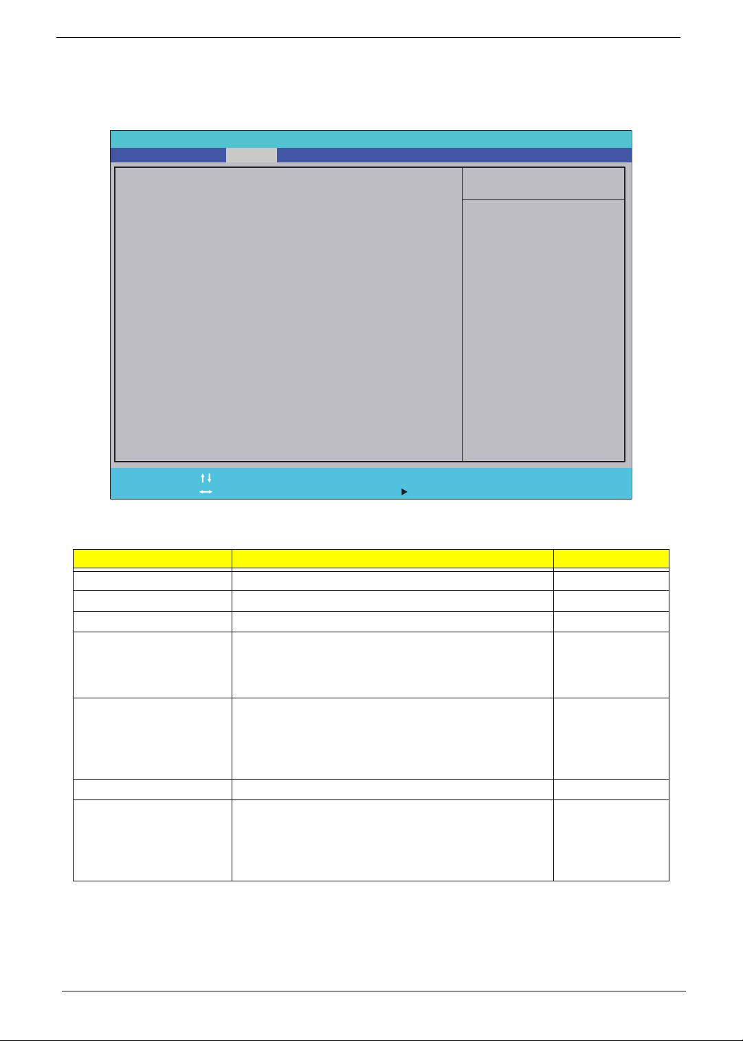
The Security screen contains parameters that help safeguard and protect your computer from unauthorized
use.
InsydeH20 Setup Utility Rev. 3.5
Information
Supervisor Password Is:
Supervisor Password Is:
User Password Is:
User Password Is:
HDD Password Is:
HDD Password Is:
Set Supervisor Password
Set Supervisor Password
Set User Password
Set User Password
Set HDD0 Password
Set HDD0 Password
Password on Password
Password on Password
Main Boot
Security
Exit
Clear
Clear
Clear
Clear
Clear
Clear
[Enabled]
[Enabled]
Item Specific Help
Install or Change the
password and the length
of password must be less
than eight words.
Help
F1
Exit
ESC
The table below describes the parameters in this screen. Settings in boldface are the default and suggested
parameter settings.
Parameter Description Option
Supervisor Password Is Shows the setting of the Supervisor password Clear or Set
User Password Is Shows the setting of the user password. Clear or Set
HDD0 Password Is Shows the setting of the hard disk password. Clear or Set
Set Supervisor Password Press Enter to set the supervisor password. When set,
Set User Password Press Enter to set the user password. When user
Set HDD Password Enter HDD Password. N/A
Password on Password Defines whether a password is required or not while the
Select Item
Select Menu
this password protects the BIOS Setup Utility from
unauthorized access. The user can not either enter the
Setup menu nor change the value of parameters.
password is set, this password protects the BIOS Setup
Utility from unauthorized access. The user can enter
Setup menu only and does not have right to change the
value of parameters.
events defined in this group happened. The following
sub-options are all requires the Supervisor password
for changes and should be grayed out if the user
password was used to enter setup.
F5/F6
Enter
Change Values
Select SubMenu
Setup Default
F9
Save and Exit
F10
N/A
N/A
Disabled or
Enabled
NOTE: When you are prompted to enter a password, you have three tries before the system halts. Don’t forget
your password. If you forget your password, you may have to return your notebook computer to your
dealer to reset it.
24 Chapter 2
Page 35
Setting a Password
Follow these steps as you set the user or the supervisor password:
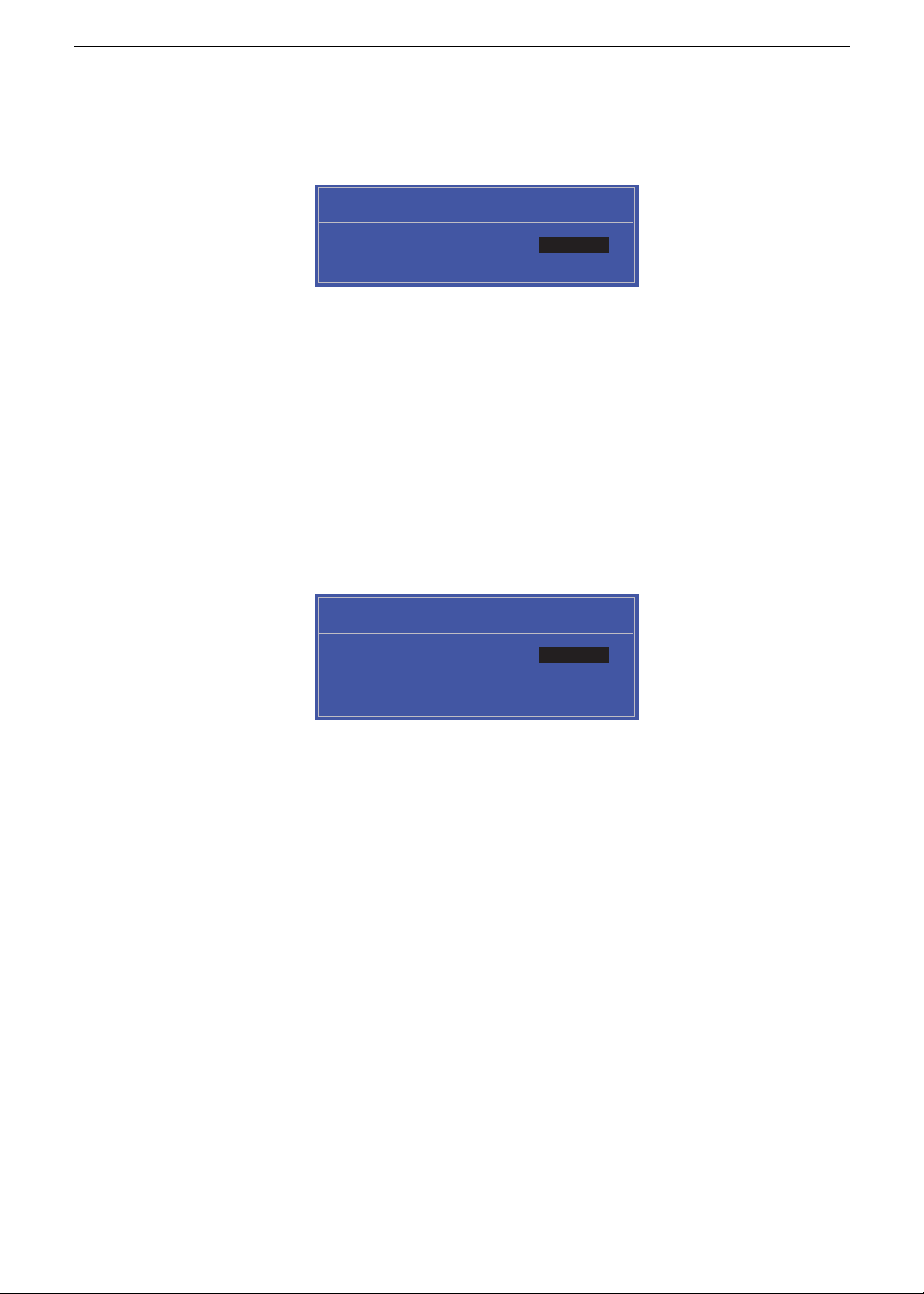
1. Use the ↑ and ↓ keys to highlight the Set Supervisor Password parameter and press the Enter key. The
Set Supervisor Password box appears:
Set Supervisor Password
Enter New Password [ ][ ]
Confirm New Password [ ]
2. Type a password in the “Enter New Password” field. The password length can not exceed 8 alphanumeric
characters (A-Z, a-z, 0-9, not case sensitive). Retype the password in the “Confirm New Password” field.
IMPORTANT:Be very careful when typing your password because the characters do not appear on the screen.
3. Press Enter. After setting the password, the computer sets the User Password parameter to “Set”.
4. If desired, you can opt to enable the Password on boot parameter.
5. When you are done, press F10 to save the changes and exit the BIOS Setup Utility.
Removing a Password
Follow these steps:
1. Use the ↑ and ↓ keys to highlight the Set Supervisor Password parameter and press the Enter key. The
Set Password box appears:
Set Supervisor Password
Enter Current Password [ ][ ]
Enter New Password [ ]
Confirm New Password [ ][ ]
2. Type the current password in the Enter Current Passwor d fi el d an d press Enter.
3. Press Enter twice without typing anything in the Enter New Password and Confirm New Password fields.
The computer then sets the Supervisor Password parameter to “Clear”.
4. When you have changed the settings, press u to save the changes and exit the BIOS Setup Utility.
Chapter 2 25
Page 36
Changing a Password
1. Use the ↑ and ↓ keys to highlight the Set Supervisor Password parameter and press the Enter key. The
Set Password box appears.
Set Supervisor Password
Enter Current Password [ ][ ]
Enter New Password [ ]
Confirm New Password [ ][ ]
2. Type the current password in the Enter Current Passwor d fi el d an d press Enter.
3. Type a password in the Enter New Password field. Retype the password in the Confirm New Password
field.
4. Press Enter. After setting the password, the computer sets the User Password parameter to “Set”.
5. If desired, you can enable the Password on boot parameter.
6. When you are done, press F10 to save the changes and exit the BIOS Setup Utility.
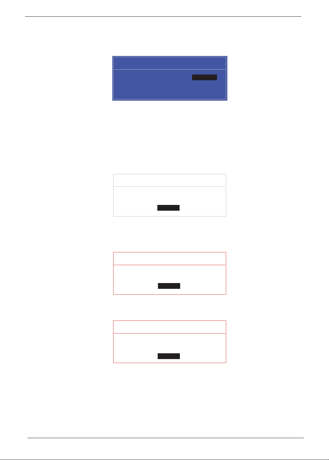
If the verification is OK, the screen will display as following.
Setup Notice
Changes have been saved.
[Continue][Continue]
The password setting is complete after the user presses Enter.
If the current password entered does not match the actual current password, the screen will show you the
Setup Warning.
Setup Warning
Invalid Password.
[Continue][Continue]
If the new password and confirm new password strings do not match, the screen will display the following
message.
Setup Warning
Passwords do not match.
Re-enter password.
[Continue][Continue]
26 Chapter 2
Page 37
Boot
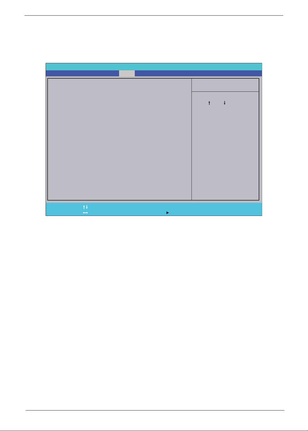
This menu allows the user to decide the order of boot devices to load the operating system. Bootable devices
includes the USB diskette drives, the onboard hard disk drive and the DVD drive in the module bay.
Select Boot Devices to select specific devices to support boot.
InsydeH20 Setup Utility Rev. 3.5
Information
Boot priority order:
Boot priority order:
Main Boot
Security
Exit
Item Specific Help
1. IDE0 : TOSHIBA MK3265GSX
1. IDE0 : TOSHIBA MK3265GSX
2. IDE1 : TSSTcorp CDDVDW TS-L633C
2. IDE1 : TSSTcorp CDDVDW TS-L633C
3. USB FDD :
3. USB FDD :
4. Network Boot : LEGACY PCI DEVICE
4. Network Boot : LEGACY PCI DEVICE
5. USB HDD :
5. USB HDD :
6. USB CDROM :
6. USB CDROM :
F1
ESC
Help
Exit
Select Item
Select Menu
F5/F6
Enter
Change Values
Select SubMenu
Use < > or < > to select
a device, then press
<F5> to move it down the
list, or <F6> to move
it up the list. Press
<Esc> to escape the menu
Setup Default
F9
Save and Exit
F10
Chapter 2 27
Page 38
Exit
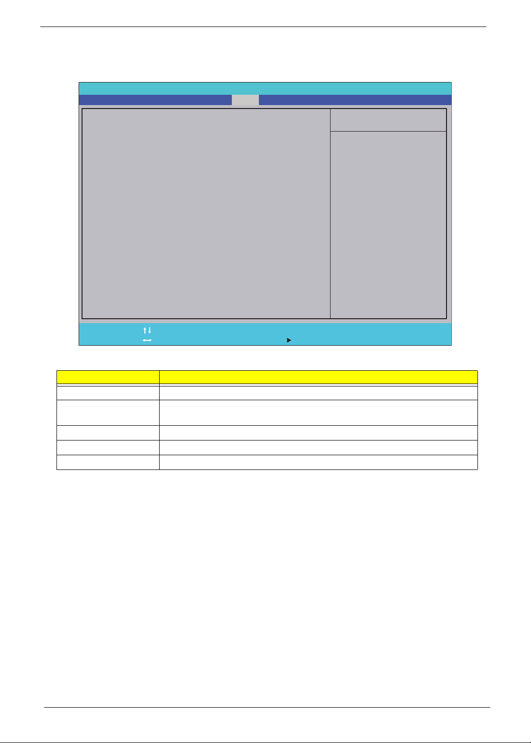
The Exit screen allows you to save or discard any changes you made and quit the BIOS Utility.
InsydeH20 Setup Utility Rev. 3.5
Information
Exit Saving Changes
Exit Saving Changes
Exit Discarding Changes
Exit Discarding Changes
Load Setup Defaults
Load Setup Defaults
Discard Changes
Discard Changes
Save Changes
Save Changes
Main Boot
Security
Exit
Item Specific Help
Exit System Setup and
save your changes.
Help
F1
Exit
ESC
The table below describes the parameters in this screen.
Parameter Description
Exit Saving Changes Exit System Setup and save your changes.
Exit Discarding
Changes
Load Setup Default Load default values for al l SETUP ite m.
Discard Changes Load previous values for all SETUP items.
Save Changes Save Setup Data.
Select Item
Select Menu
Exit utility without saving setup data.
F5/F6
Enter
Change Values
Select SubMenu
Setup Default
F9
Save and Exit
F10
28 Chapter 2
Page 39

BIOS Flash Utilities
The BIOS flash memory update is required for the following conditions:
• New versions of system programs
• New features or options
• Restore a BIOS when it becomes corrupted.
Use the Flash utility to update the system BIOS Flash ROM.
NOTE: If you do not have a crisis recovery diskette at hand, then you should create a Crisis Recovery
Diskette before you use the Flash utility.
NOTE: Do not install memory-related drivers (XMS, EMS, DPMI) when you use the Flash.
NOTE: Please use the AC adaptor power supply when you run the Flash utility. If the battery pack does not
contain enough power to finish BIOS Flash, you may not boot the system because the BIOS is not
completely loaded.
Fellow the steps below to run the Flash.
1. Prepare a bootable diskette.
2. Copy the Flash utilities to the bootable diskette.
3. Then boot the system from the bootable diskette. The Flash utility has auto-execution function.
Chapter 2 29
Page 40
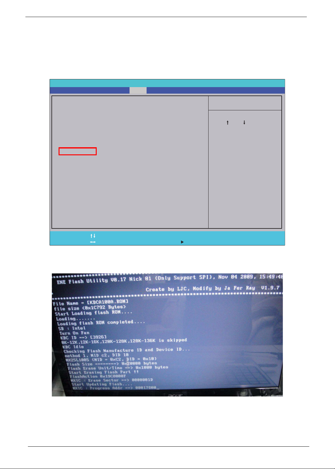
DOS Flash Utility
Perform the following steps to use the DOS Flash Utility:
1. Press F2 during boot to enter the Setup Menu.
2. Select Boot Menu to modify the boot priority order, for example, if using USB HDD to Update BIOS, move
USB HDD to position 1.
InsydeH20 Setup Utility Rev. 3.5
Information
Boot priority order:
Boot priority order:
Main Boot
Security
Exit
Item Specific Help
1. IDE0 : TOSHIBA MK3265GSX
1. IDE0 : TOSHIBA MK3265GSX
2. IDE1 : TSSTcorp CDDVDW TS-L633C
2. IDE1 : TSSTcorp CDDVDW TS-L633C
3. USB FDD :
3. USB FDD :
4. Network Boot : LEGACY PCI DEVICE
4. Network Boot : LEGACY PCI DEVICE
5. USB HDD :
5. USB HDD :
6. USB CDROM :
6. USB CDROM :
Help
F1
Exit
ESC
3. Execute the BIOS.BAT batch file to update BIOS.
The flash process begins as shown.
Select Item
Select Menu
F5/F6
Enter
Change Values
Select SubMenu
Use < > or < > to select
a device, then press
<F5> to move it down the
list, or <F6> to move
it up the list. Press
<Esc> to escape the menu
Setup Default
F9
Save and Exit
F10
30 Chapter 2
Page 41

4. In flash BIOS, the message Please do not remove AC Power Source displays.
NOTE: If the AC power is not connected, the following message displays.
Plug in the AC power to continue.
5. Flash is complete when the message Flash programming complete displays.
Chapter 2 31
Page 42
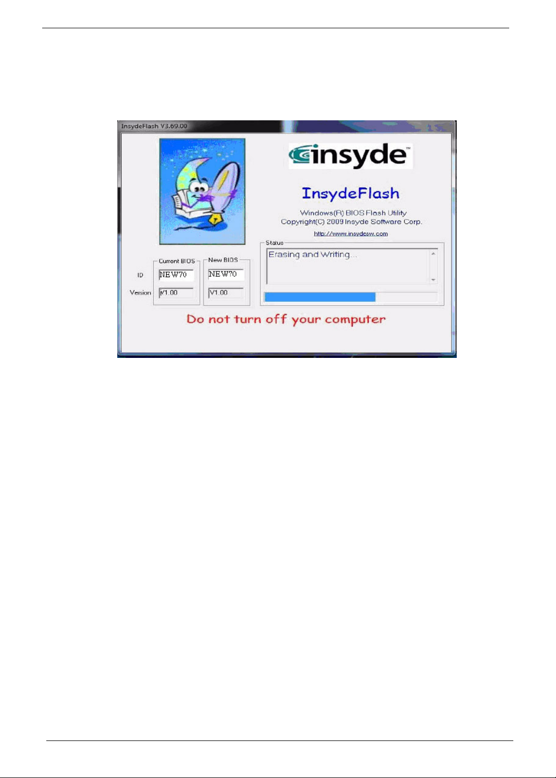
WinFlash Utility
Perform the following steps to use the WinFlash Utility:
1. Double-click the WinFlash executable.
2. Click OK to begin the update. A progress screen displays.
32 Chapter 2
Page 43
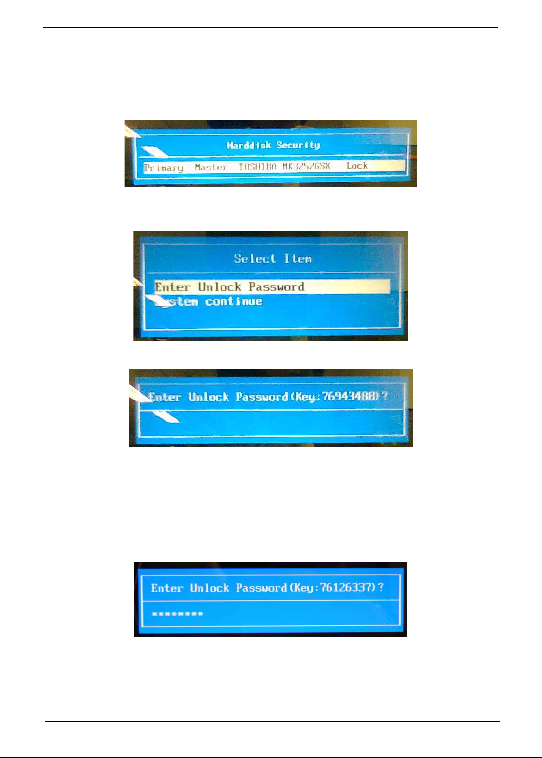
Remove HDD/BIOS Password Utilities
This section provides you with details about removing HDD/BIOS password:
Remove HDD Password:
If you key in the wrong HDD password three times, an error is generated.
To reset the HDD password, perform the following steps:
1. After the error is displayed, select the Enter Unlock Password option on th e screen.
2. An Encode key is generated for unlocking utilities. Note down this key.
3. Execute the UnlockHD.EXE file to create the unlock code in DOS Mode using the format UnlockHD
[Encode code] with the code noted in the previous step, as follows:
UnlockHD 76943488
4. The command generates a password which can be used for unlocking the HDD.
Password : 46548274
5. Key in the password from the previous step to unlock the HDD as shown.
Chapter 2 33
Page 44
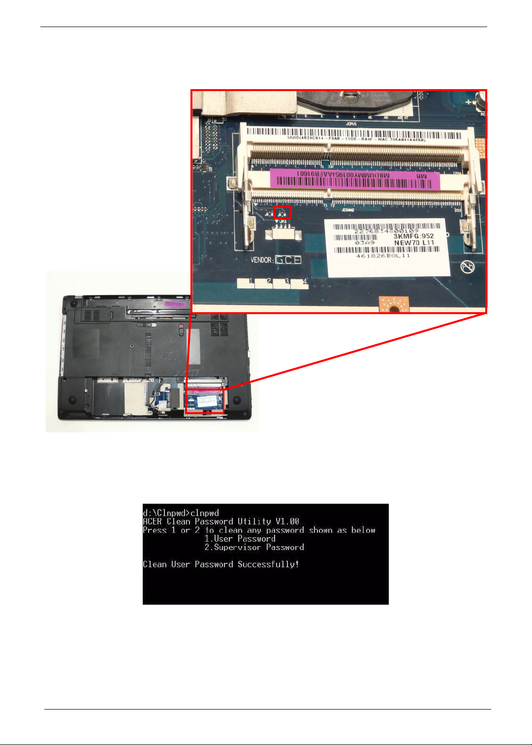
Removing BIOS Passwords:
To clear the User or Supervisor passwords, open the DIMM door and use a metal instrument to short the
RTC_RST point.
Cleaning BIOS Passwords
To clean the User or Supervisor passwords, perform the following steps:
1. From a DOS prompt, execute clnpwd.exe
2. Press 1 or 2 to clean the desired password shown on the screen.
The onscreen message determines whether the function is successful or not.
34 Chapter 2
Page 45
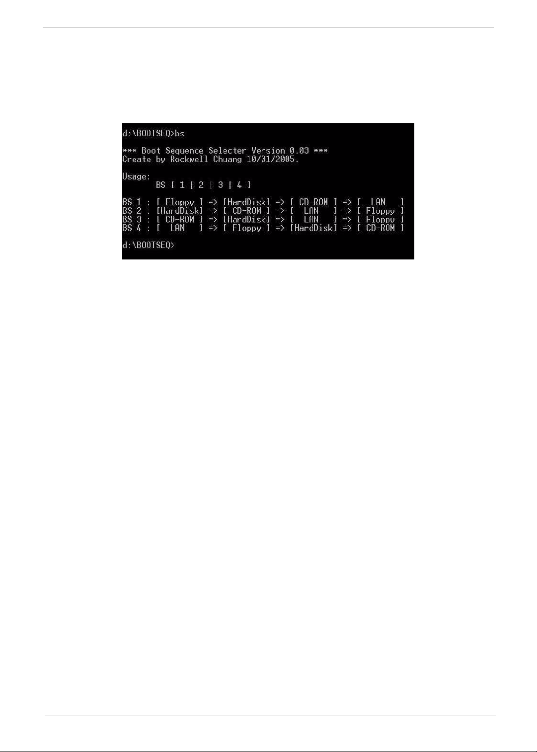
Using Boot Sequence Selector
The Boot Sequence Selector allows the boot order to be changed without accessing the BIOS. To use Boot
Sequence Selector, perform the following steps:
1. Enter into DOS.
2. Execute BS.exe to display the usage screen.
3. Select the desired boot sequence by entering the corresponding sequence. For example, enter BS2 to
change the boot sequence to HDD | CD ROM | LAN | Floppy.
Chapter 2 35
Page 46

Using DMITools
The DMI (Desktop Management Interface) Tool copies BIOS information to EEPROM to be used in the DMI
pool for hardware management.
When the BIOS displays Verifying DMI poo l data it is checking that the table correlates with the hardware
before sending to the operating system (Windows, etc.).
To update the DMI Pool, perform the following steps:
1. Boot into DOS.
2. Execute dmitools. The following messages report to screen to confirm completion:
• dmitools /r ==> Read dmi string from bios
• dmitools /wm xxxx ==> Write manufacturer name to eeprom (max. 16 characters)
• dmitools /wp xxxx ==> Write product name to eeprom (max. 16 characters)
• dmitools /ws xxxx ==> Write serial number to eeprom (max. 22 characters)
• dmitools /wu xxxx ==> Write uuid to eeprom
• dmitools /wa xxxx ==> Write asset tag to eeprom (max. 32 characters)
The following examples show the commands and the corresponding output information.
Read DMI Information from Memory
Input:
dmitools /r
Output:
Manufacturer (Type1, Offset04h): Acer
Product Name (Type1, Offset05h): TravelMate xxxxx
Serial Number (Type1, Offset07h): 01234567890123456789
UUID String (Type1, Offset08h): xxxxxxxx-xxxx-xxxx-xxxx-xxxxxxxxxxxx
Asset Tag (Type3, Offset04h): Acet Asstag
Write Product Name to EEPROM
Input:
dmitools /wp Acer
Write Serial Number to EEPROM
Input:
dmitools /ws 01234567890123456789
4 ). Write UUID to EEPROM ( Create UUID from Intel WFM20.pdf )
Input:
dmitools /wu
5). Write Asset Tag to EEPROM
Input:
dmitools /wa Acet Asstag
NOTE: When using any of the Write options, restart the system to make the new DMI data effective.
36 Chapter 2
Page 47
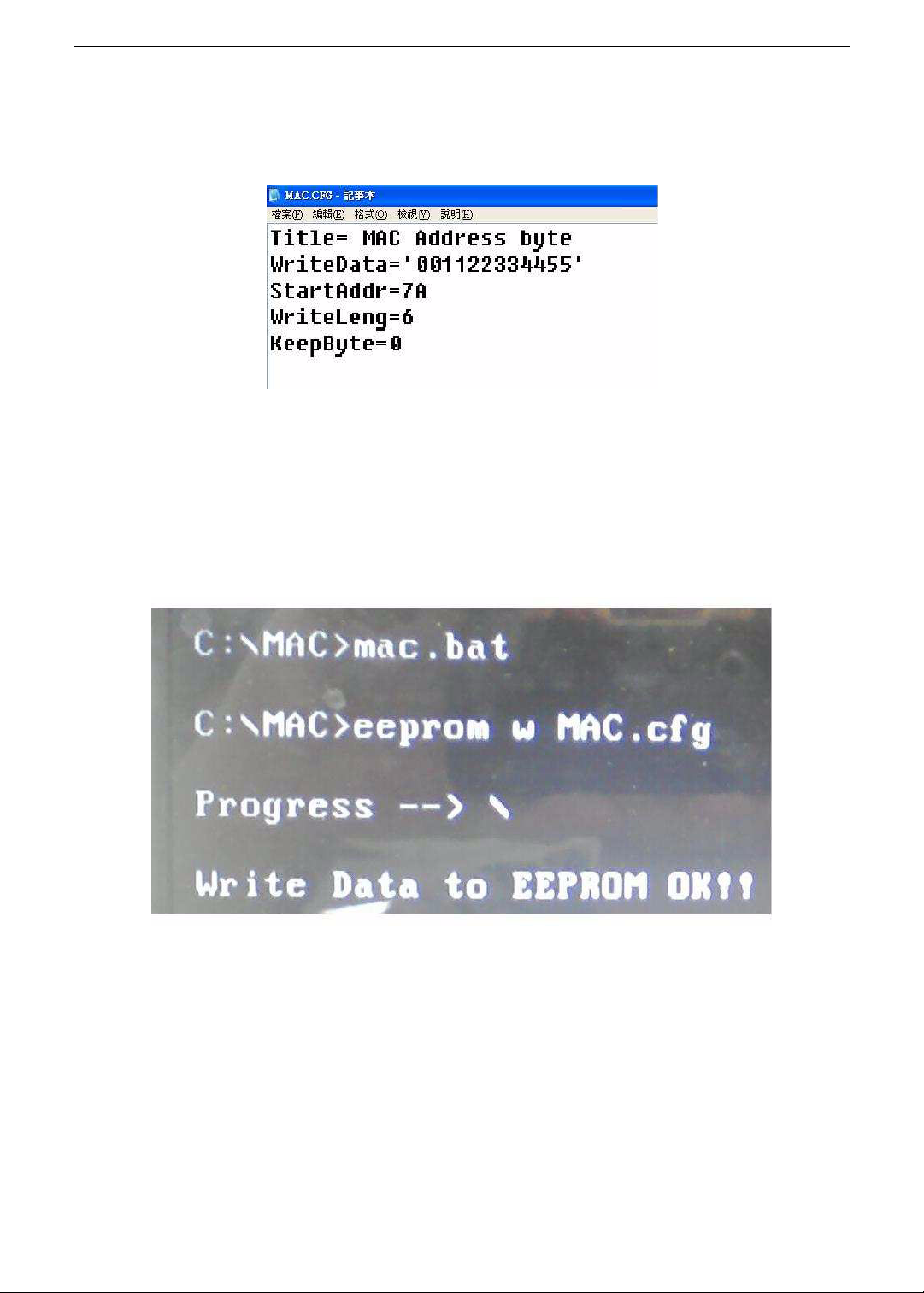
Using the LAN MAC EEPROM Utility
You can use the MAC.BAT utility to write the MAC.CFG file to the EEPROM under DOS mode.
1. Use a text editor (for example: Notepad) to open the MAC.CFG file. You can see the MAC.CFG contents
as below:
WriteData = ‘001122334455' MAC value
StartAddr=7A MAC address
WriteLeng=6 MAC value length
KeepByte=0 don’t care
2. In DOS mode, run the MAC.BAT file to write MAC values to eeprom.
Chapter 2 37
Page 48

38 Chapter 2
Page 49

Machine Disassembly and Replacement
IMPORTANT: The outside housing and color may vary from the mass produced model.
This chapter contains step-by-step procedures on how to disassemble the notebook computer for
maintenance and troubleshooting.
Disassembly Requirements
To disassemble the computer, you need the following tools:
• Wrist grounding strap and conductive mat for preventing electrostatic discharge
• Flat screwdriver
• Philips screwdriver
• Plastic flat screwdriver
• Plastic tweezers
NOTE: The screws for the different components vary in size. During the disassembly process, group the
screws with the corresponding components to avoid mismatch when putting back the components.
Chapter 3
Chapter 3 39
Page 50
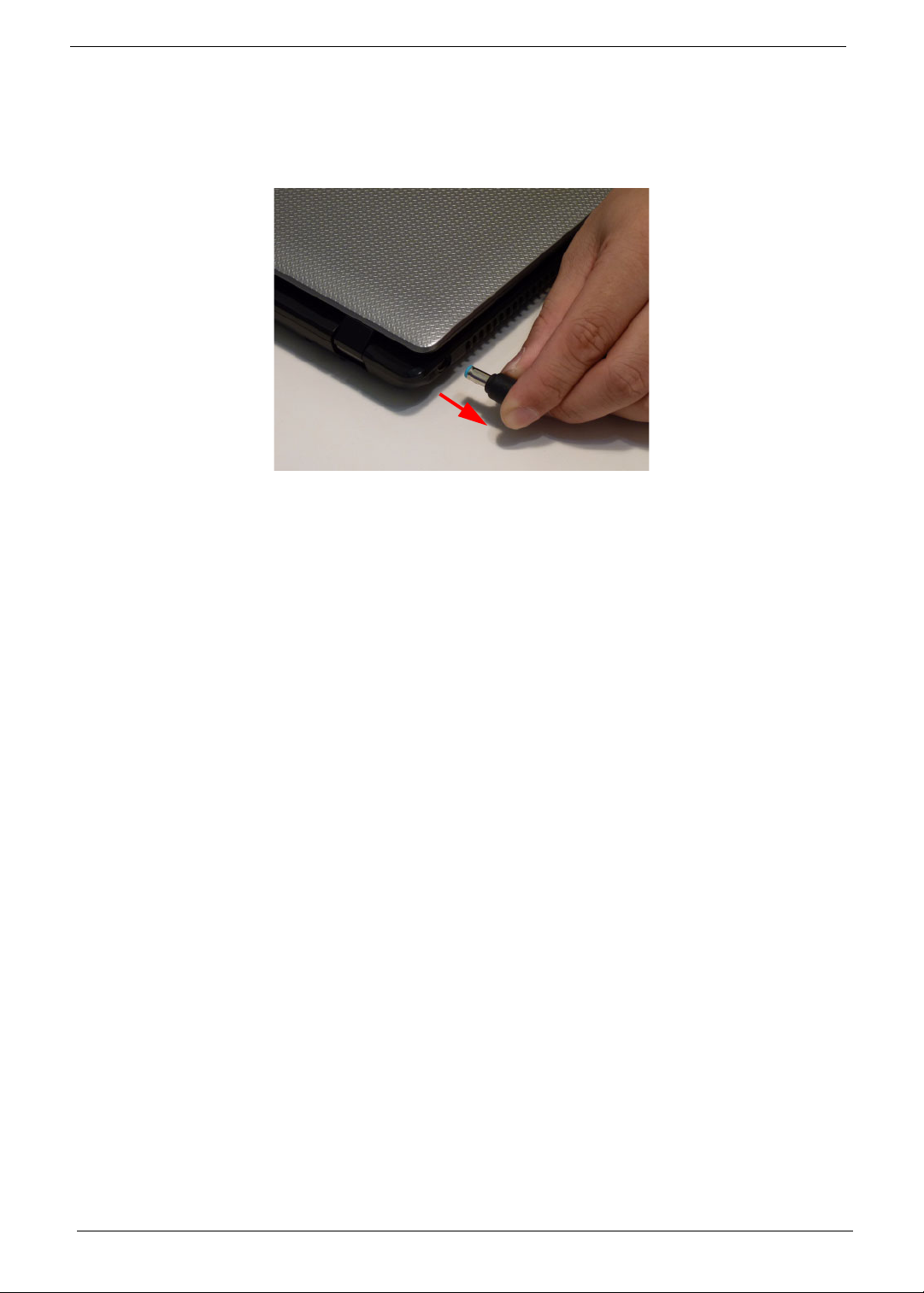
Pre-disassembly Instructions
Before proceeding with the disassembly procedure, make sure that you do the following:
1. Turn off the power to the system and all peripherals.
2. Unplug the AC adapter and all power and signal cables from the system.
3. Place the system on a flat, stable surface.
4. Remove the battery pack.
40 Chapter 3
Page 51
Disassembly Process
IMPORTANT: The LCD Module cannot be disassembled outside of factory conditions. If any part of the LCD
Module is faulty, such as the camera, antenna or LCD panel, the whole module must be replaced.
The disassembly process is divided into the following stages:
• External module disassembly
• Main unit disassembly
• LCD module disassembly
The flowcharts provided in the succeeding disassembly sections illustrate the entire disassembly sequence.
Observe the order of the sequence to avoid damage to any of the hardware components. For example, if you
want to remove the mainboard, you must first remove the keyboard, then disassemble the inside assembly
frame in that order.
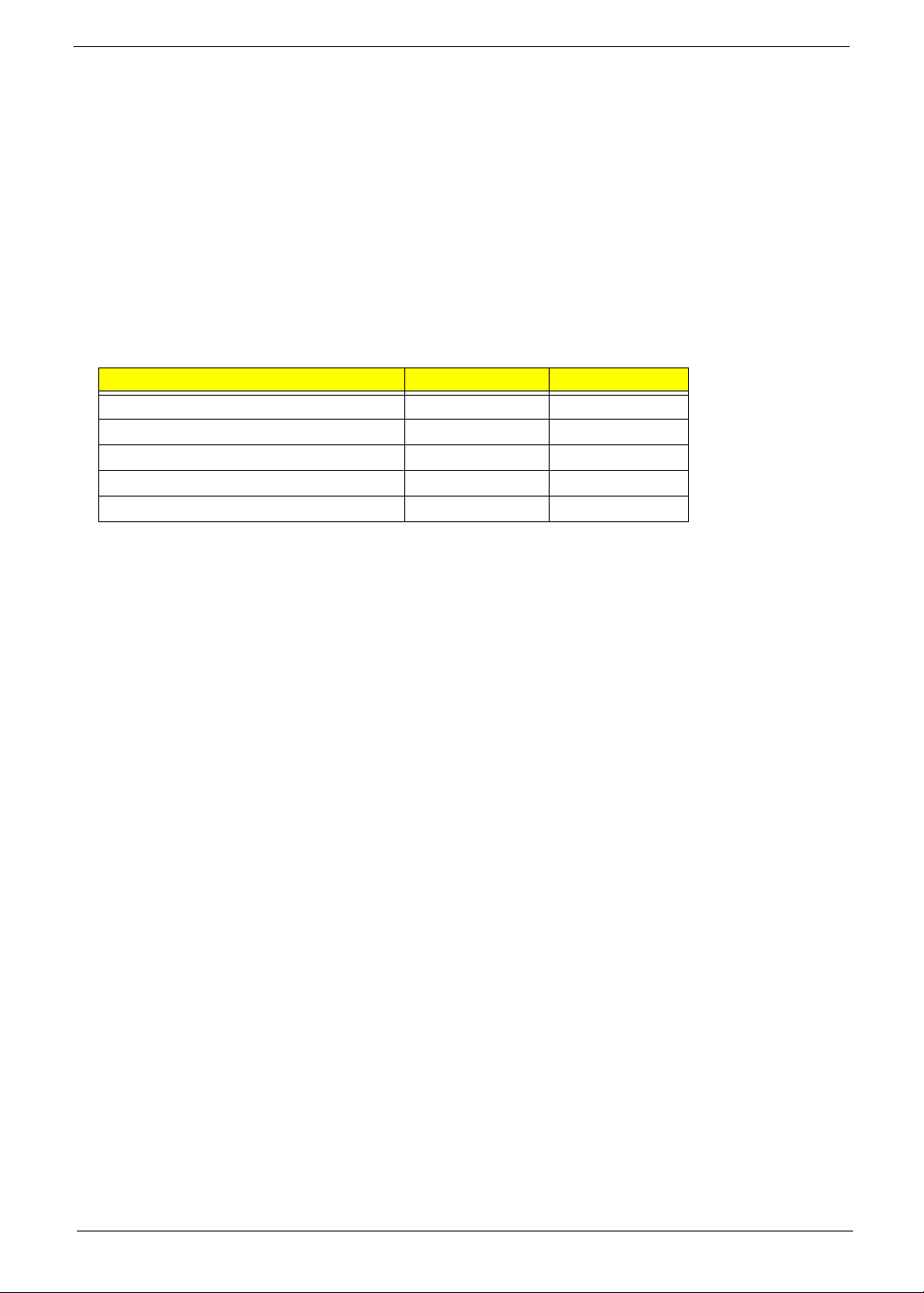
Main Screw List
Screw Quantity Part Number
M2.5*8 19 86.PSV02.002
M2*3 26 86.PSV02.004
M2.5*5 8 86.PSV02.001
M1.98*3 4 86.PSV02.004
M2.5*6 4 86.PSV02.003
Chapter 3 41
Page 52
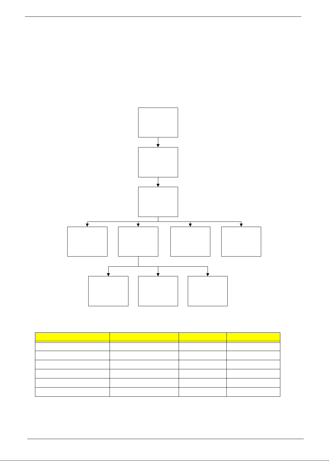
External Module Disassembly Process
IMPORTANT: The outside housing and color may vary from the mass produced model.
External Modules Disassembly Flowchart
The flowchart below gives you a graphic representation of the external module disassembly sequence and
instructs you on the components that need to be removed during servicing. For example, if you want to remove
the keyboard, you must first remove the switch board.
Turn off system
and peripherals
power
Disconnect power
and signal cables
from system
Remove
Battery
Remove
Dummy Card
Remove
DIMMs
Remove
HDD/WLAN/DIMM
Door
Remove
WLAN
Remove
3G Cover
Remove
HDD
Remove
ODD
Screw List
Step Screw Quantity Part No.
ODD Module M 2.5*8 1 86.PSV02.002
ODD Bracket M2*3 2 86.PSV02.004
3G Cover M2.5*8 1 86.PSV02.002
Logic Lower Door M2.5*8 2 86.PSV02.002
WLAN Module M2*3 1 86.PSV02.004
HDD Carrier M2*3 4 86.PSV02.004
42 Chapter 3
Page 53
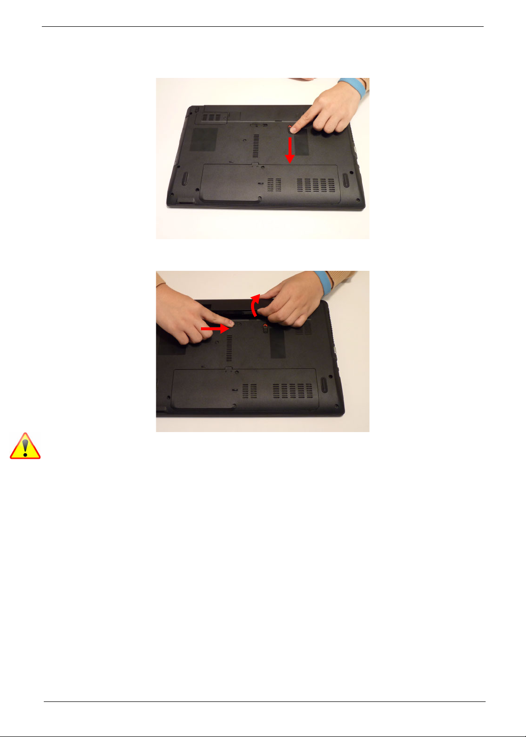
Removing the Battery Pack
1. Turn computer over. Slide the battery lock in the direction shown.
2. Slide and hold the battery release latch to the release position (1), then lift out the battery pack from the main
unit (2).
2
1
NOTE: Please follow local regulations for disposal.
Chapter 3 43
Page 54
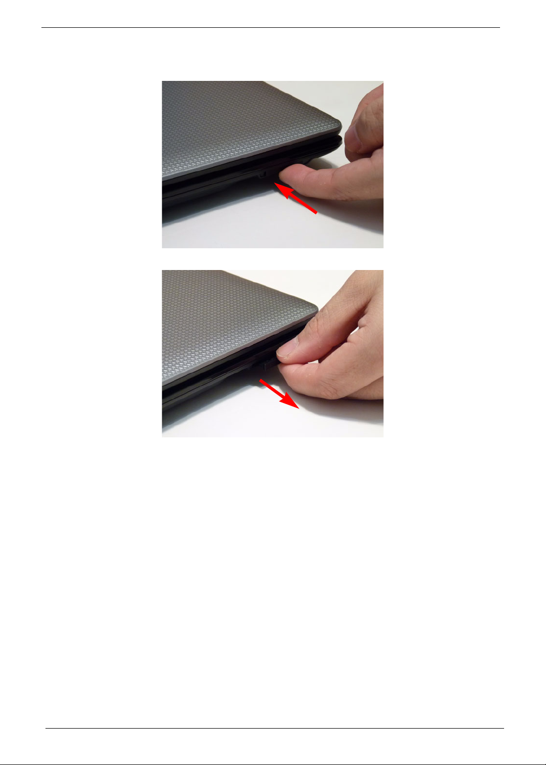
Removing the SD Dummy Card
1. Push the SD dummy card all the way in to eject it.
2. Pull it out from the slot.
44 Chapter 3
Page 55
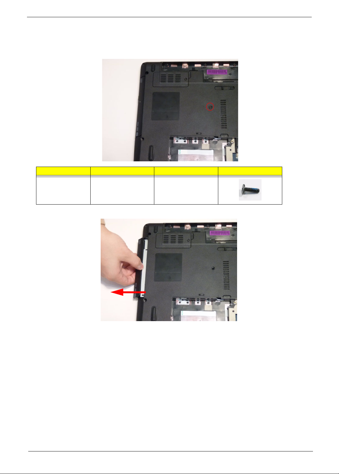
Removing the Optical Drive Module
1. See “Removing the Battery Pack” on page 43.
2. Remove the screw securing the ODD module.
Step Size Quantity Screw Type
ODD Module M2.5*8 1
3. Pull the optical drive module out from the chassis.
Chapter 3 45
Page 56
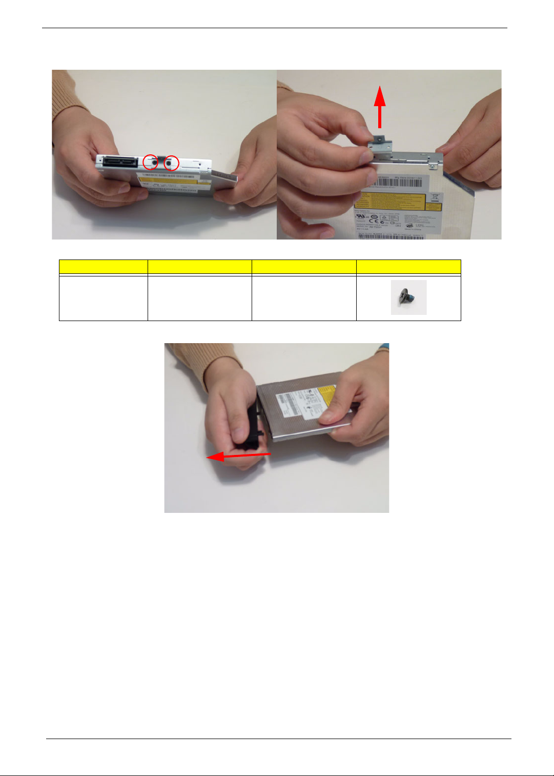
4. Remove the two (2) screws securing the ODD bracket and remove the ODD bracket from the optical disk drive
module.
Step Size Quantity Screw Type
ODD Bracket M2*3 2
5. Remove the ODD bezel by prying the top edge away and clear of the module.
46 Chapter 3
Page 57
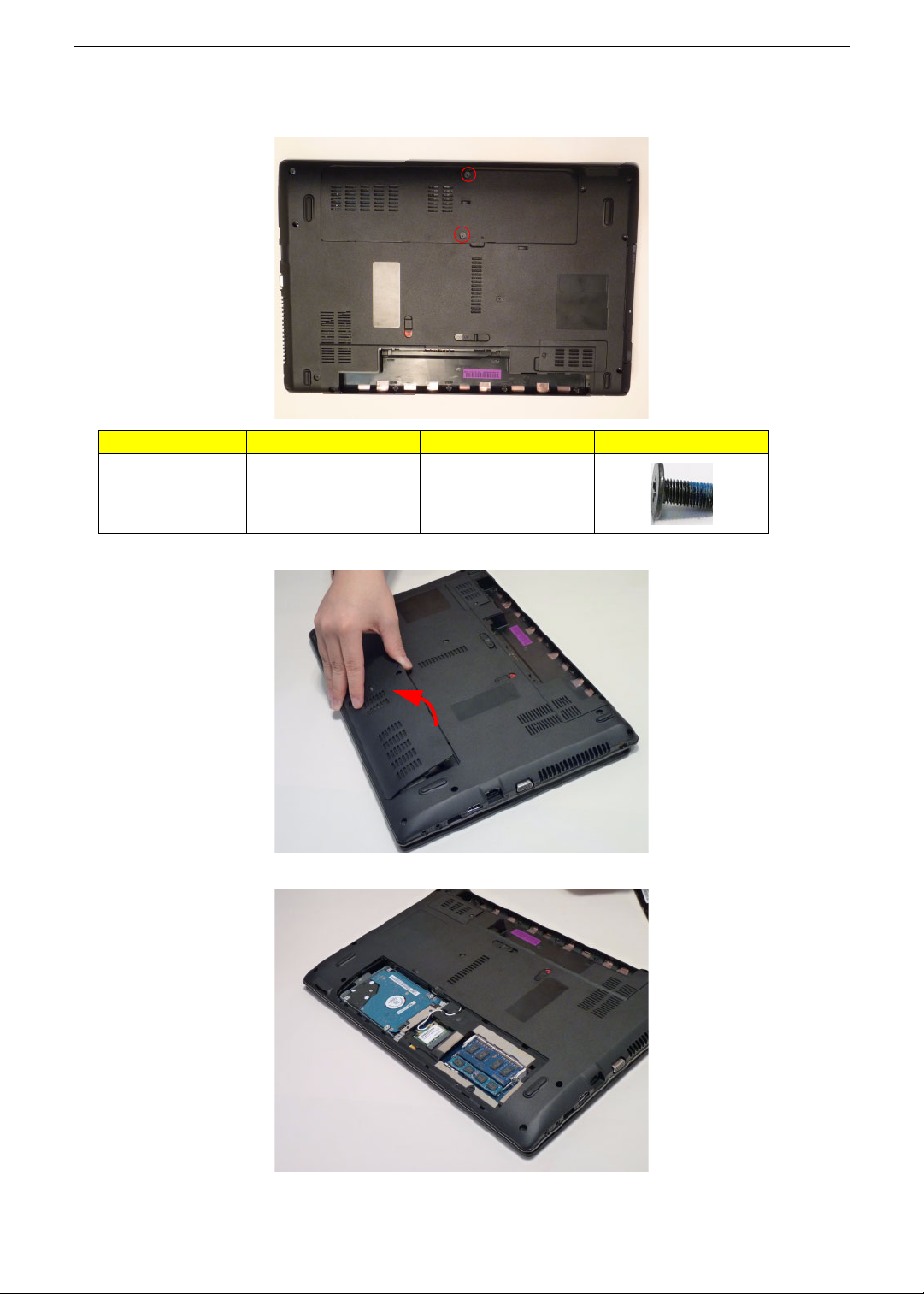
Removing the Logic Lower Door
1. Remove two (2) screws from the logic lower door.
Step Size Quantity Screw Type
Logic lower door M2.5*8 2
2. Lift the door beginning from the inner edge as shown.
3. Lift the door clear of the device, exposing the HDD, DIMM, and WLAN modules.
Chapter 3 47
Page 58
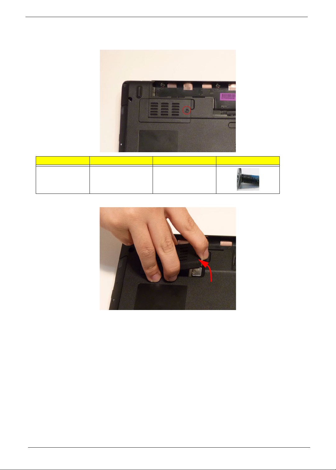
Removing the 3G Cover
1. Remove one (1) screw from the 3G Cover.
Step Size Quantity Screw Type
3G Cover M2.5*8 1
2. Lift the 3G Cover from the right edge first, then remove completely.
48 Chapter 3
Page 59
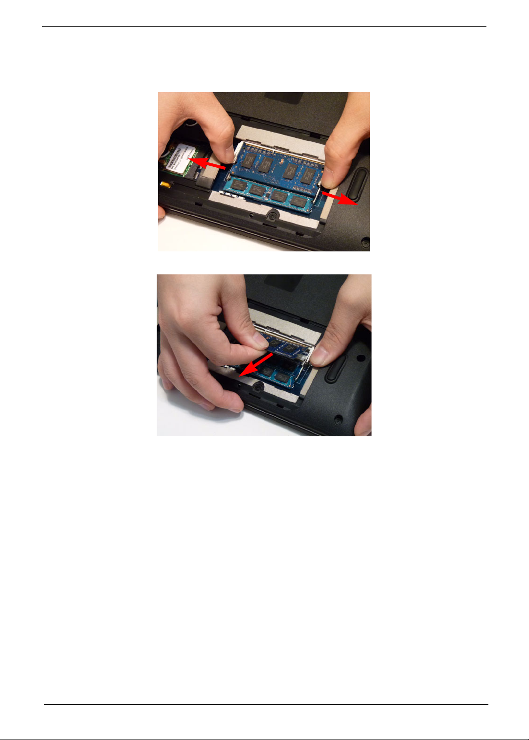
Removing the DIMM Module
1. See “Removing the Logic Lower Door” on page 47.
2. Push out the release latches on both sides of the DIMM socket to release the DIMM module.
3. Remove the DIMM module.
4. Repeat steps 2 and 3 for the second DIMM module if present.
Chapter 3 49
Page 60
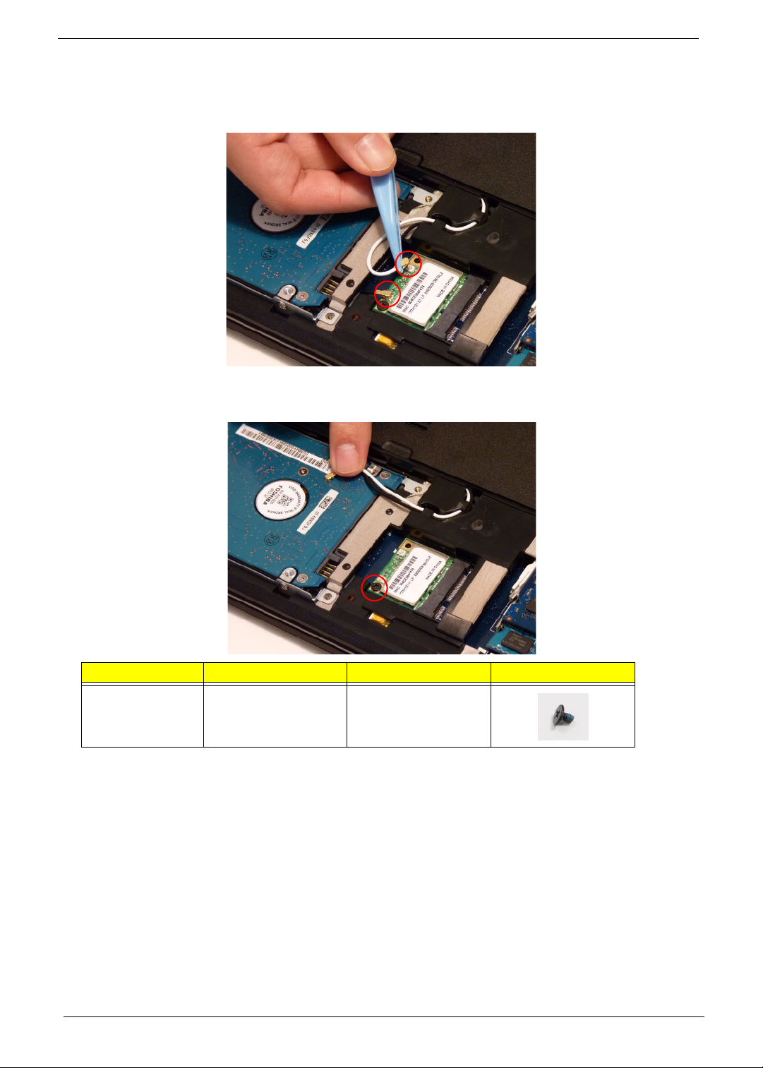
Removing the WLAN Module
1. See “Removing the Logic Lower Door” on page 47.
2. Disconnect the antenna cables from the WLAN Board.
NOTE: Cable placement is Black to the MAIN terminal and White to the AUX terminal.
3. Move the antenna away and remove the two (1) screws to release the WLAN Board.
Step Size Quantity Screw Type
WLAN Module M2*3 1
50 Chapter 3
Page 61
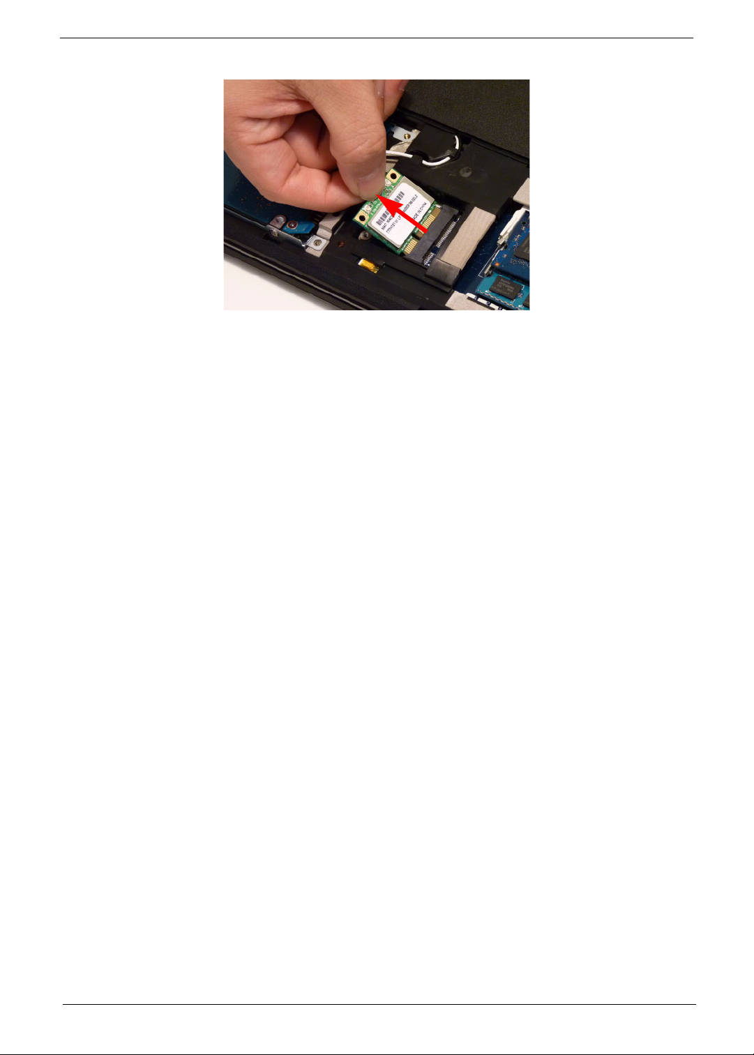
4. Detach the WLAN Board from the WLAN socket.
NOTE: When reattaching the antennas, ensure the cables are tucked into the chassis to prevent damage.
Chapter 3 51
Page 62
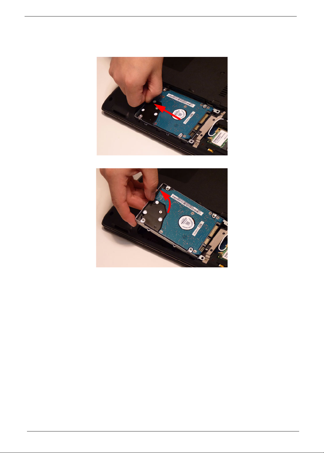
Removing the Hard Disk Drive Module
1. See “Removing the Logic Lower Door” on page 47.
2. Using the pull-tab, slide the HDD Module in the direction of the arrow to disconnect the interface.
3. Lift the HDD Module clear of the HDD bay.
NOTE: To prevent damage to device, avoid pressing down on it or placing heavy objects on top of it.
52 Chapter 3
Page 63
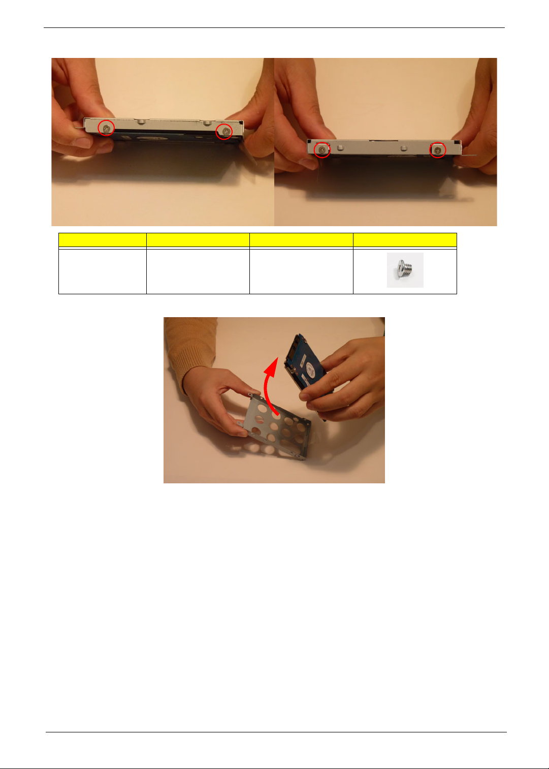
4. Remove the four (4) screws (two each side) securing the hard disk to the carrier.
Step Size Quantity Screw Type
HDD Carrier M3*3 4
5. Remove the HDD from the carrier.
Chapter 3 53
Page 64
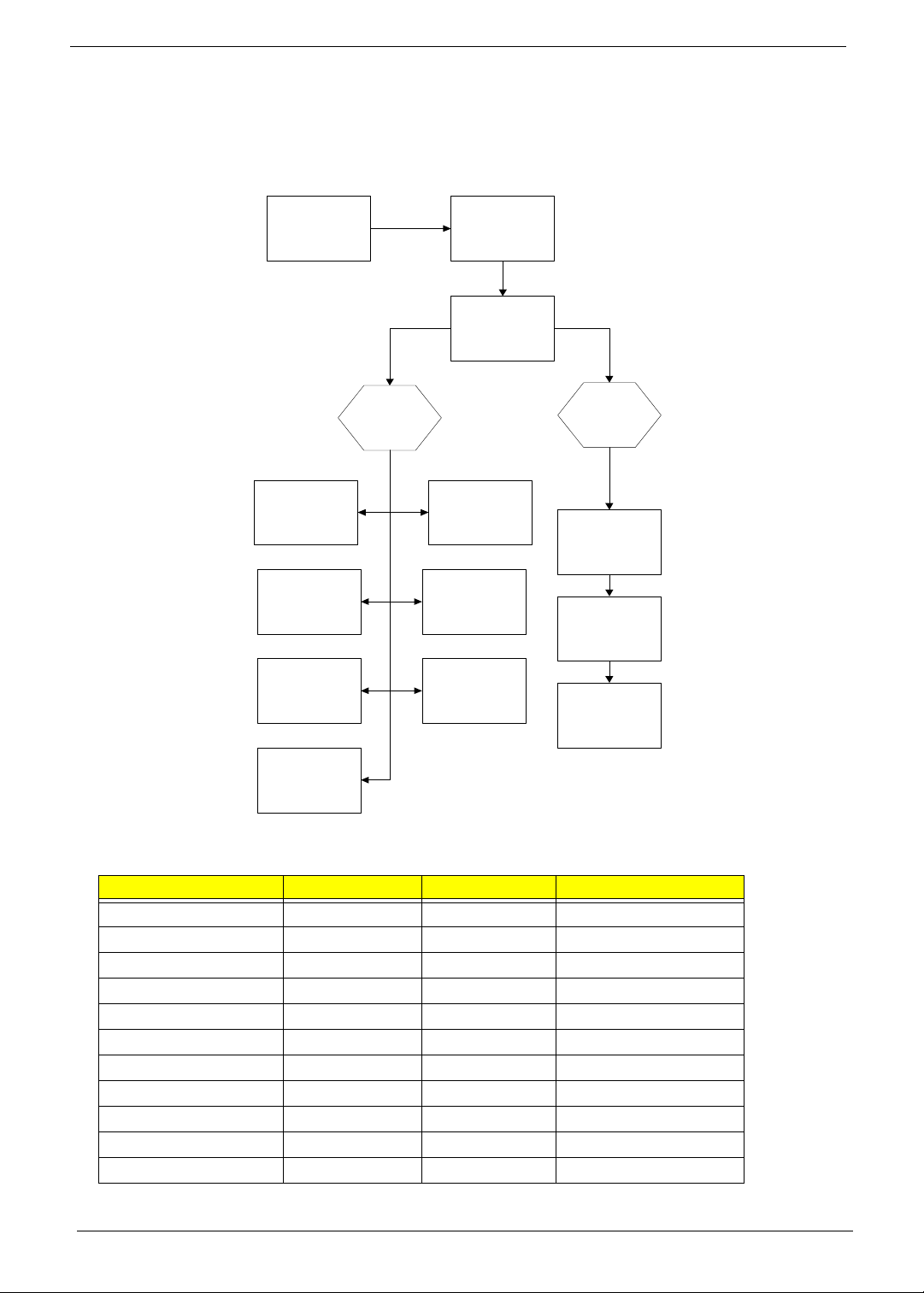
Main Unit Disassembly Process
Main Unit Disassembly Flowchart
Remove External
Modules before
proceeding
Remove
Power Board
Remove
Left Speaker
Module
Remove
Right Speaker
Module
Upper
Cover
Remove
Keyboard
Remove
Upper Cover
Remove
TouchPad
Bracket
Remove
USB Board
Remove
Card Reader
Board
Lower
Cover
Remove
Mainboard
Remove
Thermal Module
Remove
CPU
Remove
USB Board
Screw List
Step Screw Quantity Part No.
Upper Cover M2.5*5 7 86.PSV02.001
Lower Cover M2.5*8 11 86.PSV02.002
Battery Bay M2*3 4 86.PSV02.004
Left Speaker Module M2*3 2 86.PSV02.004
Right Speaker Module M2*3 2 86.PSV02.004
Power Board M2*3 2 86.PSV02.004
Card Reader M2*3 1 86.PSV02.004
USB Board M2*3 1 86.PSV02.004
TouchPad Bracket M2*3 1 86.PSV02.004
Mainboard M2.5*5 1 86.PSV02.001
Thermal Module M1.98*3 4 86.PSV02.006
54 Chapter 3
Page 65
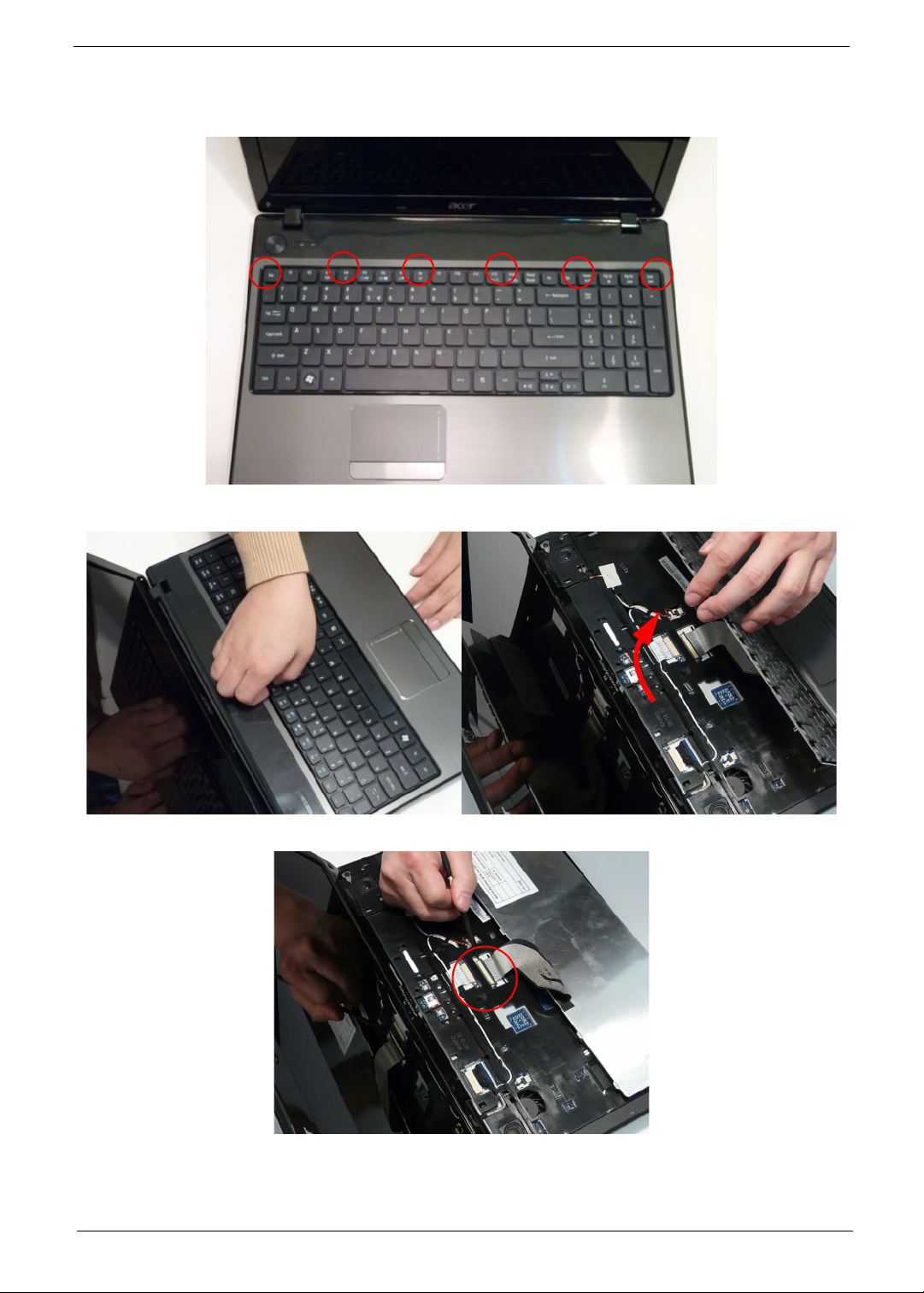
Removing the Keyboard
1. Unlock the six (6) keyboard locks.
2. Pry up the centre of the Keyboard and rotate it upward away from the Upper Cover.
3. Turn the keyboard over on to the TouchPad area to expose the FFC connector.
Chapter 3 55
Page 66
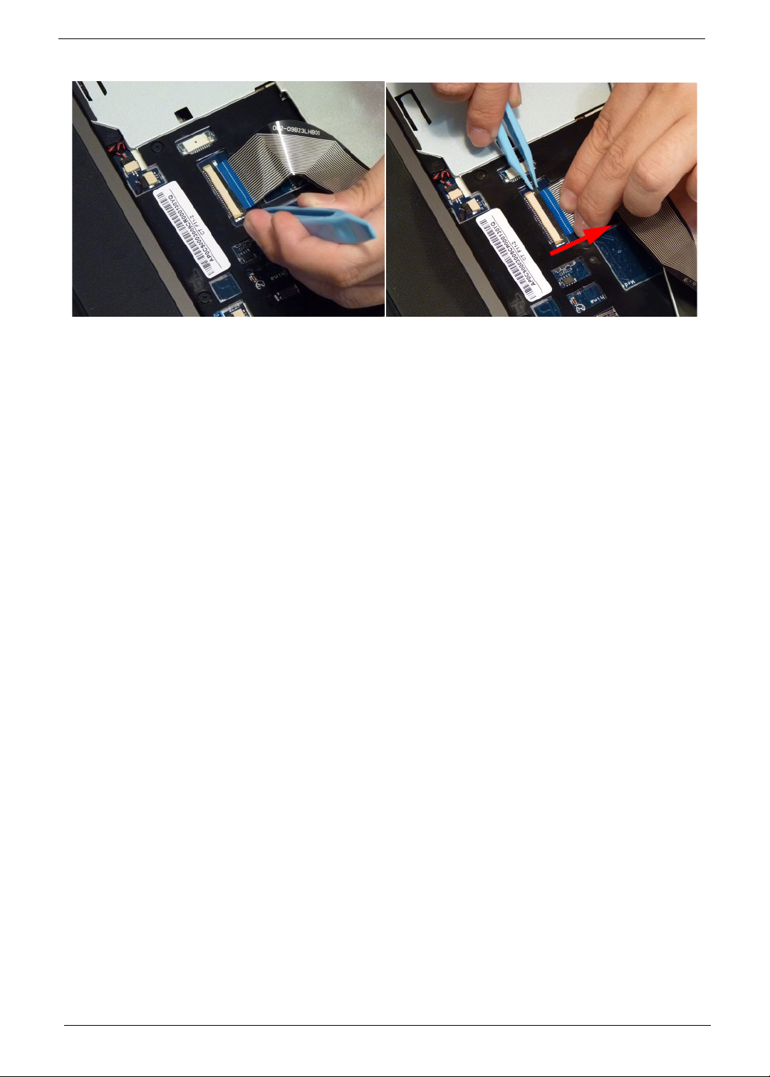
4. Open the locking latch and disconnect the FFC from the mainboard.
5. Lift the keyboard clear of the Upper Cover.
56 Chapter 3
Page 67
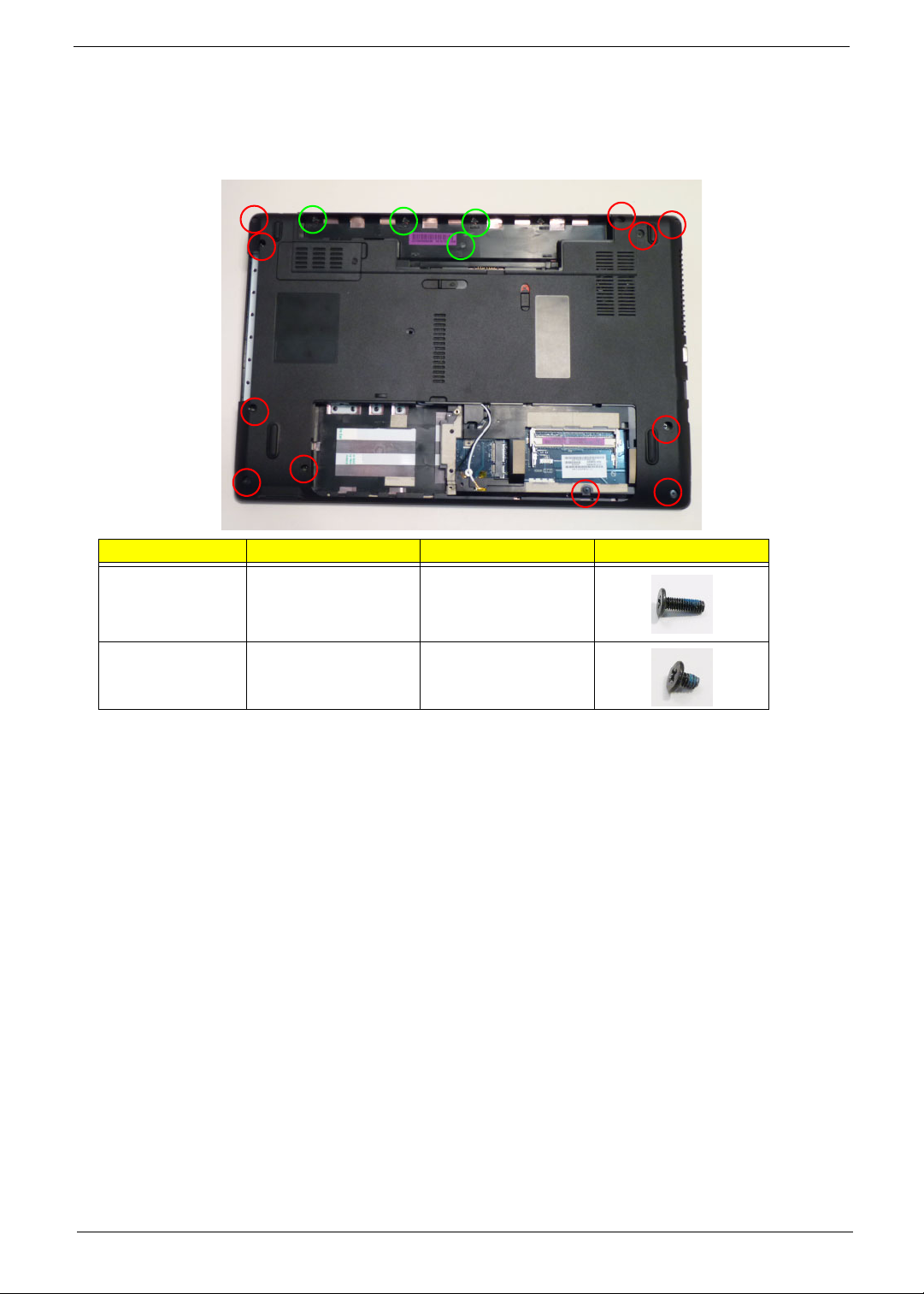
Removing the Upper Cover
1. See “External Module Disassembly Process” on page 42.
2. Turn the computer over. Remove the eleven (11) screws on the lower cover and four (4) screws from the
battery bay.
Step Size Quantity Screw Type
Upper Cover (red
callout)
M2.5*8 11
Battery Bay
(green callout)
M2*3 4
Chapter 3 57
Page 68
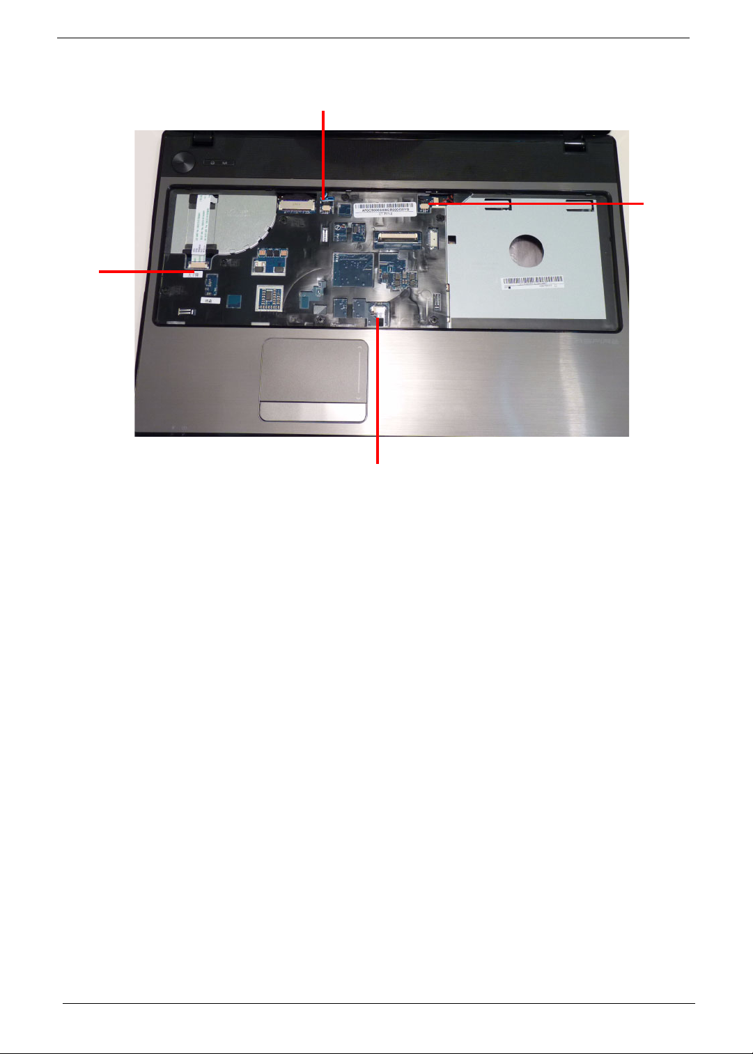
3. Turn the computer over and disconnect the following four (4) cables from the Mainboard.
B
A
C
D
58 Chapter 3
Page 69
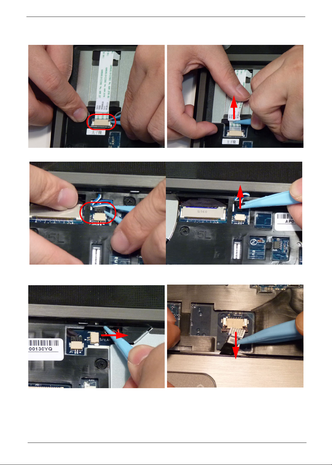
4. Release the locking latch on A. 5. Disconnect A as shown.
6. Release the locking latch on B and remove the ca ble as shown.
7. Release the locking latch on C and remove the
cable as shown.
NOTE: Avoid pulling on cables directly to prevent damage to the connectors.
NOTE: Use the pull-tabs on FFCs whenever available to prevent damage.
Chapter 3 59
8. Release the locking latch on D and remove the
cable as shown.
Page 70
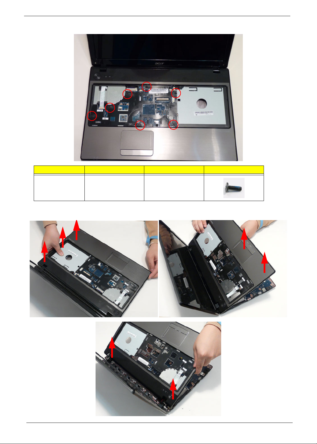
9. Remove the seven (7) screws on the Upper Cover as shown.
Step Size Quantity Screw Type
Upper Cover M2.5*5 7
10. Starting at the top right side of the cover, pry ap art the Upper and Lower Covers as shown. Work along the front
edge of the casing to the left as shown, then lift the Upper Cover clear of the Lower Cover.
60 Chapter 3
Page 71
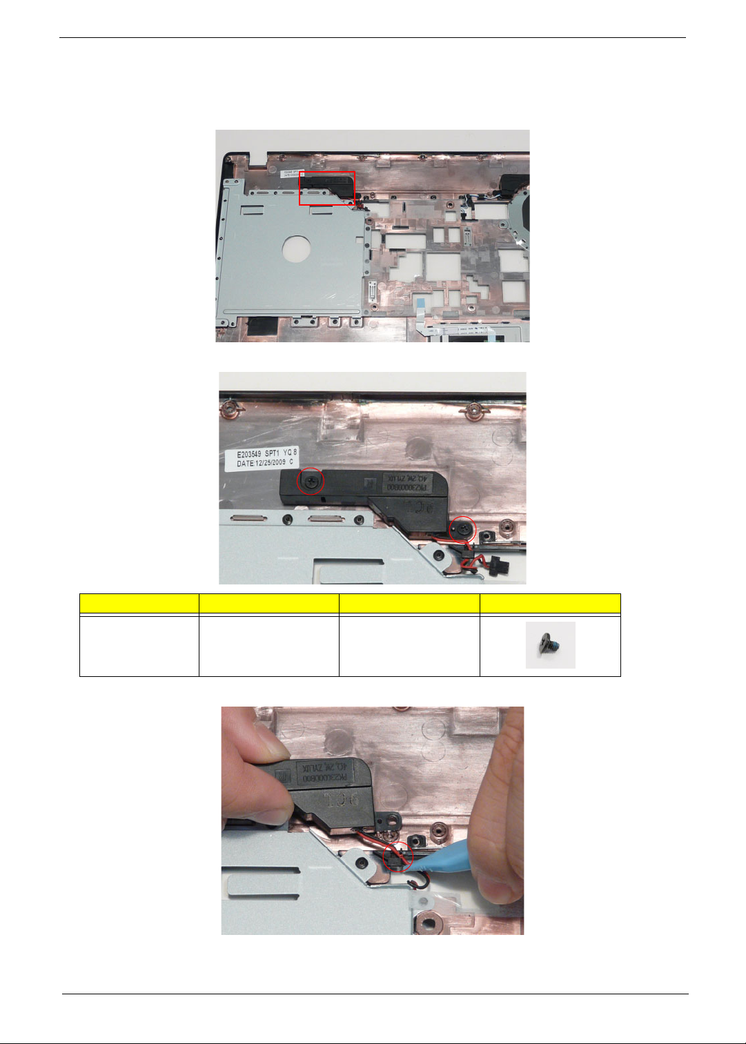
Removing the Left Speaker Module
1. See “Removing the Upper Cover” on page 57.
2. Locate the Left Speaker Module on the Upper Cover as shown.
3. Remove two (2) screws from the left speaker module.
Step Size Quantity Screw Type
Left Speaker
Module
4. Remove the Speaker cable from the cable channel. Ensure that the cable is free from all cable clips.
M2*3 2
Chapter 3 61
Page 72
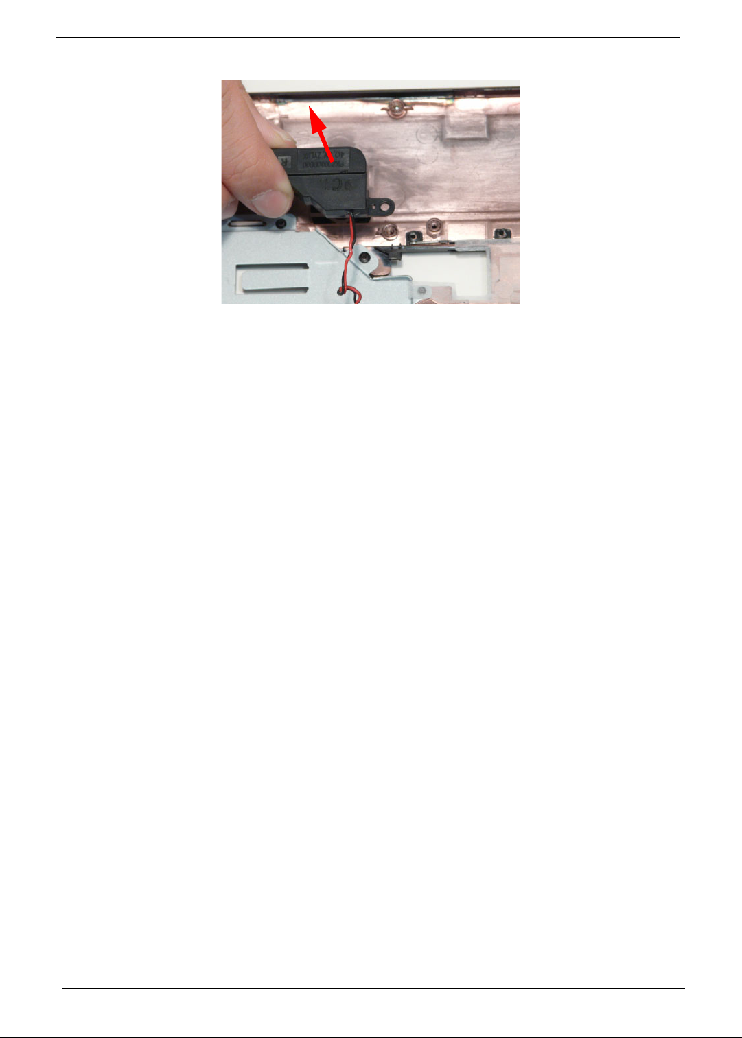
5. Lift the Speaker clear of the Upper Cover.
62 Chapter 3
Page 73
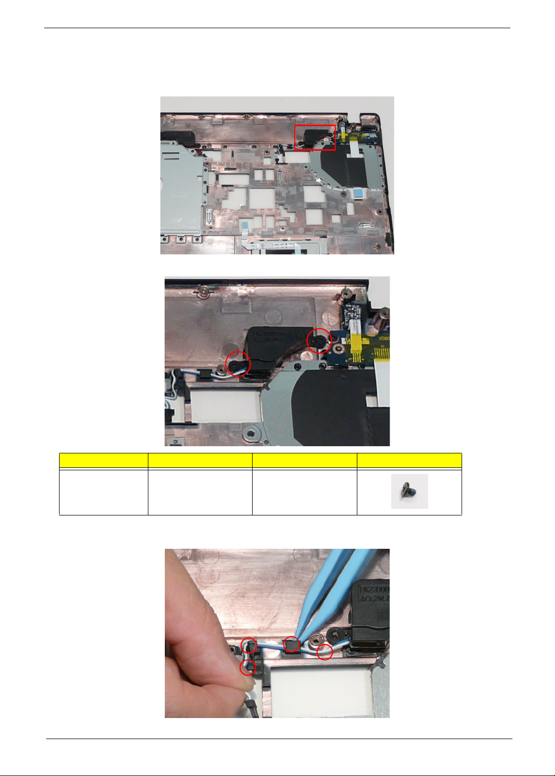
Removing the Right Speaker Module
1. See “Removing the Upper Cover” on page 57.
2. Locate the Right Speaker Module on the Upper Cover as shown.
3. Remove the two (2) securing screws from the Right Speaker Module.
Step Size Quantity Screw Type
Right Speaker
Module
4. Remove the Right Speaker Module cable from the cable channel. Ensure that the cable is free from all cable
clips.
Chapter 3 63
M2*3 2
Page 74
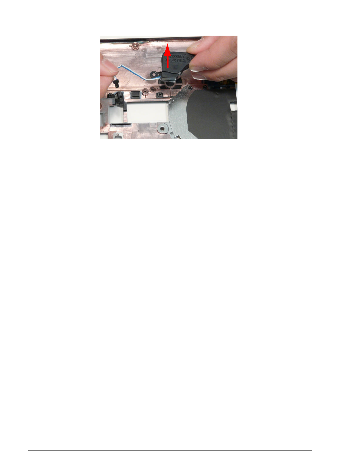
5. Lift the Right Speaker Module clear of the device.
64 Chapter 3
Page 75
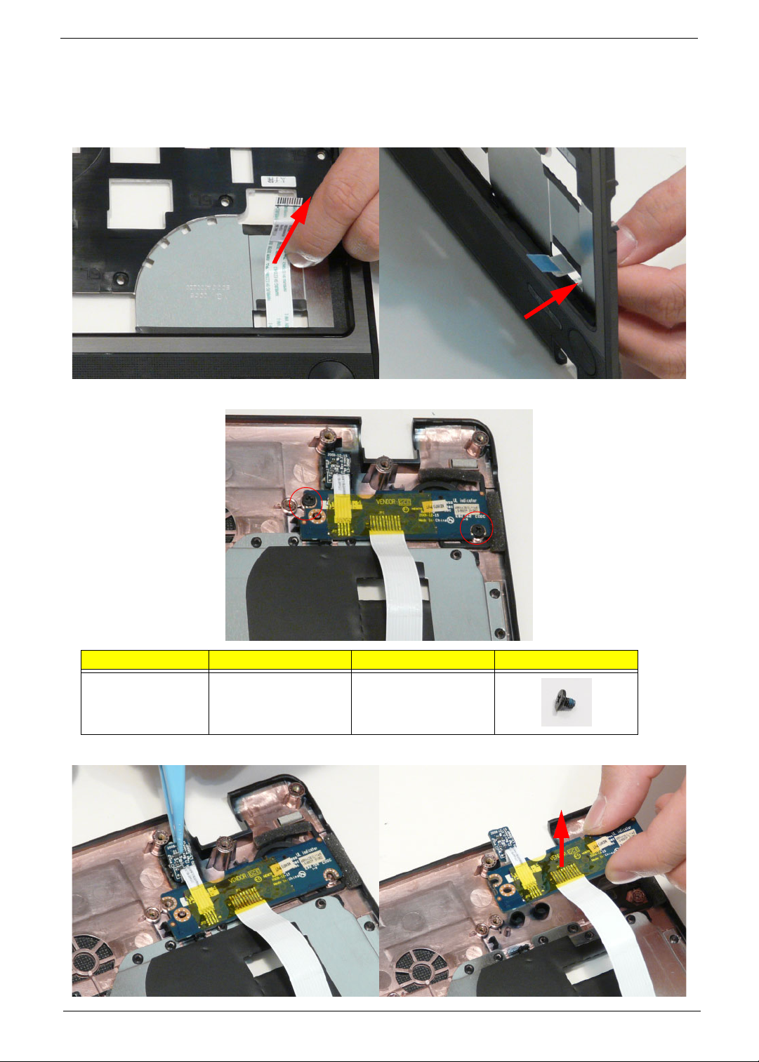
Removing the Power Board
1. See “Removing the Upper Cover” on page 57.
2. Turn the upper cover over and remove the power board cable. Pass the cable through the upper cover as
shown.
3. Remove two (2) screws from the power board.
Step Size Quantity Screw Type
Power board M2*3 2
4. Remove the power board assembly and lift the power board clear of the device.
Chapter 3 65
Page 76
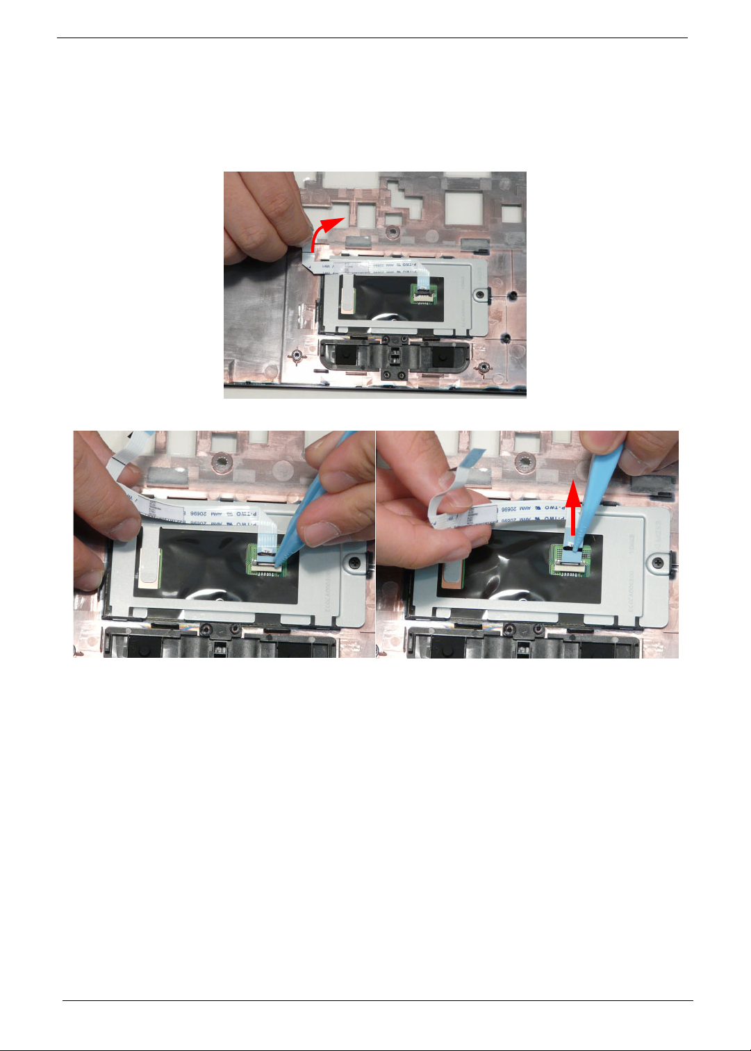
Removing the TouchPad Bracket
IMPORTANT: The TouchPad Board cannot be removed individually. To replace the TouchPad Board, replace the
entire Upper Cover.
1. See “Removing the Upper Cover” on page 57.
2. Lift the FFC to detach the adhesive securing the cable to the Upper Cover.
3. Release the FFC locking latch and disconnect the TouchPad FFC from the cover.
66 Chapter 3
Page 77
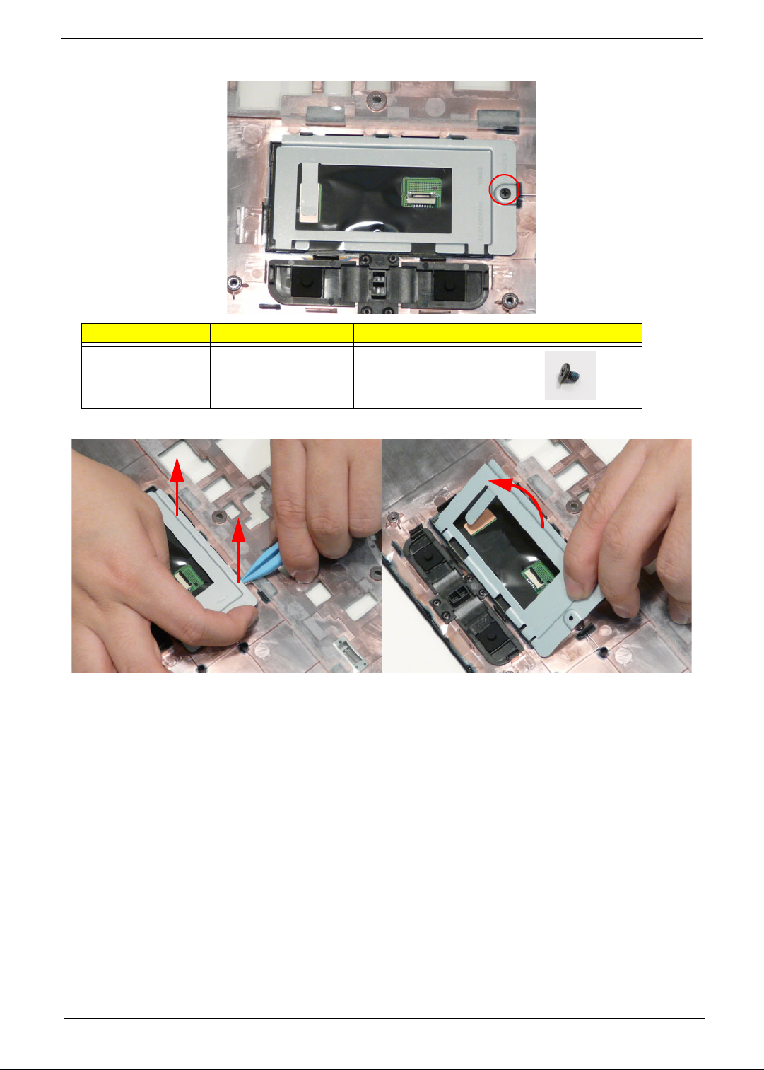
4. Remove the one (1) screw from TouchPad bracket.
Step Size Quantity Screw Type
TouchPad Bracket M2*3 1
5. Pry the Touchpad bracket off the adhesive and remove it as shown.
Chapter 3 67
Page 78
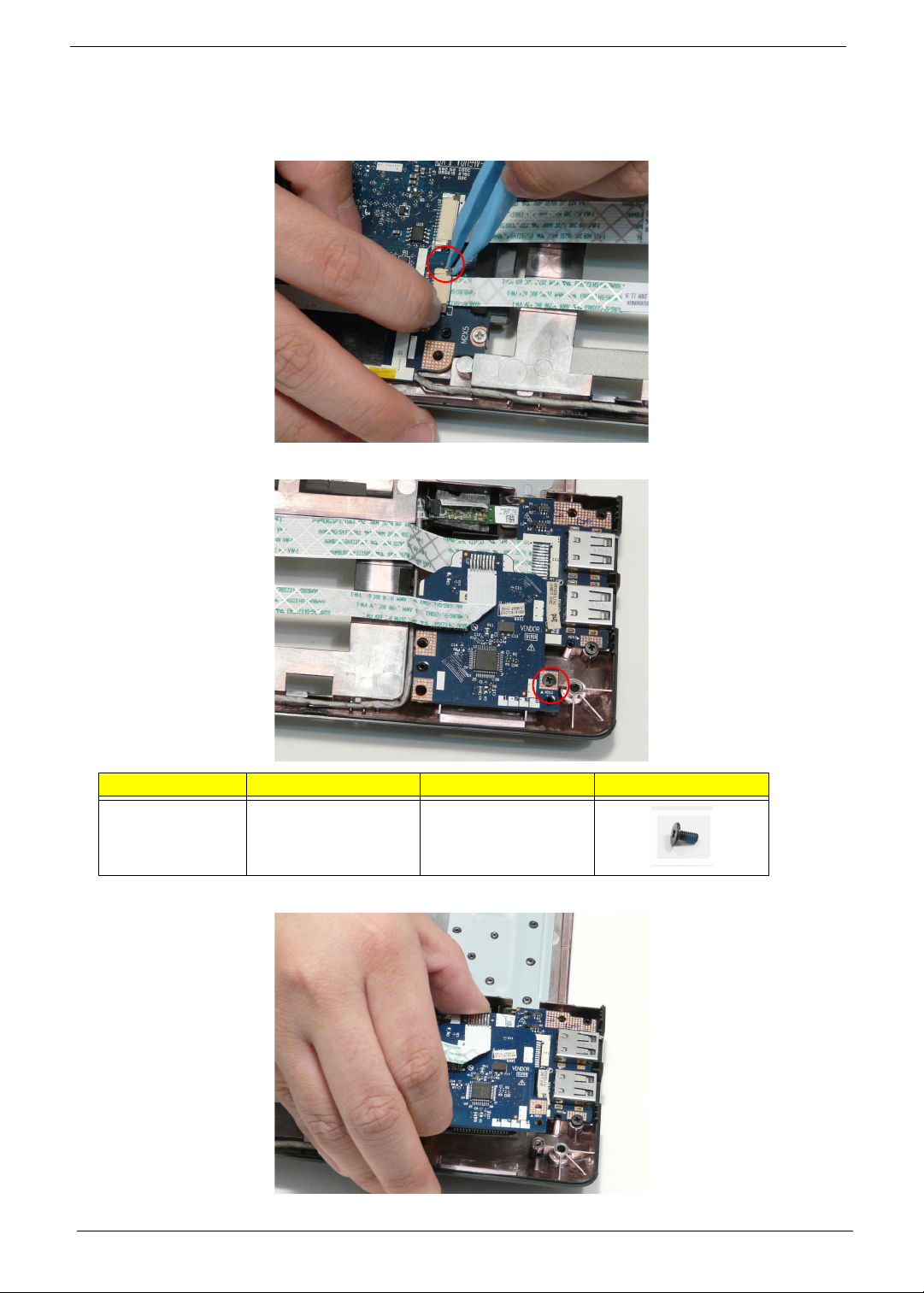
Removing the Card Reader Board
1. See “Removing the Upper Cover” on page 57.
2. Unlock the mainboard to card reader cable connector.
3. Remove one (1) screw from the card reader board.
Step Size Quantity Screw Type
Card Reader M2*3 1
4. Lift the card reader board clear of the device.
68 Chapter 3
Page 79
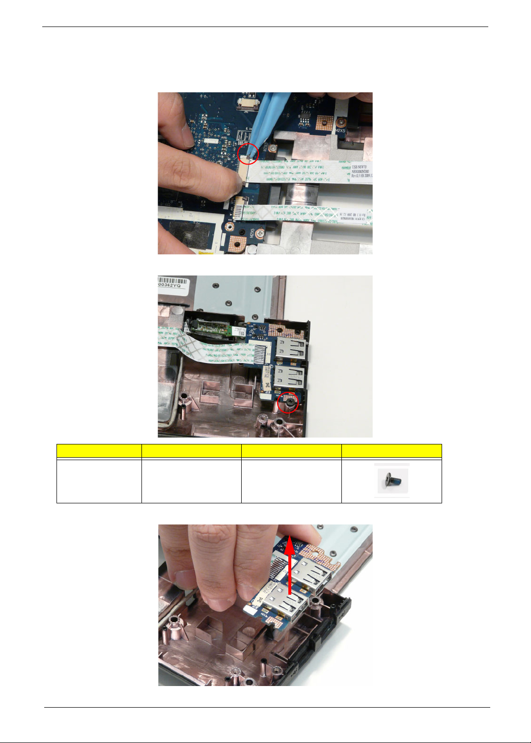
Removing the USB Board
1. See “Removing the Upper Cover” on page 57.
2. Unlock the mainboard to USB cable connector.
3. Remove one (1) screw from the USB board.
Step Size Quantity Screw Type
USB M2*3 1
4. Lift the USB board clear of the device.
Chapter 3 69
Page 80
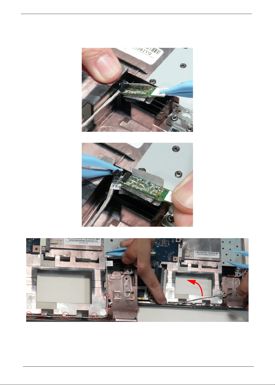
Removing the Bluetooth Board
1. See “Removing the Upper Cover” on page 57.
2. Pry the Bluetooth board from the adhesive.
3. Disconnect the mainboard to Bluetooth cable.
4. Lift the Bluetooth board away from the cable channel as shown.
70 Chapter 3
Page 81
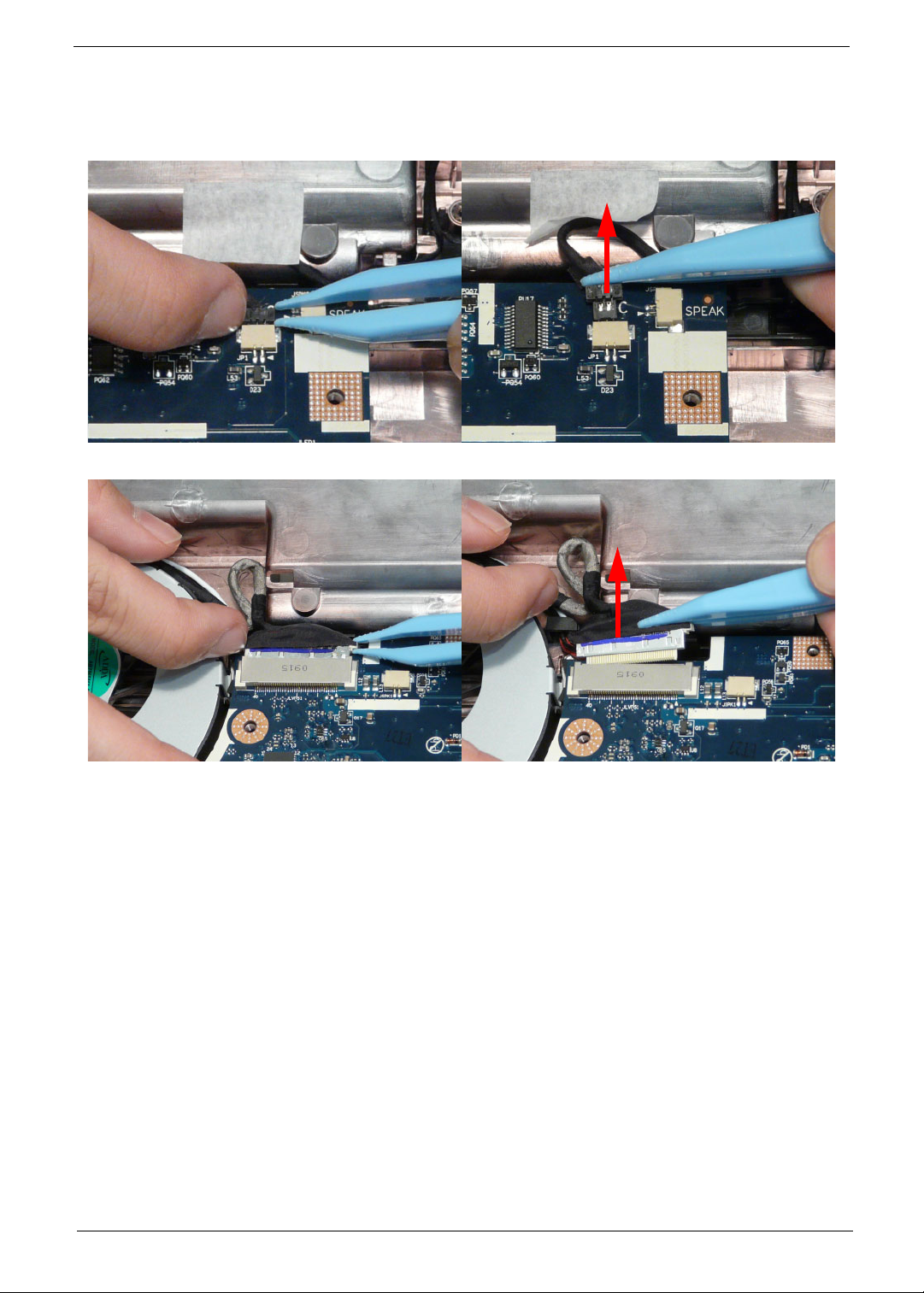
Removing the Mainboard
1. See “Removing the Upper Cover” on page 57.
2. Unlock the microphone cable connector and disconnect the cable.
3. Disconnect the LVDS cable.
Chapter 3 71
Page 82
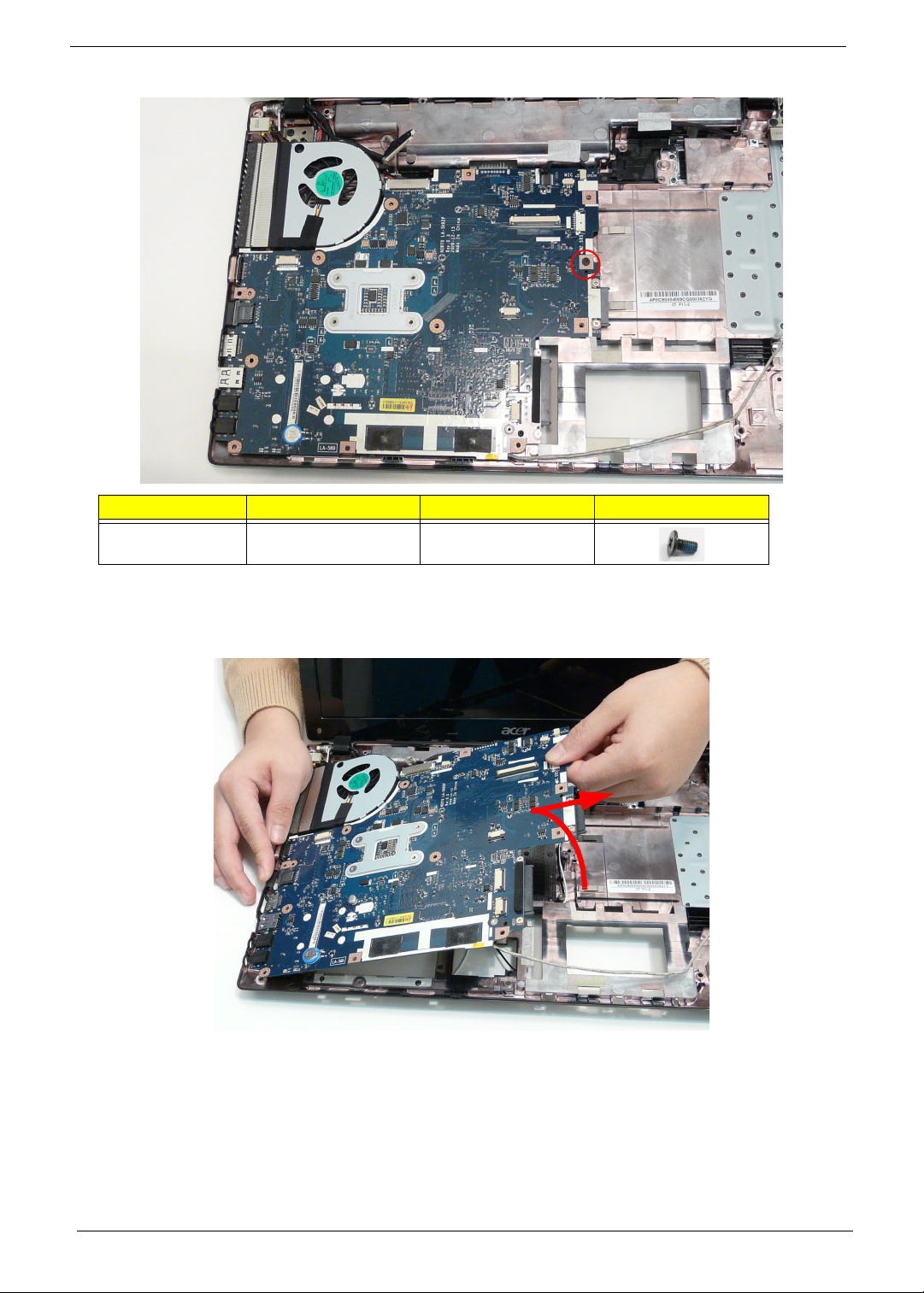
4. Remove the one (1) securing screw from the Mainboard.
Step Size Quantity Screw Type
Mainboard M2.5*5 1
5. Lift the right edge of the mainboard first to free it from the lower case, without removing the mainboard
completely from the chassis.
CAUTION: Do not remove the mainboard completely. The mainboard is still connected to the chassis.
72 Chapter 3
Page 83
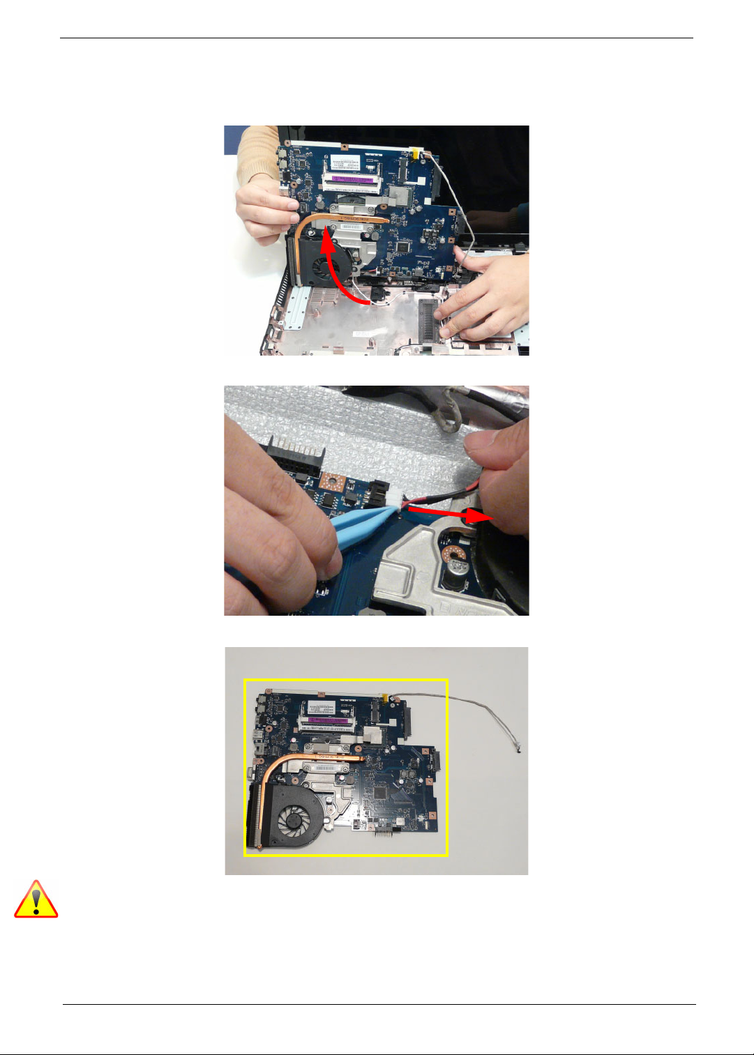
6. Carefully turn the mainboard over and place it on a clean, dust-free surface.
CAUTION: Do not use excessive force when turning the mainboard over as it is still connected to the chassis
by the power cable.
7. Disconnect the power cable.
8. Remove the mainboard from the chassis and turn it over.
NOTE: Circuit boards >10 cm² have been highlighted with a yellow rectangle as shown in the previous
image. Please detach the Circuit board and follow local regulations for disposal.
Chapter 3 73
Page 84
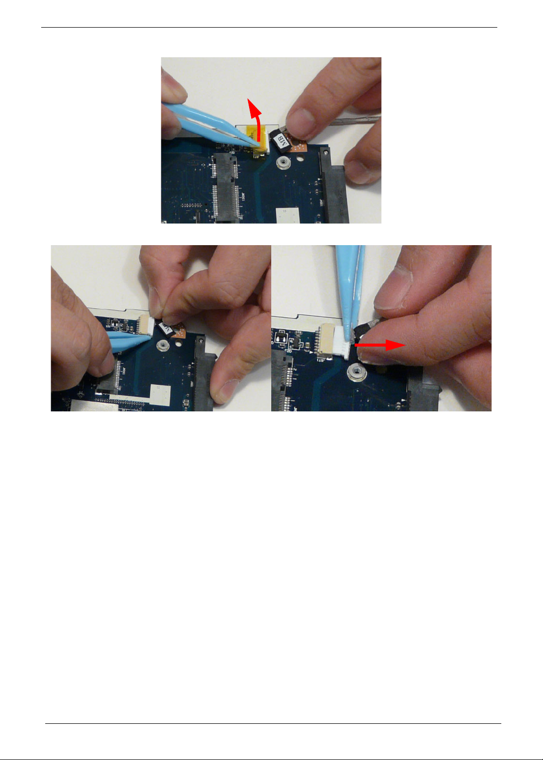
9. Remove the adhesive tape from the bluetooth cable.
10. Unlock the connector and disconnect the bluetooth to mainboard cable.
74 Chapter 3
Page 85
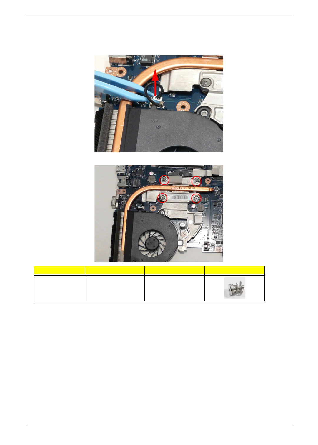
Removing the Thermal Module
1. See “Removing the Upper Cover” on page 57.
2. Disconnect the fan cable.
3. Remove the four (4) securing screws (in reverse numerical order from screw 4 to 1) from the Thermal Module.
2
4
Step Size Quantity Screw Type
Thermal Module M1.98*3 4
1
3
Chapter 3 75
Page 86
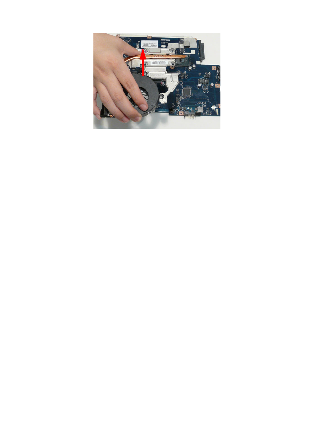
4. Carefully lift the Thermal Module clear of the Mainboard.
76 Chapter 3
Page 87
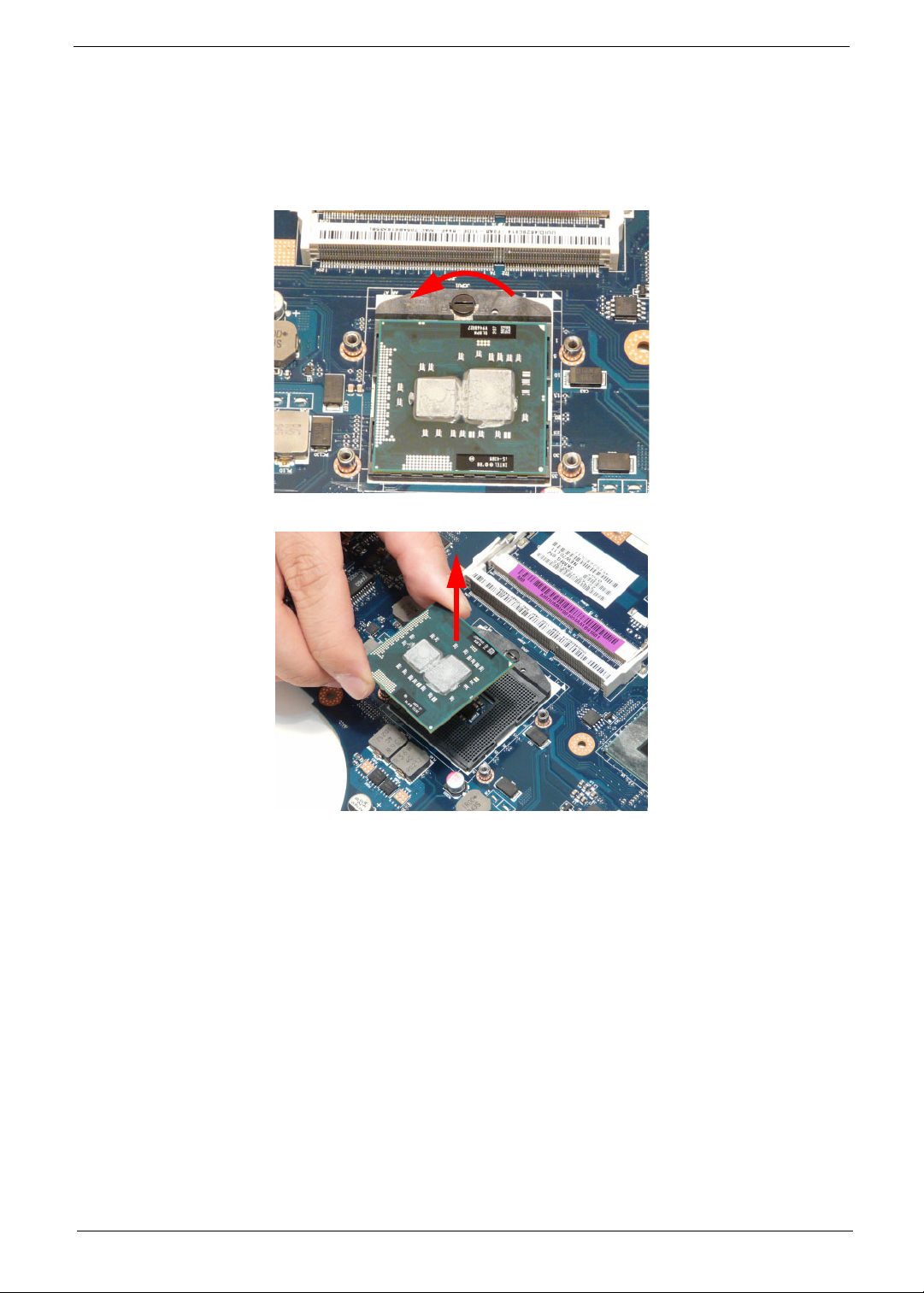
Removing the CPU
IMPORTANT: The pins on the underside of the CPU are very delicate. If they are damaged, the CPU may
malfunction. Place the CPU on a clean, dry surface when it is not installed.
1. See “Removing the Thermal Module” on page 75.
2. Using a flat-bladed screw driver, rotate the CPU locking screw 180° counter-clockwise as shown.
3. Lift the CPU clear of the socket as shown.
Chapter 3 77
Page 88
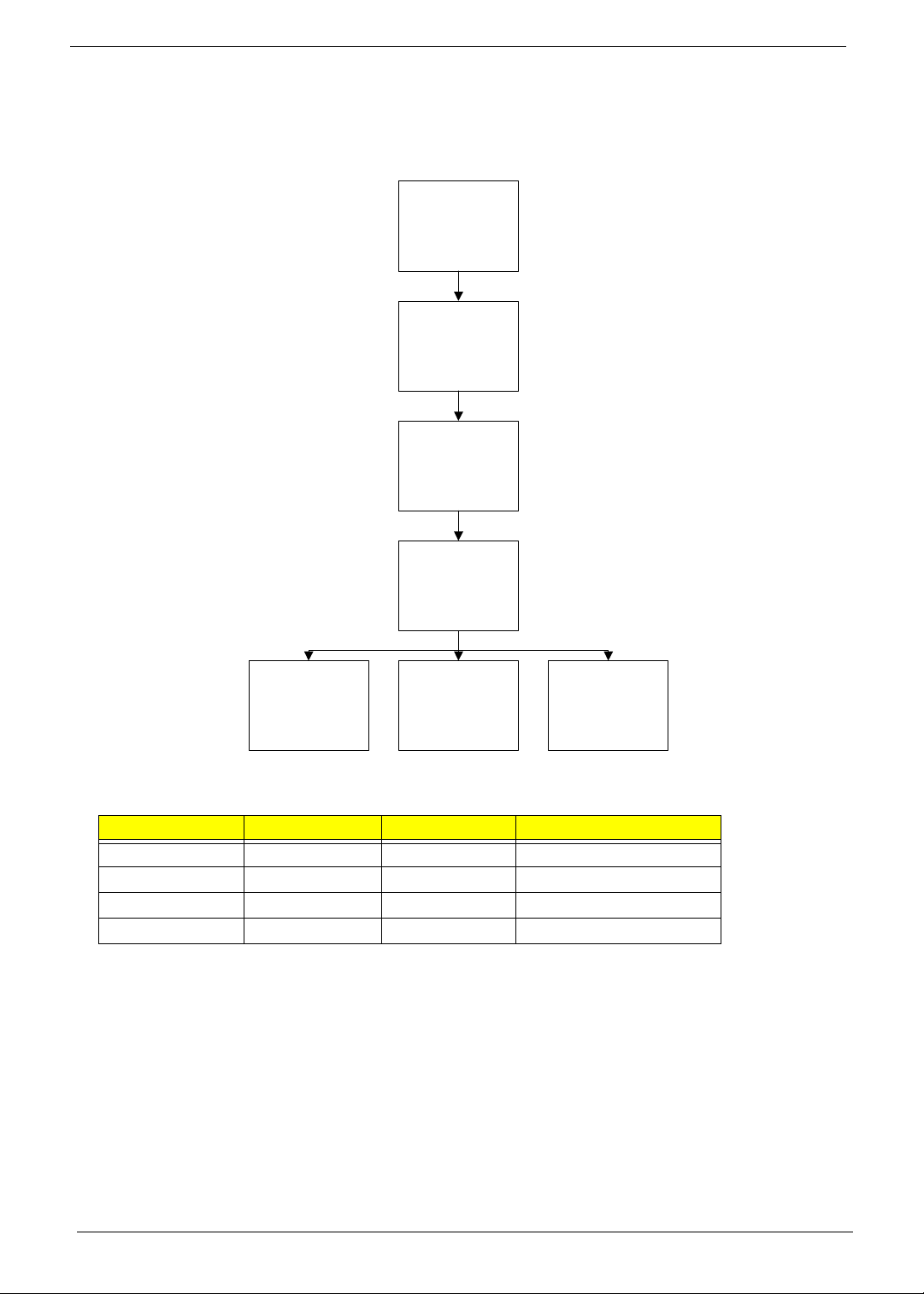
LCD Module Disassembly Process
LCD Module Disassembly Flowchart
Remove LCD
Assembly
Remove
LCD Bezel
Remove
Camera Module
Remove
LCD Panel
Remove
LCD Brackets
and FPC Cable
Remove
Antennas
Remove
Microphone
Cable
Screw List
Step Screw Quantity Part No.
LCD Assy M2.5*8 4 86.PSV02.002
LCD Bezel M2.5*6 2 86.PSV02.003
LCD Panel M2.5*6 2 86.PSV02.003
LCD Brackets M2*3 6 86.PSV02.004
78 Chapter 3
Page 89
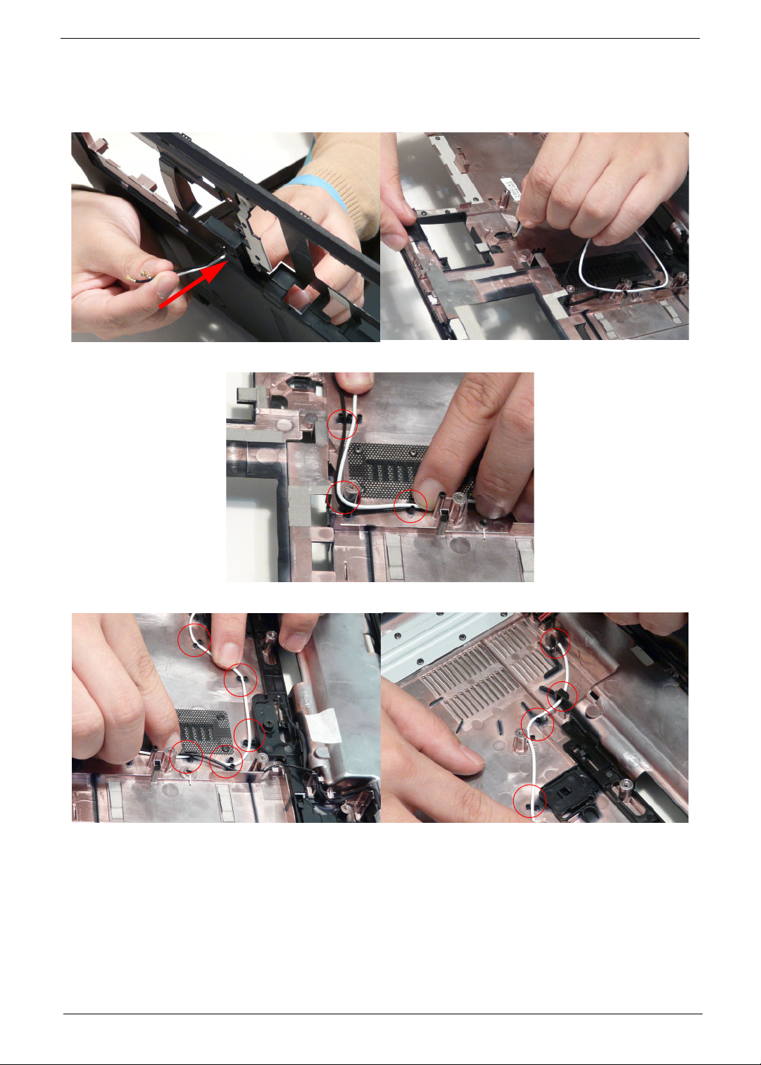
Removing the LCD Assembly
1. See “Removing the Upper Cover” on page 57.
2. Turn the device over and pass the black and white antenna cables through the lower cover.
3. Free the black and white antenna cables from the cable channel as shown.
4. Continue removing the white antenna cable from the cable channel.
Chapter 3 79
Page 90
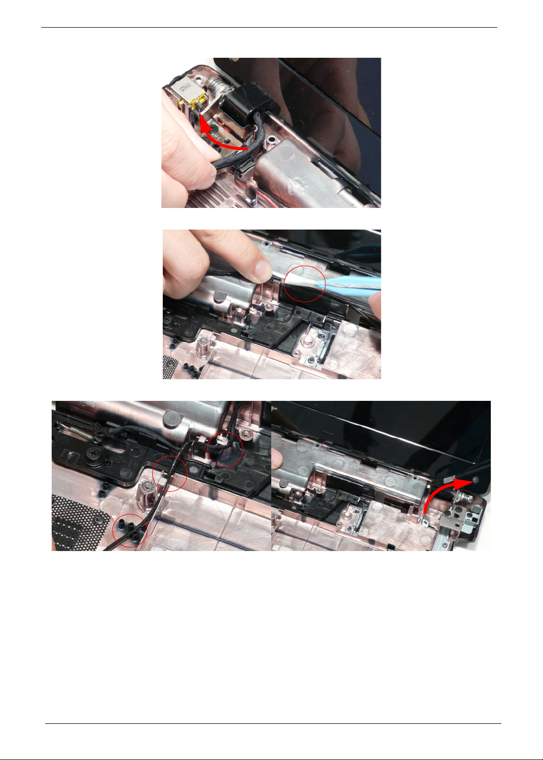
5. Remove the LVDS cable from the cable channel.
6. Remove the adhesive tape from the black antenna cable.
7. Free the cable from the cable channel as shown.
80 Chapter 3
Page 91
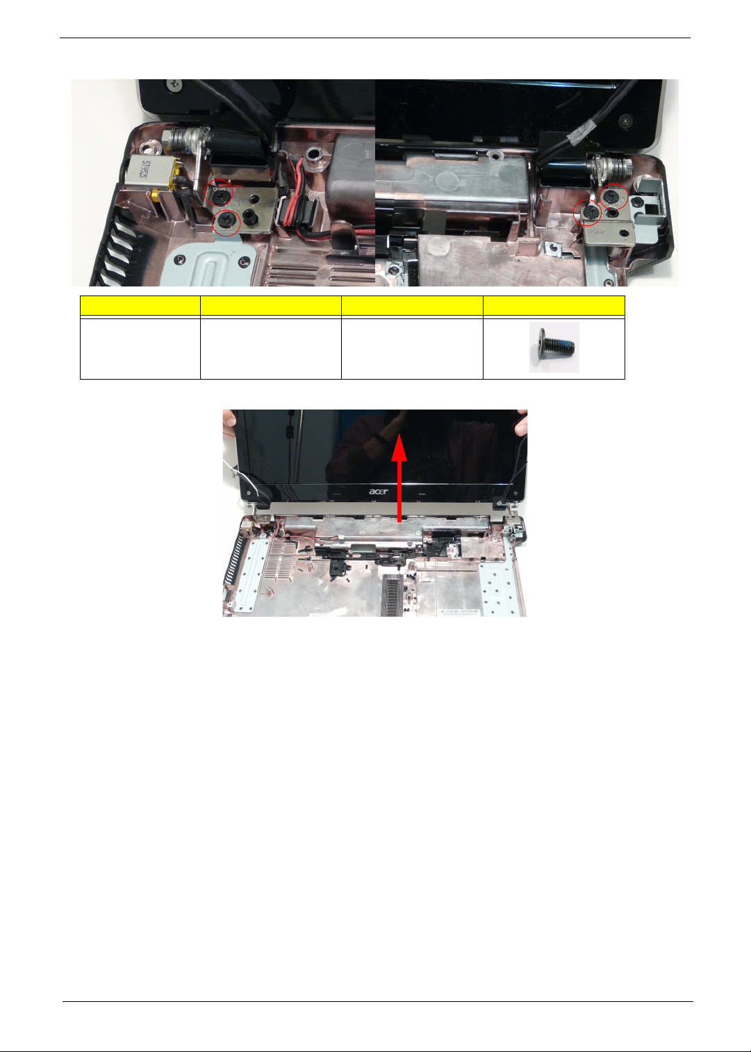
8. Remove four (4) screws from the LCD assembly.
Step Size Quantity Screw Type
LCD assembly M2.5*8 4
9. Remove the LCD assembly from the lower cover.
Chapter 3 81
Page 92

Removing the LCD Bezel
1. See “Removing the LCD Assembly” on page 79.
2. Remove the two bezel screw caps and screws.
Step Size Quantity Screw Type
LCD Bezel M2.5*6 2
3. Starting from the bottom edge of the bezel, pry the bezel upwards and away from the panel. Work along the
right side toward the top of the bezel, prying the covers apart. Continue along the top edge and down the left
side to remove the bezel.
NOTE: If necessary, use a pry to lift up the outside edges of the bezel.
82 Chapter 3
Page 93
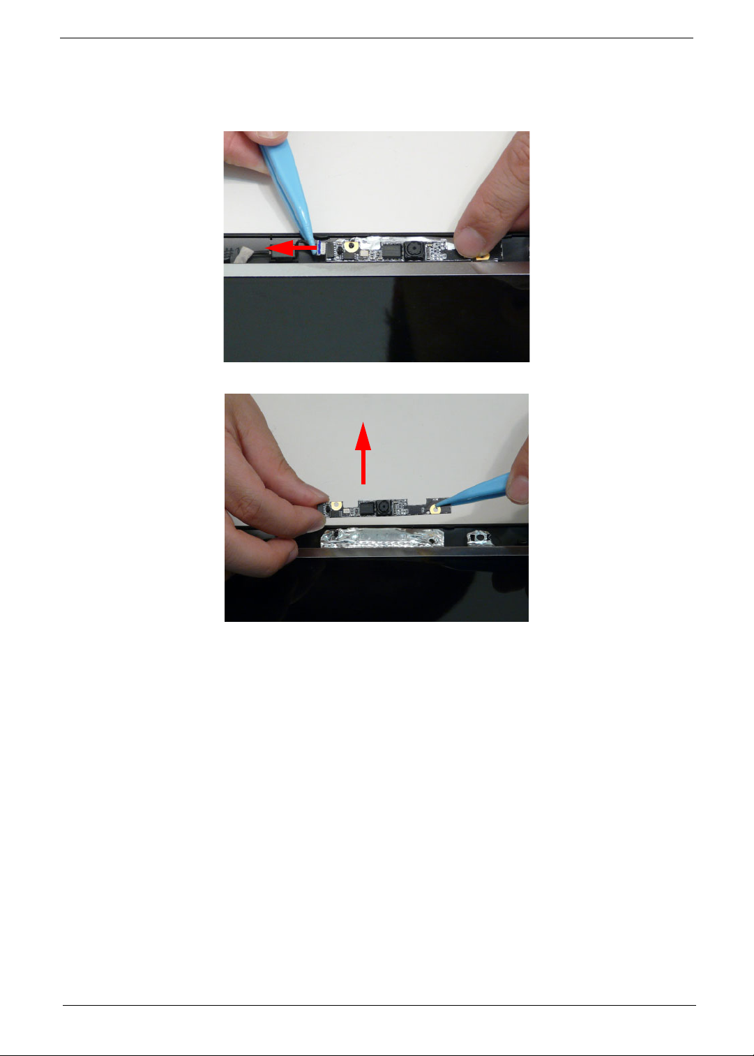
Removing the Camera Module
1. See “Removing the LCD Assembly” on page 79.
2. Locate the Camera Module at the top of the LCD Module and disconnect the camera cable.
3. Remove the Camera from the module.
Chapter 3 83
Page 94
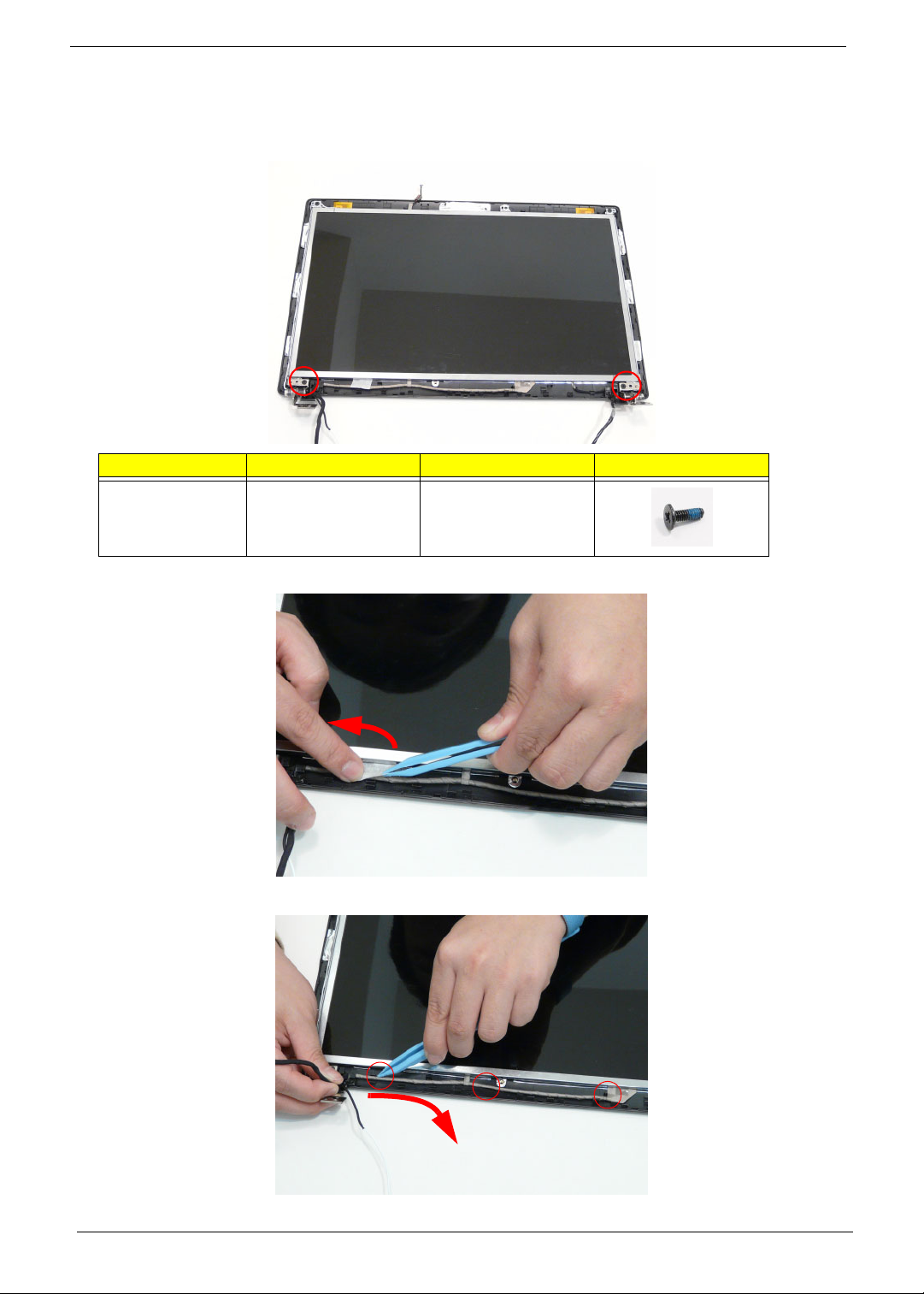
Removing the LCD Panel
1. See “Removing the Camera Module” on page 83.
2. Remove the two (2) securing screws from the LCD Panel.
Step Size Quantity Screw Type
LCD Panel M2.5*6 2
3. Remove the adhesive strip holding the cables in place.
4. Remove the cable from the LCD Module as shown.
84 Chapter 3
Page 95
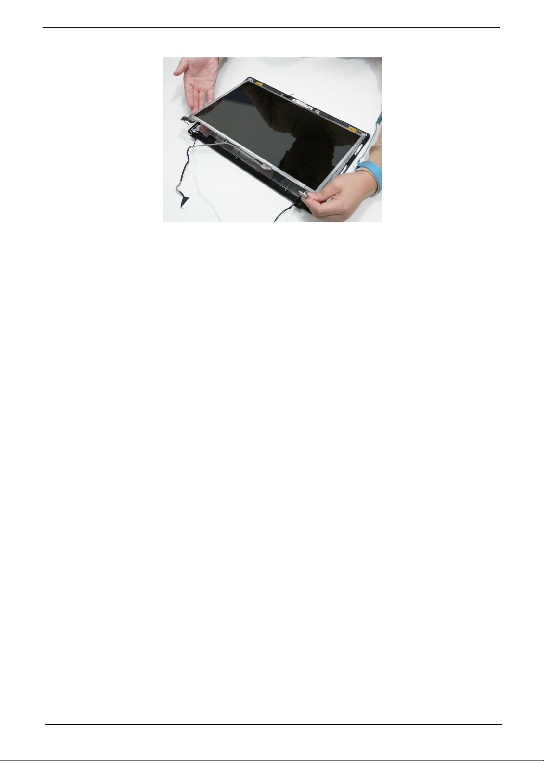
5. Lift the LCD Panel clear of the module.
Chapter 3 85
Page 96
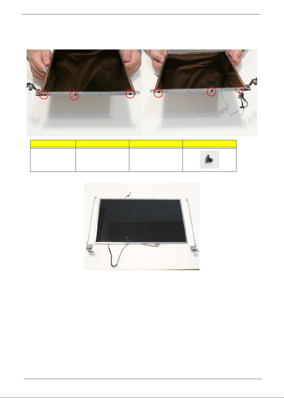
Removing the LCD Brackets and FPC Cable
1. See “Removing the LCD Panel” on page 84.
2. Remove the six (6) securing screws (three on each side) from the LCD Panel brackets.
Step Size Quantity Screw Type
LCD Brackets M2*3 6
3. Remove the LCD brackets by pulling away from the LCD Panel.
86 Chapter 3
Page 97
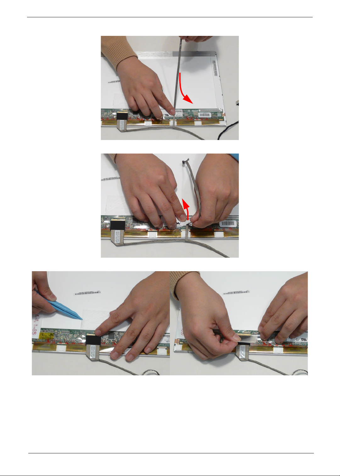
4. Turn the LCD panel over to expose the rear. Pull the cable up as shown.
5. Remove the adhesive tape from the cable.
6. Peel back the mylar securing the LVDS cable.
Chapter 3 87
Page 98
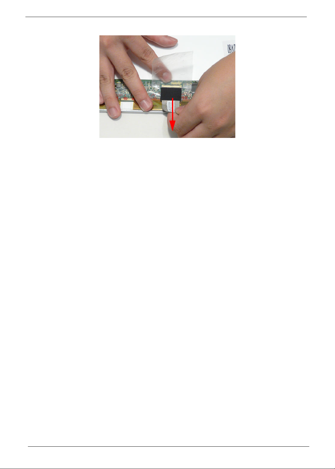
7. Disconnect the LVDS cable from the panel.
88 Chapter 3
Page 99
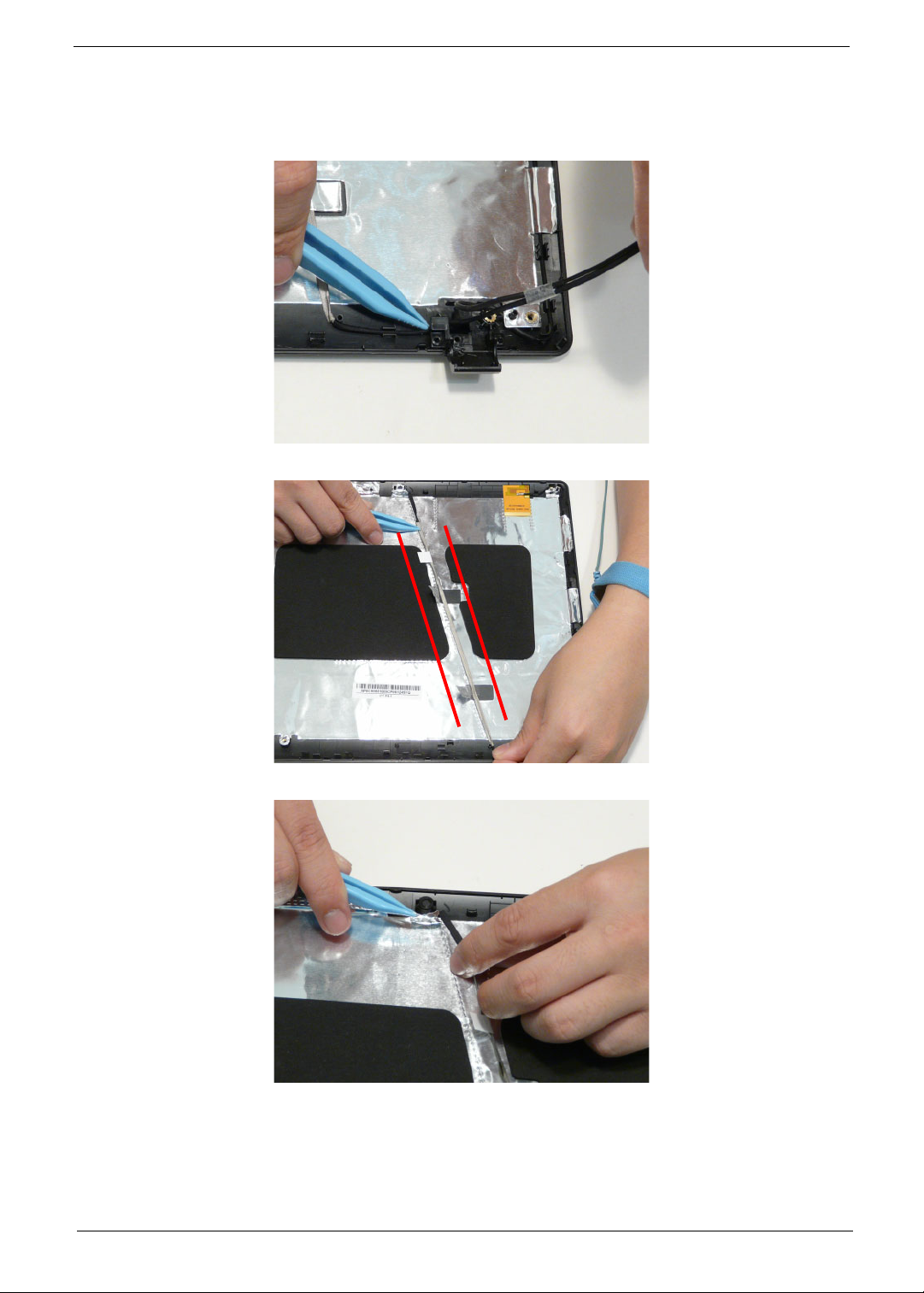
Removing the Microphone Cable
1. See “Removing the LCD Panel” on page 84.
2. Remove the cable bundle from the hinge channel.
3. Peel back the foil tabs and remove the microphone cable from the cable channel.
4. Continue removing the cable from the cable channel.
Chapter 3 89
Page 100
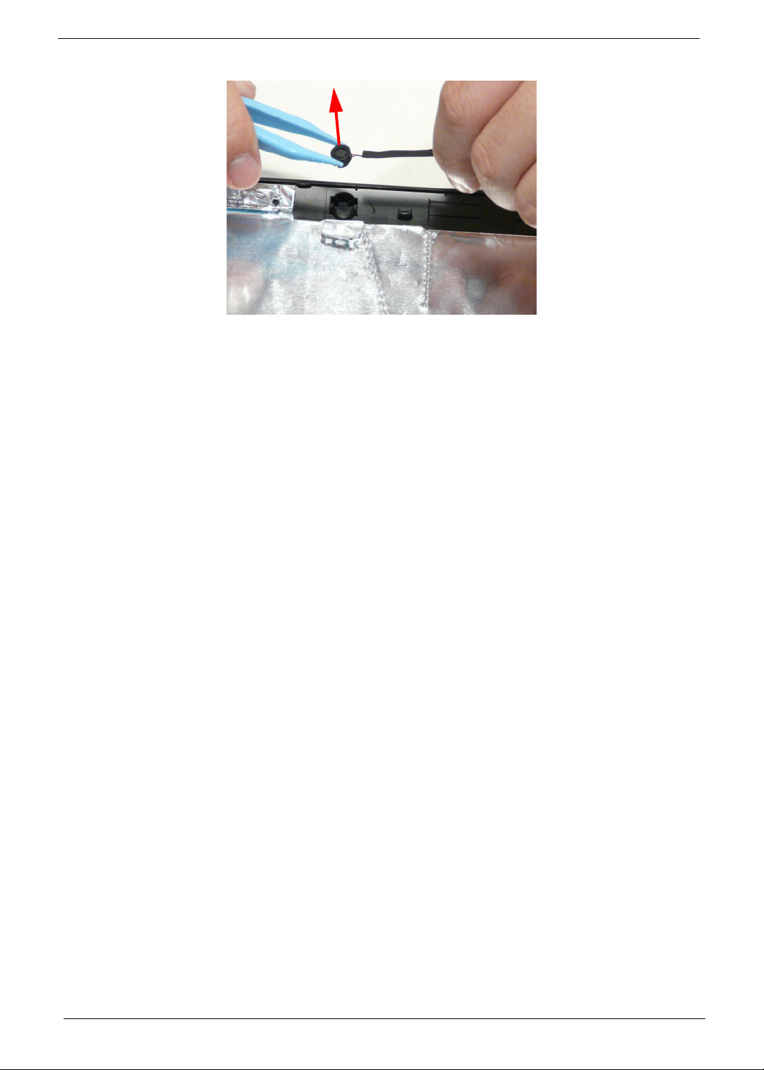
5. Lift the microphone set clear of the panel.
90 Chapter 3
 Loading...