


Aspire 8730/8730Z/8530 Series
Service Guide
Service guide files and updates are available on the ACER/CSD web; for more information, please refer to http://csd.acer.com.tw
PRINTED IN TAIWAN

Revision History
Please refer to the table below for the updates made on Aspire 8730/8730Z/8530 Series service guide.
Date |
Chapter |
Updates |
|
|
|
|
|
|
|
|
|
|
|
|
II

Copyright
Copyright © 2008 by Acer Incorporated. All rights reserved. No part of this publication may be reproduced, transmitted, transcribed, stored in a retrieval system, or translated into any language or computer language, in any form or by any means, electronic, mechanical, magnetic, optical, chemical, manual or otherwise, without the prior written permission of Acer Incorporated.
Disclaimer
The information in this guide is subject to change without notice.
Acer Incorporated makes no representations or warranties, either expressed or implied, with respect to the contents hereof and specifically disclaims any warranties of merchantability or fitness for any particular purpose. Any Acer Incorporated software described in this manual is sold or licensed "as is". Should the programs prove defective following their purchase, the buyer (and not Acer Incorporated, its distributor, or its dealer) assumes the entire cost of all necessary servicing, repair, and any incidental or consequential damages resulting from any defect in the software.
Acer is a registered trademark of Acer Corporation. Intel is a registered trademark of Intel Corporation.
Pentium and Pentium II/III are trademarks of Intel Corporation.
Other brand and product names are trademarks and/or registered trademarks of their respective holders.
III

Conventions
The following conventions are used in this manual:
SCREEN MESSAGES |
Denotes actual messages that appear |
|
on screen. |
|
|
NOTE |
Gives bits and pieces of additional |
|
information related to the current |
|
topic. |
|
|
WARNING |
Alerts you to any damage that might |
|
result from doing or not doing specific |
|
actions. |
|
|
CAUTION |
Gives precautionary measures to |
|
avoid possible hardware or software |
|
problems. |
|
|
IMPORTANT |
Reminds you to do specific actions |
|
relevant to the accomplishment of |
|
procedures. |
|
|
IV

Preface
Before using this information and the product it supports, please read the following general information.
1.This Service Guide provides you with all technical information relating to the BASIC CONFIGURATION decided for Acer's "global" product offering. To better fit local market requirements and enhance product competitiveness, your regional office MAY have decided to extend the functionality of a machine (e.g. add-on card, modem, or extra memory capability). These LOCALIZED FEATURES will NOT be covered in this generic service guide. In such cases, please contact your regional offices or the responsible personnel/channel to provide you with further technical details.
2.Please note WHEN ORDERING FRU PARTS, that you should check the most up-to-date information available on your regional web or channel. If, for whatever reason, a part number change is made, it will not be noted in the printed Service Guide. For ACER-AUTHORIZED SERVICE PROVIDERS, your Acer office may have a DIFFERENT part number code to those given in the FRU list of this printed Service Guide. You MUST use the list provided by your regional Acer office to order FRU parts for repair and service of customer machines.
V

VI

Table of Contents
System Specifications |
1 |
Features. . . . . . . . . . . . . . . . . . . . . . . . . . . . . . . . . . . . . . . . . . . . . . . . . . . . . . . . . . . . 1 System Block Diagram . . . . . . . . . . . . . . . . . . . . . . . . . . . . . . . . . . . . . . . . . . . . . . . . .4 Your Acer Notebook tour . . . . . . . . . . . . . . . . . . . . . . . . . . . . . . . . . . . . . . . . . . . . . . . 6 Right View . . . . . . . . . . . . . . . . . . . . . . . . . . . . . . . . . . . . . . . . . . . . . . . . . . . . . . .9 Indicators . . . . . . . . . . . . . . . . . . . . . . . . . . . . . . . . . . . . . . . . . . . . . . . . . . . . . . 11 Easy-Launch Buttons . . . . . . . . . . . . . . . . . . . . . . . . . . . . . . . . . . . . . . . . . . . . .11 Touchpad basics (with two-click buttons) . . . . . . . . . . . . . . . . . . . . . . . . . . . . . .12 Using the Keyboard . . . . . . . . . . . . . . . . . . . . . . . . . . . . . . . . . . . . . . . . . . . . . . . . . .13 Lock Keys and embedded numeric keypad . . . . . . . . . . . . . . . . . . . . . . . . . . . .13 Windows Keys . . . . . . . . . . . . . . . . . . . . . . . . . . . . . . . . . . . . . . . . . . . . . . . . . .14 Hot Keys . . . . . . . . . . . . . . . . . . . . . . . . . . . . . . . . . . . . . . . . . . . . . . . . . . . . . . 15 Special Key (only for certain models) . . . . . . . . . . . . . . . . . . . . . . . . . . . . . . . . .16
Acer Empowering Technology . . . . . . . . . . . . . . . . . . . . . . . . . . . . . . . . . . . . . . . . . .17 Launching Acer Empowering Technology . . . . . . . . . . . . . . . . . . . . . . . . . . . . .17 Empowering Technology password . . . . . . . . . . . . . . . . . . . . . . . . . . . . . . . . . .18 Acer eAudio Management (only for certain models) . . . . . . . . . . . . . . . . . . . . .19 Acer ePower Management . . . . . . . . . . . . . . . . . . . . . . . . . . . . . . . . . . . . . . . . 20 Acer eDataSecurity Management (only for certain models) . . . . . . . . . . . . . . . 21 Acer eRecovery Management . . . . . . . . . . . . . . . . . . . . . . . . . . . . . . . . . . . . . .22 Acer eSettings Management . . . . . . . . . . . . . . . . . . . . . . . . . . . . . . . . . . . . . . . 24 Windows Mobility Center . . . . . . . . . . . . . . . . . . . . . . . . . . . . . . . . . . . . . . . . . .25
Using the System Utilities . . . . . . . . . . . . . . . . . . . . . . . . . . . . . . . . . . . . . . . . . . . . . .26 Acer GridVista (dual-display compatible) . . . . . . . . . . . . . . . . . . . . . . . . . . . . . .26 Hardware Specifications and Configurations. . . . . . . . . . . . . . . . . . . . . . . . . . . . . . . 28
System Utilities |
37 |
BIOS Setup Utility . . . . . . . . . . . . . . . . . . . . . . . . . . . . . . . . . . . . . . . . . . . . . . . . . . . .37
Navigating the BIOS Utility. . . . . . . . . . . . . . . . . . . . . . . . . . . . . . . . . . . . . . . . . 38
Information . . . . . . . . . . . . . . . . . . . . . . . . . . . . . . . . . . . . . . . . . . . . . . . . . . . . . 39
Main . . . . . . . . . . . . . . . . . . . . . . . . . . . . . . . . . . . . . . . . . . . . . . . . . . . . . . . . . . 40
Security . . . . . . . . . . . . . . . . . . . . . . . . . . . . . . . . . . . . . . . . . . . . . . . . . . . . . . . 42
Boot . . . . . . . . . . . . . . . . . . . . . . . . . . . . . . . . . . . . . . . . . . . . . . . . . . . . . . . . . . .46
Exit . . . . . . . . . . . . . . . . . . . . . . . . . . . . . . . . . . . . . . . . . . . . . . . . . . . . . . . . . . .47
BIOS Flash Utility . . . . . . . . . . . . . . . . . . . . . . . . . . . . . . . . . . . . . . . . . . . . . . . . . . . .48
Remove HDD Password . . . . . . . . . . . . . . . . . . . . . . . . . . . . . . . . . . . . . . . . . . . . . . .49
Machine Disassembly and Replacement |
51 |
Disassembly Requirements . . . . . . . . . . . . . . . . . . . . . . . . . . . . . . . . . . . . . . . . . . . |
.51 |
General Information . . . . . . . . . . . . . . . . . . . . . . . . . . . . . . . . . . . . . . . . . . . . . . . . . . |
52 |
Pre-disassembly Instructions . . . . . . . . . . . . . . . . . . . . . . . . . . . . . . . . . . . . . . . |
52 |
Disassembly Process. . . . . . . . . . . . . . . . . . . . . . . . . . . . . . . . . . . . . . . . . . . . . |
52 |
External Module Disassembly Process . . . . . . . . . . . . . . . . . . . . . . . . . . . . . . . . . . . |
53 |
External Modules Disassembly Flowchart . . . . . . . . . . . . . . . . . . . . . . . . . . . . . |
53 |
Removing the Battery Pack . . . . . . . . . . . . . . . . . . . . . . . . . . . . . . . . . . . . . . . . |
54 |
Removing the SD dummy card . . . . . . . . . . . . . . . . . . . . . . . . . . . . . . . . . . . . . |
55 |
Removing the ExpressCard dummy card . . . . . . . . . . . . . . . . . . . . . . . . . . . . . |
56 |
Removing the Lower Cover . . . . . . . . . . . . . . . . . . . . . . . . . . . . . . . . . . . . . . . . |
56 |
Removing the DIMM . . . . . . . . . . . . . . . . . . . . . . . . . . . . . . . . . . . . . . . . . . . . . |
58 |
Removing the TV Tuner Board Modules . . . . . . . . . . . . . . . . . . . . . . . . . . . . . . . |
58 |
Removing the WLAN Board Modules . . . . . . . . . . . . . . . . . . . . . . . . . . . . . . . . |
61 |
Removing the Hard Disk Drive Module 1 . . . . . . . . . . . . . . . . . . . . . . . . . . . . . . |
64 |
Removing the Hard Disk Drive Module 2 . . . . . . . . . . . . . . . . . . . . . . . . . . . . . . |
66 |
Removing the Optical Drive Module . . . . . . . . . . . . . . . . . . . . . . . . . . . . . . . . . . |
69 |
VII

Table of Contents |
|
Main Unit Disassembly Process . . . . . . . . . . . . . . . . . . . . . . . . . . . . . . . . . . . . . . . |
. .72 |
Main Unit Disassembly Flowchart . . . . . . . . . . . . . . . . . . . . . . . . . . . . . . . . . . |
. .72 |
Removing the Middle Cover. . . . . . . . . . . . . . . . . . . . . . . . . . . . . . . . . . . . . . . |
. 73 |
Removing the Keyboard . . . . . . . . . . . . . . . . . . . . . . . . . . . . . . . . . . . . . . . . . |
. .74 |
Removing the Power Board . . . . . . . . . . . . . . . . . . . . . . . . . . . . . . . . . . . . . . |
. .75 |
Removing the Heatsink Module . . . . . . . . . . . . . . . . . . . . . . . . . . . . . . . . . . . |
. .78 |
Removing the CPU . . . . . . . . . . . . . . . . . . . . . . . . . . . . . . . . . . . . . . . . . . . . . |
. 80 |
Removing the Discrete Board Module (For Discrete Models Only) . . . . . . . . . |
. 82 |
Removing the LCD Module . . . . . . . . . . . . . . . . . . . . . . . . . . . . . . . . . . . . . . . |
. .84 |
Separating the Upper Case from the Lower Case . . . . . . . . . . . . . . . . . . . . . . |
. 87 |
Removing the E-Key Board . . . . . . . . . . . . . . . . . . . . . . . . . . . . . . . . . . . . . . . |
. 93 |
Removing the Fingerprint Board . . . . . . . . . . . . . . . . . . . . . . . . . . . . . . . . . . . |
. .95 |
Removing the Touchpad Board . . . . . . . . . . . . . . . . . . . . . . . . . . . . . . . . . . . . |
. 97 |
Removing the Modem Board . . . . . . . . . . . . . . . . . . . . . . . . . . . . . . . . . . . . . |
.100 |
Removing the Main Board . . . . . . . . . . . . . . . . . . . . . . . . . . . . . . . . . . . . . . . |
.101 |
Removing the Speaker Module . . . . . . . . . . . . . . . . . . . . . . . . . . . . . . . . . . . . |
.103 |
Removing the Subwoofer. . . . . . . . . . . . . . . . . . . . . . . . . . . . . . . . . . . . . . . . . |
105 |
Removing the USB Board Module . . . . . . . . . . . . . . . . . . . . . . . . . . . . . . . . . |
.106 |
LCD Module Disassembly Process . . . . . . . . . . . . . . . . . . . . . . . . . . . . . . . . . . . . |
.109 |
LCD Module Disassembly Flowchart . . . . . . . . . . . . . . . . . . . . . . . . . . . . . . . |
.109 |
Removing the LCD Bezel . . . . . . . . . . . . . . . . . . . . . . . . . . . . . . . . . . . . . . . . |
.110 |
Removing the LCD panel with the Brackets . . . . . . . . . . . . . . . . . . . . . . . . . . |
111 |
Removing the Inverter Board and FPC Cable . . . . . . . . . . . . . . . . . . . . . . . . |
.113 |
Removing the LCD Brackets . . . . . . . . . . . . . . . . . . . . . . . . . . . . . . . . . . . . . . |
116 |
Removing the Antennas. . . . . . . . . . . . . . . . . . . . . . . . . . . . . . . . . . . . . . . . . . |
116 |
Removing the Web Camera . . . . . . . . . . . . . . . . . . . . . . . . . . . . . . . . . . . . . . |
.118 |
Troubleshooting |
119 |
System Check Procedures . . . . . . . . . . . . . . . . . . . . . . . . . . . . . . . . . . . . . . . . . . . |
.120 |
External Diskette Drive Check . . . . . . . . . . . . . . . . . . . . . . . . . . . . . . . . . . . . |
.120 |
External CD-ROM Drive Check . . . . . . . . . . . . . . . . . . . . . . . . . . . . . . . . . . . |
.120 |
Keyboard or Auxiliary Input Device Check . . . . . . . . . . . . . . . . . . . . . . . . . . . |
.120 |
Memory Check. . . . . . . . . . . . . . . . . . . . . . . . . . . . . . . . . . . . . . . . . . . . . . . . . |
121 |
Power System Check . . . . . . . . . . . . . . . . . . . . . . . . . . . . . . . . . . . . . . . . . . . |
.121 |
Touchpad Check . . . . . . . . . . . . . . . . . . . . . . . . . . . . . . . . . . . . . . . . . . . . . . . |
.123 |
Power-On Self-Test (POST) Error Message . . . . . . . . . . . . . . . . . . . . . . . . . . . . . |
.124 |
Index of Error Messages . . . . . . . . . . . . . . . . . . . . . . . . . . . . . . . . . . . . . . . . . . . . . |
.125 |
Phoenix BIOS Beep Codes . . . . . . . . . . . . . . . . . . . . . . . . . . . . . . . . . . . . . . . . . . |
.128 |
Index of Symptom-to-FRU Error Message . . . . . . . . . . . . . . . . . . . . . . . . . . . . . . . |
133 |
Intermittent Problems . . . . . . . . . . . . . . . . . . . . . . . . . . . . . . . . . . . . . . . . . . . . . . . |
.137 |
Undetermined Problems . . . . . . . . . . . . . . . . . . . . . . . . . . . . . . . . . . . . . . . . . . . . . |
.138 |
Jumper and Connector Locations |
139 |
Motherboard . . . . . . . . . . . . . . . . . . . . . . . . . . . . . . . . . . . . . . . . . . . . . . . . . . . . . . .139 Clearing Password Check and BIOS Recovery . . . . . . . . . . . . . . . . . . . . . . . . . . . .141 Clearing Password Check . . . . . . . . . . . . . . . . . . . . . . . . . . . . . . . . . . . . . . . . .141 BIOS Recovery by Crisis Disk . . . . . . . . . . . . . . . . . . . . . . . . . . . . . . . . . . . . . 143
FRU (Field Replaceable Unit) List |
145 |
Aspire 8730/8730Z/8530 Series Exploded Diagram . . . . . . . . . . . . . . . . . . . . . . . . |
.146 |
Model Definition and Configuration |
154 |
Aspire 8730/8730Z/8530 Series . . . . . . . . . . . . . . . . . . . . . . . . . . . . . . . . . . . . . . . .154
VIII

|
Table of Contents |
Test Compatible Components |
179 |
Microsoft® Windows® Vista Environment Test . . . |
. . . . . . . . . . . . . . . . . . . . . . . . .180 |
Online Support Information |
183 |
Index |
185 |
IX

Table of Contents
X
Chapter 1
System Specifications
Features
Below is a brief summary of the computer’s many feature:
Platform
For Aspire 8730/8730Z Series
Intel® Centrino® 2 processor technology, featuring:
•Intel® Core™2 Duo processor
•Intel® Pentium® dual-core processor*
•Mobile Intel® PM45/GM45 Express Chipset*
•Intel® Wireless WiFi Link 5100/5300*
•Acer InviLink™ Nplify™ 802.11b/g/Draft-N*
•Acer InviLink™ 802.11b/g*
For Aspire 8530 Series
AMD Better By Design program, featuring:
•AMD Turion™ X2 Ultra dual-core mobile processor*
•AMD Turion™ X2 dual-core mobile processor*
•AMD Athlon™ X2 dual-core mobile processor*
•AMD M780G Chipset*
•Acer InviLink™ Nplify™ 802.11b/g/Draft-N*
•Acer InviLink™ 802.11b/g*
System Memory
•Dual-channel SDRAM support
•Up to 2 GB of DDR2 667 MHz memory, upgradeable to 4 GB using two soDIMM modules*
Display and graphics
•16:9 aspect ratio
•18.4" Full HD 1920 x 1080*
•18.4" HD+ 1680 x 945*
•Digital TV-tuner supporting DVB-T* For Aspire 8730/8730Z Series:
•Mobile Intel® GM45 Express Chipset*
•NVIDIA® GeForce® 9300M GS*
•NVIDIA® GeForce® 9600M GT*
For Aspire 8530 Series
•ATI Radeon™ HD 3200 Graphics*
•ATI Mobility Radeon™ HD 3470 Hybrid x 2*
•ATI Mobility Radeon™ HD 3650*
Chapter 1 |
1 |

Storage subsystem
•2.5" hard disk drive
•Optical drive options:
•Blu-ray Disc™/DVD-Super Multi double-layer drive*
•DVD-Super Multi double-layer drive*
•6-in-1 card reader
Special keys and controls
•105/106-key keyboard
•Touchpad pointing device
Audio
•Dolby®-optimized surround sound system with two built-in stereo speakers and one subwoofer* supporting low-frequency effects
•True5.1-channel surround sound output
•High-definition audio support
•S/PDIF (Sony/Philips Digital Interface) support for digital speakers
•MS-Sound compatible
•Built-in microphone
Communication
•Acer Video Conference, featuring:
•Integrated Acer Crystal Eye webcam*
•Optional Acer Xpress VoIP phone*
•WLAN:
•Intel® Wireless WiFi Link 5100/5300*
•Acer InviLink™ Nplify™ 802.11b/g/Draft-N*
•Acer InviLink™ 802.11b/g*
•WPAN: Bluetooth® 2.0+Enhanced Data Rate (EDR)*
•LAN: Gigabit Ethernet; Wake-on-LAN ready
•Modem: 56K ITU V.92; Wake-on-Ring ready
I/O Ports
•ExpressCard™/54 slot
•Acer Bio-Protection fingerprint reader*
•6-in-1 card reader (SD/MMC/MMCplus™/MS/MS PRO/xD)
•USB 2.0 port
•HDMI™ port with HDCP support
•External display (VGA) port
•Consumer infrared (CIR) port
•RF-in jack*
•Headphones/speaker/line-out jack with S/PDIF support
•Microphone-in jack
•Line-in jack
•Ethernet (RJ-45) port
2 |
Chapter 1 |

•Modem (RJ-11) port
•DC-in jack for AC adapter
Environment
•Temperature:
•Operating: 5 °C to 35 °C
•Non-operating: -20 °C to 65 °C
•Humidity (non-condensing):
•Operating: 20% to 80%
•Non-operating: 20% to 80% NOTE: "*" "Only for certain models"
NOTE: The specifications listed above are for reference only. The exact configuration of your PC depends on the model purchased.
Chapter 1 |
3 |
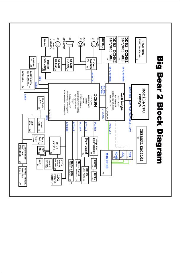
System Block Diagram
For Aspire 8730/8730Z Series:
4 |
Chapter 1 |

For Aspire 8530 Series:
Chapter 1 |
5 |
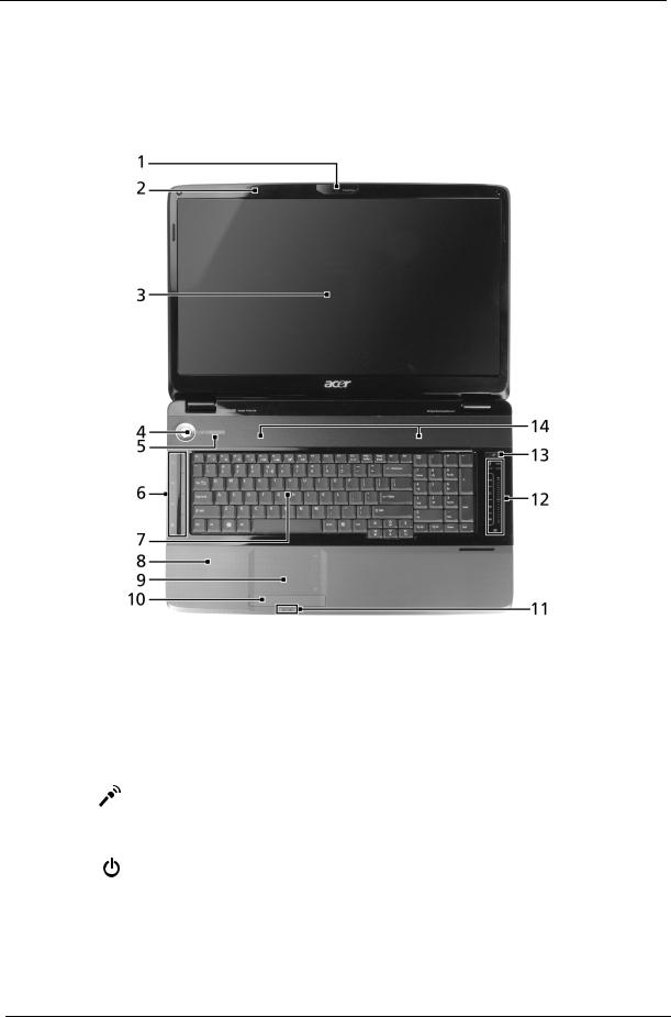
Your Acer Notebook tour
After knowing your computer features, let us show you around your new computer.
Front View
|
Icon |
Item |
Description |
|
|
|
|
1 |
|
Acer Crystal Eye |
Web camera for video communication. |
|
|
webcam |
|
|
|
|
|
2 |
|
Microphone |
Internal microphone for sound recording. |
|
|
|
|
3 |
|
Display screen |
Also called Liquid-Crystal Display (LCD), displays computer |
|
|
|
output (Configuration may vary by models). |
|
|
|
|
4 |
|
Power button |
Turns the computer on and off. |
|
|
|
|
5/11 |
|
Status indicators |
Light-Emitting Diodes (LEDs) that light up to show the status of |
|
|
|
the computer's functions and components. |
|
|
|
|
6 |
|
Easy-launch |
Buttons for launching frequently used programs. |
|
|
buttons |
|
|
|
|
|
7 |
|
Keyboard |
For entering data into your computer. |
|
|
|
|
6 |
Chapter 1 |
|
Icon |
Item |
Description |
|
|
|
|
8 |
|
Palmrest |
Comfortable support area for your hands when you use the |
|
|
|
computer. |
|
|
|
|
9 |
|
Touchpad |
Touch-sensitive pointing device which functions like a computer |
|
|
|
mouse. |
|
|
|
|
10 |
|
Click buttons (left, |
The left and right buttons function like the left and right mouse |
|
|
center* and right) |
buttons. *The center button serves as Acer Bio-Protection |
|
|
|
fingerprint reader supporting Acer FingerNav 4-way control |
|
|
|
function |
|
|
|
(only for certain models). |
|
|
|
|
12.1 |
VOL+/ |
Volume Up/Volume |
Increase system volume/decrease system volume. |
|
VOL- |
Down |
|
|
|
|
|
12.2 |
|
Acer MediaTouch |
For use with Acer Arcade and other media playing programs. |
|
|
keys |
|
|
|
|
|
13 |
|
Empowering key |
Launch Acer Empowering Technology |
|
|
|
|
14 |
|
Speakers |
Left and right speakers deliver stereo audio output. |
|
|
|
|
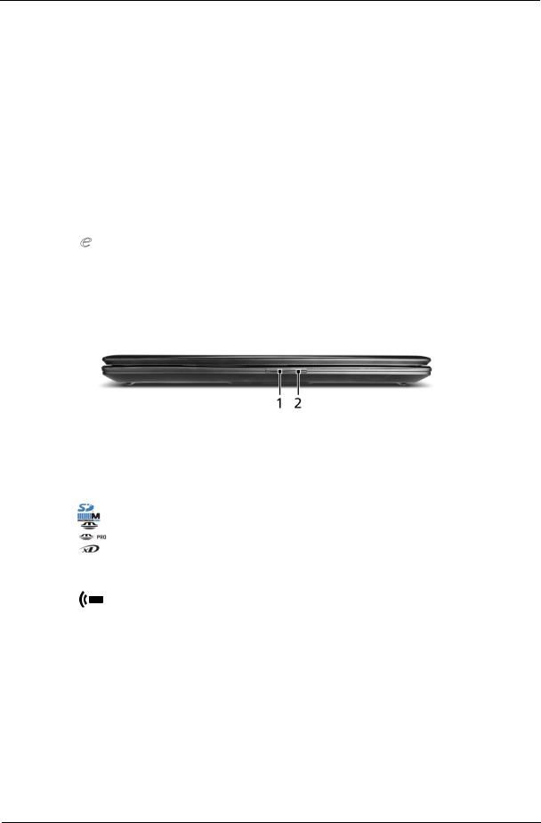
Closed Front View
|
Icon |
Item |
Description |
|
|
|
|
1 |
|
6-in-1 card reader |
Accepts Secure Digital (SD), MultiMediaCard |
|
|
|
(MMC),MultiMediaCardplus (MMCplus™), Memory Stick |
|
|
|
(MS), Memory Stick PRO (MS PRO), xD-Picture Card |
|
|
|
(xD). |
|
|
|
Note: Push to remove/install the card. Only one card can |
|
|
|
operate at any given time. |
|
|
|
|
2 |
|
CIR receiver |
Receives signals from a remote control. |
|
|
|
|
Chapter 1 |
7 |
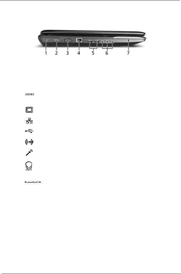
Left View
# |
|
|
|
|
|
Icon |
Item |
Description |
|
|
|
|
|
|
|
|
|
|
|
1 |
|
|
|
|
|
|
|
DC-in jack |
Connects to an AC adapter. |
|
|
|
|
|
|
|
|||
|
|
|
|
|
|
|
|
|
|
|
|
|
|
|
|
|
|
|
|
2 |
HDMI |
HDMI port |
Supports high definition digital video connections. |
||||||
|
|
|
|
|
|
|
|
|
|
3 |
|
|
|
|
|
|
|
External display |
Connects to a display device (e.g., external monitor, LCD |
|
|
|
|
|
|
|
|
(VGA) port |
projector). |
|
|
|
|
|
|
|
|
|
|
4 |
|
|
|
|
|
|
|
Ethernet (RJ-45) |
Connects to an Ethernet 10/100/1000-based network. |
|
|
|
|
|
|
|
|
port |
|
|
|
|
|
|
|
|
|
|
|
5 |
|
|
|
|
|
|
|
USB 2.0 port |
Connect to USB 2.0 devices (e.g., USB mouse, USB |
|
|
|
|
|
|
|
|
|
camera). |
|
|
|
|
|
|
|
|
|
|
6 |
|
|
|
|
|
|
|
Line-in jack |
Accepts audio line-in devices (e.g., audio CD player, |
|
|
|
|
|
|
|
|
|
stereo walkman, mp3 player) |
|
|
|
|
|
|
|
|
|
|
|
|
|
|
|
|
|
|
Microphone jack |
Accepts inputs from external microphones. |
|
|
|
|
|
|
|
|
|
|
|
|
|
|
|
|
|
|
Headphones/ |
Connects to audio line-out devices |
|
|
|
|
|
|
|
|
speaker/line-out |
(e.g., speakers, headphones). |
|
|
|
|
|
|
|
|
jack with |
|
|
|
|
|
|
|
|
|
|
|
|
|
|
|
|
|
|
|
|
|
|
|
|
|
|
|
|
|
S/PDIF support |
|
|
|
|
|
|
|
|
|
|
|
7 |
|
|
|
|
|
|
|
ExpressCard/54 |
Accepts one ExpressCard/54 module. |
|
|
|
|
|
|
|
|
slot |
|
|
|
|
|
|
|
|
|
|
|
8 |
Chapter 1 |
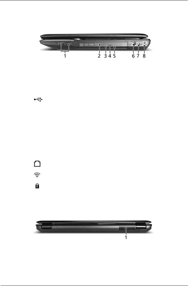
Right View
|
Icon |
Item |
Description |
|
|
|
|
1 |
|
USB 2.0 port |
Connects to USB 2.0 devices |
|
|
|
(e.g., USB mouse, USB camera). |
|
|
|
|
2 |
|
Optical drive |
Internal optical drive; accepts CDs or DVDs. |
|
|
|
|
3 |
|
Optical disk access |
Lights up when the optical drive is active. |
|
|
indicator |
|
|
|
|
|
4 |
|
Optical drive eject |
Ejects the optical disk from the drive. |
|
|
button |
|
|
|
|
|
5 |
|
Emergency eject hole |
Ejects the optical drive tray when the computer is |
|
|
|
turned off. |
|
|
|
Note: Insert a paper clip to the emergency eject |
|
|
|
hole to eject the optical drive tray when the |
|
|
|
computer is off. |
|
|
|
|
6 |
|
Modem |
Connects to a phone line. |
|
|
(RJ-11) port |
|
|
|
|
|
7 |
|
RF-in port |
Accepts input signals from digital TV-tuner devices. |
|
|
|
(only for certain models) |
|
|
|
|
8 |
|
Kensington lock slot |
Connects to a Kensington-compatible computer |
|
|
|
security lock. |
|
|
|
|
Rear View
# |
Item |
Description |
1 |
Ventilation slots |
Enable the computer to stay cool, even after prolonged use. |
|
|
|
Chapter 1 |
9 |
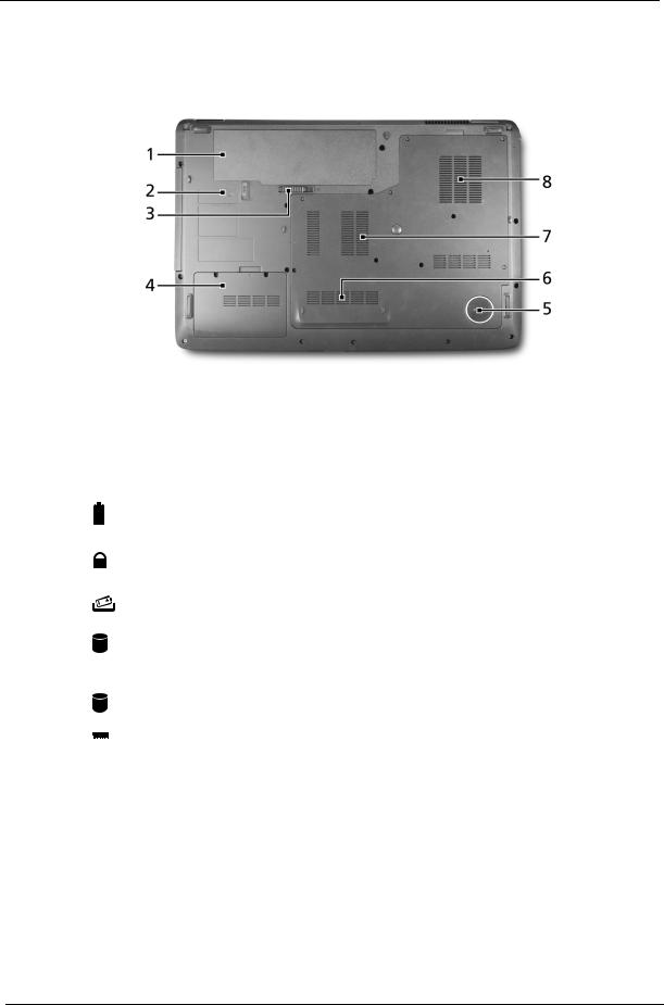
Bottom View
|
|
|
Icon |
Item |
Description |
|
|
|
|
|
|
1 |
|
|
|
Battery bay |
Houses the computer's battery pack. |
|
|
|
|
|
|
|
|
|
|
|
|
2 |
|
|
|
Battery lock |
Locks the battery in position. |
|
|
|
|
|
|
3 |
|
|
|
Battery release |
Releases the battery for removal. |
|
|
|
|
latch |
|
|
|
|
|
|
|
4 |
|
|
|
Hard disk bay- |
Houses the computer's hard disk (secured with screws) |
|
|
|
|
Secondary |
(only for certain models). |
|
|
|
|
|
|
5 |
|
|
|
Subwoofer |
Emits low frequency sound output. |
|
|
|
|
|
|
6 |
|
|
|
Hard disk bay- |
Houses the computer's hard disk |
|
|
|
|
Main |
(secured with screws). |
|
|
|
|
|
|
7 |
|
|
|
Memory |
Houses the computer's main memory. |
|
|
|
|
compartment |
|
|
|
|
|
|
|
8 |
|
|
|
Ventilation slots |
Enable the computer to stay cool, even after prolonged |
|
|
|
|
and cooling fan |
use. |
|
|
|
|
|
Note: Do not cover or obstruct the opening of the fan. |
|
|
|
|
|
|
10 |
Chapter 1 |
Indicators
The computer has several easy-to-read status indicators. The front panel indicators are visible even when the computer cover is closed.
|
|
|
Icon |
Function |
Description |
|
|
|
|
HDD |
Indicates when the hard disk drive is |
|
|
|
|
|
active. |
|
|
|
|
|
|
|
|
|
|
Num Lock |
Lights up when Num Lock is |
|
|
|
|
|
activated. |
|
|
|
|
|
|
|
|
|
|
|
|
|
|
|
|
Caps Lock |
Lights up when Caps Lock is |
|
|
|
|
|
activated. |
|
|
|
|
|
|
|
|
|
|
|
|
|
|
|
|
Power |
Indicates the computer's power |
|
|
|
|
|
status. |
|
|
|
|
|
|
|
|
|
|
Battery |
Indicates the computer's battery |
|
|
|
|
|
status. |
|
|
|
|
|
|
NOTE: 1. Charging: The light shows amber when the battery is charging. 2. Fully charged: The light shows green when in AC mode.
Easy-Launch Buttons
Located beside the keyboard are application buttons. These buttons are called easy-launch buttons. They are: WLAN, Internet, email, Bluetooth, Arcade and Acer Empowering Technology.
The mail and Web browser buttons are pre-set to email and Internet programs, but can be reset by users. To set the Web browser, mail and programmable buttons, run the Acer Launch Manager.You can access the Launch Manager by clicking on Start, All Programs, and then Launch Manager to start the application.
Icon |
Function |
Description |
|
Wireless communication |
Enables/disables the wireless function. Indicates the status |
|
button/indicator |
of wireless LAN communication. |
|
(manufacturing option) |
|
|
|
|
VOL+ |
Volume up |
Increases the sound volume. |
|
|
|
VOL- |
Volume down |
Decreases the sound volume. |
|
|
|
|
Bluetooth communication |
Enables/disables the Bluetooth function. Indicates the |
|
button/indicator |
status of Bluetooth communication. |
|
(manufacturing option) |
|
|
|
|
|
Acer Empowering |
Launch Acer Empowering Technology (user- |
|
Technology |
programmable) |
|
|
|
Chapter 1 |
11 |

Touchpad basics (with two-click buttons)
The following items show you how to use the touchpad with two-click buttons.
1 |
2 |
3 |
•Move your finger across the touchpad (1) to move the cursor.
•Press the left (2) and right (3) buttons located beneath the touchpad to perform selection and execution functions. These two buttons are similar to the left and right buttons on a mouse. Tapping on the touchpad is the same as clicking the left button.
Function |
Left button (2) |
Right button (3) |
Main touchpad (1) |
|
|
|
|
Execute |
Quickly click twice. |
|
Tap twice (at the same speed as double-clicking |
|
|
|
a mouse button). |
|
|
|
|
Select |
Click once. |
|
Tap once. |
|
|
|
|
Drag |
Click and hold, then use |
|
Tap twice (at the same speed as double-clicking |
|
finger on the touchpad |
|
a mouse button); rest your finger on the touchpad |
|
to drag the cursor. |
|
on the second tap and drag the cursor. |
|
|
|
|
Access |
|
Click once. |
|
context menu |
|
|
|
|
|
|
|
NOTE: Illustrations for reference only. The exact configuration of your PC depends on the model purchased.
NOTE: When using the touchpad, keep it — and your fingers — dry and clean. The touchpad is sensitive to finger movement; hence, the lighter the touch, the better the response. Tapping harder will not increase the touchpad's responsiveness.
NOTE: By default, vertical and horizontal scrolling is enabled on your touchpad. It can be disabled under Mouse settings in Windows Control Panel.
12 |
Chapter 1 |

Using the Keyboard
The keyboard has full-sized keys and an embedded numeric keypad, separate cursor, lock, Windows, function and special keys.
Lock Keys and embedded numeric keypad
The keyboard has three lock keys which you can toggle on and off.
Lock key |
Description |
|
|
Caps Lock |
When Caps Lock is on, all alphabetic characters typed are |
|
in uppercase. |
|
|
Num Lock |
When Num Lock is on, the embedded keypad is in numeric mode. The keys |
<Fn> + <F11> |
function as a calculator (complete with the arithmetic operators +, -, *, and /). |
|
Use this mode when you need to do a lot of numeric data entry. A better solution |
|
would be to connect an external keypad. |
|
NOTE: <Fn> + <F11> works only for certain models. |
|
|
Scroll Lock <Fn> + |
When Scroll Lock is on, the screen moves one line up or down when you press |
<F12> |
the up or down arrow keys respectively. Scroll Lock does not work with some |
|
applications. |
|
|
The embedded numeric keypad functions like a desktop numeric keypad. It is indicated by small characters located on the upper right corner of the key caps. To simplify the keyboard legend, cursor-control key symbols are not printed on the keys.
Desired access |
Num Lock on |
Num Lock off |
|
|
|
Number keys on |
Type numbers in a normal manner. |
|
embedded keypad |
|
|
|
|
|
Cursor-control keys on |
Hold <Shift> while using cursor- |
Hold <Fn> while using cursor- |
embedded keypad |
control keys. |
control keys. |
|
|
|
Main keyboard keys |
Hold <Fn> while typing letters on |
Type the letters in a normal |
|
embedded keypad. |
manner. |
|
|
|
Chapter 1 |
13 |
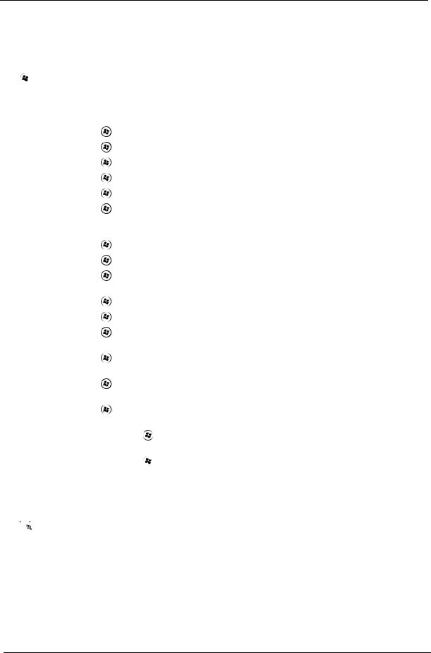
Windows Keys
The keyboard has two keys that perform Windows-specific functions.
|
|
|
Key |
Description |
|
|
|
|
|
|
|
|
Windows |
Pressed alone, this key has the same effect as |
|
|
|
key |
clicking on the Windows Start button; it launches the |
|
|
|
|
Start menu. |
|
|
|
|
It can also be used with other keys to provide a |
|
|
|
|
variety of functions: |
|
|
|
|
< >: Open or close the Start menu |
|
|
|
|
< > + <D>: Display the desktop |
|
|
|
|
< > + <E>: Open Windows Explore |
|
|
|
|
< > + <F>: Search for a file or folder |
|
|
|
|
< > + <G>: Cycle through Sidebar gadgets |
|
|
|
|
< > + <L>: Lock your computer (if you are |
|
|
|
|
connected to a network domain), or switch users (if |
|
|
|
|
you're not connected to a network domain) |
|
|
|
|
< > + <M>: Minimizes all windows |
|
|
|
|
< > + <R>: Open the Run dialog box |
|
|
|
|
< > + <T>: Cycle through programs on the |
|
|
|
|
taskbar |
|
|
|
|
< > + <U>: Open Ease of Access Center |
|
|
|
|
< > + <X>: Open Windows Mobility Center |
|
|
|
|
< > + <BREAK>: Display the System Properties |
|
|
|
|
dialog box |
|
|
|
|
< > + <SHIFT+M>: Restore minimized windows |
|
|
|
|
to the desktop |
|
|
|
|
< > + <TAB>: Cycle through programs on the |
|
|
|
|
taskbar by using Windows Flip 3-D |
|
|
|
|
< > + <SPACEBAR>: Bring all gadgets to the |
|
|
|
|
front and select Windows Sidebar |
|
|
|
|
<CTRL> + < > + <F>: Search for computers (if |
|
|
|
|
you are on a network) |
|
|
|
|
<CTRL> + < > + <TAB>: Use the arrow keys to |
|
|
|
|
cycle through programs on the taskbar by using |
|
|
|
|
Windows Flip 3-D |
|
|
|
|
Note: Depending on your edition of Windows Vista, |
|
|
|
|
some shortcuts may not function as described. |
|
|
|
|
|
|
|
|
Application |
This key has the same effect as clicking the right |
|
|
|
||
|
|
|
key |
mouse button; it opens the application's context |
|
|
|
||
|
|
|
|
menu. |
|
|
|
|
|
14 |
Chapter 1 |
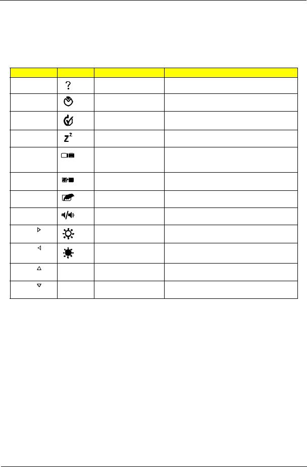
Hot Keys
The computer employs hotkeys or key combinations to access most of the computer’s controls like screen brightness, volume output and the BIOS utility.
To activate hot keys, press and hold the <Fn> key before pressing the other key in the hotkey combination.
Hotkey |
|
Icon |
Function |
Description |
<Fn> + <F1> |
|
Hotkey help |
Displays help on hotkeys. |
|
<Fn> + <F2> |
|
Acer eSettings |
Launches Acer eSettings in Acer Empowering |
|
|
|
|
|
Technology. |
<Fn> + <F3> |
|
Acer ePower |
Launches Acer ePower Management in Acer |
|
|
|
|
Management |
Empowering Technology. |
<Fn> + <F4> |
|
Sleep |
Puts the computer in Sleep mode. |
|
<Fn> + <F5> |
|
Display toggle |
Switches display output between the display |
|
|
|
|
|
screen, external monitor (if connected) and |
|
|
|
|
both. |
<Fn> + <F6> |
|
Screen blank |
Turns the display screen backlight off to save |
|
|
|
|
|
power. Press any key to return. |
<Fn> + <F7> |
|
Touchpad toggle |
Turns the internal touchpad on and off. |
|
<Fn> + <F8> |
|
Speaker toggle |
Turns the speakers on and off. |
|
<Fn> + < |
> |
|
Brightness up |
Increases the screen brightness. |
<Fn> + < |
> |
|
Brightness down |
Decreases the screen brightness. |
<Fn> + < |
> |
|
Volume up |
Increases the sound volume |
|
|
|
|
(only for certain models). |
<Fn> + < |
> |
|
Volume down |
Decreases the sound volume |
|
|
|
|
(only for certain models). |
Chapter 1 |
15 |

Special Key (only for certain models)
You can locate the Euro symbol and the US dollar sign at the upper-center and/or bottom-right of your keyboard.
The Euro symbol
1.Open a text editor or word processor.
2.Either press < > at the bottom-right of the keyboard, or hold <Alt Gr> and then press the <5> key at the upper-center of the keyboard.
NOTE: Some fonts and software do not support the Euro symbol. Please refer to www.microsoft.com/ typography/faq/faq12.htm for more information.
The US dollar sign
1.Open a text editor or word processor.
2.Either press <  > at the bottom-right of the keyboard, or hold <Shift> and then press the <4> key at the upper-center of the keyboard.
NOTE: This function varies according to the language settings.
16 |
Chapter 1 |
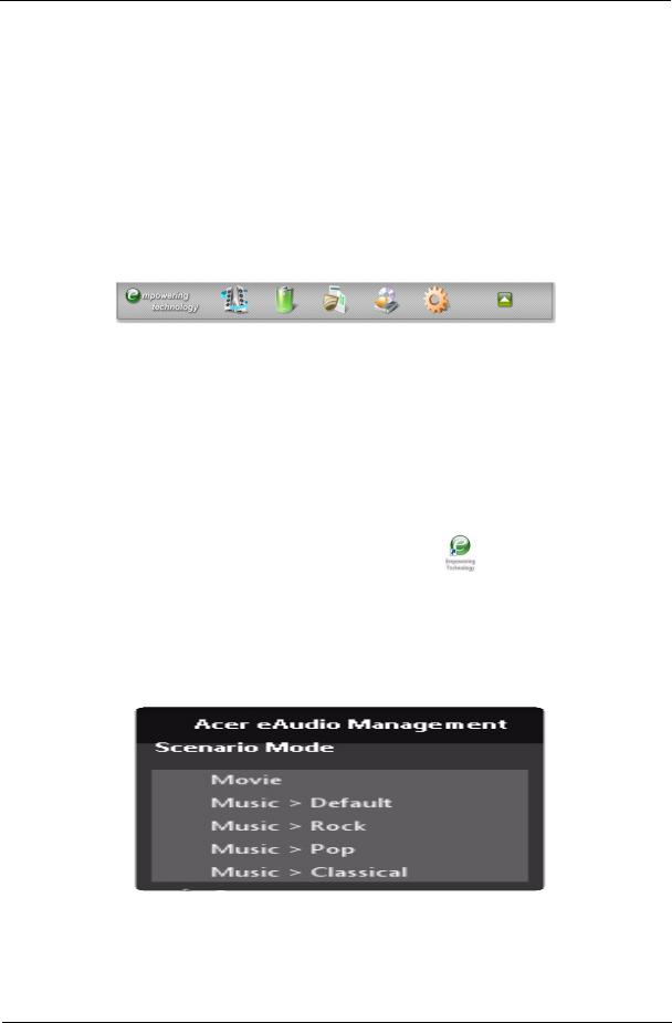
Acer Empowering Technology
The Empowering Technology toolbar makes it easy for you to access frequently used functions and manage your new Acer system. Activated by pressing the Empowering Key, it provides access to the following utilities:
NOTE: The following content is for general reference only. Actual product specifications may vary.
•Acer eAudio Management allows you to easily control the enhanced sound effects of Dolby Home Theater on your system (only for certain models).
•Acer ePower Management optimizes battery usage via customizable power plans.
•Acer eDataSecurity Management protects data with passwords and encryption (only for certain models).
•Acer eRecovery Management backs up and recovers data flexibly, reliably and completely.
•Acer eSettings Management accesses system information and adjusts settings easily.
For more information, right-click on the Empowering Technology toolbar, then select Help. For help with a particular utility, launch the utility and click the  icon at the bottom of the active window.
Launching Acer Empowering Technology
To launch Acer Empowering Technology:
1.Press the Empowering Key to display the Acer Empowering Technology toolbar on the desktop.
2.To hide the toolbar, press the Empowering Key again or click the hide button  on the toolbar. You may also launch Acer Empowering Technology by running the program from the Acer Empowering
Technology program group in the Start menu, or by double-clicking the |
icon if you have created a |
desktop shortcut.
To launch Acer Empowering Technology applications:
1.On the Acer Empowering Technology toolbar, click the icon that corresponds to the application you want to launch.
2.When you mouse over an application icon, a quick menu appears below the toolbar. The quick menu allows you to perform certain tasks simply and quickly.
3.You may also run the application by selecting it from the Acer Empowering Technology program group in the Start menu.
NOTE: You may also double-click or right-click  to run Acer eAudio Management, and right-click
  to run Acer ePower Management from the system tray.
Chapter 1 |
17 |
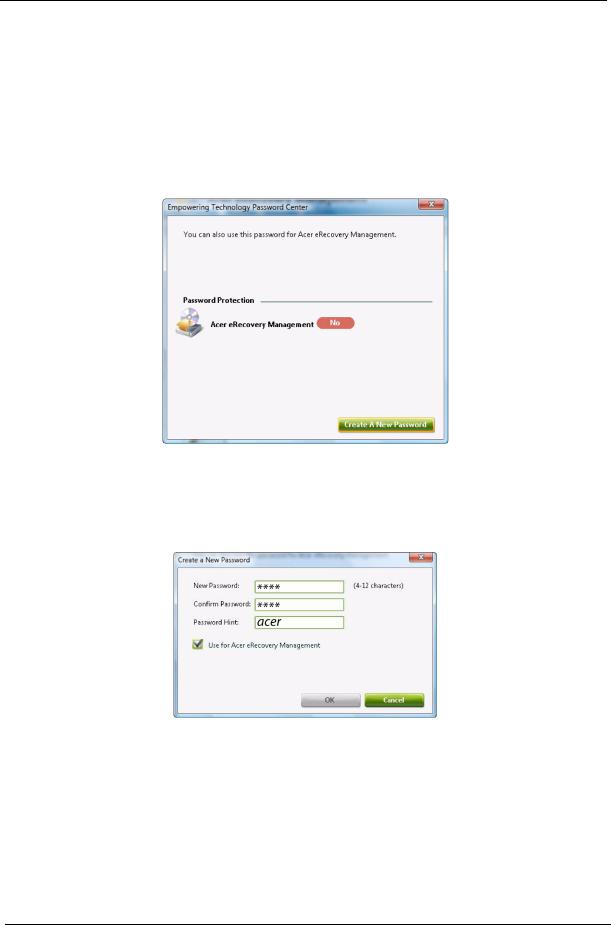
Empowering Technology password
You must set the Empowering Technology password to use the password protection feature of Acer eRecovery Management to protect your data.
To set the Empowering Technology password:
1.Launch Acer eRecovery Management.
2.Click the Restore tab.
3.Click Password settings. The Empowering Technology Password Center dialogue box pops up.
4.Click Create a new password.
5.In the Create a New Password dialogue box, key in and confirm your password in the appropriate boxes. Your password should have a minimum of 4 and a maximum of 12 characters.
6.Enter a password hint that will help you remember your password.
7.Make sure the box Use for Acer eRecovery Management is checked.
8.Click OK to set the password.
18 |
Chapter 1 |
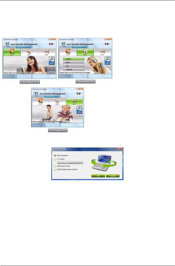
Acer eAudio Management  (only for certain models)
Acer eAudio Management allows you to easily control the enhanced sound effects of Dolby Home Theater on your system. Select Movie or Game mode to experience the awesome realism of 5.1-channel audio output from the speakers fitted to your system via Dolby Surround sound technology. Music mode lets you enjoy your favorite tunes, in vivid detail.
To choose your playback device, click the  icon on the upper right side of the Acer eAudio Management window.
Chapter 1 |
19 |

Acer ePower Management 
Acer ePower Management features a straightforward user interface for configuring your power management options. To access this utility, select Acer ePower Management from the Empowering Technology toolbar, run the program from the Acer Empowering Technology program group in Start menu, or right-click the Windows power icon in the system tray and select Acer ePower Management.
Using power plans
Acer ePower Management comes with three predefined power plans: Balanced, High performance and
Power saver.
View and adjust settings for On Battery and Plugged In modes by clicking the appropriate tabs. For more power options, click  in the Acer ePower Management utility, or right-click the Windows power icon in the system tray and select Power Options.
You can also create customized power plans. You can create, switch between, edit, delete and restore power plans, as described below.
To create a new power plan:
Creating customized power plans allows you to save and quickly switch to a personalized set of power options.
1.Click the New power plan option or icon  .
.
2.Enter a name for your new power plan.
3.Choose a predefined power plan to base your customized plan on.
4.If necessary, change the display, sleep and hibernation settings you want your computer to use.
5.Click OK to save your new power plan.
To switch between power plans:
1.Move your mouse over the Acer ePower Management  application on the Acer Empowering Technology toolbar. The quick menu appears.
Select the power plan you want to switch to.
2.You may also switch between power plans by launching the Acer ePower Management application. Select the power plan you wish to switch to, then click Apply.
To edit a power plan:
Editing a power plan allows you to adjust system settings like LCD brightness, CPU speed and Graphics power mode (only for certain models).
1.Switch to the power plan you wish to edit.
2.Adjust settings as required.
3.Click Apply or Save to save your new settings.
NOTE: You can revert to the default settings of the predefined power plans by clicking the Restore button.
To delete a power plan:
You cannot delete the power plan you are currently using. The active power plan will mark with  in upper left corner of power plan icon. If you want to delete the active power plan, switch to another one first.
1.Select the power plan you wish to delete.
2.Click the Delete this plan icon. 
NOTE: You cannot delete the predefined power plans, but you can modify the settings of the predefined power plans.
20 |
Chapter 1 |
 Loading...