

ABB ACS380 Hardware Manual
ABB machinery drives
ABB machinery drives
Hardware manual
Hardware manual
ACS380 drives
ACS380 drives

List of related manuals
Drive manuals and guides Code (English)
ACS380 drives hardware manual 3AXD50000029274
ACS380 quick installation and start-up guide 3AXD50000018553
ACS380 user interface guide 3AXD50000022224
ACS380 firmware manual 3AXD50000029275
Option manuals and guides
ACS-AP-x Assistant control panel user’s manual 3AUA0000085685
Tool and maintenance manuals and guides
Drive composer PC tool user's manual 3AUA0000094606
Converter module capacitor reforming instructions
You can find manuals and other product documents in PDF format on the Internet. Refer to Document library
on the Internet on the inside of the back cover. For manuals not available in the Document library, contact
your local ABB representative.
The QR code opens an online listing of the manuals applicable to this product.
3BFE64059629
Hardware manual
ACS380 drives
Table of contents
1. Safety instructions
4. Mechanical installation
6. Electrical installation
2016 ABB Oy. All Rights Reserved.
3AXD50000029274 Rev B
EN
EFFECTIVE: 2016-04-04


Table of contents 5
Table of contents
List of related manuals . . . . . . . . . . . . . . . . . . . . . . . . . . . . . . . . . . . . . . . . . . . . . . . . . . . . . . . 2
1. Safety instructions
Contents of this chapter . . . . . . . . . . . . . . . . . . . . . . . . . . . . . . . . . . . . . . . . . . . . . . . . . . . . . . 13
Use of warnings and notes in this manual . . . . . . . . . . . . . . . . . . . . . . . . . . . . . . . . . . . . . . . . 13
General safety in installation, start-up and maintenance . . . . . . . . . . . . . . . . . . . . . . . . . . . . . 14
Electrical safety in installation, start-up and maintenance . . . . . . . . . . . . . . . . . . . . . . . . . . . . 15
Precautions before electrical work . . . . . . . . . . . . . . . . . . . . . . . . . . . . . . . . . . . . . . . . . . 15
Additional instructions and notes . . . . . . . . . . . . . . . . . . . . . . . . . . . . . . . . . . . . . . . . . . . 16
Grounding . . . . . . . . . . . . . . . . . . . . . . . . . . . . . . . . . . . . . . . . . . . . . . . . . . . . . . . . . . . . . 17
Additional instructions for permanent magnet motor drives . . . . . . . . . . . . . . . . . . . . . . . . . . 18
Safety in installation, start-up and maintenance . . . . . . . . . . . . . . . . . . . . . . . . . . . . . . . . 18
General safety in operation . . . . . . . . . . . . . . . . . . . . . . . . . . . . . . . . . . . . . . . . . . . . . . . . . . . 19
2. Introduction to the manual
Contents of this chapter . . . . . . . . . . . . . . . . . . . . . . . . . . . . . . . . . . . . . . . . . . . . . . . . . . . . . . 21
Applicability . . . . . . . . . . . . . . . . . . . . . . . . . . . . . . . . . . . . . . . . . . . . . . . . . . . . . . . . . . . . . . . 21
Target audience . . . . . . . . . . . . . . . . . . . . . . . . . . . . . . . . . . . . . . . . . . . . . . . . . . . . . . . . . . . . 21
Purpose of the manual . . . . . . . . . . . . . . . . . . . . . . . . . . . . . . . . . . . . . . . . . . . . . . . . . . . . . . 21
Contents of this manual . . . . . . . . . . . . . . . . . . . . . . . . . . . . . . . . . . . . . . . . . . . . . . . . . . . . . . 22
Related documents . . . . . . . . . . . . . . . . . . . . . . . . . . . . . . . . . . . . . . . . . . . . . . . . . . . . . . . . . 22
Categorization by frame (size) . . . . . . . . . . . . . . . . . . . . . . . . . . . . . . . . . . . . . . . . . . . . . . . . . 22
Quick installation and commissioning flowchart . . . . . . . . . . . . . . . . . . . . . . . . . . . . . . . . . . . 23
Safety
3. Hardware description
Contents of this chapter . . . . . . . . . . . . . . . . . . . . . . . . . . . . . . . . . . . . . . . . . . . . . . . . . . . . . . 27
General description . . . . . . . . . . . . . . . . . . . . . . . . . . . . . . . . . . . . . . . . . . . . . . . . . . . . . . . . . 27
Product variants . . . . . . . . . . . . . . . . . . . . . . . . . . . . . . . . . . . . . . . . . . . . . . . . . . . . . . . . . . . . 27
Hardware overview . . . . . . . . . . . . . . . . . . . . . . . . . . . . . . . . . . . . . . . . . . . . . . . . . . . . . . . . . 28
Control connections . . . . . . . . . . . . . . . . . . . . . . . . . . . . . . . . . . . . . . . . . . . . . . . . . . . . . . . . . 29
Standard variant (I/O and Modbus) (ACS380-04xS) . . . . . . . . . . . . . . . . . . . . . . . . . . . . . 29
Configured variant (ACS380-04xC) . . . . . . . . . . . . . . . . . . . . . . . . . . . . . . . . . . . . . . . . . 30
Base variant (ACS380-04xN) . . . . . . . . . . . . . . . . . . . . . . . . . . . . . . . . . . . . . . . . . . . . . . 31
Side-mounted options . . . . . . . . . . . . . . . . . . . . . . . . . . . . . . . . . . . . . . . . . . . . . . . . . . . . 32
Assistant control panel options . . . . . . . . . . . . . . . . . . . . . . . . . . . . . . . . . . . . . . . . . . . . . . . . 32
PC connection . . . . . . . . . . . . . . . . . . . . . . . . . . . . . . . . . . . . . . . . . . . . . . . . . . . . . . . . . . . . . 32
Drive labels . . . . . . . . . . . . . . . . . . . . . . . . . . . . . . . . . . . . . . . . . . . . . . . . . . . . . . . . . . . . . . . 33
Model information label . . . . . . . . . . . . . . . . . . . . . . . . . . . . . . . . . . . . . . . . . . . . . . . . . . . 33
Type designation label . . . . . . . . . . . . . . . . . . . . . . . . . . . . . . . . . . . . . . . . . . . . . . . . . . . 34
Type designation key . . . . . . . . . . . . . . . . . . . . . . . . . . . . . . . . . . . . . . . . . . . . . . . . . . . . . . . . 35
Operation principle . . . . . . . . . . . . . . . . . . . . . . . . . . . . . . . . . . . . . . . . . . . . . . . . . . . . . . . . . 37
Control panel . . . . . . . . . . . . . . . . . . . . . . . . . . . . . . . . . . . . . . . . . . . . . . . . . . . . . . . . . . . . . . 38
Home view . . . . . . . . . . . . . . . . . . . . . . . . . . . . . . . . . . . . . . . . . . . . . . . . . . . . . . . . . . . . 39
Message view . . . . . . . . . . . . . . . . . . . . . . . . . . . . . . . . . . . . . . . . . . . . . . . . . . . . . . . . . . 40

6 Table of contents
Options view . . . . . . . . . . . . . . . . . . . . . . . . . . . . . . . . . . . . . . . . . . . . . . . . . . . . . . . . . . . 40
Menu . . . . . . . . . . . . . . . . . . . . . . . . . . . . . . . . . . . . . . . . . . . . . . . . . . . . . . . . . . . . . . . . 40
4. Mechanical installation
Contents of this chapter . . . . . . . . . . . . . . . . . . . . . . . . . . . . . . . . . . . . . . . . . . . . . . . . . . . . . 41
Examining the installation site . . . . . . . . . . . . . . . . . . . . . . . . . . . . . . . . . . . . . . . . . . . . . . . . 42
Required tools . . . . . . . . . . . . . . . . . . . . . . . . . . . . . . . . . . . . . . . . . . . . . . . . . . . . . . . . . . . . 42
Unpacking the delivery . . . . . . . . . . . . . . . . . . . . . . . . . . . . . . . . . . . . . . . . . . . . . . . . . . . . . . 42
Installing the drive . . . . . . . . . . . . . . . . . . . . . . . . . . . . . . . . . . . . . . . . . . . . . . . . . . . . . . . . . 43
To install the drive with screws . . . . . . . . . . . . . . . . . . . . . . . . . . . . . . . . . . . . . . . . . . . . 43
To install the drive to a DIN installation rail . . . . . . . . . . . . . . . . . . . . . . . . . . . . . . . . . . . 44
5. Planning the electrical installation
Contents of this chapter . . . . . . . . . . . . . . . . . . . . . . . . . . . . . . . . . . . . . . . . . . . . . . . . . . . . . 45
Selecting the supply disconnecting device . . . . . . . . . . . . . . . . . . . . . . . . . . . . . . . . . . . . . . . 45
European Union . . . . . . . . . . . . . . . . . . . . . . . . . . . . . . . . . . . . . . . . . . . . . . . . . . . . . . . . 45
Other regions . . . . . . . . . . . . . . . . . . . . . . . . . . . . . . . . . . . . . . . . . . . . . . . . . . . . . . . . . . 46
Checking the compatibility of the motor and drive . . . . . . . . . . . . . . . . . . . . . . . . . . . . . . . . . 46
Selecting the power cables . . . . . . . . . . . . . . . . . . . . . . . . . . . . . . . . . . . . . . . . . . . . . . . . . . 46
Typical power cable sizes . . . . . . . . . . . . . . . . . . . . . . . . . . . . . . . . . . . . . . . . . . . . . . . . 47
Recommended power cable types . . . . . . . . . . . . . . . . . . . . . . . . . . . . . . . . . . . . . . . . . . 48
Power cable types for limited use . . . . . . . . . . . . . . . . . . . . . . . . . . . . . . . . . . . . . . . . . . 48
Not allowed power cable types . . . . . . . . . . . . . . . . . . . . . . . . . . . . . . . . . . . . . . . . . . . . 48
Motor cable shield . . . . . . . . . . . . . . . . . . . . . . . . . . . . . . . . . . . . . . . . . . . . . . . . . . . . . . 49
Additional US requirements . . . . . . . . . . . . . . . . . . . . . . . . . . . . . . . . . . . . . . . . . . . . . . . 49
Selecting the control cables . . . . . . . . . . . . . . . . . . . . . . . . . . . . . . . . . . . . . . . . . . . . . . . . . . 51
Shielding . . . . . . . . . . . . . . . . . . . . . . . . . . . . . . . . . . . . . . . . . . . . . . . . . . . . . . . . . . . . . 51
Signals in separate cables . . . . . . . . . . . . . . . . . . . . . . . . . . . . . . . . . . . . . . . . . . . . . . . . 51
Signals that can be run in the same cable . . . . . . . . . . . . . . . . . . . . . . . . . . . . . . . . . . . . 51
Relay cable . . . . . . . . . . . . . . . . . . . . . . . . . . . . . . . . . . . . . . . . . . . . . . . . . . . . . . . . . . . 51
Drive composer PC tool cable . . . . . . . . . . . . . . . . . . . . . . . . . . . . . . . . . . . . . . . . . . . . . 51
Routing the cables . . . . . . . . . . . . . . . . . . . . . . . . . . . . . . . . . . . . . . . . . . . . . . . . . . . . . . . . . 52
Separate control cable ducts . . . . . . . . . . . . . . . . . . . . . . . . . . . . . . . . . . . . . . . . . . . . . . 53
Continuous motor cable shield or conduit . . . . . . . . . . . . . . . . . . . . . . . . . . . . . . . . . . . . 53
Implementing short-circuit protection . . . . . . . . . . . . . . . . . . . . . . . . . . . . . . . . . . . . . . . . . . . 53
Protecting the drive and input power cable in short-circuits . . . . . . . . . . . . . . . . . . . . . . . 53
Protecting the motor and motor cable in short-circuits . . . . . . . . . . . . . . . . . . . . . . . . . . . 53
Implementing thermal overload protection . . . . . . . . . . . . . . . . . . . . . . . . . . . . . . . . . . . . . . . 54
Protecting the drive, and the input power and motor cables against thermal overload . . 54
Protecting the motor against thermal overload . . . . . . . . . . . . . . . . . . . . . . . . . . . . . . . . 54
Protecting the drive against ground faults . . . . . . . . . . . . . . . . . . . . . . . . . . . . . . . . . . . . . . . 54
Residual current device compatibility . . . . . . . . . . . . . . . . . . . . . . . . . . . . . . . . . . . . . . . . 54
Implementing the emergency stop function . . . . . . . . . . . . . . . . . . . . . . . . . . . . . . . . . . . . . . 54
Implementing the Safe torque off function . . . . . . . . . . . . . . . . . . . . . . . . . . . . . . . . . . . . . . . 55
Using a safety switch between the drive and motor . . . . . . . . . . . . . . . . . . . . . . . . . . . . . . . . 55
Using a contactor between the drive and motor . . . . . . . . . . . . . . . . . . . . . . . . . . . . . . . . . . . 55
Protecting the contacts of relay outputs . . . . . . . . . . . . . . . . . . . . . . . . . . . . . . . . . . . . . . . . . 56

Table of contents 7
6. Electrical installation
Contents of this chapter . . . . . . . . . . . . . . . . . . . . . . . . . . . . . . . . . . . . . . . . . . . . . . . . . . . . . . 57
Warnings . . . . . . . . . . . . . . . . . . . . . . . . . . . . . . . . . . . . . . . . . . . . . . . . . . . . . . . . . . . . . . . . . 57
Required tools . . . . . . . . . . . . . . . . . . . . . . . . . . . . . . . . . . . . . . . . . . . . . . . . . . . . . . . . . . . . . 57
Measuring insulation . . . . . . . . . . . . . . . . . . . . . . . . . . . . . . . . . . . . . . . . . . . . . . . . . . . . . . . . 58
Drive . . . . . . . . . . . . . . . . . . . . . . . . . . . . . . . . . . . . . . . . . . . . . . . . . . . . . . . . . . . . . . . . . 58
Input power cable . . . . . . . . . . . . . . . . . . . . . . . . . . . . . . . . . . . . . . . . . . . . . . . . . . . . . . . 58
Motor and motor cable . . . . . . . . . . . . . . . . . . . . . . . . . . . . . . . . . . . . . . . . . . . . . . . . . . . 58
Brake resistor assembly . . . . . . . . . . . . . . . . . . . . . . . . . . . . . . . . . . . . . . . . . . . . . . . . . . 58
Compatibility with IT (ungrounded) and corner-grounded TN systems . . . . . . . . . . . . . . . . . . 59
EMC filter . . . . . . . . . . . . . . . . . . . . . . . . . . . . . . . . . . . . . . . . . . . . . . . . . . . . . . . . . . . . . 59
EMC filter disconnection . . . . . . . . . . . . . . . . . . . . . . . . . . . . . . . . . . . . . . . . . . . . . . . . . . 59
Ground-to-phase varistor . . . . . . . . . . . . . . . . . . . . . . . . . . . . . . . . . . . . . . . . . . . . . . . . . 59
Connecting the power cables . . . . . . . . . . . . . . . . . . . . . . . . . . . . . . . . . . . . . . . . . . . . . . . . . 60
Connection diagram . . . . . . . . . . . . . . . . . . . . . . . . . . . . . . . . . . . . . . . . . . . . . . . . . . . . . 60
Connection procedure . . . . . . . . . . . . . . . . . . . . . . . . . . . . . . . . . . . . . . . . . . . . . . . . . . . . 61
Connecting the control cables . . . . . . . . . . . . . . . . . . . . . . . . . . . . . . . . . . . . . . . . . . . . . . . . . 62
Default I/O connection diagram (ABB standard macro) . . . . . . . . . . . . . . . . . . . . . . . . . . 63
Fieldbus connection diagram . . . . . . . . . . . . . . . . . . . . . . . . . . . . . . . . . . . . . . . . . . . . . . 64
Control cable connection procedure . . . . . . . . . . . . . . . . . . . . . . . . . . . . . . . . . . . . . . . . . 66
Auxiliary voltage connection . . . . . . . . . . . . . . . . . . . . . . . . . . . . . . . . . . . . . . . . . . . . . . . . . . 67
Option modules . . . . . . . . . . . . . . . . . . . . . . . . . . . . . . . . . . . . . . . . . . . . . . . . . . . . . . . . . . . . 68
To install a front option . . . . . . . . . . . . . . . . . . . . . . . . . . . . . . . . . . . . . . . . . . . . . . . . . . . 68
To remove a front option . . . . . . . . . . . . . . . . . . . . . . . . . . . . . . . . . . . . . . . . . . . . . . . . . . 69
To install a side option . . . . . . . . . . . . . . . . . . . . . . . . . . . . . . . . . . . . . . . . . . . . . . . . . . . 69
To remove a side option . . . . . . . . . . . . . . . . . . . . . . . . . . . . . . . . . . . . . . . . . . . . . . . . . . 69
7. Installation checklist
Contents of this chapter . . . . . . . . . . . . . . . . . . . . . . . . . . . . . . . . . . . . . . . . . . . . . . . . . . . . . . 71
Warnings . . . . . . . . . . . . . . . . . . . . . . . . . . . . . . . . . . . . . . . . . . . . . . . . . . . . . . . . . . . . . . . . . 71
Checklist . . . . . . . . . . . . . . . . . . . . . . . . . . . . . . . . . . . . . . . . . . . . . . . . . . . . . . . . . . . . . . . . . 71
8. Maintenance
Contents of this chapter . . . . . . . . . . . . . . . . . . . . . . . . . . . . . . . . . . . . . . . . . . . . . . . . . . . . . . 73
Maintenance intervals . . . . . . . . . . . . . . . . . . . . . . . . . . . . . . . . . . . . . . . . . . . . . . . . . . . . . . . 74
Cleaning the heat sink . . . . . . . . . . . . . . . . . . . . . . . . . . . . . . . . . . . . . . . . . . . . . . . . . . . . . . . 75
Replacing the cooling fans . . . . . . . . . . . . . . . . . . . . . . . . . . . . . . . . . . . . . . . . . . . . . . . . . . . 76
To replace the cooling fan . . . . . . . . . . . . . . . . . . . . . . . . . . . . . . . . . . . . . . . . . . . . . . . . . 76
Servicing the capacitors . . . . . . . . . . . . . . . . . . . . . . . . . . . . . . . . . . . . . . . . . . . . . . . . . . . . . 78
Capacitor reforming . . . . . . . . . . . . . . . . . . . . . . . . . . . . . . . . . . . . . . . . . . . . . . . . . . . . . . 78
9. Technical data
Contents of this chapter . . . . . . . . . . . . . . . . . . . . . . . . . . . . . . . . . . . . . . . . . . . . . . . . . . . . . . 79
Ratings . . . . . . . . . . . . . . . . . . . . . . . . . . . . . . . . . . . . . . . . . . . . . . . . . . . . . . . . . . . . . . . . . . 80
IEC ratings . . . . . . . . . . . . . . . . . . . . . . . . . . . . . . . . . . . . . . . . . . . . . . . . . . . . . . . . . . . . 80
NEMA ratings . . . . . . . . . . . . . . . . . . . . . . . . . . . . . . . . . . . . . . . . . . . . . . . . . . . . . . . . . . 81
Definitions . . . . . . . . . . . . . . . . . . . . . . . . . . . . . . . . . . . . . . . . . . . . . . . . . . . . . . . . . . . . . 81
Sizing . . . . . . . . . . . . . . . . . . . . . . . . . . . . . . . . . . . . . . . . . . . . . . . . . . . . . . . . . . . . . . . . 81

8 Table of contents
Derating . . . . . . . . . . . . . . . . . . . . . . . . . . . . . . . . . . . . . . . . . . . . . . . . . . . . . . . . . . . . . . . . . 82
Surrounding air temperature derating, IP20 . . . . . . . . . . . . . . . . . . . . . . . . . . . . . . . . . . . 83
Switching frequency derating . . . . . . . . . . . . . . . . . . . . . . . . . . . . . . . . . . . . . . . . . . . . . . 83
Altitude derating . . . . . . . . . . . . . . . . . . . . . . . . . . . . . . . . . . . . . . . . . . . . . . . . . . . . . . . . 83
Fuses (IEC) . . . . . . . . . . . . . . . . . . . . . . . . . . . . . . . . . . . . . . . . . . . . . . . . . . . . . . . . . . . . . . 84
gG fuses . . . . . . . . . . . . . . . . . . . . . . . . . . . . . . . . . . . . . . . . . . . . . . . . . . . . . . . . . . . . . . 84
UL fuses . . . . . . . . . . . . . . . . . . . . . . . . . . . . . . . . . . . . . . . . . . . . . . . . . . . . . . . . . . . . . . 85
gR fuses . . . . . . . . . . . . . . . . . . . . . . . . . . . . . . . . . . . . . . . . . . . . . . . . . . . . . . . . . . . . . . 86
Dimensions and weights . . . . . . . . . . . . . . . . . . . . . . . . . . . . . . . . . . . . . . . . . . . . . . . . . . . . 87
Free space requirements . . . . . . . . . . . . . . . . . . . . . . . . . . . . . . . . . . . . . . . . . . . . . . . . . . . . 88
Losses, cooling data and noise . . . . . . . . . . . . . . . . . . . . . . . . . . . . . . . . . . . . . . . . . . . . . . . 88
Terminal data for the power cables . . . . . . . . . . . . . . . . . . . . . . . . . . . . . . . . . . . . . . . . . . . . 89
IEC . . . . . . . . . . . . . . . . . . . . . . . . . . . . . . . . . . . . . . . . . . . . . . . . . . . . . . . . . . . . . . . . . . 89
Terminal data for the control cables . . . . . . . . . . . . . . . . . . . . . . . . . . . . . . . . . . . . . . . . . . . . 90
EMC filters for Category C1 . . . . . . . . . . . . . . . . . . . . . . . . . . . . . . . . . . . . . . . . . . . . . . . . . . 91
Electric power network specification . . . . . . . . . . . . . . . . . . . . . . . . . . . . . . . . . . . . . . . . . . . . 92
Motor cable length . . . . . . . . . . . . . . . . . . . . . . . . . . . . . . . . . . . . . . . . . . . . . . . . . . . . . . 93
Motor connection data . . . . . . . . . . . . . . . . . . . . . . . . . . . . . . . . . . . . . . . . . . . . . . . . . . . . . . 93
Control connection data . . . . . . . . . . . . . . . . . . . . . . . . . . . . . . . . . . . . . . . . . . . . . . . . . . . . . 95
Brake resistor connection . . . . . . . . . . . . . . . . . . . . . . . . . . . . . . . . . . . . . . . . . . . . . . . . . . . . 96
Efficiency . . . . . . . . . . . . . . . . . . . . . . . . . . . . . . . . . . . . . . . . . . . . . . . . . . . . . . . . . . . . . . . . 96
Degrees of protection . . . . . . . . . . . . . . . . . . . . . . . . . . . . . . . . . . . . . . . . . . . . . . . . . . . . . . . 96
Ambient conditions . . . . . . . . . . . . . . . . . . . . . . . . . . . . . . . . . . . . . . . . . . . . . . . . . . . . . . . . . 97
Materials . . . . . . . . . . . . . . . . . . . . . . . . . . . . . . . . . . . . . . . . . . . . . . . . . . . . . . . . . . . . . . . . . 98
Applicable standards . . . . . . . . . . . . . . . . . . . . . . . . . . . . . . . . . . . . . . . . . . . . . . . . . . . . . . . 98
CE marking . . . . . . . . . . . . . . . . . . . . . . . . . . . . . . . . . . . . . . . . . . . . . . . . . . . . . . . . . . . . . . . 99
Compliance with the European Low Voltage Directive . . . . . . . . . . . . . . . . . . . . . . . . . . 99
Compliance with the European EMC Directive . . . . . . . . . . . . . . . . . . . . . . . . . . . . . . . . 99
Compliance with the European ROHS Directive . . . . . . . . . . . . . . . . . . . . . . . . . . . . . . . 99
Compliance with the European WEEE Directive . . . . . . . . . . . . . . . . . . . . . . . . . . . . . . . 99
Compliance with the European Machinery Directive . . . . . . . . . . . . . . . . . . . . . . . . . . . 100
Compliance with EN 61800-3:2004 + A1:2012 . . . . . . . . . . . . . . . . . . . . . . . . . . . . . . . . . . 101
Definitions . . . . . . . . . . . . . . . . . . . . . . . . . . . . . . . . . . . . . . . . . . . . . . . . . . . . . . . . . . . 101
Category C1 . . . . . . . . . . . . . . . . . . . . . . . . . . . . . . . . . . . . . . . . . . . . . . . . . . . . . . . . . . 101
Category C2 . . . . . . . . . . . . . . . . . . . . . . . . . . . . . . . . . . . . . . . . . . . . . . . . . . . . . . . . . . 101
Category C3 . . . . . . . . . . . . . . . . . . . . . . . . . . . . . . . . . . . . . . . . . . . . . . . . . . . . . . . . . . 102
Category C4 . . . . . . . . . . . . . . . . . . . . . . . . . . . . . . . . . . . . . . . . . . . . . . . . . . . . . . . . . . 103
UL marking . . . . . . . . . . . . . . . . . . . . . . . . . . . . . . . . . . . . . . . . . . . . . . . . . . . . . . . . . . . . . . 104
UL checklist . . . . . . . . . . . . . . . . . . . . . . . . . . . . . . . . . . . . . . . . . . . . . . . . . . . . . . . . . . 104
CSA marking . . . . . . . . . . . . . . . . . . . . . . . . . . . . . . . . . . . . . . . . . . . . . . . . . . . . . . . . . . . . 104
RCM marking . . . . . . . . . . . . . . . . . . . . . . . . . . . . . . . . . . . . . . . . . . . . . . . . . . . . . . . . . . . . 104
EAC marking . . . . . . . . . . . . . . . . . . . . . . . . . . . . . . . . . . . . . . . . . . . . . . . . . . . . . . . . . . . . 105
Disclaimers . . . . . . . . . . . . . . . . . . . . . . . . . . . . . . . . . . . . . . . . . . . . . . . . . . . . . . . . . . . . . . 105
Generic disclaimer . . . . . . . . . . . . . . . . . . . . . . . . . . . . . . . . . . . . . . . . . . . . . . . . . . . . . 105
Cyber security disclaimer . . . . . . . . . . . . . . . . . . . . . . . . . . . . . . . . . . . . . . . . . . . . . . . . 105
10. Dimension drawings
Frame R0 (230 V) . . . . . . . . . . . . . . . . . . . . . . . . . . . . . . . . . . . . . . . . . . . . . . . . . . . . . . . . . 108
Frame R0 (400 V) . . . . . . . . . . . . . . . . . . . . . . . . . . . . . . . . . . . . . . . . . . . . . . . . . . . . . . . . . 109
Frame R1 (230 V) . . . . . . . . . . . . . . . . . . . . . . . . . . . . . . . . . . . . . . . . . . . . . . . . . . . . . . . . . 110

Table of contents 9
Frame R1 (400 V) . . . . . . . . . . . . . . . . . . . . . . . . . . . . . . . . . . . . . . . . . . . . . . . . . . . . . . . . . 111
Frame R2 (230 V) . . . . . . . . . . . . . . . . . . . . . . . . . . . . . . . . . . . . . . . . . . . . . . . . . . . . . . . . . 112
Frame R2 (400 V) . . . . . . . . . . . . . . . . . . . . . . . . . . . . . . . . . . . . . . . . . . . . . . . . . . . . . . . . . 113
Frame R3 (400 V) . . . . . . . . . . . . . . . . . . . . . . . . . . . . . . . . . . . . . . . . . . . . . . . . . . . . . . . . . 114
11. Resistor braking
Contents of this chapter . . . . . . . . . . . . . . . . . . . . . . . . . . . . . . . . . . . . . . . . . . . . . . . . . . . . . 115
Operation principle and hardware description . . . . . . . . . . . . . . . . . . . . . . . . . . . . . . . . . . . . 115
Selecting the brake resistor . . . . . . . . . . . . . . . . . . . . . . . . . . . . . . . . . . . . . . . . . . . . . . . . . . 115
Reference brake resistors . . . . . . . . . . . . . . . . . . . . . . . . . . . . . . . . . . . . . . . . . . . . . . . . 117
Selecting and routing the brake resistor cables . . . . . . . . . . . . . . . . . . . . . . . . . . . . . . . . . . . 117
Minimizing electromagnetic interference . . . . . . . . . . . . . . . . . . . . . . . . . . . . . . . . . . . . . 117
Maximum cable length . . . . . . . . . . . . . . . . . . . . . . . . . . . . . . . . . . . . . . . . . . . . . . . . . . 118
EMC compliance of the complete installation . . . . . . . . . . . . . . . . . . . . . . . . . . . . . . . . . 118
Placing the brake resistor . . . . . . . . . . . . . . . . . . . . . . . . . . . . . . . . . . . . . . . . . . . . . . . . . . . 118
Protecting the system in brake circuit fault situations . . . . . . . . . . . . . . . . . . . . . . . . . . . . . . 118
Protecting the system in cable and brake resistor short-circuit situations . . . . . . . . . . . . 118
Protecting the system against thermal overload . . . . . . . . . . . . . . . . . . . . . . . . . . . . . . . 118
Mechanical installation . . . . . . . . . . . . . . . . . . . . . . . . . . . . . . . . . . . . . . . . . . . . . . . . . . . . . 119
Electrical installation . . . . . . . . . . . . . . . . . . . . . . . . . . . . . . . . . . . . . . . . . . . . . . . . . . . . . . . 119
Checking the insulation of the assembly . . . . . . . . . . . . . . . . . . . . . . . . . . . . . . . . . . . . . 119
Connection diagram . . . . . . . . . . . . . . . . . . . . . . . . . . . . . . . . . . . . . . . . . . . . . . . . . . . . 119
Connection procedure . . . . . . . . . . . . . . . . . . . . . . . . . . . . . . . . . . . . . . . . . . . . . . . . . . . 119
Start-up . . . . . . . . . . . . . . . . . . . . . . . . . . . . . . . . . . . . . . . . . . . . . . . . . . . . . . . . . . . . . . . . . 120
12. Safe torque off function
What this chapter contains . . . . . . . . . . . . . . . . . . . . . . . . . . . . . . . . . . . . . . . . . . . . . . . . . . 121
Description . . . . . . . . . . . . . . . . . . . . . . . . . . . . . . . . . . . . . . . . . . . . . . . . . . . . . . . . . . . . . . . 121
Compliance with the European Machinery Directive . . . . . . . . . . . . . . . . . . . . . . . . . . . . 122
Connection principle . . . . . . . . . . . . . . . . . . . . . . . . . . . . . . . . . . . . . . . . . . . . . . . . . . . . . . . 123
Connection with internal +24 V DC power supply . . . . . . . . . . . . . . . . . . . . . . . . . . . . . . 123
Connection with external +24 V DC power supply . . . . . . . . . . . . . . . . . . . . . . . . . . . . . 123
Wiring examples . . . . . . . . . . . . . . . . . . . . . . . . . . . . . . . . . . . . . . . . . . . . . . . . . . . . . . . . . . 124
Activation switch . . . . . . . . . . . . . . . . . . . . . . . . . . . . . . . . . . . . . . . . . . . . . . . . . . . . . . . 124
Cable types and lengths . . . . . . . . . . . . . . . . . . . . . . . . . . . . . . . . . . . . . . . . . . . . . . . . . 125
Grounding of protective shields . . . . . . . . . . . . . . . . . . . . . . . . . . . . . . . . . . . . . . . . . . . . 125
Operation principle . . . . . . . . . . . . . . . . . . . . . . . . . . . . . . . . . . . . . . . . . . . . . . . . . . . . . . . . 125
Start-up including acceptance test . . . . . . . . . . . . . . . . . . . . . . . . . . . . . . . . . . . . . . . . . . . . 126
Authorized person . . . . . . . . . . . . . . . . . . . . . . . . . . . . . . . . . . . . . . . . . . . . . . . . . . . . . . 126
Acceptance test reports . . . . . . . . . . . . . . . . . . . . . . . . . . . . . . . . . . . . . . . . . . . . . . . . . 126
Acceptance test procedure . . . . . . . . . . . . . . . . . . . . . . . . . . . . . . . . . . . . . . . . . . . . . . . 127
Use . . . . . . . . . . . . . . . . . . . . . . . . . . . . . . . . . . . . . . . . . . . . . . . . . . . . . . . . . . . . . . . . . . . . 128
Maintenance . . . . . . . . . . . . . . . . . . . . . . . . . . . . . . . . . . . . . . . . . . . . . . . . . . . . . . . . . . . . . 129
Fault tracing . . . . . . . . . . . . . . . . . . . . . . . . . . . . . . . . . . . . . . . . . . . . . . . . . . . . . . . . . . . . . . 129
Safety data . . . . . . . . . . . . . . . . . . . . . . . . . . . . . . . . . . . . . . . . . . . . . . . . . . . . . . . . . . . . . . 130
Abbreviations . . . . . . . . . . . . . . . . . . . . . . . . . . . . . . . . . . . . . . . . . . . . . . . . . . . . . . . . . 132
Declaration of conformity . . . . . . . . . . . . . . . . . . . . . . . . . . . . . . . . . . . . . . . . . . . . . . . . 132
Certificate . . . . . . . . . . . . . . . . . . . . . . . . . . . . . . . . . . . . . . . . . . . . . . . . . . . . . . . . . . . . 132

10 Table of contents
13. BTAC-02 pulse encoder interface module
Contents of this chapter . . . . . . . . . . . . . . . . . . . . . . . . . . . . . . . . . . . . . . . . . . . . . . . . . . . . 133
Safety instructions . . . . . . . . . . . . . . . . . . . . . . . . . . . . . . . . . . . . . . . . . . . . . . . . . . . . . . . . 133
Hardware description . . . . . . . . . . . . . . . . . . . . . . . . . . . . . . . . . . . . . . . . . . . . . . . . . . . . . . 134
Product overview . . . . . . . . . . . . . . . . . . . . . . . . . . . . . . . . . . . . . . . . . . . . . . . . . . . . . . 134
Layout . . . . . . . . . . . . . . . . . . . . . . . . . . . . . . . . . . . . . . . . . . . . . . . . . . . . . . . . . . . . . . 134
Mechanical installation . . . . . . . . . . . . . . . . . . . . . . . . . . . . . . . . . . . . . . . . . . . . . . . . . . . . . 135
Electrical installation . . . . . . . . . . . . . . . . . . . . . . . . . . . . . . . . . . . . . . . . . . . . . . . . . . . . . . . 135
Wiring – General . . . . . . . . . . . . . . . . . . . . . . . . . . . . . . . . . . . . . . . . . . . . . . . . . . . . . . 135
Wiring – Encoder power supply interface . . . . . . . . . . . . . . . . . . . . . . . . . . . . . . . . . . . . 137
Wiring – Encoder . . . . . . . . . . . . . . . . . . . . . . . . . . . . . . . . . . . . . . . . . . . . . . . . . . . . . . 138
Start-up . . . . . . . . . . . . . . . . . . . . . . . . . . . . . . . . . . . . . . . . . . . . . . . . . . . . . . . . . . . . . . . . . 145
Feedback selection . . . . . . . . . . . . . . . . . . . . . . . . . . . . . . . . . . . . . . . . . . . . . . . . . . . . 145
Encoder adapter settings . . . . . . . . . . . . . . . . . . . . . . . . . . . . . . . . . . . . . . . . . . . . . . . . 146
Encoder configuration . . . . . . . . . . . . . . . . . . . . . . . . . . . . . . . . . . . . . . . . . . . . . . . . . . 147
Diagnostics . . . . . . . . . . . . . . . . . . . . . . . . . . . . . . . . . . . . . . . . . . . . . . . . . . . . . . . . . . . . . . 147
Technical data . . . . . . . . . . . . . . . . . . . . . . . . . . . . . . . . . . . . . . . . . . . . . . . . . . . . . . . . . . . 148
Encoder interface . . . . . . . . . . . . . . . . . . . . . . . . . . . . . . . . . . . . . . . . . . . . . . . . . . . . . . 148
Back-up power supply for the drive . . . . . . . . . . . . . . . . . . . . . . . . . . . . . . . . . . . . . . . . 148
Internal connectors . . . . . . . . . . . . . . . . . . . . . . . . . . . . . . . . . . . . . . . . . . . . . . . . . . . . . 148
Dimensions . . . . . . . . . . . . . . . . . . . . . . . . . . . . . . . . . . . . . . . . . . . . . . . . . . . . . . . . . . 149
14. BREL-01 relay output extension module
Contents of this chapter . . . . . . . . . . . . . . . . . . . . . . . . . . . . . . . . . . . . . . . . . . . . . . . . . . . . 151
Safety instructions . . . . . . . . . . . . . . . . . . . . . . . . . . . . . . . . . . . . . . . . . . . . . . . . . . . . . . . . 151
Hardware description . . . . . . . . . . . . . . . . . . . . . . . . . . . . . . . . . . . . . . . . . . . . . . . . . . . . . . 152
Product overview . . . . . . . . . . . . . . . . . . . . . . . . . . . . . . . . . . . . . . . . . . . . . . . . . . . . . . 152
Layout . . . . . . . . . . . . . . . . . . . . . . . . . . . . . . . . . . . . . . . . . . . . . . . . . . . . . . . . . . . . . . 152
Mechanical installation . . . . . . . . . . . . . . . . . . . . . . . . . . . . . . . . . . . . . . . . . . . . . . . . . . . . . 153
Electrical installation . . . . . . . . . . . . . . . . . . . . . . . . . . . . . . . . . . . . . . . . . . . . . . . . . . . . . . . 153
Terminal designations . . . . . . . . . . . . . . . . . . . . . . . . . . . . . . . . . . . . . . . . . . . . . . . . . . 153
Wiring . . . . . . . . . . . . . . . . . . . . . . . . . . . . . . . . . . . . . . . . . . . . . . . . . . . . . . . . . . . . . . . 153
Apply power . . . . . . . . . . . . . . . . . . . . . . . . . . . . . . . . . . . . . . . . . . . . . . . . . . . . . . . . . . 153
Start-up . . . . . . . . . . . . . . . . . . . . . . . . . . . . . . . . . . . . . . . . . . . . . . . . . . . . . . . . . . . . . . . . . 154
Configuration parameters . . . . . . . . . . . . . . . . . . . . . . . . . . . . . . . . . . . . . . . . . . . . . . . . . . . 154
Technical data . . . . . . . . . . . . . . . . . . . . . . . . . . . . . . . . . . . . . . . . . . . . . . . . . . . . . . . . . . . 156
External connectors . . . . . . . . . . . . . . . . . . . . . . . . . . . . . . . . . . . . . . . . . . . . . . . . . . . . 156
Internal connectors . . . . . . . . . . . . . . . . . . . . . . . . . . . . . . . . . . . . . . . . . . . . . . . . . . . . . 156
Dimensions . . . . . . . . . . . . . . . . . . . . . . . . . . . . . . . . . . . . . . . . . . . . . . . . . . . . . . . . . . 156
15. BAPO-01 auxiliary power extension module
Contents of this chapter . . . . . . . . . . . . . . . . . . . . . . . . . . . . . . . . . . . . . . . . . . . . . . . . . . . . 157
Safety instructions . . . . . . . . . . . . . . . . . . . . . . . . . . . . . . . . . . . . . . . . . . . . . . . . . . . . . . . . 157
Hardware description . . . . . . . . . . . . . . . . . . . . . . . . . . . . . . . . . . . . . . . . . . . . . . . . . . . . . . 158
Product overview . . . . . . . . . . . . . . . . . . . . . . . . . . . . . . . . . . . . . . . . . . . . . . . . . . . . . . 158
Layout . . . . . . . . . . . . . . . . . . . . . . . . . . . . . . . . . . . . . . . . . . . . . . . . . . . . . . . . . . . . . . 158
Mechanical installation . . . . . . . . . . . . . . . . . . . . . . . . . . . . . . . . . . . . . . . . . . . . . . . . . . . . . 159
Electrical installation . . . . . . . . . . . . . . . . . . . . . . . . . . . . . . . . . . . . . . . . . . . . . . . . . . . . . . . 159

Table of contents 11
Start-up . . . . . . . . . . . . . . . . . . . . . . . . . . . . . . . . . . . . . . . . . . . . . . . . . . . . . . . . . . . . . . . . . 159
Technical data . . . . . . . . . . . . . . . . . . . . . . . . . . . . . . . . . . . . . . . . . . . . . . . . . . . . . . . . . . . . 160
Voltage and current rating for the auxiliary power supply . . . . . . . . . . . . . . . . . . . . . . . . 160
Power loss . . . . . . . . . . . . . . . . . . . . . . . . . . . . . . . . . . . . . . . . . . . . . . . . . . . . . . . . . . . . 160
Dimensions . . . . . . . . . . . . . . . . . . . . . . . . . . . . . . . . . . . . . . . . . . . . . . . . . . . . . . . . . . . 160
Further information
Product and service inquiries . . . . . . . . . . . . . . . . . . . . . . . . . . . . . . . . . . . . . . . . . . . . . . . . 161
Product training . . . . . . . . . . . . . . . . . . . . . . . . . . . . . . . . . . . . . . . . . . . . . . . . . . . . . . . . . . . 161
Providing feedback on ABB Drives manuals . . . . . . . . . . . . . . . . . . . . . . . . . . . . . . . . . . . . . 161
Document library on the Internet . . . . . . . . . . . . . . . . . . . . . . . . . . . . . . . . . . . . . . . . . . . . . . 161

12 Table of contents
Safety instructions 13
1
Safety instructions
Contents of this chapter
This chapter contains the safety instructions which you must obey when you install
and operate the drive and do maintenance on the drive. If you ignore the safety
instructions, injury, death or damage can occur.
Use of warnings and notes in this manual
Warnings tell you about conditions which can cause injury or death, or damage to the
equipment. They also tell you how to prevent the danger. Notes draw attention to a
particular condition or fact, or give information on a subject.
The manual uses these warning symbols:
Electricity warning tells you about hazards from electricity which can
cause injury or death, or damage to the equipment.
General warning tells you about conditions, other than those caused by
electricity, which can cause injury or death, or damage to the equipment.
Electrostatic sensitive devices warning tells you about the risk of
electrostatic discharge which can cause damage to the equipment.

14 Safety instructions
General safety in installation, start-up and maintenance
These instructions are for all personnel that install the drive and do maintenance work
on it.
WARNING! Obey these instructions. If you ignore them, injury or death, or
damage to the equipment can occur.
• Handle the drive carefully.
• Use safety shoes with a metal toe cap.
• Keep the drive in its package or protect it otherwise from dust and burr from
drilling and grinding until you install it.
• Vacuum clean the area below the drive before the start-up to prevent the drive
cooling fan from drawing the dust inside the drive.
• Protect also the installed drive against dust and burr. Electrically conductive
debris inside the drive may cause damage or malfunction.
• Do not cover the air inlet and outlet when the drive runs.
• Make sure that there is sufficient cooling.
• Before you connect voltage to the drive, make sure that the drive covers are on.
Keep the covers on during operation.
• Before you adjust the drive operation limits, make sure that the motor and all
driven equipment can operate throughout the set operation limits.
• Before you activate automatic fault reset functions of the drive control program,
make sure that no dangerous situations can occur. These functions reset the
drive automatically and continue operation after a fault.
• The maximum number of drive power-ups is two per minute. Too frequent powerups can damage the charging circuit of the DC capacitors. The maximum total
number of chargings is 15000.
• If you have connected safety circuits to the drive (for example, emergency stop
and Safe torque off), validate them at the start up.
Note:
• If you select an external source for start command and it is on, the drive will start
immediately after a fault reset, unless you configure the drive for pulse start.
• When the control location is not set to local, the stop key on the control panel
does not stop the drive.
• Drives can be repaired only by an authorized person.

Safety instructions 15
Electrical safety in installation, start-up and maintenance
Precautions before electrical work
These warnings are for all personnel who do work on the drive, motor cable or motor.
WARNING! Obey these instructions. If you ignore them, injury or death, or
damage to the equipment can occur. If you are not a qualified electrician, do
not do electrical installation or maintenance work. Do these steps before you begin
any installation or maintenance work.
1. Clearly identify the work location.
2. Disconnect all possible voltage sources.
• Open the main disconnector at the power supply of the drive.
• Make sure that reconnection is not possible. Lock the disconnector to open
position and attach a warning notice to it.
• Disconnect any external power sources from the control circuits before you do
work on the control cables.
• After you disconnect the drive, always wait for 5 minutes to let the
intermediate circuit capacitors discharge before you continue.
3. Protect any other energized parts in the work location against contact.
4. Take special precautions when close to bare conductors.
5. Measure that the installation is de-energized.
• Use a multimeter with an impedance of at least 1 Mohm.
• Make sure that the voltage between the drive input power terminals (L1, L2,
L3) and the grounding terminal (PE) is close to 0 V.
• Make sure that the voltage between the drive DC terminals (UDC+ and UDC-)
and the grounding terminal (PE) is close to 0 V.
6. Install temporary grounding as required by the local regulations.
7. Ask for a permit to work from the person in control of the electrical installation
work.
16 Safety instructions
Additional instructions and notes
WARNING! Obey these instructions. If you ignore them, injury or death, or
damage to the equipment can occur.
• If you install the drive on an IT system (an ungrounded power system or a highresistance-grounded [over 30 ohms] power system), disconnect the internal EMC
filter; otherwise the system will be connected to ground potential through the EMC
filter capacitors. This can cause danger or damage the drive.
Note: Disconnecting the internal EMC filter increases the conducted emission
and reduces the drive EMC compatibility considerably.
• If you connect the drive to an IT system (an ungrounded power system or a highresistance-grounded [over 30 ohms] power system), disconnect the varistor from
ground. Failure to do so can cause damage to the varistor circuit.
• If you install the drive on a corner-grounded TN system, disconnect the internal
EMC filter; otherwise the system will be connected to ground potential through the
EMC filter capacitors. This will damage the drive.
Note: Disconnecting the internal EMC filter increases the conducted emission
and reduces the drive EMC compatibility considerably.
• Use all ELV (extra low voltage) circuits connected to the drive only within a zone
of equipotential bonding, that is, within a zone where all simultaneously
accessible conductive parts are electrically connected to prevent hazardous
voltages appearing between them. You can accomplish this by a proper factory
grounding, that is, make sure that all simultaneously accessible conductive parts
are grounded to the protective earth (PE) bus of the building.
• Do not do insulation or voltage withstand tests on the drive.
Note:
• The motor cable terminals of the drive are at a dangerous voltage when the input
power is on, regardless of whether the motor is running or not.
• The DC and brake resistor terminals (UDC+, UDC-, R+ and R-) are at a
dangerous voltage.
• External wiring can supply dangerous voltages to the terminals of relay outputs.
• The Safe torque off function does not remove the voltage from the main and
auxiliary circuits. The function is not effective against deliberate sabotage or
misuse.
WARNING! Use a grounding wrist band when you handle the printed circuit
boards. Do not touch the boards unnecessarily. The components on the boards
are sensitive to electrostatic discharge.

Safety instructions 17
Grounding
These instructions are for all personnel who are responsible for the electrical
installation, including the grounding of the drive.
WARNING! Obey these instructions. If you ignore them, injury or death, or
equipment malfunction can occur, and electromagnetic interference can
increase.
• If you are not a qualified electrician, do not do grounding work.
• Always ground the drive, the motor and adjoining equipment to the protective
earth (PE) bus of the power supply. This is necessary for the personnel safety.
Proper grounding also reduces electromagnetic emission and interference.
• In a multiple-drive installation, connect each drive separately to the protective
earth (PE) bus of the power supply.
• Make sure that the conductivity of the protective earth (PE) conductors is
sufficient. Refer to Selecting the power cables on page 46. Obey the local
regulations.
• Connect the power cable shields to the protective earth (PE) terminals of the
drive.
• Make a 360° grounding of the power and control cable shields at the cable entries
to suppress electromagnetic disturbances.
Note:
• You can use power cable shields as grounding conductors only when their
conductivity is sufficient.
• Standard IEC/EN 61800-5-1 (section 4.3.5.5.2.) requires that as the normal touch
current of the drive is higher than 3.5 mA AC or 10 mA DC, you must use a fixed
protective earth (PE) connection. In addition,
• install a second protective earth conductor of the same cross-sectional area
as the original protective earthing conductor,
or
• install a protective earth conductor with a cross-section of at least 10 mm
or 16 mm2Al,
or
• install a device which automatically disconnects the supply if the protective
earth conductor breaks.
2
Cu

18 Safety instructions
Additional instructions for permanent magnet motor drives
Safety in installation, start-up and maintenance
These are additional warnings concerning permanent magnet motor drives. The other
safety instructions in this chapter are also valid.
WARNING! Obey these instructions. If you ignore them, injury or death and
damage to the equipment can occur.
• Do not work on a drive when a rotating permanent magnet motor is connected
to it. A rotating permanent magnet motor energizes the drive including its input
power terminals.
Before installation, start-up and maintenance work on the drive:
• Stop the motor.
• Disconnect the motor from the drive with a safety switch or by other means.
• If you cannot disconnect the motor, make sure that the motor cannot rotate during
work. Make sure that no other system, like hydraulic crawling drives, can rotate
the motor directly or through any mechanical connection like felt, nip, rope, etc.
• Measure that the installation is de-energized.
• Use a multimeter with an impedance of at least 1 Mohm.
• Make sure that the voltage between the drive output terminals (T1/U, T2/V,
T3/W) and the grounding (PE) busbar is close to 0 V.
• Make sure that the voltage between the drive input power terminals (L1, L2,
L3) and the grounding (PE) busbar is close to 0 V.
• Make sure that the voltage between the drive DC terminals (UDC+, UDC-) and
the grounding (PE) terminal is close to 0 V.
• Install temporary grounding to the drive output terminals (T1/U, T2/V, T3/W).
Connect the output terminals together as well as to the PE.
Start-up and operation:
• Make sure that the operator cannot run the motor over the rated speed. Motor
overspeed causes overvoltage that can damage or explode the capacitors in the
intermediate circuit of the drive.

Safety instructions 19
General safety in operation
These instructions are for all personnel that operate the drive.
WARNING! Obey these instructions. If you ignore them, injury or death, or
damage to the equipment can occur.
• Do not control the motor with the disconnector at the drive power supply. Use the
control panel start and stop keys or the start/stop commands from an external
control device connected through the I/O or fieldbus interface.
• Give a stop command to the drive before you reset a fault. If you have an external
source for the start command and the start is on, the drive will start immediately
after the fault reset, unless you configure the drive for pulse start. See the
firmware manual.
• Before you activate automatic fault reset functions of the drive control program,
make sure that no dangerous situations can occur. These functions reset the
drive automatically and continue operation after a fault.
Note: When the control location is not set to Local, the stop key on the control panel
will not stop the drive.

20 Safety instructions

Introduction to the manual 21
2
Introduction to the manual
Contents of this chapter
The chapter describes the applicability, target audience and purpose of this manual. It
describes the contents of this manual. The chapter also has a flowchart for the
delivery, installation and commissioning of the drive.
Applicability
The manual applies to ACS380 drives.
Target audience
The reader must know the fundamentals of electricity, wiring, electrical components
and electrical schematic symbols.
Purpose of the manual
This manual has the information needed to plan the installation, and install,
commission and service the drive.

22 Introduction to the manual
Contents of this manual
• Safety instructions (on page 13) gives the safety instructions that you must obey
when you install, commission, operate and service the drive.
• Introduction to the manual (on page 21) describes the applicability, target
audience, purpose and contents of this manual.
• Hardware description (on page 27) describes the operation principle, layout,
power connections and control interfaces, type designation information.
• Mechanical installation (on page 41) describes how to examine the installation
site, unpack, examine the delivery and install the drive mechanically.
• Planning the electrical installation (on page 45) describes how to plan the
electrical installation of the drive.
• Electrical installation (on page 57) describes how to measure the insulation of the
assembly and the compatibility with IT (ungrounded) and corner-grounded TN
systems. It shows how to connect the power and control cables, install optional
modules and connect a PC.
• Installation checklist (on page 71) contains a checklist for the mechanical and
electrical installation of the drive before start-up.
• Maintenance (on page 73) contains the preventive maintenance instructions and
LED indicator descriptions.
• Technical data (on page 79) contains the technical specifications of the drive.
• Dimension drawings (on page 107) shows the dimension drawings of the drive.
• Resistor braking (on page 115) tells you how to select the brake resistor.
• Safe torque off function (on page 121) describes the STO features, installation
and technical data.
• BTAC-02 pulse encoder interface module on page 133 describes the optional
BTAC-02 module.
• BREL-01 relay output extension module on page 151 describes the optional
BREL-01 module.
• BAPO-01 auxiliary power extension module on page 157 describes the optional
BAPO-01 module.
Related documents
Refer to List of related manuals on page 2 (the inner front cover).
Categorization by frame (size)
The drive is manufactured in frames (frame sizes) R0, R1, R2, etc. Some instructions
and other information which only concern certain frames show the frame size. You
can read the frame size from the type designation label on the drive, refer to Drive
labels on page 33.
Introduction to the manual 23
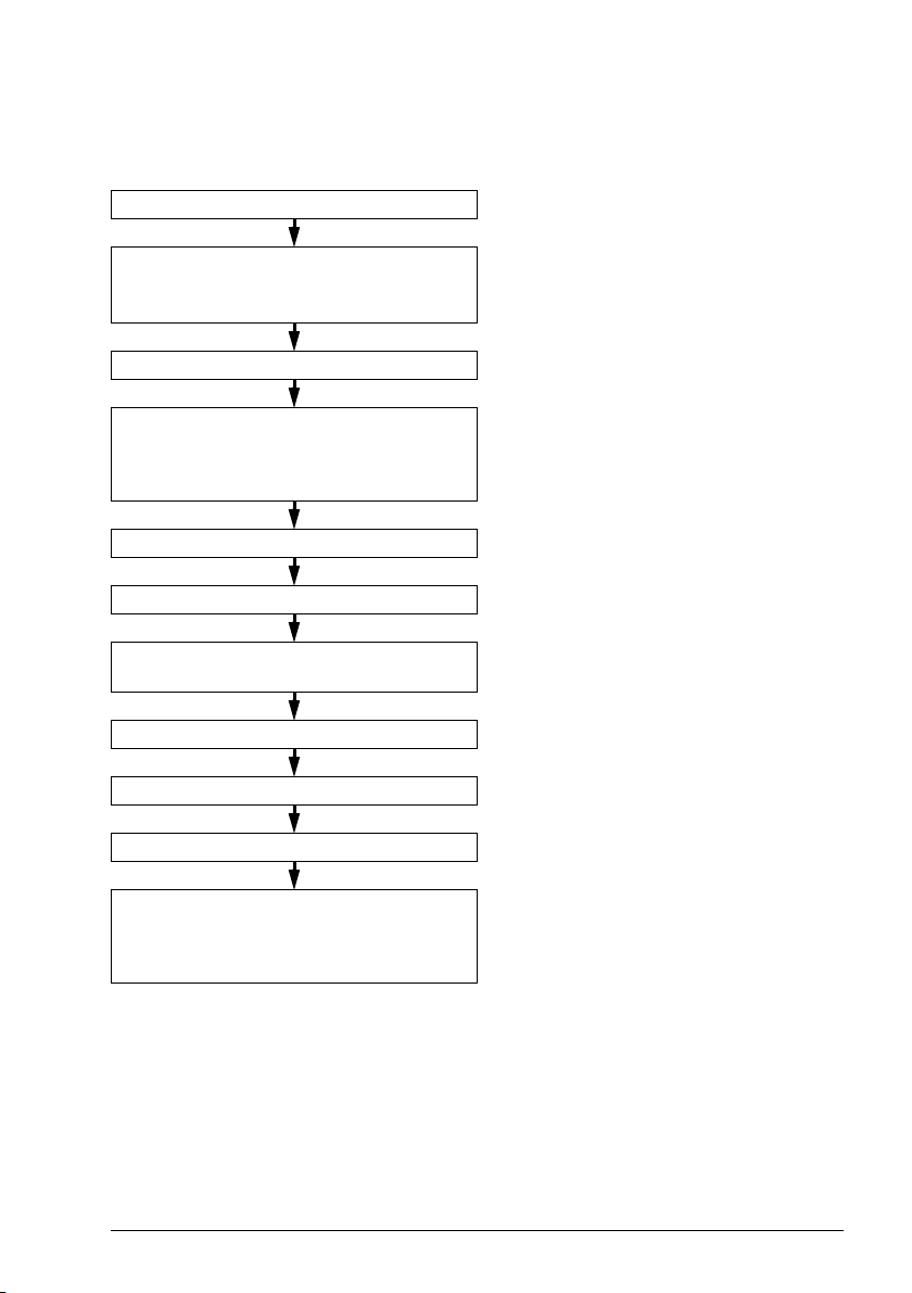
Quick installation and commissioning flowchart
Task Refer to
Identify the frame size: R0, R1, R2, etc. Type designation key on page 35.
Plan the installation.
Check the ambient conditions, ratings and
required cooling air flow.
Unpack and check the drive. Unpacking the delivery on page 42.
If the drive will be connected to an IT
(ungrounded) system or corner-grounded TN
system, make sure that the internal EMC filter
is not connected.
Install the drive. Installing the drive on page 43.
Route the cables. Routing the cables on page 52.
Measure the insulation of the input cable,
motor and motor cable.
Connect the power cables. Connecting the power cables on page 60.
Connect the control cables. Connecting the control cables on page 62.
Examine the installation. Installation checklist on page 71.
Planning the electrical installation on page 45.
Technical data on page 79.
Type designation key on page 35.
Compatibility with IT (ungrounded) and
corner-grounded TN systems on page 59.
Measuring insulation on page 58.
Commission the drive. Refer to the ACS380 Quick installation and
start-up guide (3AXD50000018553 [English])
and the ACS380 Firmware manual
(3AXD50000029275 [English]).

24 Introduction to the manual
Terms and abbreviations
Term/abbreviation Explanation
ACS-AP-X Assistant control panel. An advanced operator keypad for
Brake chopper Conducts the surplus energy from the intermediate circuit of the drive to
Brake resistor Dissipates the drive surplus braking energy conducted by the brake
Capacitor bank Refer to DC link capacitors.
Control board Circuit board in which the control program runs.
BAPO-01 Optional side-mounted auxiliary power extension module
BCAN-11 Optional CANopen interface
BCBL-01 Optional USB to RJ45 cable
BREL-01 Optional side-mounted relay output extension module
BTAC-02 Optional side-mounted pulse encoder interface module
CCA-01 Optional cold configuration adapter
DC link DC circuit between rectifier and inverter
DC link capacitors Energy storage which stabilizes the intermediate circuit DC voltage
Drive Frequency converter for controlling AC motors
EFB Embedded fieldbus
EMC Electromagnetic compatibility
FBA Fieldbus adapter
FCAN-01/-01-M Optional CANopen adapter module
FCNA-01 Optional ControlNet adapter module
FDNA-01 Optional DeviceNet adapter module
FECA-01/-01-M Optional EtherCAT adapter module
FENA-11/-21/
-21-M
FEPL-02 Optional Ethernet POWERLINK adapter module
FPBA-01/-01-M Optional PROFIBUS DP adapter module
Frame (size) Refers to drive physical size, for example, R0 and R1. The type
I/O Input/Output
IGBT Insulated gate bipolar transistor
Intermediate circuit Refer to DC link.
Inverter Converts direct current and voltage to alternating current and voltage.
LRFI Series of optional EMC filters
communication with the drive.
the brake resistor when necessary. The chopper operates when the DC
link voltage exceeds a certain maximum limit. The voltage rise is
typically caused by deceleration (braking) of a high inertia motor.
chopper to heat. Essential part of the brake circuit. Refer to Brake
chopper.
Optional Ethernet adapter module for EtherNet/IP, Modbus TCP and
PROFINET IO protocols
designation label attached to the drive shows the frame of the drive,
refer to Type designation key on page 35.

Introduction to the manual 25
Term/abbreviation Explanation
LSW Least significant word
Macro Pre-defined default values of parameters in drive control program. Each
macro is intended for a specific application.
NETA-21 Optional remote monitoring tool
Network control With fieldbus protocols based on the Common Industrial Protocol
Parameter User-adjustable operation instruction to the drive, or signal measured or
PLC Programmable logic controller
PROFIBUS,
PROFIBUS DP,
PROFINET IO
R0, R1, … Frame (size)
RCD Residual current device
Rectifier Converts alternating current and voltage to direct current and voltage.
RFI Radio-frequency interference
SIL Safety integrity level. Refer to Safe torque off function on page 121.
STO Safe torque off. Refer to Safe torque off function on page 121.
TM
), such as DeviceNet and Ethernet/IP, denotes the control of the
(CIP
drive using the Net Ctrl and Net Ref objects of the ODVA AC/DC Drive
Profile. For more information, refer to www.odva.org, and the following
manuals:
• FDNA-01 DeviceNet adapter module user’s manual (3AFE68573360
[English])
• FENA-01/-11/-21 Ethernet adapter module user’s manual
(3AUA0000093568 [English])
calculated by the drive
Registered trademarks of PI - PROFIBUS & PROFINET International

26 Introduction to the manual

Hardware description 27
3
Hardware description
Contents of this chapter
This chapter describes the operation principle, layout, type designation label and type
designation information. It shows a general diagram of the power connections and
control interfaces.
General description
The ACS380 is a drive for controlling asynchronous AC induction motors, permanent
magnet synchronous motors and ABB synchronous reluctance motors (SynRM
motors). It is optimized for cabinet mounting.
Product variants
The drive has three primary product variants:
• Standard variant (ACS380-04xS) with extended I/O & Modbus module
• Configured variant (ACS380-04xC) for which the extension module, such as the
preconfigured fieldbus adapter, is chosen when ordering.
• Base variant (ACS380-04xN) without preinstalled extension modules
Refer to Type designation key on page 35.
28 Hardware description
1
2
3
4
5
6
7
9
11
12
13
15
16
10
8
14
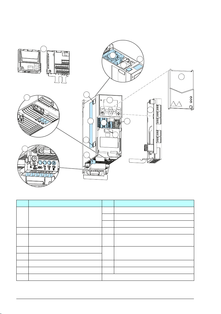
Hardware overview
Item Description Item Description
1 Front option modules (I/O and
Modbus or Fieldbus module
depending on the variant)
2 Input power connection terminal 12 Fixed control terminals
3 Motor and braking resistor connection
terminal
4 Cooling fan 14 Cold configuration connection for
5 Panel and PC tool port (RJ45)
6 Model information label 15 Option slot 2 for side-mounted options
7 EMC filter grounding screw 16 Front cover
8 Type designation label
9 Varistor grounding screw
10 PE connection (motor)
11 Control panel, display and status LED
13 Option slot 1 for communication modules
(I/O or Fieldbus modules)
CCA-01
Hardware description 29
RC
RA
RB
+24V DGND DCOM SGND S+
DI1
DI2
S1
S2
DI 3
DIO SRC
DIO COM
AI 1
AGND
SCR
+10V
DI 4
DIO 1
DIO 2
AI 2
AGNDAOAGND
B+A-BGND
Shield
6 7
8
1
2
3
4
5
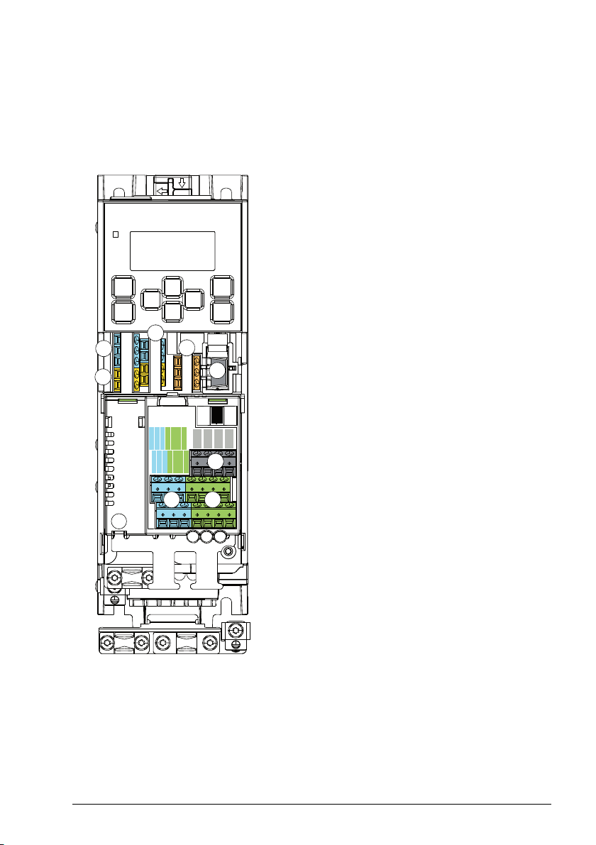
Control connections
In addition to the fixed control connections in the base unit, the other control
connections depend on the drive variant.
Standard variant (I/O and Modbus) (ACS380-04xS)
The standard variant has a type code as
follows: ACS380-04xS. Refer to Type
designation key on page 35.
Connections:
1. Auxiliary voltage outputs
2. Digital inputs
3. Safe torque-off connections
4. Relay output connection
5. Cold configuration connection for CCA-01
6. Digital inputs and outputs
7. Analog inputs and outputs
8. EIA-485 Modbus RTU
30 Hardware description
RC
RA
RB
+24V DGND DCOM SGND S+
DI1
DI2
S1
S2
HOST
CHASSIS
MODULE
LINK
NETWORK
X1
6
1
3
2
4
5
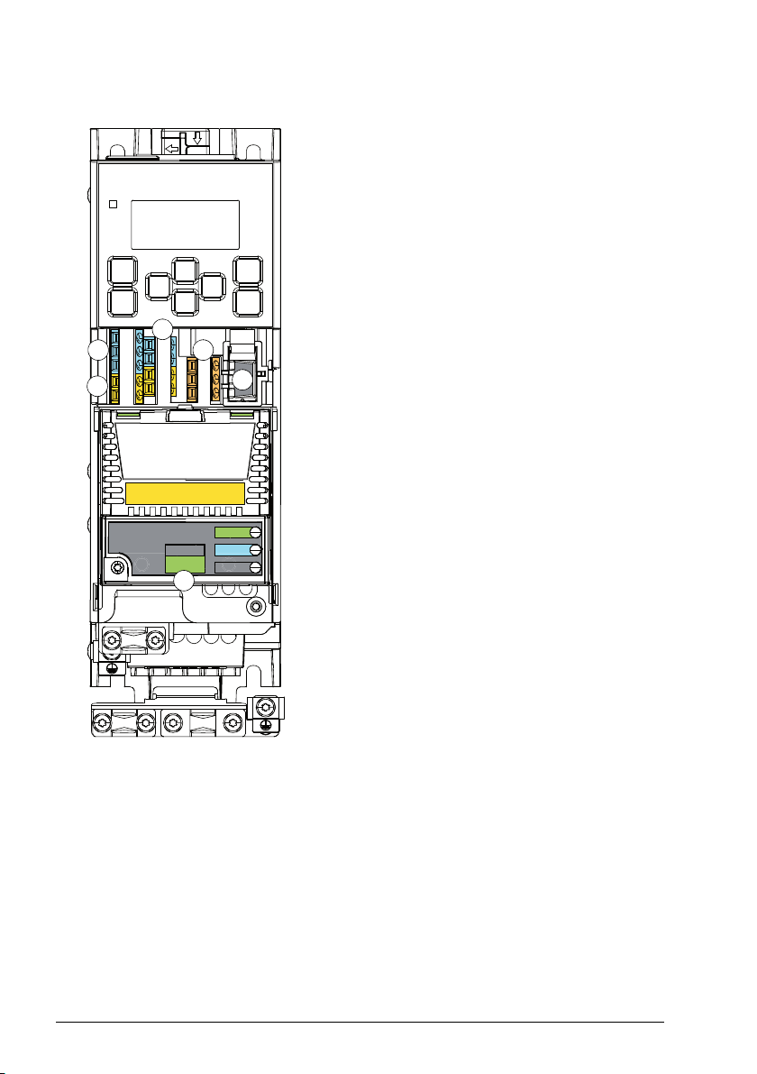
Configured variant (ACS380-04xC)
The configured variant has a type code as
follows: ACS380-04xC followed by an option
code that designates the extension module.
Use the configured variant to order a product
with a specific fieldbus extension module.
Refer to Type designation key on page 35.
Connections:
1. Auxiliary voltage outputs
2. Digital inputs
3. Safe torque-off connections
4. Relay output connection
5. Cold configuration connection for CCA-01
6. Fieldbus connections depending on the
module
 Loading...