

ABB AC31 Assembly And Operation Manual
ASSEMBLY AND OPERATION MANUAL
AC31 Adapter
Supplement to the Existing Documentation

Table of contents
—
Table of contents
1 AC31 Adapters................................................................................................................................................. 3
1.1 Introduction................................................................................................................................................ 3
1.2 Overview of AC31 adapters (replacement devices).................................................................................. 3
1.3 System data and CS31 bus system data.................................................................................................. 4
1.3.1 System data of the AC31 adapters............................................................................................ 4
1.3.2 CS31 bus system data............................................................................................................. 10
1.4 Replacement devices: CPU.................................................................................................................... 18
1.4.1 Replacement device 07KT9x-AD............................................................................................. 19
1.5 Replacement devices: I/O modules......................................................................................................... 56
1.5.1 Replacement device 07DC91-AD............................................................................................ 57
1.5.2 Replacement device 07DC92-AD............................................................................................ 72
1.5.3 Replacement device 07AI91-AD.............................................................................................. 88
1.5.4 Replacement device 07AC91-AD.......................................................................................... 107
1.5.5 Replacement device 07AC91-AD2........................................................................................ 121
1.5.6 Replacement unit DC501-CS31-AD....................................................................................... 137
2 Index............................................................................................................................................................. 161
2018/09/243ADR010122, 8, en_US2
—
AC31 Adapters
Overview of AC31 adapters (replacement devices)
1 AC31 Adapters
1.1 Introduction
Replacement
devices for
AC31
Note regarding
product documentation
The modular product line of the AC31 adapter series includes modular exchange components
for control systems of the Advant Controller 31 (90 series). The simple exchange of individual
components allows existing customers to maintain their PLCs in a quick and cost-effective
manner. Extensive software modifications are not required.
Each replacement device is based on trend setting technologies of the AC500 series. Therefore, by exchanging components it is not only possible to replace the existing device, but also to
profit from new functions and improved product quality.
During the development of the AC31 adapter series, care was taken to keep the device configuration identical to the configuration of the AC31 devices. Consequently, the technical documents
for the AC31 devices are still valid and serve as reference:
● Software description (only available in English)
● System description Advant Controller 31
Only unavoidable deviations, for example due to technical limitations, are described in this
document.
CAUTION!
Installation and maintenance work on the device must be performed by a qualified electrician in line with the recognized technical rules, regulations and relevant standards such as EN 60204-1.
For safety instructions, please refer to
Regulations for the erection of installations.
1.2 Overview of AC31 adapters (replacement devices)
An AC31 adapter (replacement device) is available for the following AC31 devices of the 90
series (existing devices):
Existing devices: AC31
(90 series)
CPU devices:
07KT94-ARC
07KT98-ARC
07KT98-ARC-DP
07KT98-ARC-ETH
07KT98-ETH-DP
--
Replacement devices: AC31
adapters
07KT94-ARC-AD *)
07KT98-ARC-AD
07KT98-ARC-DP-AD
07KT98-ARC-ETH-AD
07KT98-ETH-DP-AD
07KT98-ARC-ETH-DP-AD
Replacement device is based
on the following AC500
device
PM590, DA501 and DA502
*
) Customer specific product not available for current sales
2018/09/24 3ADR010122, 8, en_US 3
AC31 Adapters
System data and CS31 bus system data > System data of the AC31 adapters
Existing devices: AC31
(90 series)
I/O modules:
07DC91 07DC91-AD DC532
07DC92 07DC92-AD DO524
07AC91 07AC91-AD (8-Bit) AO523
07AC91 07AC91-AD2 (12-Bit) AX522
07AI91 07AI91-AD AI523
DC501-CS31 DC501-CS31-AD DC532
Replacement devices: AC31
adapters
1.3 System data and CS31 bus system data
The system data described in this chapter are valid for the following replacement devices:
● 07KT94-ARC-AD
● 07KT98-ARC-AD
● 07KT98-ARC-DP-AD
● 07KT98-ARC-ETH-AD
● 07KT98-ETH-DP-AD
● 07KT98-ARC-ETH-DP-AD
● 07AC91-AD
● 07AC91-AD2
● 07AI91-AD
● 07DC91-AD
● 07DC92-AD
● DC501-CS31-AD
Replacement device is based
on the following AC500
device
Please also observe the CS31 bus system data Ä Chapter 1.3.2 “CS31 bus system data”
on page 10.
The devices of the AC31 adapter series do not have marine approval.
NOTICE!
AC31 Adapter IO modules must only be used with an ABB CPU with Master
CS31 bus (e.g. AC31 07KT9x, AC31-Adpater 07KT9x-x-x-AD or AC500 CPU).
1.3.1 System data of the AC31 adapters
1.3.1.1 Operating and environmental conditions
Table 1: Supply voltages
Voltages according to IEC 61131-2:
24 V DC Process and supply voltage 24 V DC (-15 %, +20 %
Absolute limits 19.2 V ... 30 V incl. residual
without residual ripple)
ripple
2018/09/243ADR010122, 8, en_US4

Residual ripple £ 5 %
AC31 Adapters
System data and CS31 bus system data > System data of the AC31 adapters
Polarity reversal protection 10 s (test duration), perma-
nently present on AC31
adapters
Bridging time for power interruptions according to IEC 61131-2:
DC supply Interruption < 10 ms
Time between 2 interruptions
> 1 s
CAUTION!
System damage caused by voltage!
Exceeding the maximum supply or process voltage (>30 V DC) results in permanent system damage (destruction).
Table 2: Operating and environmental conditions
Temperature:
-> Operation 0 °C ... +55 °C (vertical mounting position, ter-
-> Storage -40 °C ... +75 °C
-> Transport -40 °C ... +75 °C
Humidity max. 95 %, without condensation
Air pressure:
-> Operation > 800 hPa / < 2000 m
-> Storage > 660 hPa / < 3500 m
1.3.1.2 Creepage distances and clearances
The creepage distances and clearances correspond to overvoltage category II, pollution degree
2.
1.3.1.3 Test voltages for type test
Test voltages for type test according to IEC 61131-2:
Table 3: Impulse testing
Data Voltage Duration
minals upward and downward)
24 V circuits (supply, 24 V inputs/outputs), when electri-
500 V 1.2 / 50 µs
cally isolated from other circuitry
CS31 interface from other circuitry 500 V 1.2 / 50 µs
Ethernet 500 V 1.2 / 50 µs
ARCNET 500 V 1.2 / 50 µs
COM interfaces, electrically isolated 500 V 1.2 / 50 µs
Enabling input, electrically isolated 500 V 1.2 / 50 µs
2018/09/24 3ADR010122, 8, en_US 5

AC31 Adapters
System data and CS31 bus system data > System data of the AC31 adapters
Table 4: AC voltage tests
Data Voltage Duration
24 V circuits (supply, 24 V inputs/outputs), when electrically isolated from other circuitry
CS31 interface from other circuitry 350 VAC 60 s
Ethernet 350 VAC 60 s
ARCNET 350 VAC 60 s
COM interfaces, electrically isolated 350 VAC 60 s
Enabling input, electrically isolated 350 VAC 60 s
1.3.1.4 Power Supply Units
For the supply of devices, use power supply units according to PELV specification.
1.3.1.5 Electromagnetic compatibility
Table 5: Immunity
Data Value
Immunity against electrostatic discharge
(ESD)
350 VAC 60 s
According to EN 61000-4-2, zone B, criterion
B
-> Interference voltage with air discharge 8 kV
-> Interference voltage with contact discharge 4 kV
ESD with communication connectors Ensure that any electrostatic charge is dis-
charged prior to contact with the communication connectors (e.g. by touching an earthed
metal object). Otherwise malfunctions may
occur.
ESD module carrier connectors Do not touch the plug connecting the module
carrier on the bottom side of the device.
ESD external coupler interface Do not touch the plug to the flat ribbon cable.
Immunity against the influence of radiated
interference (CW radiated)
According to EN 61000-4-3, zone B, criterion
A
-> Test field strength 10 V/m (except ITU transmission bands 87…
108 MHz, 174…230 MHz and 470…790 MHz
-> 3 V/m)
-> Maximum temporary deviation during irradi-
ation
Analog current output signals max. 1.5 %.
Devices affected:
07AC91-AD, 07AC91-AD2,
07KT94-ARC-AD, 07KT98-ARC-AD,
07KT98-ARC-DP-AD, 07KT98-ARC-ETH-AD,
07KT98-ETH-DP-AD, 07KT98-ARC-ETH-DPAD
Immunity against transient interference voltages (burst)
-> Voltage supply 2 kV
-> Enabling input 2 kV
According to EN 61000-4-4, zone B, criterion
B
2018/09/243ADR010122, 8, en_US6
Data Value
AC31 Adapters
System data and CS31 bus system data > System data of the AC31 adapters
-> Digital inputs/outputs 1 kV
-> Analog inputs/outputs 1 kV
-> CS31 system bus 1 kV
-> Serial RS-232 interfaces (COM) 1 kV
-> ARCNET 1 kV
-> Ethernet 1 kV
-> I/O supply, DC out 1 kV
Immunity against the influence of power
related interference (CW radiated):
According to EN 61000-4-6, zone B, criterion
A
-> Test voltage Zone B, also according to 10 V
Immunity against transient interference voltages with high energy (surge)
According to EN 61000-4-5, zone B, criterion
B
-> Voltage supply DC, enabling input 0.5 kV CM / 0.5 kV DM *)
-> I/O supply, DC out 0.5 kV CM / 0.5 kV DM *)
-> Shielded buses 1 kV CM *)
-> I/O analog, I/O DC unshielded 1 kV CM / 0.5 kV DM *)
Emitted interference (radiation): -
-> From radiated interferences According to EN 55011, group 1, class A
*) CM = Common Mode, DM = Differential Mode
The devices of the AC31 adapter series do not have marine approval.
1.3.1.6 Mechanical data
Data Value
Degree of protection IP20
Housing According to UL 94
Vibration resistance according to EN 61131-2 All three axes
Vibration resistance with SD card plugged 15 Hz ... 150 Hz, continuous 1 g
Shock resistance All three axes
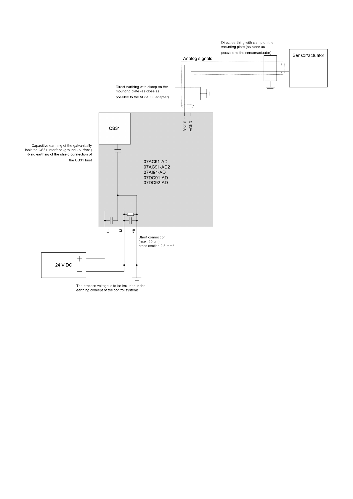
1.3.1.7 Earthing
The AC31 adapter devices can be earthed as follows:
2 Hz ... 15 Hz, continuous 3.5 mm
15 Hz ... 150 Hz, continuous 1 g
15 g, 11 ms, semi-sinusoidal
2018/09/24 3ADR010122, 8, en_US 7
AC31 Adapters
System data and CS31 bus system data > System data of the AC31 adapters
Fig. 1: Earthing of devices 07AC91-AD, 07AC91-AD2, 07AI91-AD, 07DC91-AD and 07DC92-AD
2018/09/243ADR010122, 8, en_US8
AC31 Adapters
System data and CS31 bus system data > System data of the AC31 adapters
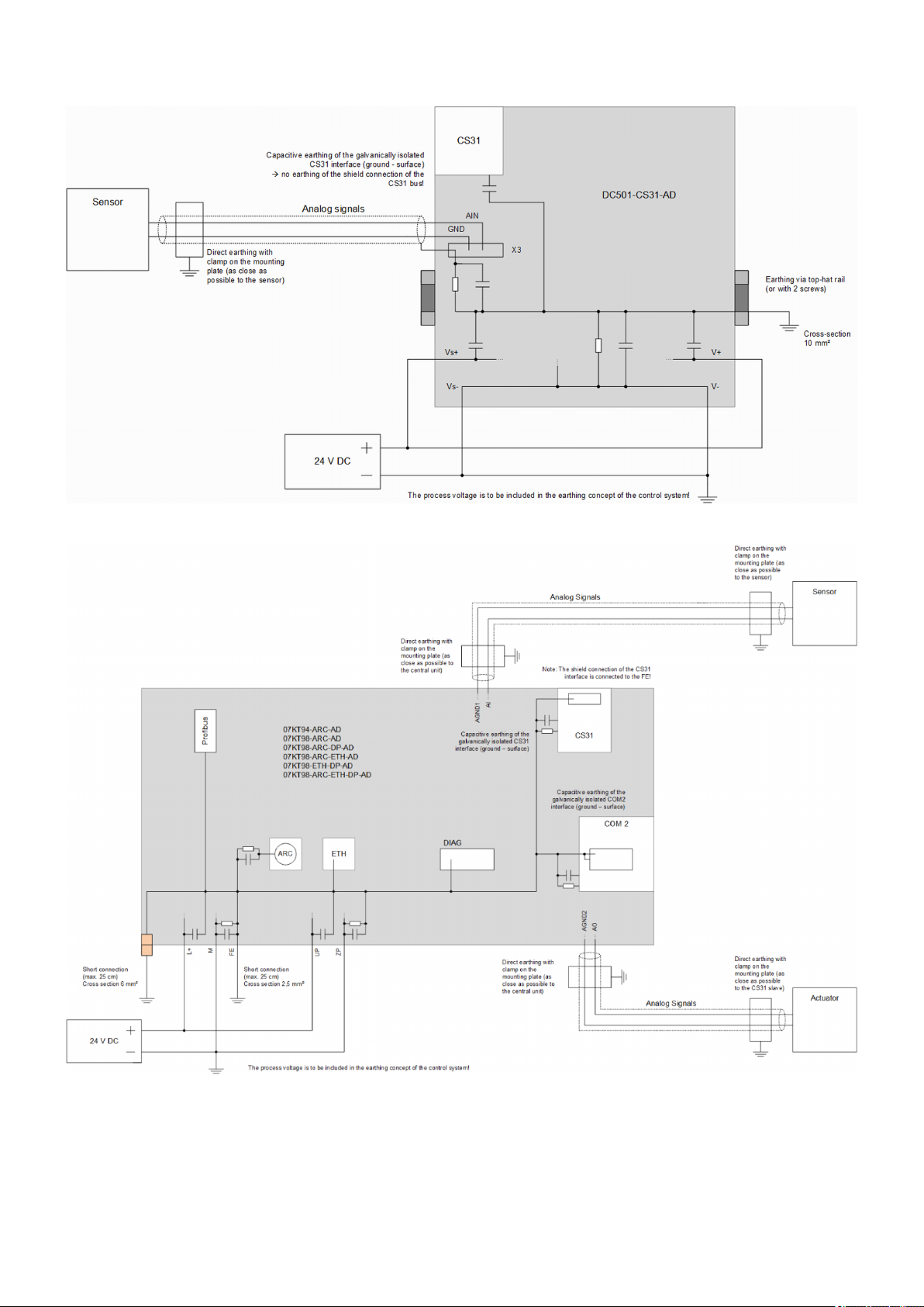
Fig. 2: Earthing of device DC501-CS31-AD
Fig. 3: CPU earthing
When earthing the replacement devices, observe the following:
● Install the AC31 adapter devices onto an earthed mounting plate to ensure a uniform reference potential of all equipment.
● Implement the connections between switchgear cabinet, mounting plate, PE rail and shield
rail with low impedance.
2018/09/24 3ADR010122, 8, en_US 9
AC31 Adapters
System data and CS31 bus system data > CS31 bus system data
● Install the lines in groups (power lines, power supply lines, signal lines, data lines).
● Use lines with braided cable shield for analog signals. Earth the shield on both sides and
make sure that no compensation currents flow through the cable shield. For this purpose,
use a potential equalization line with current carrying capacity, for instance on systems consisting of several switchgear cabinets.
Further information concerning CS31 bus earthing:
1.3.2 CS31 bus system data
1.3.2.1 Wiring
Table 6: Bus line
Data Value
Configuration 2 cores, twisted, with common shield
Cross section > 0.22 mm² (24 AWG)
Recommendation: 0.5 mm² corresponds to Ø
0.8 mm
Twisting rate > 10/m (symmetrically twisted)
Core insulation Polyethylene (PE)
Resistance per core < 100 Ω/km
Characteristic impedance approx. 120 Ω (100 ... 150 Ω)
Capacitance between the cores < 55 nF/km (in case of higher capacitance
values, the maximum possible bus length is
reduced)
Terminating resistors 120 Ω ¼ W at both ends
Notes Cables with PVC core insulation and core
diameter of 0.8 mm can be used up to a
length of approx. 250 m. In this case, the terminating resistor is 100 Ω. Cables with PE
core insulation can be used up to a length of
approx. 500 m.
The baud rate used on the CS31 bus is 187.5 kBaud.
1.3.2.2 Bus topology
A CS31 system bus always contains only one CS31 bus master to control the bus. Up to 31
CS31 slaves can be controlled by one bus. The CS31 bus master has no address, whereas the
CS31 slaves can accept addresses in the range from 0 - 61, depending on CS31 slave type.
Possible CS31 bus masters:
● 07KT94-ARC-AD, 07KT94
● 07KT98-ARC-AD, 07KT98
● 07KT98-ARC-DP-AD
● 07KT98-ARC-ETH-AD
● 07KT98-ETH-DP-AD
● 07KT98-ARC-ETH-DP-AD
2018/09/243ADR010122, 8, en_US10
Possible CS31 slaves:
AC31 Adapters
System data and CS31 bus system data > CS31 bus system data
● 07AC91-AD, 07AC91
● 07AC91-AD2
● 07AI91-AD, 07AI91
● 07DC91-AD, 07DC91
● 07DC92-AD, 07DC92
● DC501-CS31-AD, DC501-CS31
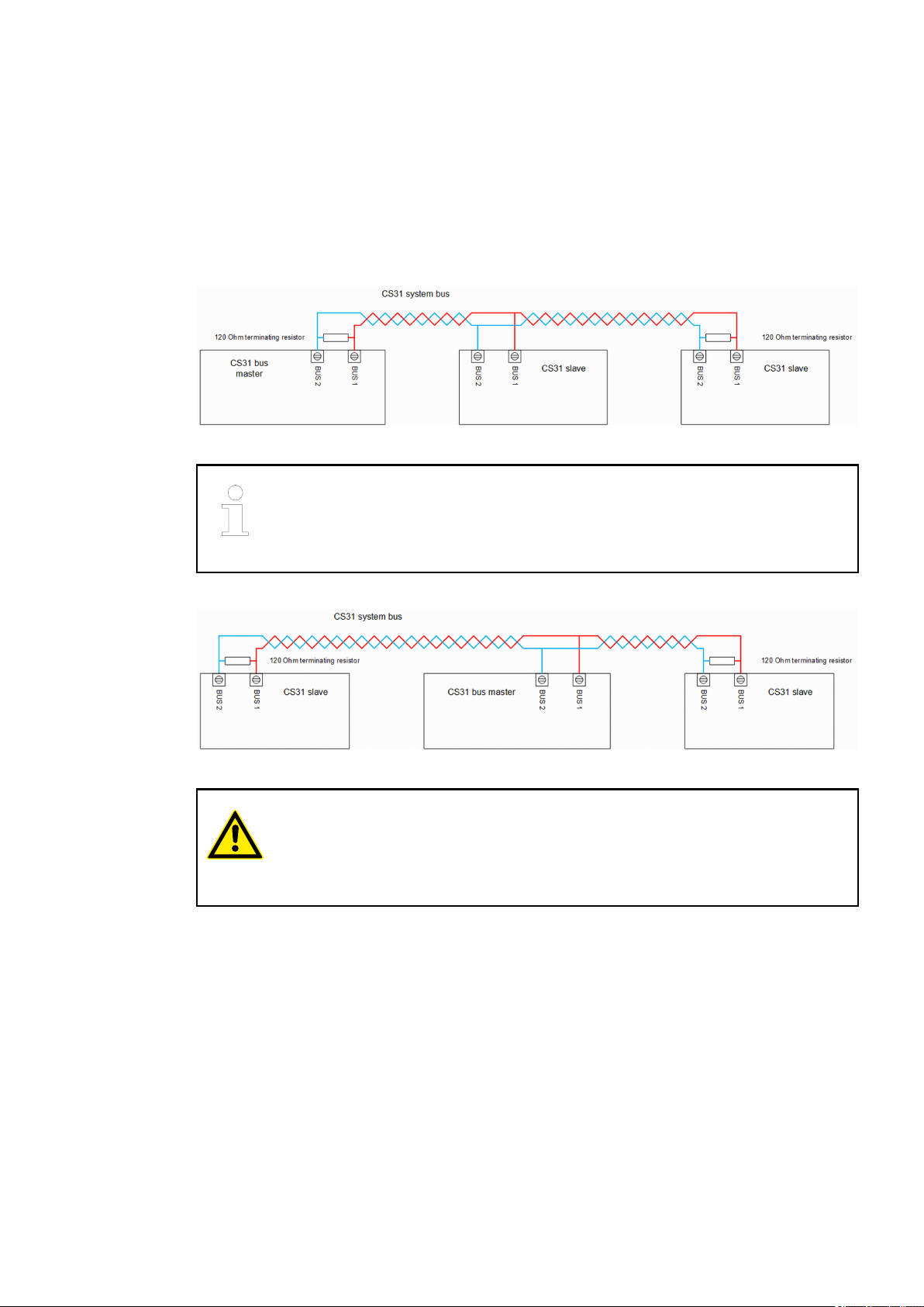
The following diagram shows the bus topology without shielding and earthing treatment:
Fig. 4: Bus topology with CS31 bus master on the side
The CS31 slave DC501-CS31-AD has an internal 120 Ω terminating resistor
which can be connected by using a DIP switch. On the other CS31 slaves and
the CS31 bus master, the terminating resistor must be installed externally by the
user.
The following diagram shows the bus topology without shielding and earthing treatment:
Fig. 5: Bus topology with CS31 bus master in the middle
CAUTION!
Risk of malfunctions!
Spur lines are not allowed within the CS31 bus. Loop the bus line from module
to module.
Correct cable laying:CS31 cable
laying
2018/09/24 3ADR010122, 8, en_US 11
AC31 Adapters
System data and CS31 bus system data > CS31 bus system data
Incorrect cable laying:
1.3.2.3 Earthing
Current carrying
capacity
In order to avoid disturbances, earth the cable shields directly.
Choose direct earthing if it can be ensured by means of current carrying metal connections
(steel constructions, earth bars, etc.) that no potential differences can occur.
2018/09/243ADR010122, 8, en_US12
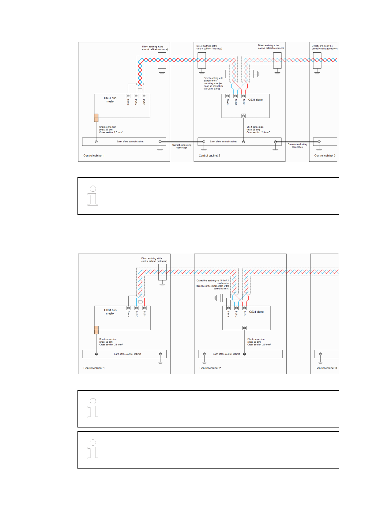
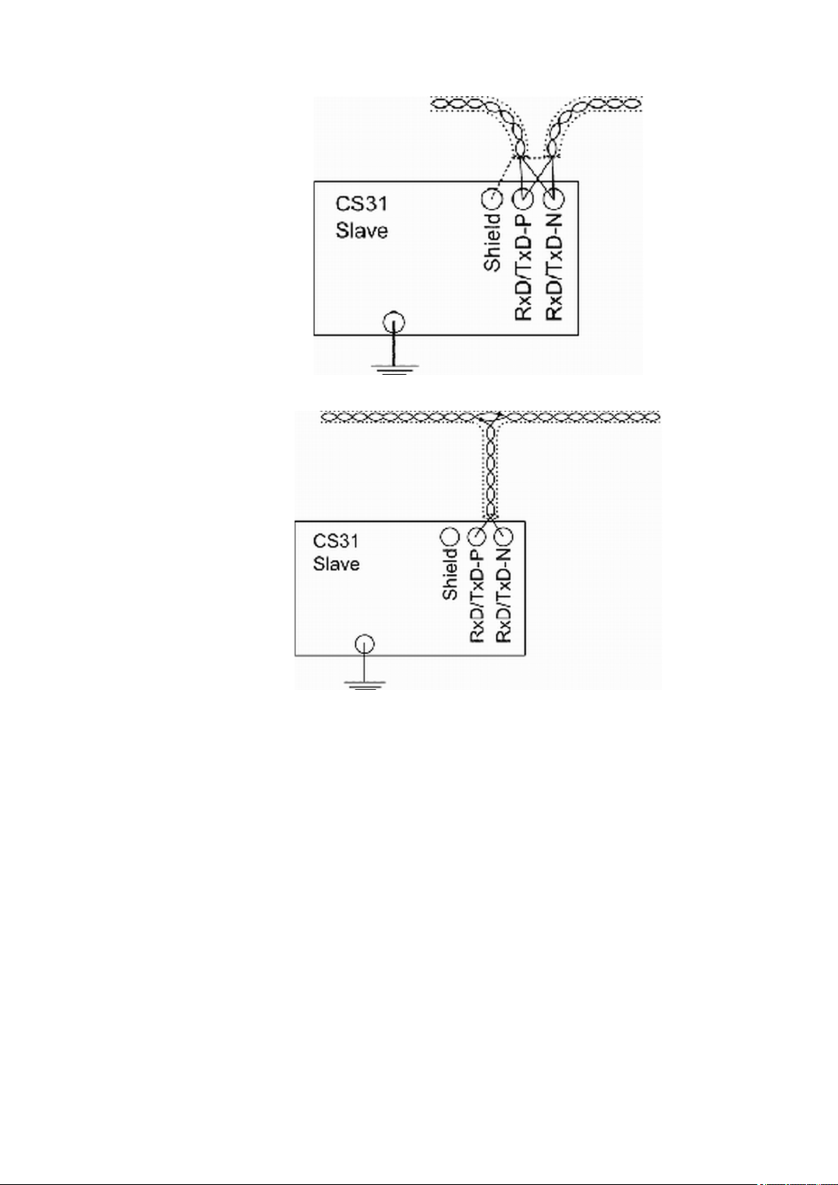
Fig. 6: Direct earthing of CS31 bus master and CS31 slave
AC31 Adapters
System data and CS31 bus system data > CS31 bus system data
No current carrying capacity
The shield connection of the CS31 bus master is internally connected to the
earth terminal.
Apply capacitative earthing if system parts are not connected to each other in terms of their current carrying capacity. This prevents the flow of compensation currents through the cable
shields.
Fig. 7: Direct earthing of CS31 bus master and capacitative CS31 slave
On the CS31 slave, the shield connection is not connected internally and thus
not earthed. The shield connection can be used to connect the shields of two
cables.
VDE 0160 requires that the system's shield is earthed directly at least once.
2018/09/24 3ADR010122, 8, en_US 13
AC31 Adapters
System data and CS31 bus system data > CS31 bus system data
1.3.2.4 Bus cycle time and data security
The communication via the CS31 bus is cyclic and controlled by the CS31 bus master.
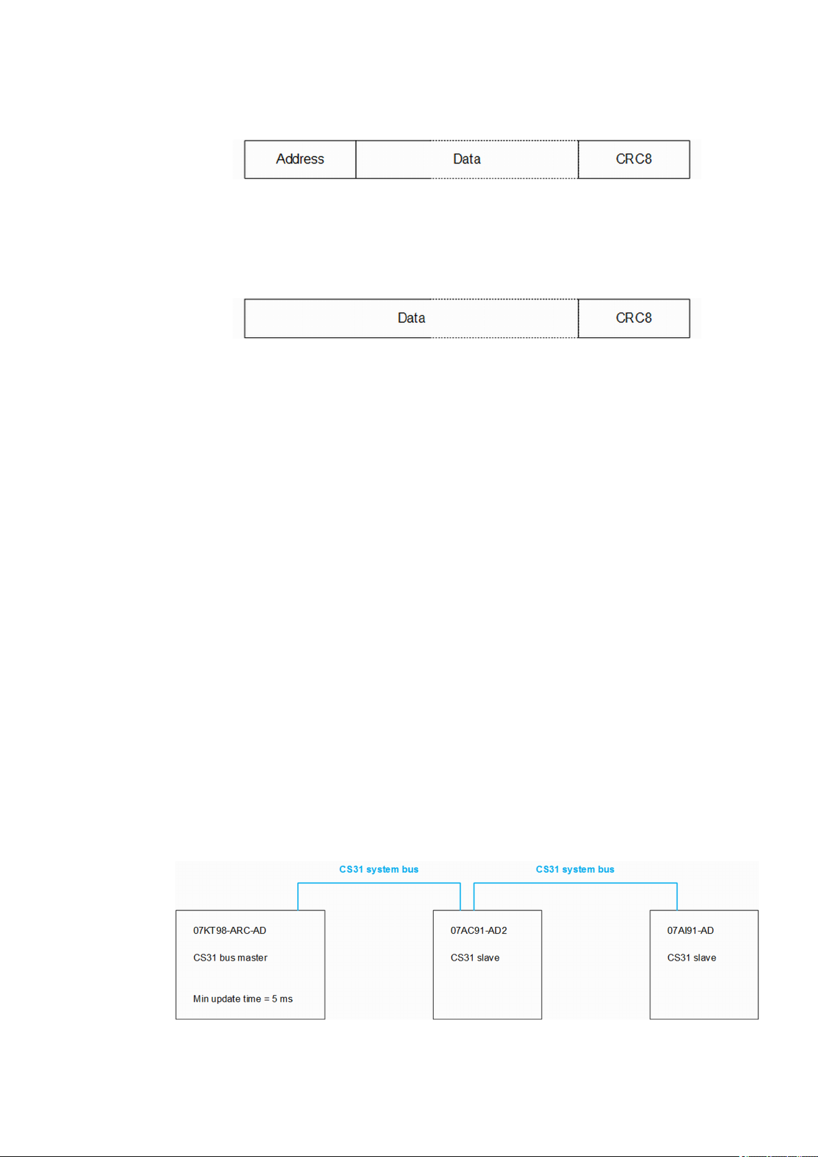
Fig. 8: Format of request telegram of a CS31 bus master
In each cycle, the CS31 bus master successively polls all existing CS31 slaves at regular intervals, performs a diagnosis on one of the existing CS31 slaves and sends a request to search for
added CS31 slaves. Thus, on one hand it is possible to maintain a continuous diagnosis of the
proper network function and on the other hand to take all the newly added CS31 slaves into
account.
Fig. 9: Format of response telegram of a CS31 slave
The CS31 slaves respond to the telegrams of the CS31 bus master with a response telegram
(see diagram above). The data are indicated in the documentation of the individual devices (e.g.
07AC91-AD2). The telegram is ignored when a CS31 slave or a CS31 bus master detects a
deviation between the received CRC and the self-calculated CRC. A CS31 bus error exists
when 10 faulty telegrams are issued successively.
The bus cycle time is composed of a base time, the bus transmission times of the data of the
individual CS31 slaves and the bus idle times between the individual telegrams.
During the base time, the CS31 bus master performs a diagnosis and searches for newly added
CS31 slaves. This time depends on the control system (PLC / central unit) and is partially configurable:
● Devices 07KT94 and 07KT98: base time 2 ms
● Device 07KT94-ARC-AD: base time 10 ms *)
● Devices 07KT98-ARC-AD, 07KT98-ARC-DP-AD, 07KT98-ARC-ETH-AD, 07KT98-ETH-DPAD,
07KT98-ARC-ETH-DP-AD:
Base time 5 ms to 100 ms (configurable in Automation Builder, parameter "Min update
time")
*) The base time of device 07KT94-ARC-AD cannot be configured since the old programming
environment (907 PC 331) must be used.
The bus transmission times of the data of the individual CS31 slaves can be determined as follows:
● Duration for the transmission of 1 byte = (1/187.5 kBaud) x 8 = 43 µs
● Determine number of data bytes (sending + receiving) from existing documentation
● Add 3 bytes for the transmission of the address and CRCs
Per CS31 slave, approx. 0.5 ms can be assumed as bus idle time. The CS31 bus master needs
this time to process the data. This time depends on the computing power and on the implementation of the CS31 bus master. This time can vary between various firmware versions.
Fig. 10: Example bus cycle time
2018/09/243ADR010122, 8, en_US14
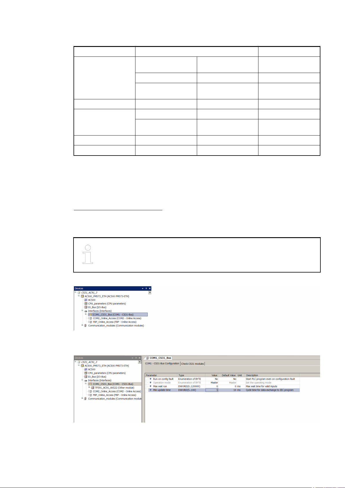
Table 7: Example: Bus cycle time
AC31 Adapters
System data and CS31 bus system data > CS31 bus system data
Base time Min. update time = 5 ms 5000 µs
Bus transmission time
07AC91-AD2
Bus idle time - - 500 µs
Bus transmission time
07AI91-AD
Bus idle time - - 500 µs
Bus cycle time (sum) - - 8322 µs ≈ 8500 µs
1.3.2.5 Configuration
Below is a description of the configuration of the devices 07KT98-ARC-AD, 07KT98-ARC-DPAD, 07KT98-ARC-ETH-AD and 07KT98-ETH-DP-AD, 07KT98-ARC-ETH-DP-AD in the Automation Builder software. For further information on Automation Builder, please refer to the
Automation Builder documentation.
The configuration of the CS31 slaves takes place only by means of DIP switches (see existing
documentation), whereby the configuration of the CS31 bus topology is carried out in the CS31
bus master.
Receiving 16 byte
16 x 43 µs 688 µs
data
Sending 16 byte data 16 x 43 µs 688 µs
3 byte address +
3 x 43 µs 129 µs
CRCs
Sending 16 byte data 16 x 43 µs 688 µs
3 byte address +
3 x 43 µs 129 µs
CRCs
The configuration of the devices 07KT94 and 07KT94-ARC-AD is carried out
with the DOS program "907 PC 331". Further information on configuration is
available in the existing documentation.
Configure the COM1 interface as CS31 bus master:
Fig. 11: CS31 bus master
The "Min update time" parameter can also be set on the CS31 bus master:
Fig. 12: Parameter configuration
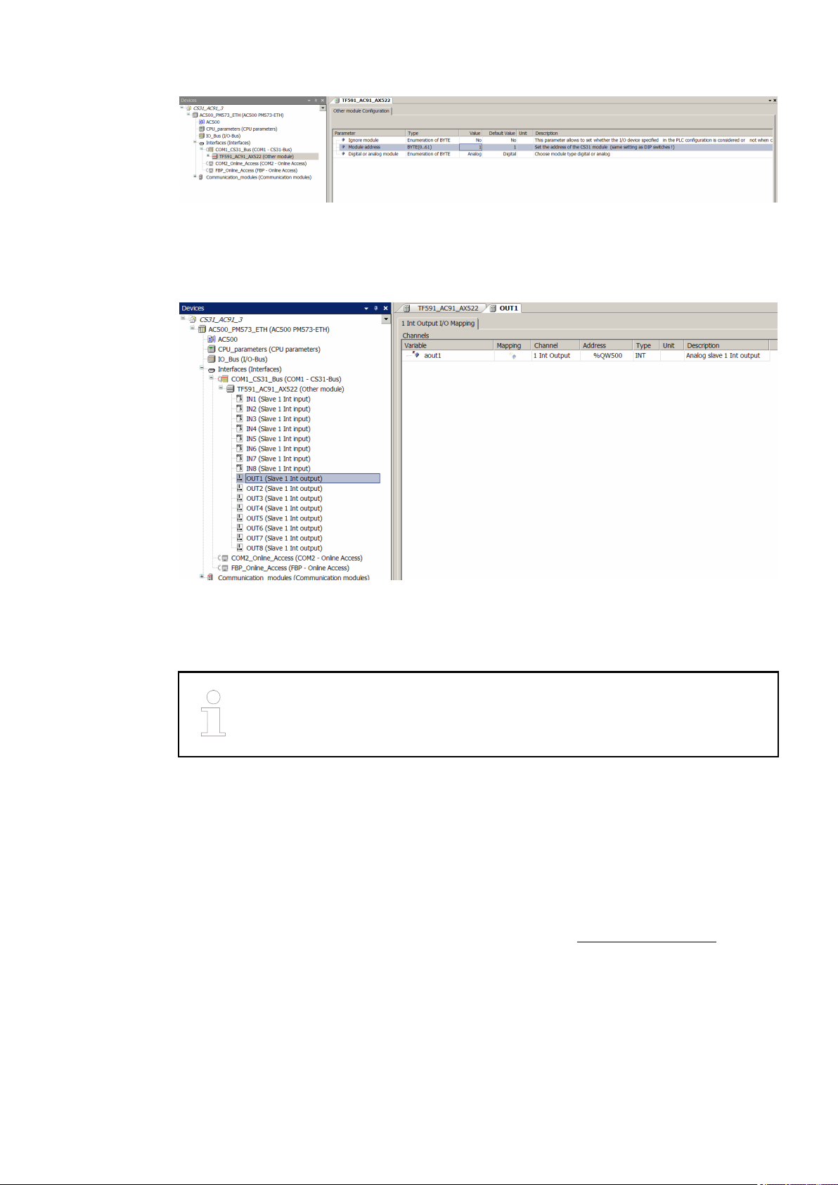
The individual CS31 slaves must be configured in the tree structure under the CS31 bus
master:
2018/09/24 3ADR010122, 8, en_US 15
AC31 Adapters
System data and CS31 bus system data > CS31 bus system data
Fig. 13: CS31 slave
The module address must be set on each CS31 slave. Specify the same module address that
has been selected with the DIP switches.
Set the CS31 slave type (analog/digital):
Fig. 14: CS31 bus slave configuration
The data must be configured in the tree structure under the CS31 bus slave. Information about
the number of input and output data can be obtained from the respective documentation of the
CS31 bus slaves.
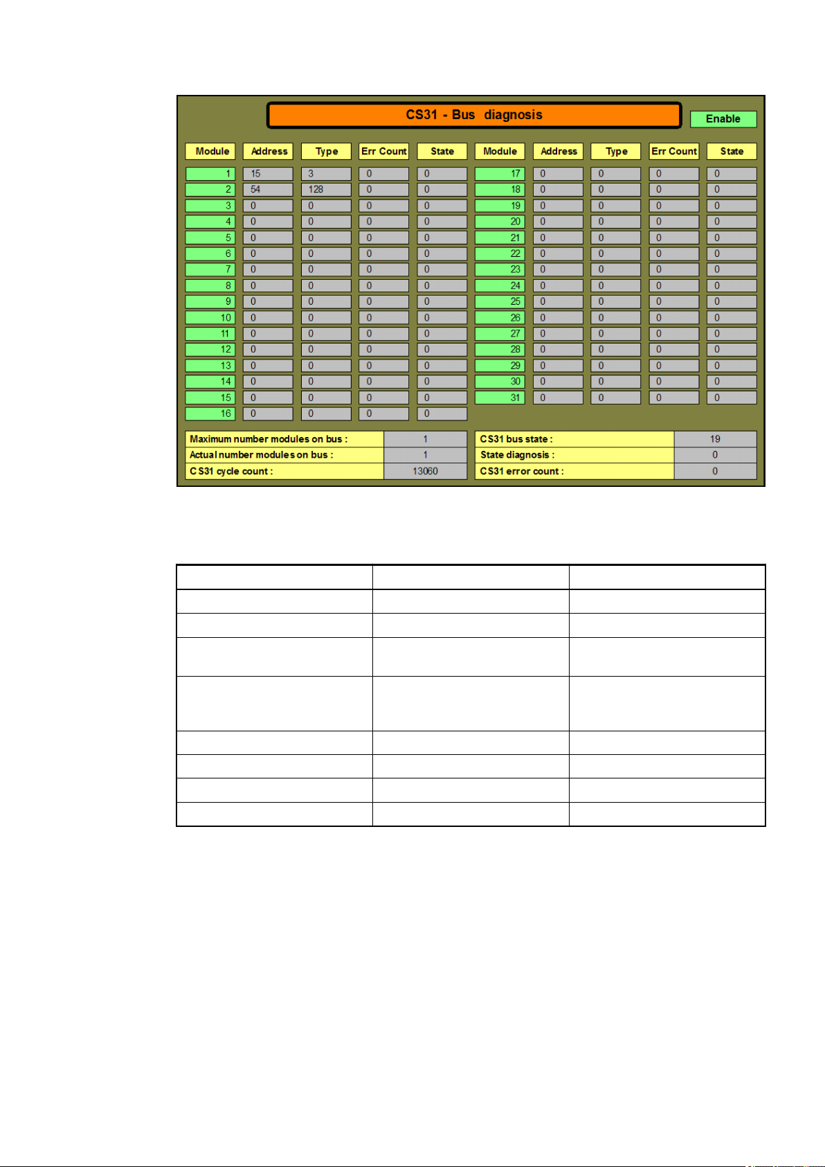
1.3.2.6 Diagnosis
For the diagnosis of the CS31 bus, various mechanisms are available in the CS31 bus master
of the devices 07KT98-ARC-AD, 07KT98-ARC-DP-AD, 07KT98-ARC-ETH-AD, 07KT98-ETHDP-AD and 07KT98-ARC-ETH-DP-AD:
● Diagnosis via the function block CS31_DIAG
● Diagnosis system of the AC500 series
For further information on both mechanisms, please refer to the AC500 documentation. Below,
only a few special diagnosis functions of the AC31 adapter are addressed.
Function block
CS31_DIAG:
In the 'State' column, the variable byStateDiag of the structure strCS31_DiagOneModule is
indicated for every CS31 bus slave.
If the data represent bipolar values (e.g. voltage from -10 V…+10 V), the use of
the data type INT is appropriate. In case of unipolar values (e.g. current from 0
mA…20 mA), the data type WORD can be used.
2018/09/243ADR010122, 8, en_US16
AC31 Adapters
System data and CS31 bus system data > CS31 bus system data
Fig. 15: Visualization: CS31 bus diagnosis
Table 8: Interpretation of variable byStateDiag
Bit Value Description
0 1 CS31 bus slave disconnected
1 2 Not used
2 4 slave on CS31 bus bus not
configured
3 8 Difference in the number of
data bytes between configuration and CS31 bus
4 16 Internal device error
5 32 Channel error
6 64 Not used
7 128 Not used
All bits of byStateDiag equal 0 -> no error in CS31 bus slave.
The variables byDiagChannel and byDiagErr in the structure strCS31_DiagOneModule
include the error channel and code. The possible values of these variables are indicated in the
documentation of the respective CS31 bus slave.
Diagnosis
The Diagnosis system of the AC500 series provides the errors in the following format:
system
2018/09/24 3ADR010122, 8, en_US 17

AC31 Adapters
Replacement devices: CPU
Table 9: Error messages AC500 series
Format e.g. name of PLC browser
command diagshow all
Error class Class 1 to 4
Faulty component Comp 11 (COM1 interface, here for
Faulty device Dev Address of CS31 bus slave
Faulty module Mod CS31 bus type of CS31 bus
Faulty channel Ch See existing documentation of
Error code Err See existing documentation of
A CS31 bus slave error is indicated by an error LED on the CS31 bus slave. The error LED
remains on even after elimination of the error and is switched off only after the error has been
acknowledged by the CS31 bus master.
The acknowledgment of a CS31 bus slave error can take place via the CS31 bus master by
means of the function block CS31QU_EXT (see AC500 documentation).
Description
the CS31 bus)
with error
slave with error (e.g. 5 for
analog input/output)
CS31 bus slave
CS31 bus slave
1.4 Replacement devices: CPU
For AC31 devices of the 90 series, AC31 adapters (replacement devices) are available for the
exchange of the CPU.
2018/09/243ADR010122, 8, en_US18
1.4.1 Replacement device 07KT9x-AD
AC31 Adapters
Replacement devices: CPU > Replacement device 07KT9x-AD
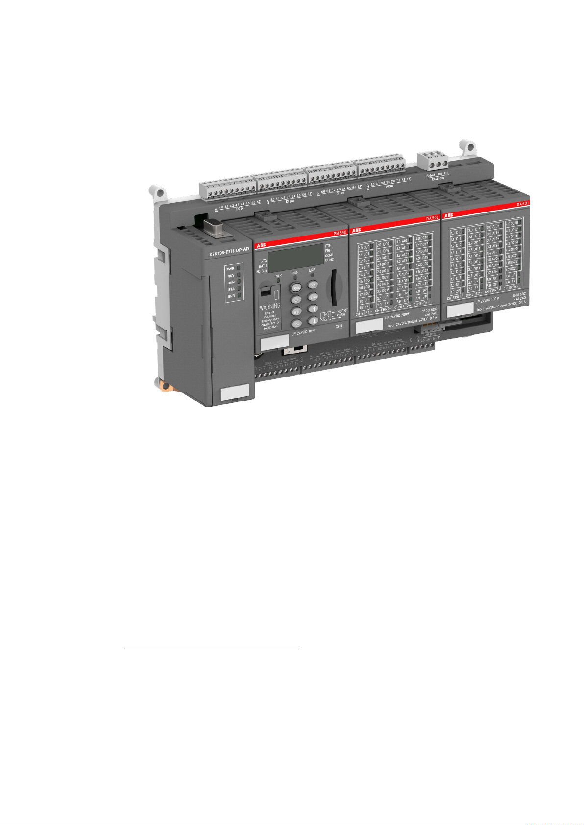
1.4.1.1 Introduction
Fig. 16: 3ADR331183S0015
The replacement device versions 07KT9x-AD of the AC31 adapter series replace the existing
devices 07KT94 and 07KT98 of the AC31 devices of the 90 series.
Versions:
● 07KT94-ARC-AD: I/O module DA501, I/O module DA502, CPU EC581 *)
● 07KT98-ARC-AD: I/O module DA501, I/O module DA502, CPU PM590-ARC
● 07KT98-ARC-DP-AD: I/O module DA501, I/O module DA502, CPU PM590-ARC
● 07KT98-ARC-ETH-AD: I/O module DA501, I/O module DA502, CPU PM590-ARC-ETH
● 07KT98-ETH-DP-AD: I/O module DA501, I/O module DA502, CPU PM590-ETH
● 07KT98-ARC-ETH-DP-AD: I/O module DA501, I/O module DA502, PM590-ARC-ETH
During the development of the replacement devices, care was taken to keep the device configuration identical to the configuration of the existing device. Thus, the existing documentation of
device 07KT98 remains valid and serves as reference
(system description Advant Controller 31). The document structure of this document is based on
the document structure of the existing documentation.
*
) Customer specific product not for standard use
This document adds the following points to the still valid existing documentation:
● Unavoidable device deviations, e.g. due to technical limitations.
● Expansion of documentation as a result of normative requirements.
● Additional contents not described in the existing documentation.
Further information on replacement devices 07KT9x-AD can be found in the operating and
assembly instructions of device 07KT9x-AD: 3ADR020082M0401.
2018/09/24 3ADR010122, 8, en_US 19

AC31 Adapters
Replacement devices: CPU > Replacement device 07KT9x-AD
Please observe the system data for CS31 bus Ä Chapter 1.3 “System data and CS31 bus
system data” on page 4.
For general information on the CPU, please refer to the AC500 documentation.
In addition to the CPU, the replacement devices 07KT9x-AD are based on the
modules DA501 and DA502 of the AC500 series. All I/O channels are protected
against reverse polarity, reverse supply, short circuit and continuous overvoltages up to 30 V DC. For further information on these modules, please refer to
the AC500 documentation.
The description of the protective functions, error indications and diagnosis
options contained in the existing documentation are no longer valid. Please
refer to the AC500 documentation (DA501-/ DA502 modules and CPU) concerning this information.
1.4.1.2 Central unit 07KT98
1.4.1.2.1 Short description
The central unit 07KT9x-AD acts as
● bus master in the decentralized automation system.
Slave operation is not possible.
● Advant Controller 31 or as stand-alone central unit.
Main features
● 16 digital inputs with LED display.
Caution! Electrical isolation/potential reference has changed.
● 16 digital outputs with LED display.
Caution! Electrical isolation/potential reference has changed.
● 16 digital inputs/outputs with LED display.
Caution! Electrical isolation/potential reference has changed.
● 8 individually configurable analog inputs. Available modes Ä Chapter 1.4.1.3.1.7 “Connection of the 8 configurable analog inputs” on page 32.
Caution! Electrical isolation/potential reference has changed.
● 4 individually configurable analog outputs.
Caution! Electrical isolation/potential reference has changed.
● 2 counters for counting frequencies up to 50 kHz, configurable in 10 different modes.
Caution! Each counting input requires an external resistor of 470 Ω / 1 W that is connected upstream. The potential reference has changed.
● 1x serial interface COM2
– Modbus RTU, master and slave
– An online access (RS-232 programming interface for PC/Automation Builder)
– A free protocol (communication via the blocks COM_SEND and COM_REC)
● 1x serial diagnosis interface DIAG
Caution! No electrical isolation to supply voltage L+/M.
● LED LCD display to indicate operating conditions and error messages
● Fastening by screws or snapping onto top-hat rail
● Lithium battery TA521
● Various operating buttons for user input
● Comprehensive diagnosis functions
● Integrated Flash EPROM, RAM and memory for storing programs and data
● Exchangeable SD memory card MC502
2018/09/243ADR010122, 8, en_US20

AC31 Adapters
Replacement devices: CPU > Replacement device 07KT9x-AD
Planning/ commissioning
Software Automation Builder (see AC500 documentation):
● 07KT98-ARC-AD
● 07KT98-ARC-DP-AD
● 07KT98-ARC-ETH-AD
● 07KT98-ETH-DP-AD
● 07KT98-ARC-ETH-DP-AD
Software 907PC331
● 07KT94-ARC-AD
1.4.1.2.2 Functionality
Table 10: Existing device vs. replacement device
Designation Existing device:
User program 1 MB CPU PM590: 2 MB
User data 1 MB + 256 kB
07KT98
RETAIN + 128 kB
(Flash EPROM)
Replacement device:
07KT9x-AD
storage, memory card
slot
CPU PM590: 2 MB
storage, memory card
slot
Note
-
-
Digital inputs 24 in 3 groups (8
each), electrically isolated
Digital outputs 16 transistor outputs
in 2 groups (8 each),
electrically isolated
Digital inputs/outputs 8 in 1 group, electri-
cally isolated
Analog inputs 8 in 1 group, individu-
ally configurable to
0 ... 10 V, 0 ... 5 V,
±10 V, ±5 V, 0 ... 20
mA, 4 ... 20 mA,
Pt100 (2-wire or 3wire), differential
inputs, digital inputs
Analog inputs (can
Yes Yes Caution: AGND referalso be configured as
digital inputs)
Analog outputs 4 in 1 group, individu-
ally configurable to ±
10 V, 0 ... 20 mA, 4 ...
20 mA
16 in 2 groups (8
each). Caution: Potential reference/electrical
isolation
16 in 2 groups (8
each). Caution: Potential reference/electrical
isolation
16 in 2 groups (8
each). Caution: Potential reference/electrical
isolation
8 in 1 group, individually configurable 0..10
V, ±10 V, 0..20 mA,
4 ... 20 mA, Pt100/
PT1000/ Ni1000 (2wire or 3-wire), differential inputs, digital
inputs
4 in 1 group, individually configurable to ±
10 V, 0 ... 20 mA, 4 ...
20 mA
Potential reference/
electrical isolation has
changed *).
Potential reference/
electrical isolation has
changed *).
Potential reference/
electrical isolation has
changed *).
Potential reference
has changed *). Some
wiring adjustments
are required in part. 5
V measuring ranges
can be shown with 10
V measuring range.
ence to ZP no longer
M
Caution: AGND reference to ZP no longer
M *). Some wiring
adjustments are
required in part.
2018/09/24 3ADR010122, 8, en_US 21

AC31 Adapters
Replacement devices: CPU > Replacement device 07KT9x-AD
Designation Existing device:
07KT98
Serial Interfaces COM1, COM2 as
Modbus interfaces, for
programming and test
functions as well as
freely programmable
interfaces
Replacement device:
07KT9x-AD
COM2 (programming
function, test function,
free protocol)
DIAG (diagnosis interface)
Note
The serial COM1
interface of 07KT9x is
no longer available.
The serial diagnosis
interface DIAG has a
reduced range of
functions and is not
electrically isolated
from the supply
voltage L+/M.
Parallel interface For connection to cou-
pler
For connection to coupler
Additional information
upon request.
System bus interface CS31 CS31 Caution: Terminal
"Shield" is internally
connected to FE
(functional earth).
High-speed counter Integrated, many func-
tions configurable
Integrated, many configurable operating
modes
At the counting input,
an external resistor of
470 Ω / 1 W must
always be connected
upstream. For further
information on highspeed counters,
please refer to the
AC500 documentation.
Real time clock Integrated Integrated -
Memory card SmartMedia Card:
Storage medium for
operating system,
user program and
user data
SD memory card
MC502: for the
backup of user data,
storage of the user
program and update
of the internal CPU
firmware
Display LEDs For signal states,
operating conditions
Indication on LEDs
and LCD display
and error messages
Supply voltage 24V 24V -
Data buffering With lithium battery 07
LE 90
Programming software
907 AC 1131 as of V
4.1 (07KT98 with
With lithium battery
TA521
Automation Builder as
of V1.2
ARCNET interface)
907 AC 1131 as of V
4.3 (07KT98 with
PROFIBUS DP inter-
face)
Processing time Processing time: 65%
bit, 35% word, for 1
kB program, typ. 0.07
ms
Cycle time for 1
instruction (CPU
PM590).
Binary: min. 0.002 µs,
word: min. 0.004 µs,
floating point: min.
0.004 µs
-
-
-
-
-
2018/09/243ADR010122, 8, en_US22
*) Ä Further information on page 25
AC31 Adapters
Replacement devices: CPU > Replacement device 07KT9x-AD
Table 11: Comparison: Replacement device versions
07KT94ARC-AD
07KT98ARC-AD
07KT98ARC-DPAD
07KT98ARC-ETHAD
07KT98ETH-DPAD
ARCNET x x x x - x
PROFIBUS - - x - x x
Ethernet - - - x x x
CS31 x x x x x x
07KT98ARC-ETHDP-AD
Parallel
interface for
connection
to coupler
Cycle time
for 1
instruction
*) CPU PM590: -> Binary: min. 0.002 µs, -> word: min. 0.004 µs, -> floating point: min. 0.004 µs
Available versions
Suitable Smart-
To get an overview of the the available versions for 07 KT 98 central units, please refer to previous chapter Ä Table 11 “Comparison: Replacement device versions” on page 23.
The 07KT9x-AD systems use memory cards of the type "SD Memory Card MC502".
Media cards
1.4.1.3 Device configuration
- x x x x x
CPU
*) *) *) *) *)
EC581: n.a.
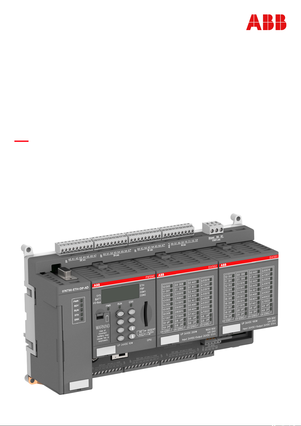
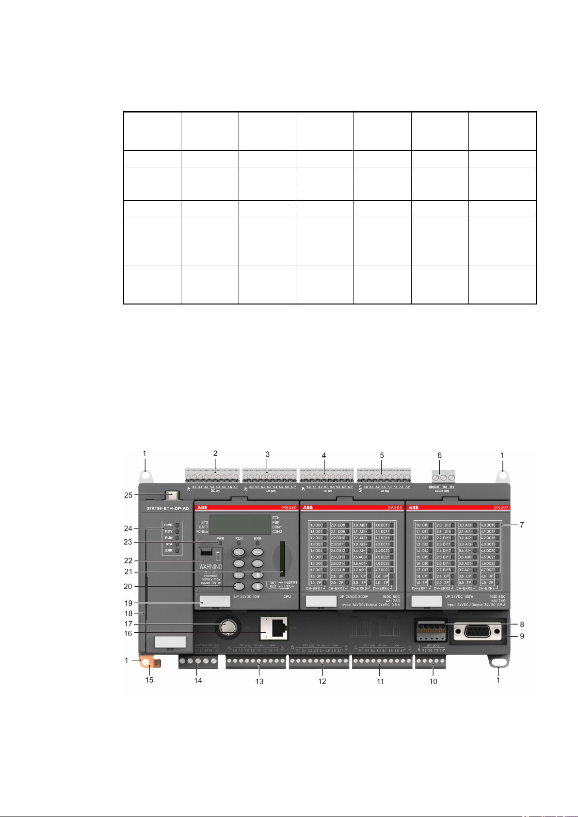
Fig. 17: 3ADR333186F0015_07KT98-ETH-DP-AD_Front
For information on the available I/O modules DA501 and DA502, please refer to the AC500 documentation. The CPU module used (here: PM590) depends on the model version.
2018/09/24 3ADR010122, 8, en_US 23

AC31 Adapters
Replacement devices: CPU > Replacement device 07KT9x-AD
No. Description
1 Hole for screw mounting (screw diameter 4 mm, extension torque 1.2 Nm)
2 Digital inputs/outputs for DA502
3 Digital inputs for DA501
4 Digital inputs for DA501
5 Analog inputs for DA501/DA502
6 CS31 bus Interface
7 Status LEDs for DA501/DA502
8 DIAG: Serial interface (diagnosis)
9 COM2: Serial interface (thread UNC 4-40)
10 Analog outputs for DA501/DA502
±10 V, 0 ... 20 mA, 4 ... 20 mA in one group
11 Digital inputs/outputs for DA501
12 Digital outputs for DA502
13 Digital outputs for DA502
14 Supply voltage connection 24 V DC (CPU and coupler)
15 Earth connection (FE). Connection for 6.3 mm Faston.
16 Ethernet: Network interface (function depends on device version)
17 Interface for ARCNET (BNC)
18 External networking interface
19 TA525: Label
20 8 operating buttons
21 SD memory card
22 Battery compartment for lithium battery TA521
23 3 system LEDs
24 5 status LEDs (only for PROFIBUS)
25 Connection for PROFIBUS (optional) (function depends on device version)
2018/09/243ADR010122, 8, en_US24
1.4.1.3.1 Electrical connection
AC31 Adapters
Replacement devices: CPU > Replacement device 07KT9x-AD
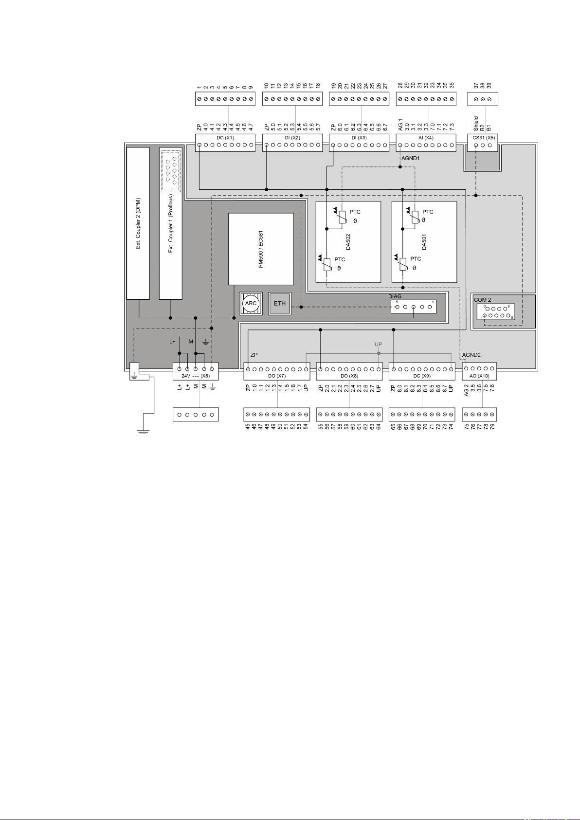
Fig. 18: Terminal assignment 07KT9x-AD
DIAG No electrical isolation (M)
COM2 Electrically isolated
CS31 bus Electrically isolated
Ethernet Electrically isolated
ARCNET Electrically isolated
DA501/DA502 Electrically isolated
Further information on earthing: Ä Chapter 1.3.1.7 “Earthing” on page 7.
Application example for connecting the inputs and outputs
Please observe the following information: Ä Chapter 1.3 “System data and CS31 bus system
data” on page 4
2018/09/24 3ADR010122, 8, en_US 25
AC31 Adapters
Replacement devices: CPU > Replacement device 07KT9x-AD
Connection of the supply voltage
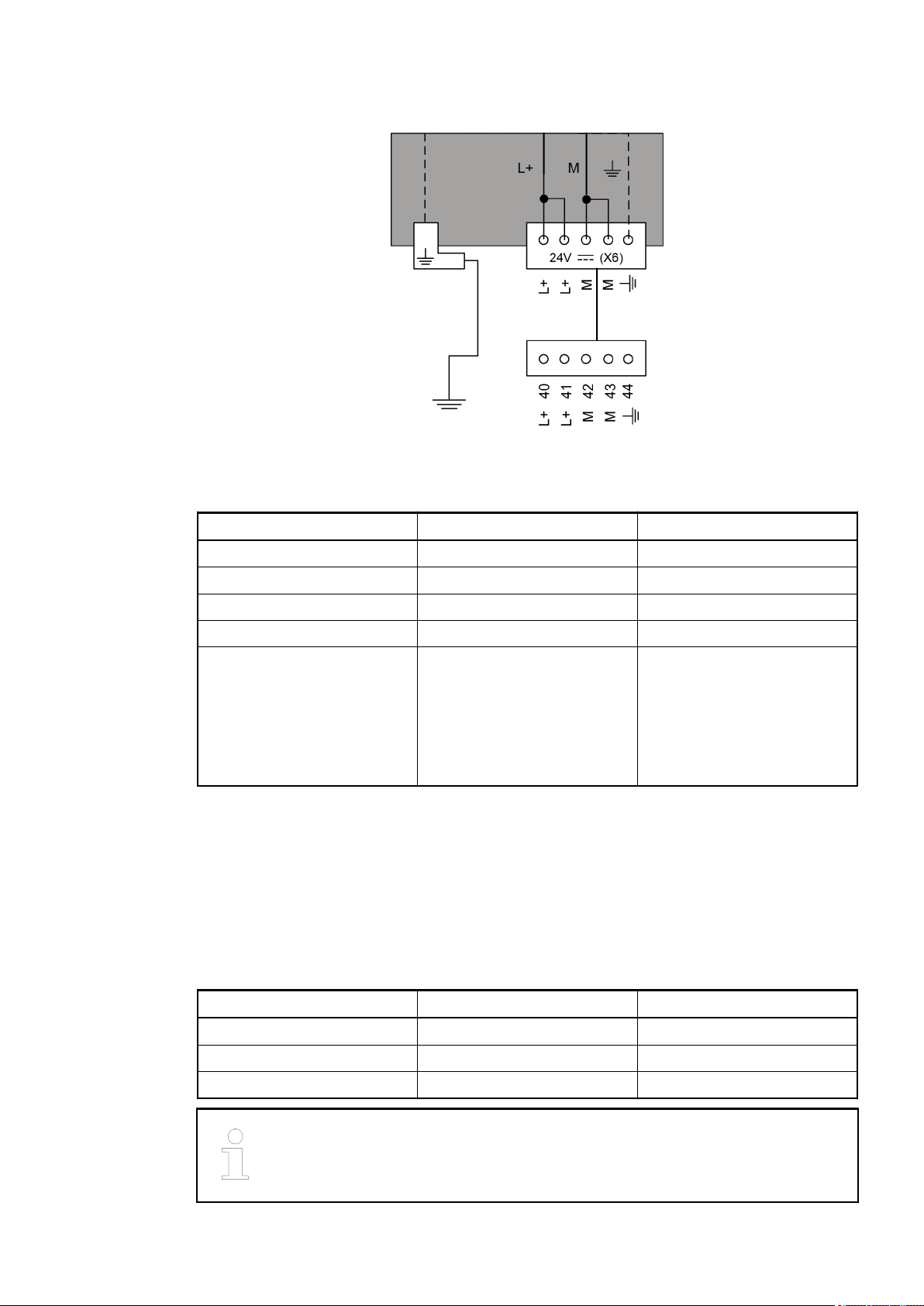
Fig. 19: Connection of the supply voltage
Table 12: Connector (X6)
Connector / Terminal Pin Assignment / Signal
X6 / L+ 40 Supply voltage +24 V DC
X6 / L+ 41 Supply voltage +24 V DC
X6 / M 42 Earth connection (0 V)
X6 / M 43 Earth connection (0 V)
X6 / functional earth 44 The functional earth (FE) is
connected to the Faston terminal inside the device.
Ensure that no earth loops are
created and that FE and
Faston are connected to the
same earthing potential.
● In addition to connecting the supply voltage (L+/M) to X6, the supply voltage (UP/ZP) must
be connected to all connectors.
● ZP must be connected to all connectors (X1, X2, X3, X7, X8, X9).
● UP must be connected to all connectors (X7, X8, X9).
● L+/M and UP/ZP must always be supplied with voltage.
Connection for CS31 bus
Table 13: Connector (X5)
Connector / Terminal Pin Assignment / Signal
X5 / shield 37 Shield (functional earth)
X5 / B2 38 BUS2
X5 / B1 39 BUS1
Terminal "Shield" is internally connected to FE. The previous earthing measures, e.g. with clip at the switchgear cabinet, are still required. Ä Chapter 1.3
“System data and CS31 bus system data” on page 4
2018/09/243ADR010122, 8, en_US26

If 07KT9x-AD is connected to one of the bus ends, a 120 Ω resistor must be connected for bus
AC31 Adapters
Replacement devices: CPU > Replacement device 07KT9x-AD
termination. The device 07KT9x-AD always functions as master. Slave operation is not possible.
Further information on CS31 bus: Ä Chapter 1.3 “System data and CS31 bus system data”
on page 4
Connection of digital inputs
See Ä Further information on page 25.
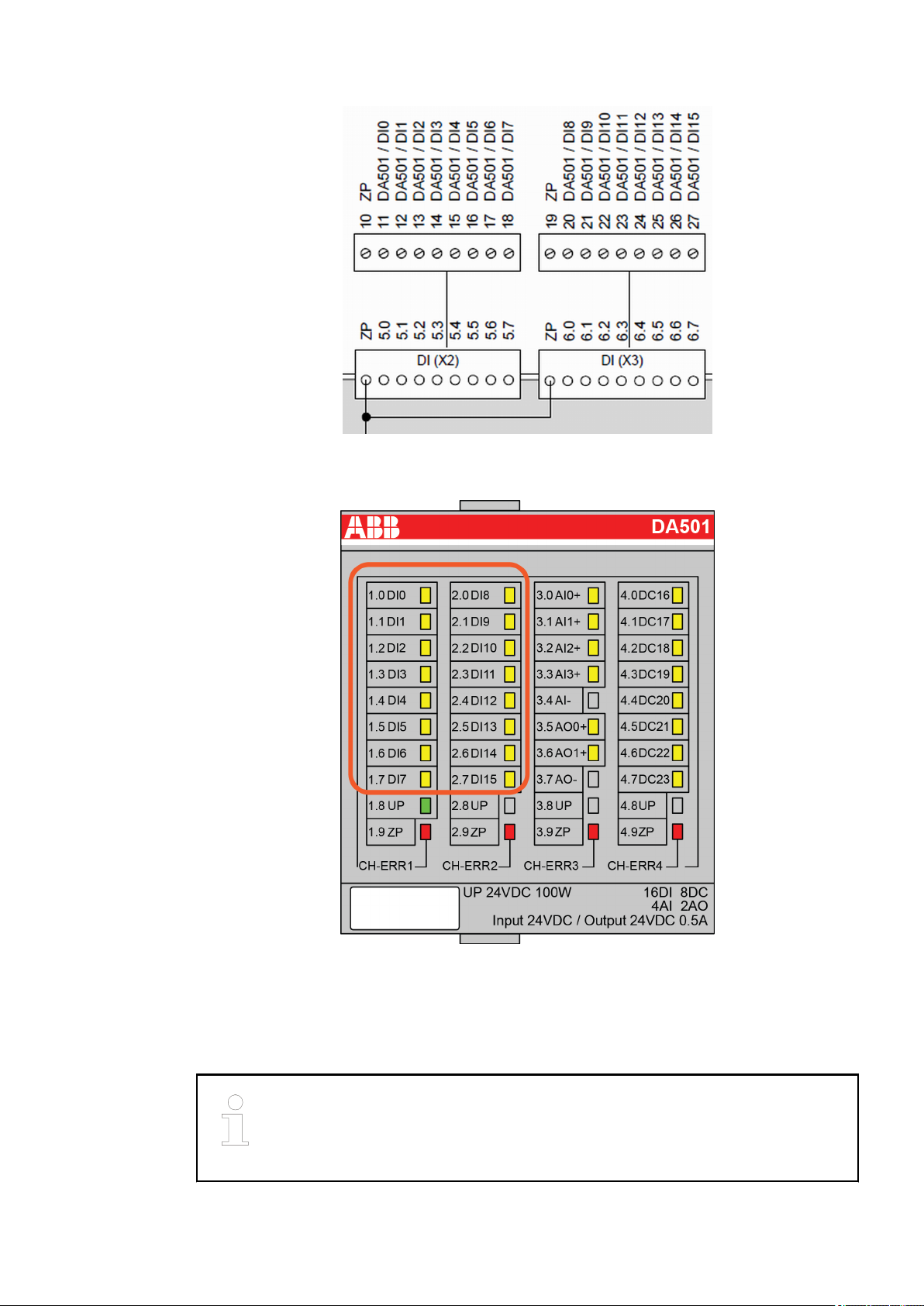
Table 14: Connector X2
Connector / Terminal Pin Assignment / Signal
X2 / ZP 10 ZP
X2 / 5.0 11 DA501 / DI0
X2 / 5.1 12 DA501 / DI1
X2 / 5.2 13 DA501 / DI2
X2 / 5.3 14 DA501 / DI3
X2 / 5.4 15 DA501 / DI4
X2 / 5.5 16 DA501 / DI5
X2 / 5.6 17 DA501 / DI6
X2 / 5.7 18 DA501 / DI7
Table 15: Connector (X3)
Connector / Terminal Pin Assignment / Signal
X3 / ZP 19 ZP
X3 / 6.0 20 DA501 / DI8
X3 / 6.1 21 DA501 / DI9
X3 / 6.2 22 DA501 / DI10
X3 / 6.3 23 DA501 / DI11
X3 / 6.4 24 DA501 / DI12
X3 / 6.5 25 DA501 / DI13
X3 / 6.6 26 DA501 / DI14
X3 / 6.7 27 DA501 / DI15
In contrast to the existing device 07KT98, the function of the digital inputs is only possible if
voltage UP is connected.
2018/09/24 3ADR010122, 8, en_US 27
AC31 Adapters
Replacement devices: CPU > Replacement device 07KT9x-AD
Fig. 20: Arrangement of the 16 digital inputs
The digital input states are always indicated by the LEDs DI0-DI15:
Fig. 21: DA501 LED status indication
Characteristics of the digital inputs:
● All 16 inputs have the same potential ZP as all other inputs/outputs. The electrical isolation
included in the existing devices is no longer available.
● Input delay (0->1 or 1->0): Typically 0.1 ms, configurable from 0.1 to 32 ms.
The signal coupling of the input signals is no longer realized via optocoupler. All
channels of the DA501 and DA502 modules have reference to ZP. The AGND1/
AGND2 of the analog channels are internally connected to ZP via PTC resistors. For information on terminal assignment, refer to figure Fig. 18).
2018/09/243ADR010122, 8, en_US28
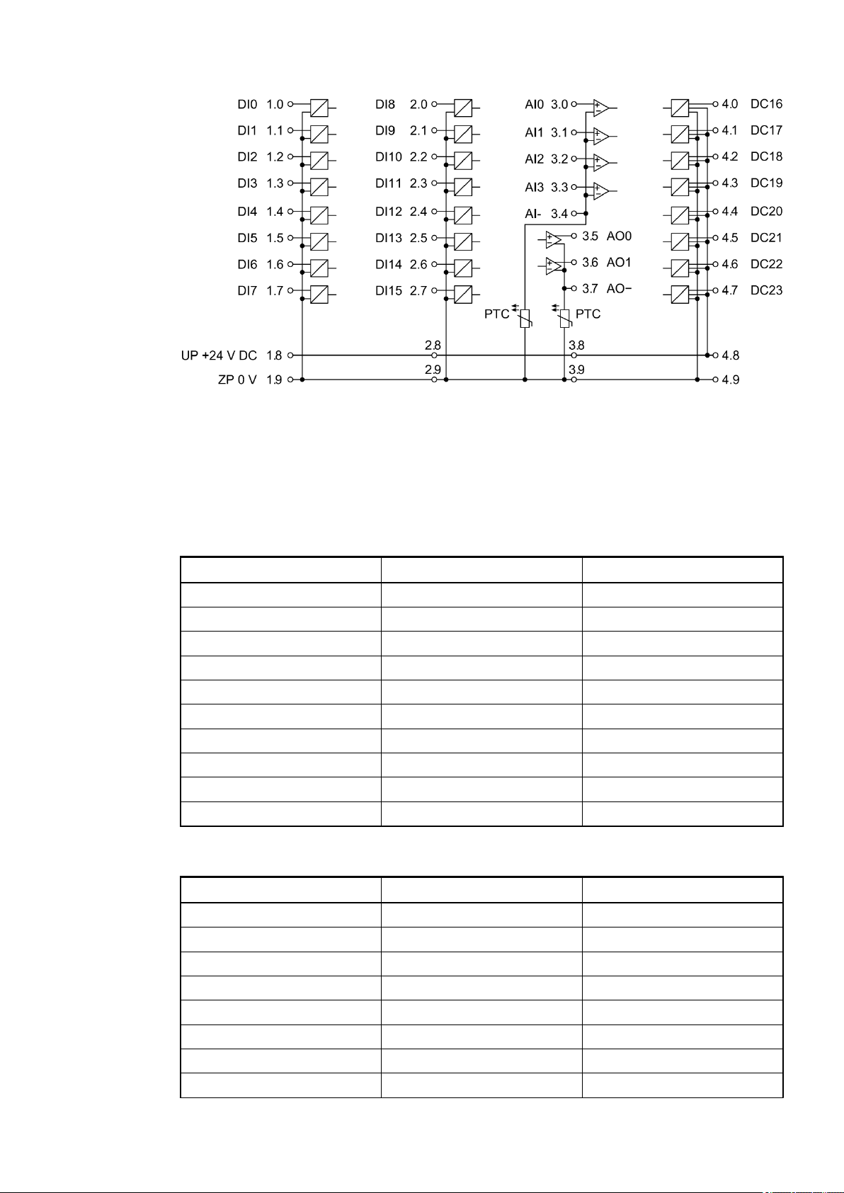
Fig. 22: Circuit arrangement of DA501 module
AC31 Adapters
Replacement devices: CPU > Replacement device 07KT9x-AD
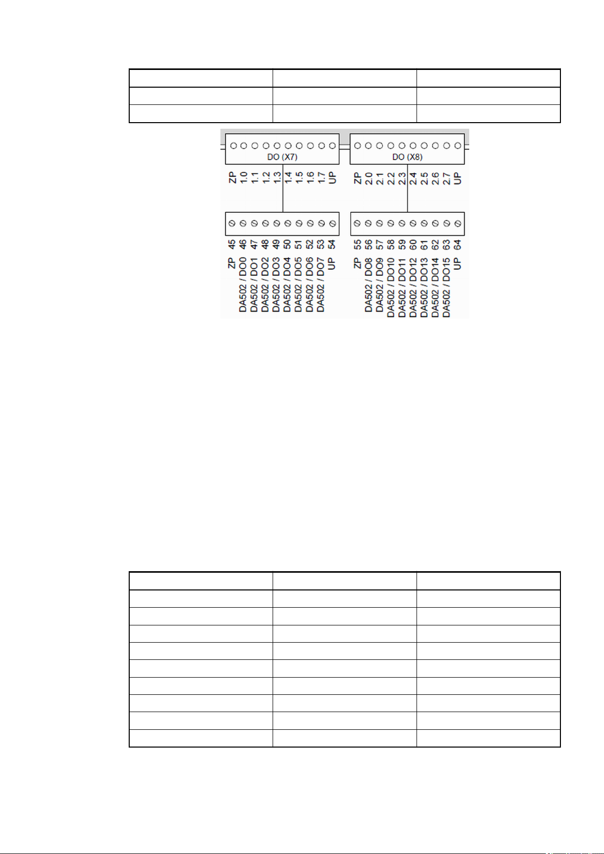
Connection of the digital outputs
See Ä Further information on page 25.
Table 16: Connector (X7)
Connector / Terminal Pin Assignment / Signal
X7 / ZP 45 ZP
X7 / 1.0 46 DA502 / DO0
X7 / 1.1 47 DA502 / DO1
X7 / 1.2 48 DA502 / DO2
X7 / 1.3 49 DA502 / DO3
X7 / 1.4 50 DA502 / DO4
X7 / 1.5 51 DA502 / DO5
X7 / 1.6 52 DA502 / DO6
X7 / 1.7 53 DA502 / DO7
X7 / UP 54 UP
Table 17: Connector (X8)
Connector / Terminal Pin Assignment / Signal
X8 / ZP 55 ZP
X8 / 2.0 56 DA502 / DO8
X8 / 2.1 57 DA502 / DO9
X8 / 2.2 58 DA502 / DO10
X8 / 2.3 59 DA502 / DO11
X8 / 2.4 60 DA502 / DO12
X8 / 2.5 61 DA502 / DO13
X8 / 2.6 62 DA502 / DO14
2018/09/24 3ADR010122, 8, en_US 29
AC31 Adapters
Replacement devices: CPU > Replacement device 07KT9x-AD
Connector / Terminal Pin Assignment / Signal
X8 / 2.7 63 DA502 / DO15
X8 / UP 64 UP
Fig. 23: Arrangement of digital outputs
Characteristics of the digital outputs
● The digital output states are always indicated by the LEDs DO0-DO15 on DA501 module.
● All 16 outputs have the same potential ZP as all other inputs/outputs. The electrical isolation
included in the existing devices is no longer available.
● Diagnosis: Stored errors are indicated via an LED and can be accessed by the CPU (see
AC500 documentation).
Circuit arrangement of digital outputs
● Fig. 22
●Ä Further information on page 32
Connection of the digital inputs/outputs
Table 18: Connector (X1)
Connector / Terminal Pin Assignment / Signal
X1 / ZP 1 ZP
X1 / 4.0 2 DA502 / DC16
X1 / 4.1 3 DA502 / DC17
X1 / 4.2 4 DA502 / DC18
X1 / 4.3 5 DA502 / DC19
X1 / 4.4 6 DA502 / DC20
X1 / 4.5 7 DA502 / DC21
X1 / 4.6 8 DA502 / DC22
X1 / 4.7 9 DA502 / DC23
2018/09/243ADR010122, 8, en_US30
 Loading...