


TECHNICAL GUIDE
Radio Control Terminal
RCT
Version 2.0

Copyright© Ericsson Enterprise AB 2001.
All Rights Reserved.
EN/LZT 103 30 R1A
2

Contents
CHAPTER 1 INTRODUCTION......................................................................................................................5
CHAPTER 2 GLOSSARY OF TERMS.........................................................................................................6
CHAPTER 3 REQUIREMENTS .....................................................................................................................7
CHAPTER 4 RUNNING THE INSTALLATION PROGRAM..............................................................8
WELCOME...........................................................................................................................................................8
USER INFORMATION..........................................................................................................................................8
INSTALLATION DIRECTORY .............................................................................................................................. 8
SELECT COMPONENTS.......................................................................................................................................8
SELECT PROGRAM FOLDER ...............................................................................................................................9
INSTALLATION...................................................................................................................................................9
SETUP COMPLETE..............................................................................................................................................9
CHAPTER 5 SETTING UP THE MD110 RADIO SERVICE PROVIDER ......................................10
MD110 RADIO SERVICE PROVIDER DATA..................................................................................................10
The Communication port........................................................................................................................10
Devices.......................................................................................................................................................11
Tape configuration...................................................................................................................................12
Detector settings .......................................................................................................................................14
Audio levels...............................................................................................................................................15
Side-tone and mute configuration.........................................................................................................16
Telephony configuration.........................................................................................................................17
REMOVING THE MD110 RADIO SERVICE PROVIDER.................................................................................19
LOADING TIU SOFTWARE..............................................................................................................................19
3

CHAPTER 6 SETTING UP THE RCT APPLICATION........................................................................20
USER PROFILE..................................................................................................................................................20
USER CONFIGURATION...................................................................................................................................24
ROLES................................................................................................................................................................29
CHANNELS........................................................................................................................................................31
ROLES AND CHANNELS DATABASE ............................................................................................................... 32
ODBC SETUP ..................................................................................................................................................33
Roles...........................................................................................................................................................33
Channels....................................................................................................................................................34
Roles and Channels database................................................................................................................34
SAFETY ............................................................................................................................................................. 35
CHAPTER 7 REFERENCES ..........................................................................................................................36
4

Chapter 1
Introduction
This document describes how to install and set-up the Radio Control Terminal (RCT) including
the Radio Service Provider for MD110 CA.
5

Chapter 2
Glossary of terms
CA Control Application
TAPI Telephony Application Programming Interface
ODBC Open DataBase Connectivity
CD Compact Disk
TIU Terminal Interface Unit
GPP TX General Purpose Port transmit
PABX Public Automatic Branch Exchange
6

Chapter 3
Requirements
These are the minimum hardware requirements:
• MD110 with BC 10
• TIU
• PC or compatible equipped with mouse and keyboard
• 266 MHz Pentium processor
• 64 MB RAM
• Min. 100 MB of free hard disk space
• 800x600 VGA screen
• Windows NT 4.0 or Win2000
• Network connection
• CD-drive
The hardware is installed according to instructions in ref. [1].
Software requirements for workstation:
• Windows NT 4.0 (Service Pack 4) or later or Win2000
• TAPI 2.x
• ODBC 3.0
7

Chapter 4
Running the installation program
To begin the installation, place the CD in the appropriate drive. If the PC is not set up with the
"Autorun" feature on the CD-drive, press the “Start” button and click on “Run”. Enter the
command
<CD-drive>:\Setup
and press “OK”.
Welcome
First the installation program displays some general information. Click Next to continue.
User information
Next the installation program prompts for your name and company. Click Next.
Installation directory
The installation program prompts you to select an installation directory. The default is
“C:\Program Files\Ericsson\Radio Control terminal". If you accept the default press Next,
otherwise select a new directory by using the Browse button.
Select components
Now you can choose which components to include in the installation. If the TIU is to be loaded
as well, select Tools also. If you want the User's Guide, the Quick Reference and this Technical
Guide on-line as well, select the Documentation files also. This dialog displays the amount of
disk space required as well as the available disk space.
8

When Next has been pressed, the installation program will check if there are any database files
on the hard drive. If there are, and the check box for database files is marked, a question will be
presented, asking if the database files on the hard drive shall be overwritten. If the answer is Yes
the files on the hard drive are renamed with the suffix _old.
Select program folder
Next the installation program prompts you to select a program folder in which to save the
program icons. The default is "Ericsson Radio Control Terminal". If you accept the default press
Next, otherwise enter a new name for the group.
Installation
The installation program now copies all necessary files to the specified directory. Finally, it
creates a new program group and places the program icons in it. At this point the installation is
complete. You should then read the “README.TXT” file, which contains additional
information about the products installed.
Setup complete
Now the installation of the RCT is complete. If "Tools" was installed, then it is possible to
choose if the TIU loader program shall be started. Click Finish to exit the installation program.
9

Chapter 5
Setting up the MD110 Radio Service
Provider
Select the “Telephony” (“Phone and Modem Options” for Win2000) applet in the "Control
Panel". Now the “Dialing Properties” dialogue appears. If the "Telephony drivers" (“Advanced”
for Win2000) tab is not shown, complete the "Dialing Properties" dialogue first and the tab will
appear. Select the “Telephony drivers” (“Advanced” for Win2000) tab and add the "RADIO
Service Provider" to the list of drivers by pressing "Add", selecting it and clicking on the “Add”
key once more.
When the new driver is installed press the “Configure” key in order to set it up. A configuration
dialogue appears. Set the “Connected port” setting to the serial port to which the TIU is
connected. When all settings are specified, press “OK”. Close the “Dialing Properties” dialogue.
The set-up is now completed.
MD110 Radio Service Provider Data
Modifications of the Radio Service Provider Data, also called position data, can be done after
the "MD110 Radio Service Provider" has been installed as described above.
The configuration dialog consists of seven different tab dialogs, which can be activated by
pressing the tabs.
All configuration data of the "MD110 Radio Service Provider” can be changed when the RCT
application is running, and changes in the configuration will be activated immediately after the
“OK” button has been pressed. The position configuration is stored in the Registry of each PC
under the HKEY_LOCAL_MACHINE key.
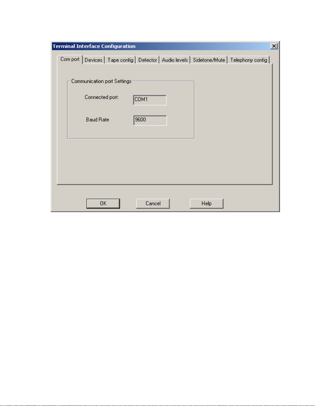
The Communication port
The “Com port” tab shows the Baud rate, and serial port settings. Note that the baud rate setting
cannot be altered.
10
Devices
In the “Devices” tab, there exist five “check boxes” representing external equipment. Check
each equipment so that this configuration matches the equipment connected to the TIU at this
position.
11

Tape configuration
The TIU has two different TAPE outputs, which can be used for voice recording. Opening the
TIU hardware can access the connectors for these outlets.
The connectors for “Tape 2” are marked “GPP TX” inside the TIU. Ref. [1].
Each tape device can be configured to the following:
1. None: No sound will be recorded.
2. Follow Radio: All radio sound will be recorded.
3. Follow Telephony: All telephony sound will be recorded.
12

4. Follow Both: All radio and telephony sound will be recorded.
Also in the “Tape configuration” tab the “Relay activation” can be configured. The “Relay
activation” is independent of the “Tape Configuration”, but is placed under the “Tape Config”
tab, since it is intended to be used for controlling activation of an external tape device. The relay
can be activated by the following external events or by any combination of them.
• PTT: When PTT is activated on the position.
• Squelch: When the TIU receives squelch indication ON from the PABX.
• Telephony: When a telephony call exists.
13

Detector settings
The TIU has speech detectors on the radio and telephony lines. The detectors control the
switching of received audio to the positions speaker and headset. The speech detectors for both
radio and telephony are configured together. The speech detector configuration consist of:
• Attack level: The level in dB that the audio must exceed before the detector triggers and
audio is connected. The Attack level can be adjusted between 0 and -52 dB.
• Attack time: The time in milliseconds the audio must exceed the Attack level before the
detector triggers and audio is connected. The Attack time can be adjusted between 0 and
200 milliseconds.
• Release level: The level in dB that the audio must drop below before a timer is activated.
This timer is called the Release timer. The Release level can be adjusted between 0 and
-55 dB.
• Release time: The time in milliseconds the audio must be below the Release level before
another timer is activated. This timer is called the Hold timer. The Release time can be
adjusted between 0 and 800 milliseconds.
• Hold time: The time in seconds the audio must be below the Attack level before the
audio is disconnected. The Hold time can be adjusted between 0 and 5 seconds.
14

Audio levels
Each audio input and output of the TIU, except the tape outputs, can be configured with an
attenuation or gain. Microphones have attenuations, while speakers have gains. The value of the
gain/attenuation must be adjusted in accordance with country regulations and quality of
telephony lines. The gain/attenuation can be adjusted between 0 and 25.5 dB (255) attenuation.
Lower values on microphone attenuations results in a higher audio level, while lower values on
speaker gains results in a lower audio level.
The "GPP gain" controls the received audio level from the General Purpose Port.
The gain/attenuation should not be adjusted during normal operation of the RCT.
15

Side-tone and mute configuration
The TIU provides side-tone audio to both the headset and handset speakers. The audio level of
the side-tone audio can be configured individually for telephony and radio audio. The level can
be adjusted between 6 dB and 21 dB attenuation in the configuration menu, according to either
user preferences or country regulations. Higher values produce lower side-tone level.
The TIU can also attenuate audio from other radio channels in the common speaker when PTT
is pressed on the RCT. This value can be configured to prevent unwanted audio from being
transmitted to the mobile units (e.g. police radios). The value is configured in the “Own PTT”
box. The value can be adjusted between 10 dB and 46 dB attenuation in the configuration menu,
according to user preferences. A high value results in a higher mute level and therefore in a
lower possibility for unwanted audio from being transmitted to the mobile units.
16

The "Own PTT" mute level also controls the attenuation of the telephony audio level in the
external speaker.
If several RCT positions are located in the same room, audio from one position's external
speaker might be re-transmitted via a microphone at another position and transmitted to the
mobile units when this position presses PTT. To prevent this from happening, the TIU can be
configured to attenuate the audio in the external speaker, when other positions press PTT. The
value is configured in the “Other PTT” box. The value can be adjusted between 10 dB and 46
dB attenuation in the configuration menu, according to user preferences. A higher value results
in a higher mute level and therefore in a lower possibility for unwanted audio from being
transmitted to the mobile units.
Telephony configuration
The routing of telephony audio to the handset, headset and external speaker is controlled by
both the RCT and PABX. The PABX offers two different modes Loud-speaking and Low-
speaking.
Normally Low-speaking means that the audio is directed to and from the handset, while Loudspeaking means that the audio is directed to a speaker.
17

The Audio configuration dialogue gives the possibility for the user to control which devices that
are active in the Loud-speaking and Low-speaking modes.
Loud-speaking can be configured to either common speaker or as specified by the Audio
window in the RCT application. The “Loud-speaking” combo box controls the configuration.
Low-speaking can be configured to either common speaker, handset, headset, both handset and
headset or as specified by the Audio window in the RCT application. The “Low-speaking”
combo box controls the configuration.
18

Removing the MD110 Radio Service Provider
Select the “Telephony” applet in the "Control Panel". Now the “Dialing Properties” dialogue
appears. Select the “Telephony drivers” tab and then select the MD110 Radio Service Provider
from the list of drivers. Press, “Remove” and confirm the removal.
Loading TIU software
The installation program of the RCT will install a program, which can be used for loading
software to the TIU. This program is named PC2TIU.exe, and can be found in the default
directory: C:\Program Files\Ericsson\Radio Control Terminal\tools\.
For further information see ref. [2].
19

Chapter 6
Setting up the RCT application
In order to use the RCT application, there are a number of settings that must be performed. The
registry on each workstation must be updated with a User Profile and User Configuration for
each user. The role files must be prepared and the channel file must be filled in with channel
data.
The installation program creates the keys in the registry and default values are established.
Modifications to the User Profile and user Configuration is done by working directly in the
registry. Press the “Start” button and click on “Run”. Type “Regedit” and press “OK”. The
Registry editor is now opened and the individual items can be modified.
User Profile
The privileges and limitations for each user must be specified in the User Profile in the registry
under HKEY_CURRENT_USER\Software\Ericsson\RCT\Profile.
The registry keys are defined as follows (default values in bold type):
20
Key name Values Description
Supervisor 0 - Operator
1 - Supervisor
RadioApplAllowed 0 - No
1 – Yes
For future use.
Defines whether the user may
start the RCT application.

ResizeRadioAppl 0 – No
1 - Yes
Defines whether the user may
resize the Channel List window.
ReposRadioAppl 0 – No
Defines whether the user may
move the Channel List window.
1 – Yes
MinimizeRadioAppl 0 – No
Defines whether the user may
minimize (iconize) the Channel
1 – Yes
List window.
ResizeAudioAppl Not used.
ReposAudioAppl 0 - No
Defines whether the user may
move the Audio window.
1 - Yes
MinimizeAudioAppl 0 - No
Defines whether the user may
minimize (iconize) the Audio
1 - Yes
window.
ResizeRadioFuncBar Not used
ReposRadioFuncBar 0 - No
Defines whether the user may
move the function bar.
1 - Yes
MinimizeRadio
FuncBar
0 - No
Defines whether the user may
minimize (iconize) function bar.
1 - Yes
XCPermit 0 - No
1 - Yes
DeassignAllowed 0 - No
1 - Yes
Defines whether the user may
set up cross-coupling groups.
Defines whether the user may
de-assign channels.
21

OnTopSwitchAllowed 0 - No
1 - Yes
Defines whether the user may
toggle the Always On Top.
MoreAssignsAllowed 0 - No
Defines whether the user may
assign additional channels.
1 - Yes
RSpeakerAllowed 0 - No
Defines whether the user may
route the radio audio to the
1 - Yes
speaker.
TSpeakerAllowed For future use.
RadioAppl
ExitAllowed
0 - No
Defines whether the user may
exit the RCT application.
1 - Yes
AudioAppl
ExitAllowed
0 - No
Defines whether the user may
exit the Audio window.
1 - Yes
TelephoneMute
Allowed
0 - No
Defines whether the user may
mute the telephony audio.
1 - Yes
BuzzerChange
Allowed
0 - No
Defines whether the user may
modify the buzzer type.
1 - Yes
GPPAllowed 0 - No
Defines whether the user may
activate the auxiliary audio
1 - Yes
input.
22
Paths For future use.
RMinHeadsetVol 0-200 Defines the minimum volume
level that the user can set for the
headset.

RMinHandsetVol 0-200 Defines the minimum volume
level that the user can set for the
handset.
RMinSpeakerVol 0-200 Defines the minimum volume
level that the user can set for the
speaker.
TMinHeadsetVol Not used.
TMinHandsetVol Not used.
TminSpeakerVol Not used.
MinBuzzerVol 0-200 Defines the minimum volume
level that the user can set for the
buzzer.
MinGPPVol 0-200 Defines the minimum volume
level that the user can set for the
auxiliary audio input.
ToggleOneOnly
Allowed
ToggleSaveOnExit
Allowed
MicWhenRadioIn
Speaker
0 - No
1 - Yes
0 - No
1 - Yes
1 - Handset
2 - External
4 - Headset
Defines whether the user may
toggle the button, which allows
more than one audio devices to
be connected simultaneously.
Defines whether the user may
toggle the Save On Exit
switches in the Channel List and
Audio windows.
Defines the microphone that
will be activated when the Radio
audio is routed to the external
speaker.
23

User Configuration
The settings for each user must be specified in the User Profile in the registry under
HKEY_CURRENT_USER\Software\Ericsson\RCT\Configs. These settings will be modified
automatically when running the application if the Save On Exit switches are set.
The registry keys are defined as follows:
Key name Values Description
RadioApplMinimized 0 - No
1 - Yes
FuncbarMinimized 0 - No
1 - Yes
AudioDevsOneOnly 0 - No
1 - Yes
RestoreOnSquelch 0 - No
1 - Yes
AlwaysOnTop 0 - No
1 - Yes
RadioApplPosX 0-max X
0x2ea
Defines whether the Channel
List window shall be started
minimized (iconized).
Defines whether the Radio
function bar shall be started
minimized (iconized).
Defines whether the only
one device shall be active at
startup of the Audio
window.
Defines whether the Channel
List window shall be
restored - if minimized - on
squelch.
Defines whether the Channel
List window always shall be
on top of other windows.
Defines the x-position of the
Channel List window at
startup.
24
RadioApplPosY 0-max Y
0xf2
Defines the y-position of the
Channel List window at
startup.

FuncbarPosX 0-max X
0x38d
Defines the x-position of the
Radio function bar at startup.
FuncbarPosY 0-max Y
0x7c
IndVolPosX 0-max X
0x3af
IndVolPosY 0-max Y
0x1e2
RadioApplSizeCX 0-max X
0x1dd
RadioApplSizeCY 0-max Y
0xb9
DefaultRole String
bob.rol
RHandsetState 0 - Off
1 - On
Defines the y-position of the
Radio function bar at startup.
Defines the x-position of the
Individual volume window.
Defines the y-position of the
Individual volume window.
Defines the width of the
Channel List window at
startup.
Defines the height of the
Channel List window at
startup.
Defines the name of the
default role file for the user.
Defines whether the handset
shall be activated for radio
audio at startup of the Audio
window.
RHeadsetState 0 - Off
1 - On
Defines whether the headset
shall be activated for radio
audio at startup of the Audio
window.
25

RSpeakerState 0 - Off
1 - On
Defines whether the speaker
shall be activated for radio
audio at startup of the Audio
window.
AudioApplMinimized 0 - No
1 - Yes
RadioSaveOnExit 0 - No
1 - Yes
AudioSaveOnExit 0 - No
1 - Yes
AudioApplPosX 0-max X
0x2ee
AudioApplPosY 0-max Y
0x155
HeadsetBalance 0-40
20
HandsetBalance 0-40
20
Defines whether the Audio
window shall be started
minimized (iconized).
Defines whether the "Save
on exit" switch shall be
checked for the Channel List
window.
Defines whether the "Save
on exit" switch shall be
checked for the Audio
window.
Defines the x-position of the
Audio window at startup.
Defines the y-position of the
Audio window at startup.
Defines the balance between
the Radio and Telephony
audio on the headset.
Defines the balance between
the Radio and Telephony
audio on the handset.
26
SpakerBalance 0-40
20
Defines the balance between
the Radio and Telephony
audio on the speaker.

RHeadsetVol 0-200
100
Defines the volume level for
the headset at startup of the
Audio window.
RHandsetVol 0-200
100
RSpeakerVol 0-200
100
BuzzerType 1-8
2
BuzzerVol 0-200
100
GPPVol 0-200
100
GPPOn 0 - Off
1 - On
Defines the volume level for
the handset at startup of the
Audio window.
Defines the volume level for
the speaker at startup of the
Audio window.
Defines the buzzer type at
startup of the Audio
window.
Defines the volume level for
the buzzer at startup of the
Audio window.
Defines the volume level for
the auxiliary audio input at
startup of the Audio
window.
Defines whether playback
from the auxiliary audio
input shall be active at
startup of the Audio
window..
ColumnSizeX Defines the width of the Xth
column in the Channel List
window. Only columns 1 to
6 are used. The rest are for
future use.
THeadsetVol Not used.
THandsetVol Not used.
27

TSpeakerVol Not used.
ColXEnabled 0 - Hidden
1 - Visible
FuncbarVisible 0 - Hidden
1 - Visible
RadioToolbarVisible 0 - Hidden
1 - Visible
RadioStatusbarVisible 0 - Hidden
1 - Visible
RadioMenuVisible 0 - Hidden
1 - Visible
RadioFilter 0 - All
1 - Rx+Rx/Tx
2 - Rx/Tx only
Defines if the Xth column in
the Channel List window
shall be visible or hidden.
Only columns 1 to 6 are
used. The rest are for future
use.
Defines if the Function bar
shall be visible or hidden.
Defines if the Toolbar in the
Channel List window shall
be visible or hidden.
Defines if the Status bar in
the Channel List window
shall be visible or hidden.
Defines if the Menu in the
Channel List window shall
be visible or hidden.
Defines the active filter (
minimum selection of the
radio channels to be
displayed ) in the Channel
List window.
28
DefaultDevice 1 - Handset
2 - Speaker
4 - Headset
Defines which device to
change back to if SPKROnly should toggle after
Speaker-key in Audio has
been pressed.

Roles
The data for each available role is stored in separate files. The access rights on the specific role
files together with the rights of the user define which roles that are available for a user.
Modifications of the role data are done directly in the role files. Use any editor, which can edit
(and store) plain text files.
A typical Role file looks like this:
"NetName","DefIndVolume","MinIndVolume","MaxIndVolume","DefModeSelection",
"MinModeSelection","MaxModeSelection","XCAllowed"
"CTY107", 4,3,6,2,2,2,0
"CTY110", 2,1,8,0,0,2,1
"CTY121", 6,6,8,1,1,2,0
The first line specifies the names of the data fields. These are:
1. NetName - defines the net name of the channel as specified in the PABX.
2. DefIndVolume - defines the individual volume level that will be used when assigning the
channel initially. Values: 1 - 8.
3. MinIndVolume - defines the minimum individual volume level that may be set for the
channel. Values: 1 - 8.
4. MaxIndVolume - defines the maximum individual volume level that may be set for the
channel. Values: 1 - 8.
5. DefModeSelection - defines the selection mode that will be used when assigning the
channel initially. Values: 0 = Idle, 1 = Rx, 2 = Rx/Tx.
6. MinModeSelection - defines the minimum selection mode that may be set for the
channel. Values: 0 = Idle, 1 = Rx, 2 = Rx/Tx.
7. MaxModeSelection - defines the maximum selection mode that may be set for the
channel. Values: 0 = Idle, 1 = Rx, 2 = Rx/Tx.
8. XCAllowed - defines if the channel may be part in a cross-coupling group . Values: 0 =
Not allowed, 1 = Allowed.
29

Example:
"CTY107", 4,3,6,2,2,2,0
The channel CTY107 above will be assigned with individual volume level 4, and will be
selected for Rx/Tx. The individual volume may be adjusted between 3 and 6, but the mode
selection cannot be changed. The channel may not be part of any cross-coupling group.
Two example Role files are provided with the RCT application. The files are stored in the
directory "Roles" under the RCT main directory and are called Dayshift.txt and Nightshift.txt.
30

Channels
The data for all channels is stored in one file. This file should be accessible for all users (Read
Only).
Modifications of the channel data are done directly in the channels file. Use any editor, which
can edit (and store) plain text files.
A typical channels file looks like this:
"NetName","Label","BmpFile"
"CTY107","West City", "P:\Bmps\Police.bmp"
"CTY108","North City", ""
The first line specifies the names of the data fields. These are:
1. NetName - defines the net name of the channel as specified in the PABX.
2. Label - defines the label that will be displayed on the operator position for the channel.
The label can contain up to 25 alphanumeric characters including spaces.
3. BmpFile - defines a bitmap that is displayed in front of the label on the operator position.
If this field is left empty (""), no bitmap will be displayed. The bitmap should be 16 by
16 pixels in size.
The channel CTY107 is shown as "West City" on the operator position and is also identified by
a bitmap. The channel CTY108 is identified as "North City" only.
An example Channels file is provided with the RCT application. The file is stored in the
directory "Channels" under the RCT main directory and is called Channels.txt.
31

Roles and Channels database
In the “Database files” directory there is also an example of an Access database that holds data
for both Roles and Channels. This database does not have to be an Access database, it can be
any relational database but the structure must look as the picture below:
The Channels table is to be filled exactly as the Channels file. The Roles table has a new field
compared to the file version. It is the TypeId field. This TypeId is an integer that corresponds to
the TypeId field in the RoleType table. The RoleType table is to be filled in with every Role
that exists in the system.
32

ODBC Setup
Note: The RCT requires ODBC 3.0 or later!
In order for the RCT to access the Roles and Channels files, the ODBC drivers have to be set
up. Click ODBC in the Control Panel. Select the ODBC Drivers tab and verify that the
'Microsoft Text Driver (*.txt, *.csv)' is present on the workstation. If not, it must be installed.
In order for the RCT to access the Roles and Channels relational database, the ODBC driver has
to be set up. Click ODBC in the Control Panel. Select the ODBC Drivers tab and verify that the
driver for the database you plan to use is present on the workstation. If not, it must be installed.
NOTE! If the Roles and Channels database is setup for RCT, the program will only use the
database, not the database files. To make the program use the files remove the DSN for Roles
and Channels database.
When the drivers have been installed as specified below, click OK and close the Control Panel.
Roles
Select the System DSN tab and click Add. Select the 'Microsoft Text Driver (*.txt, *.csv)' and
click Finish. In the Data Source Name field enter
RCT Roles
and in the Description field enter
RCT driver
Click Select Directory and specify the (local) directory on which the role files will be placed.
Click OK.
33

Channels
Select the System DSN tab and click Add. Select the 'Microsoft Text Driver (*.txt, *.csv)' and
click Finish. In the Data Source Name field enter
RCT Channels
and in the Description field enter
RCT driver
Click Select Directory and specify the (local) directory on which the channels file will be
placed. Click OK.
Roles and Channels database
Select the System DSN tab and click Add. Select the proper driver and click Finish. In the Data
Source Name field enter
RCT Db
and in the Description field enter
RCT driver
Click Select Directory and specify the (local) directory on which the channels file will be
placed. Click OK.
34

Safety
The user data for all users are stored in the Registry on the server. For safety reasons there
should exist a default user set-up on all PC’s. In this way a position can be used even if the
network is down.
Also a copy of the Channels and Role files should be available locally. The following procedure
is recommended:
1. The Channels and Roles files are located on a central server.
2. A script is implemented which copies the server files to the workstation at log-on.
3. In the ODBC set-up specify the local directories for accessing the Channels and Roles
files.
By following the above procedure the files can be administrated centrally while still retaining
local copies in case of a network failure.
35

Chapter 7
References
[1] Installation Instruction for Basic Module
[2] Technical Guide PC2TIU
36
 Loading...