

Page 1

53i, 55i, 57i, 57i C53i, 55i, 57i, 57i CT
SISIP I IP PHONE PHONE
41-001160-00
Rev 01
Administrator Guide
Release 2.0
Page 2

Aastra Telecom will not accept liability for any damages and/or long distance charges, which result from
unauthorized and/or unlawful use. While every effort has been made to ensure accuracy, Aastra Telecom will
not be liable for technical or editorial errors or omissions contained within this documentation. The
information contained in this documentation is subject to change without notice.
Copyright 2007 Aastra Telecom. www.aastra.com
All Rights Reserved.
Page 3

Software License Agreement
Aastra Telecom Inc., hereinafter known as "Seller", grants to Customer a
personal, worldwide, non-transferable, non-sublicenseable and non-exclusive,
restricted use license to use Software in object form solely with the Equipment for
which the Software was intended. This Product may integrate programs, licensed
to Aastra by third party Suppliers, for distribution under the terms of this
agreement. These programs are confidential and proprietary, and are protected as
such by copyright law as unpublished works and by international treaties to the
fullest extent under the applicable law of the jurisdiction of the Customer. In
addition, these confidential and proprietary programs are works conforming to the
requirements of Section 401 of title 17 of the United States Code. Customer shall
not disclose to any third party such confidential and proprietary programs and
information and shall not export licensed Software to any country except in
accordance with United States Export laws and restrictions.
Customer agrees to not reverse engineer, decompile, disassemble or display
Software furnished in object code form. Customer shall not modify, copy,
reproduce, distribute, transcribe, translate or reduce to electronic medium or
machine readable form or language, derive source code without the express
written consent of the Seller and its Suppliers, or disseminate or otherwise
disclose the Software to third parties. All Software furnished hereunder (whether
or not part of firmware), including all copies thereof, are and shall remain the
property of Seller and its Suppliers and are subject to the terms and conditions of
this agreement. All rights reserved.
Customer's use of this software shall be deemed to reflect Customer's agreement
to abide by the terms and conditions contained herein. Removal or modification
of trademarks, copyright notices, logos, etc., or the use of Software on any
Equipment other than that for which it is intended, or any other material breach of
this Agreement, shall automatically terminate this license. If this Agreement is
terminated for breach, Customer shall immediately discontinue use and destroy or
return to Seller all licensed software and other confidential or proprietary
information of Seller. In no event shall Seller or its suppliers or licensors be liable
for any damages whatsoever (including without limitation, damages for loss of
business profits, business interruption, loss of business information, other
pecuniary loss, or consequential damages) arising out of the use of or inability to
use the software, even if Seller has been advised of the possibility of such
damages.
41-001160-00, Rev 01 Release 2.0 iii
Page 4

Page 5

Contents
Preface
About this guide ...............................................................................................................xiii
Introduction ...............................................................................................................xiii.
Audience ...................................................................................................................xiii.
Other Documentation ............................................................................................... xiv.
Chapters and appendixes in this guide ..................................................................... xv.
Chapter 1
Overview
.
About this chapter ...........................................................................................................1-1.
IP Phone Models ............................................................................................................1-2.
Description ...............................................................................................................1-2.
Firmware Installation Information ...................................................................................1-4.
Description ...............................................................................................................1-4.
Installation Considerations .......................................................................................1-4.
Installation Requirements .........................................................................................1-5.
Configuration Server Requirement ...........................................................................1-6.
Firmware and Configuration Files ...................................................................................1-7.
Description ...............................................................................................................1-7.
Configuration File Precedence .................................................................................1-8.
Configuration Methods .............................................................................................1-8.
Installing the Firmware/Configuration Files ..............................................................1-9.
Contents
.
Chapter 2
Configuration Interface Methods
.
About this chapter ...........................................................................................................2-1.
IP Phone UI ....................................................................................................................2-2.
Options Key ..............................................................................................................2-4.
Aastra Web UI ................................................................................................................2-7.
Description ...............................................................................................................2-7.
41-001160-00, Rev 01 Release 2.0 v
Page 6

Contents
Chapter 3
Administrator Options
About this chapter ...........................................................................................................3-1.
Administrator Level Options ...........................................................................................3-3.
HTTP/HTTPS Support .............................................................................................2-7.
Using HTTPS via the Aastra Web UI .......................................................................2-9.
Accessing the Aastra Web UI ................................................................................2-10.
Status .....................................................................................................................2-12.
Operation ...............................................................................................................2-12.
Basic Settings ........................................................................................................2-13.
Advanced Settings .................................................................................................2-13.
Enabling/Disabling the Aastra Web UI ...................................................................2-14.
...............................................................................................................................2-14.
.
Description ...............................................................................................................3-3.
IP Phone UI Options ................................................................................................3-3.
Aastra Web UI Options ............................................................................................3-4.
Configuration File Options ........................................................................................3-4.
Phone Status ............................................................................................................3-6.
Basic Preferences (Aastra Web UI) .......................................................................3-10.
Network ..................................................................................................................3-12.
Line Settings ..........................................................................................................3-20.
Softkeys/Programmable Keys ................................................................................3-21.
Configuration Server Settings ................................................................................3-23.
Firmware Update Features ....................................................................................3-25.
...............................................................................................................................3-25.
Chapter 4
Network Configuration of the IP Phones
.
About this chapter ...........................................................................................................4-1.
Overview .........................................................................................................................4-3.
Basic Network Settings ...................................................................................................4-4.
DHCP .......................................................................................................................4-4.
Configuring Network Settings Manually ...................................................................4-7.
Configuring Ethernet Ports 0 and 1 Negotiation .......................................................4-9.
vi 41-001160-00, Rev 01 Release 2.0
Page 7

Configuration Server Protocol ......................................................................................4-13.
Configuring the Configuration Server Protocol .......................................................4-13.
Advanced Network Settings .........................................................................................4-18.
Network Address Translation (NAT) ......................................................................4-18.
Configuring Nortel NAT (optional) ..........................................................................4-20.
Configuring NAT Address and Port (optional) ........................................................4-22.
HTTPS Client/Server Configuration .......................................................................4-24.
Universal Plug and Play (UPnP) (for remote phones) ............................................4-28.
Virtual LAN (optional) .............................................................................................4-31.
Type of Service (ToS), Quality of Service (QoS), and DiffServ QoS ......................4-32.
Network Time Servers ............................................................................................4-41.
Session Initiation Protocol (SIP) Settings ...............................................................4-43.
Real-time Transport Protocol (RTP) Settings .........................................................4-56.
Chapter 5
Operational IP Phone Features
.
About this chapter ...........................................................................................................5-1.
Operational Features ......................................................................................................5-3.
Description ...............................................................................................................5-3.
User Passwords .......................................................................................................5-6.
Administrator Passwords .........................................................................................5-8.
Locking and Unlocking the Phone ............................................................................5-9.
Time and Date ........................................................................................................5-14.
Hard Keys ..............................................................................................................5-18.
Softkeys/Programmable Keys/Feature Keys .........................................................5-21.
Locking IP Phone Keys ..........................................................................................5-35.
Suppressing DTMF Playback .................................................................................5-37.
Display DTMF Digits ..............................................................................................5-39.
Busy Lamp Field (BLF) ..........................................................................................5-41.
BLF Subscription Period ........................................................................................5-48.
Directed Call Pickup (BLF or XML Call Interception) .............................................5-50.
Do Not Disturb (DND) ............................................................................................5-65.
Bridged Line Appearance (BLA) (57i/57i CT/53i only) ...........................................5-67.
Park Calls/Pick Up Parked Calls ............................................................................5-73.
Last Call Return (lcr) (Sylantro Servers only) .........................................................5-86.
Contents
41-001160-00, Rev 01 Release 2.0 vii
Page 8

Contents
Chapter 6
Advanced IP Phone Operational Features
About this chapter ...........................................................................................................6-1.
Advanced Operational Features .....................................................................................6-2.
Call Forwarding ......................................................................................................5-90.
Callers List .............................................................................................................5-96.
Missed Calls Indicator ..........................................................................................5-101.
Directory List ........................................................................................................5-103.
Voicemail (55i, 57i, and 57i CT only) ....................................................................5-113.
XML Customized Services ...................................................................................5-116.
SIP Local Dial Plan ..............................................................................................5-137.
Incoming/Outgoing Intercom with Auto-Answer ...................................................5-142.
Audio Transmit and Receive Gain Adjustments ...................................................5-146.
Ring Tones and Tone Sets ...................................................................................5-148.
Priority Alerting .....................................................................................................5-153.
Stuttered Dial Tone ...............................................................................................5-160.
Call Waiting Tone .................................................................................................5-162.
Language .............................................................................................................5-164.
.
MAC Address/Line Number in REGISTER Messages .............................................6-3.
SIP Message Sequence for Blind Transfer ..............................................................6-5.
Update Caller ID During a Call .................................................................................6-6.
Boot Sequence Recovery Mode ..............................................................................6-7.
Auto-discovery Using mDNS ....................................................................................6-8.
Single Call Restriction (57i CT only) ........................................................................6-9.
Chapter 7
Encryption and the IP Phone
.
About this chapter ...........................................................................................................7-1.
Encryption and the IP Phone ..........................................................................................7-2.
Configuration File Encryption Method ......................................................................7-2.
Procedure to Encrypt/Decrypt Configuration Files ...................................................7-3.
viii 41-001160-00, Rev 01 Release 2.0
Page 9

Chapter 8
Firmware Upgrade
.
About this chapter ...........................................................................................................8-1.
Upgrading the Firmware .................................................................................................8-2.
Manual Firmware Update (TFTP only) .....................................................................8-2.
Manual Firmware and Configuration File Update .....................................................8-4.
Automatic Update (auto-resync) ..............................................................................8-6.
......................................................................................................................................8-10.
Chapter 9
Troubleshooting
.
About this chapter ...........................................................................................................9-1.
Troubleshooting ..............................................................................................................9-2.
Troubleshooting Solutions ..............................................................................................9-8.
Description ...............................................................................................................9-8.
Why does my phone display “Application missing”? ................................................9-8.
Why does my phone display the “No Service” message? ........................................9-9.
Why does my phone display "Bad Encrypted Config"? ............................................9-9.
Why is my phone not receiving the TFTP IP address from the DHCP Server? .....9-10.
How do I set the IP phone to factory default? ........................................................9-13.
How to reset a user’s password? ...........................................................................9-16.
Contents
Appendix A
Configuration Parameters
.
About this appendix ....................................................................................................... A-1.
Setting Parameters in Configuration Files ..................................................................... A-4.
Operational, Basic, and Advanced Parameters ............................................................. A-5.
Network Settings ..................................................................................................... A-5.
Password Settings .................................................................................................. A-8.
Emergency Dial Plan Settings ................................................................................. A-9.
Aastra Web UI Settings ......................................................................................... A-10.
Configuration Server Settings ............................................................................... A-11.
Network Address Translation (NAT) Settings ........................................................ A-18.
HTTPS Client and Server Settings ........................................................................ A-20.
UPnP Settings ....................................................................................................... A-22.
Virtual Local Area Network (VLAN) Settings ......................................................... A-24.
41-001160-00, Rev 01 Release 2.0 ix
Page 10

Contents
Hard Key Parameters ................................................................................................ A-106.
Type of Service (ToS)/DSCP Settings ................................................................... A-27.
Time Server Settings ............................................................................................. A-28.
Time and Date Settings ......................................................................................... A-30.
SIP Local Dial Plan Settings ................................................................................. A-37.
SIP Basic, Global Settings .................................................................................... A-40.
SIP Basic, Per-Line Settings ................................................................................. A-48.
Advanced SIP Settings ......................................................................................... A-58.
RTP, Codec, DTMF Global Settings ...................................................................... A-63.
DTMF Per-Line Settings ........................................................................................ A-65.
Silence Suppression Settings ............................................................................... A-66.
Voicemail Settings ................................................................................................. A-67.
Directory Settings .................................................................................................. A-68.
Callers List Settings .............................................................................................. A-69.
Call Forward Settings ............................................................................................ A-69.
Missed Calls Indicator Settings ............................................................................. A-70.
XML Settings ......................................................................................................... A-71.
Action URI Settings ............................................................................................... A-74.
Ring Tone and Tone Set Global Settings .............................................................. A-77.
Ring Tone Per-Line Settings ................................................................................. A-78.
Stuttered Dial Tone Setting ................................................................................... A-79.
Call Waiting Tone Setting ...................................................................................... A-79.
Priority Alert Settings ............................................................................................. A-80.
Language Settings ................................................................................................ A-86.
Language Pack Settings ....................................................................................... A-87.
Suppress DTMF Playback Setting ........................................................................ A-96.
Display DTMF Digits Setting ................................................................................. A-97.
Intercom and Auto-Answer Settings ...................................................................... A-98.
Audio Transmit and Receive Gain Adjustment Settings ..................................... A-101.
Directed Call Pickup (BLF or XML Call Interception) Settings ............................ A-104.
BLF Subscription Period Settings ....................................................................... A-105.
Softkey Settings for 55i, 57i, 57i CT .................................................................... A-110.
Programmable Key Settings for 53i and 55i ........................................................ A-117.
Top Softkey Settings for 57i and 57i CT .............................................................. A-121.
x 41-001160-00, Rev 01 Release 2.0
Page 11

Handset Feature Key Settings for the 57i CT ..................................................... A-126.
Expansion Module Key Settings for 536M (53i/55i)
and 560M (57i/57i CT) ........................................................................................ A-128
Locking Softkeys and Programmable Keys ........................................................ A-131.
Advanced Operational Parameters ........................................................................... A-134.
MAC Address/Line Number ............................................................................... A-134.
Blind Transfer Setting. ......................................................................................... A-135.
Update Caller ID Setting. .................................................................................... A-136.
Boot Sequence Recovery Mode. ........................................................................ A-136.
Single Call Restriction ......................................................................................... A-137.
Troubleshooting Parameters ..................................................................................... A-138.
Log Settings ........................................................................................................ A-138.
Appendix B
Configuration Server Setup
.
About this appendix ....................................................................................................... B-1.
Configuration Server Protocol Setup ............................................................................. B-2.
TFTP Server Set-up ................................................................................................ B-2.
Appendix C
Configuring the IP Phone at the Asterisk IP PBX
.
About this appendix ....................................................................................................... C-1.
IP Phone at the Asterisk IP PBX ...................................................................................C-2.
Contents
.
Appendix D
Sample Configuration Files
.
About this appendix ....................................................................................................... D-1.
Sample Configuration Files ...........................................................................................D-2.
57i Sample Configuration File .................................................................................D-2.
57i CT Sample Configuration File ......................................................................... D-12.
53i Sample Configuration File ............................................................................... D-29.
41-001160-00, Rev 01 Release 2.0 xi
Page 12

Appendix E
Sample BLF Softkey Settings
About this appendix ....................................................................................................... E-1.
Sample BLF Softkey Settings ........................................................................................ E-2.
Contents
Appendix F
Sample Multiple Proxy Server Configuration
About this appendix ....................................................................................................... F-1.
Multiple Proxy Server Configuration .............................................................................. F-2.
Appendix G
Creating an XML Application
About this appendix .......................................................................................................G-1.
How to Create an XML Application ................................................................................G-3.
Limited Warranty
.
.
Asterisk BLF ............................................................................................................ E-2.
BroadSoft BroadWorks BLF .................................................................................... E-3.
.
.
Overview .................................................................................................................G-3.
XML format ..............................................................................................................G-3.
Creating XML Objects .............................................................................................G-4.
Creating Custom Softkeys ......................................................................................G-5.
Text Menu Object (Menu Screens) ..........................................................................G-6.
Text Screen Object (Text Screens) ..........................................................................G-8.
UserInput Object (User Input Screens) .................................................................G-13.
Directory Object (Directory List Screen) (57i only) ................................................G-21.
Status Message Object (Idle Screen) ....................................................................G-23.
Execute Commands Object (for executing XML commands) ...............................G-25.
Dynamic Configuration Object (to push a configuration to the phone) ..................G-27.
XML Image Objects (55i, 57i/57i CT only) ............................................................G-31.
Attributes/Options to Use with XML Objects .........................................................G-41.
HTTP Post .............................................................................................................G-45.
XML Schema File ..................................................................................................G-48.
xii 41-001160-00, Rev 01 Release 2.0
Page 13

About this guide
Introduction
This SIP IP Phone Administrator Guide provides information on the basic
network setup, operation, and maintenance of the IP phones, Models 53i, 55i, 57i,
and 57i Cordless (57i CT). It also includes details on the functioning and
configuration of the IP phones.
Note: Features, characteristics, requirements, and configuration that are
specific to a particular IP phone model are indicated where required in
this guide.
Audience
Preface
Preface
This guide is for network administrators, system administrators, developers and
partners who need to understand how to operate and maintain the IP phone on a
SIP network. It also provides some user-specific information.
This guide contains information that is at a technical level, more suitable for
system or network administrators. Prior knowledge of IP Telephony concepts is
recommended.
41-001160-00, Rev 01 Release 2.0 xiii
Page 14

IP Phone Administrator Guide
About this guide
Other Documentation
The IP phone documentation consists of:
• <Model-specific> SIP IP Phone Installation Guide – contains installation
and set-up instructions, information on general features and functions, and
basic options list customization. Included with the phone.
• Model 53i, 55i, 57i, 57i CT SIP IP Phone Administrator Guide – explains
Preface
how to set the phone up on the network, as well as advanced configuration
instructions for the SIP IP phone. This guide contains information that is at a
technical level more suitable for a system or network administrator.
• <Model-specific> SIP IP Phone User Guides – explains the most commonly
used features and functions for an end user.
This Administrator Guide complements the Aastra product-specific Installation
Guide and the Aastra product-specific User Guide.
xiv 41-001160-00, Rev 01 Release 2.0
Page 15

Chapters and appendixes in this guide
This guide contains the following chapters and appendixes:
For Go to
An overview of the IP Phone firmware installation information Chapter 1
IP Phone interface methods Chapter 2
Administrator option information Chapter 3
Configuring the IP Phone Chapter 4
Operational information about the IP Phones Chapter 5
Advanced operational information about the IP Phones Chapter 6
Encryption information Chapter 7
Firmware upgrade information Chapter 8
Troubleshooting solutions Chapter 9
Configuration parameters Appendix A
Configuration server setup Appendix B
Configuring the IP Phones at the Asterisk PBX Appendix C
Sample configuration files Appendix D
Sample BLF softkey settings Appendix E
Sample multiple proxy server configuration Appendix F
Creating XML applications Appendix G
Preface
41-001160-00, Rev 01 Release 2.0 xv
Page 16

Page 17

About this chapter
Introduction
This chapter briefly describes the IP Phone Models, and provides information
about installing the IP phone firmware. It also describes the firmware and
configuration files that the IP phone models use for operation..
Topics
This chapter covers the following topics:
Chapter 1
Overview
Overview
Topi c Page
IP Phone Models page 1-2
Firmware Installation Information page 1-4
Firmware and Configuration Files page 1-7
41-001160-00, Rev 01 Release 2.0 1-1
Page 18
IP Phone Administrator Guide
IP Phone Models
IP Phone Models
Description
The IP Phone Models 53i, 55i, 57i, and 57i CT communicate over an IP network
allowing you to receive and place calls in the same manner as a regular business
telephone.
Overview
All phone models support the Session Initiation Protocol (SIP). The 57i CT offers
the base phone along with a cordless extension.
References
For more information about the features and installation requirements, see the
SIP IP Phone Installation Guide for your specific model..
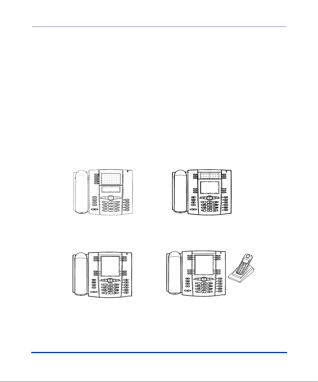
The following illustration shows the types of IP Phone Models.
3-Line LCD Display,
6 Programmable Keys
53i
55i
3-Line LCD Display,
6 Programmable Keys,
6 Softkeys
57i
11-Line LCD Display,
12 Softkeys
15 Feature Keys on Handset
1-2 41-001160-00, Rev 01 Release 2.0
57i CT
(includes handset)
12 Softkeys.
Page 19
Overview
IP Phone Models
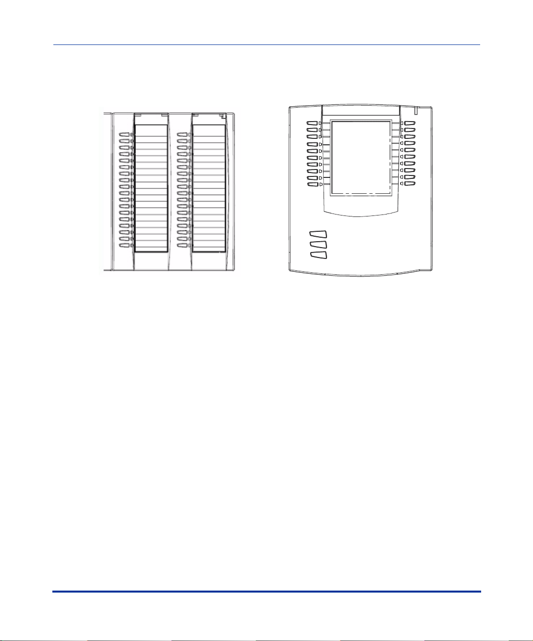
The following illustration shows IP phone optional accessories for the 55i, 57i,
and 57i CT IP phones.
Overview
536EM Expansion Module
for 55i, 57i, and 57i CT
The 536EM module adds 36 additional softkeys to the IP phone models 55i, 57i,
and 57i CT. The 536EM provides paper labels for each softkey. Up to 3 modules
can be piggy-backed to provide up to 108 additional softkeys for the phone.
The 560EM module adds 60 additional softekeys to the IP phone models 57i and
57i CT (using the 3 function keys on the bottom right of the unit). The 560EM
module provides an LCD display for display softkey labels. Up to 3 modules can
be piggy-backed to provide up to 180 additional softkeys for the phone.
Reference
For more information about installing and using the expansion modules, see your
phone-specific Installation Guide and User Guide.
560EM Expansion Module
for 57i, and 57i CT
41-001160-00, Rev 01 Release 2.0 1-3
Page 20

IP Phone Administrator Guide
Firmware Installation Information
Firmware Installation Information
Description
The firmware setup and installation for the IP phone can be done using any of the
following:
Overview
• Phone keypad menu (Phone UI)
• Aastra Web-based user interface (Aastra Web UI)
When the IP phone is initialized for the first time, DHCP is enabled by default.
Depending on the type of configuration server setup you may have, the IP phone
may download a firmware version automatically, or you may need to download it
manually.
Installation Considerations
The following considerations must be made before connecting the IP phone to the
network:
• If you are planning on using dynamic IP addresses, make sure a DHCP server
is enabled and running on your network.
• If you are not planning on using dynamic IP addresses, see Chapter 4, the
section, “Configuring Network Settings Manually” on page 4-7 for manually
setting up an IP address.
To install the IP phone hardware and cabling, refer to the model-specific
SIP IP Phone Installation Guide.
1-4 41-001160-00, Rev 01 Release 2.0
Page 21

Overview
Firmware Installation Information
Installation Requirements
The following are general requirements for setting up and using your SIP IP
phone:
• A SIP-based IP PBX system or network installed and running with a number
created for the new IP phone.
• Adherence to SIP standard RFC 3261.
• Access to a configuration server where you can store the firmware image and
configuration files.
• The IP phone must be configured for a specific type of protocol to use. TFTP
is enabled by default. You can configure the following protocols on the IP
phone:
— TFTP (Trivial File Transfer Protocol)
— FTP (File Transfer Protocol)
— HTTP (Hypertext Transfer Protocol)
— HTTPS (Hypertext Transfer Protocol over Secure Socket Layer)
Note: If you set TFTP, the configuration server must be able to accept
connections anonymously.
Overview
• A 802.3af Ethernet/Fast Ethernet LAN
• Category 5/5e straight through cabling
• Power over Ethernet (PoE) inline power injector (optional accessory –
necessary only if your network provides no inline power and if you do not use
the IP Phone’s power adapter).
• Power adapter (included for models 53i, 55i, and 57i, and 57i CT).
• Service provider must support 55i SIP IP phone.
41-001160-00, Rev 01 Release 2.0 1-5
Page 22

IP Phone Administrator Guide
Firmware Installation Information
Configuration Server Requirement
A basic requirement for setting up the IP phone is to have a configuration server.
The configuration server allows you to:
• Store the firmware images that you need to download to your IP phone.
• Stores configuration files for the IP phone
• Stores the software when performing software upgrades to the IP phone
Overview
Reference
To set the protocol for your configuration server, see Chapter 4, the section,
“Configuring the Configuration Server Protocol” on page 4-13.
For setting up your configuration server, see Appendix B, “Configuration Server
Setup.”
1-6 41-001160-00, Rev 01 Release 2.0
Page 23
Overview
Firmware and Configuration Files
Firmware and Configuration Files
Description
When the IP phone is initialized for the first time, DHCP is enabled by default.
Depending on the type of configuration server setup you may have, the IP phone
may download a firmware version and configuration files automatically, or you
may need to download it manually.
Note: Automatic download is dependant on your configuration server
setup.
The firmware consists of a single file called:
• <phone model>.st
The configuration files consist of two files called:
• aastra.cfg
•<mac>.cfg
The following table provides the firmware for each Aastra IP phone model.
Overview
IP Phone
Model
53i 53i.st2
55i 55i.st2
57i 57i.st2
57i CT 57i Cordless.st2
41-001160-00, Rev 01 Release 2.0 1-7
Associated
Firmware
Page 24

IP Phone Administrator Guide
Firmware and Configuration Files
Configuration File Precedence
Aastra IP phones can accept two sources of configuration data:
• The server configuration most recently downloaded/cached from the
configuration server files, aastra.cfg/<mac>.cfg (or the aastra.tuz/<mac>.tuz
encrypted equivalents).
• Local configuration changes stored on the phone that were entered using
either the IP phone UI or the Aastra Web UI
Overview
In the event of conflicting values set by the different methods, values are applied
in the following sequence:
1. Default values hard-coded in the phone software
2. Values downloaded from the configuration server
3. Values stored locally on the phone
The last values to be applied to the phone configuration are the values that take
effect.
For example, if a parameter’s value is set in the local configuration (via Aastra
Web UI or IP phone UI) and the same value was also set differently in one of the
<mac>.cfg/aastra.cfg files on the configuration server, the local configuration
value is the value that takes effect because that is the last value applied to the
configuration.
Configuration Methods
You can use the following to setup and configure the IP phone:
• IP phone UI
•Aastra Web UI
• Configuration files
Model 53i has 6 softkeys available for programming. Models 55i, 57i, and 57i CT
have 12 softkeys available for programming (programmable up to 20 functions).
1-8 41-001160-00, Rev 01 Release 2.0
Page 25

Overview
Firmware and Configuration Files
References
For setting up and configuring the IP phone using either the IP phone UI, the
Aastra Web UI, or the configuration files, see Chapter 4, “Network Configuration
of the IP Phones.”
For information about the softkey and programmable key parameters, see
Appendix A, the section, “Softkey/Programmable Key/Feature Key Parameters”
on page A-108.
Installing the Firmware/Configuration Files
The following procedure describes how to install the firmware and configuration
files.
Step Action
1 If DHCP is disabled, manually enter the configuration server’s IP address. For details on setting
DHCP, see Chapter 4, the section “DHCP” on page 4-4.
2 Copy the firmware file <phone model>.st to the root directory of the configuration server. The IP
phone accepts the new firmware file only if it is different from the firmware currently loaded on the IP
phone.
Overview
Note: The <phone model> attribute is the IP phone model (i.e., 53i.st, 55i.st)
3 Copy the Aastra configuration files (aastra.cfg and <mac>.cfg) to the root directory of the
configuration server.
Note: The <mac> attribute represents the actual MAC address of your phone.
(i.e., 00085D030996.cfg).
4 Note: Restart tthe IP phone as described in the section, “How to Restart the IP Phone” on page .
41-001160-00, Rev 01 Release 2.0 1-9
Page 26

Page 27
Configuration Interface Methods
About this chapter
Introduction
This chapter describes the methods you can use to configure the IP phones..
Note: Features, characteristics, requirements, and configuration that are
specific to a particular IP phone model are indicated where required in
this guide.
Topics
Chapter 2
Configuration Interface Methods
This chapter covers the following topics:
Topi c Page
IP Phone UI page 2-2
Aastra Web UI page 2-7
41-001160-00, Rev 01 Release 2.0 2-1
Page 28
IP Phone Administrator Guide
IP Phone UI
IP Phone UI
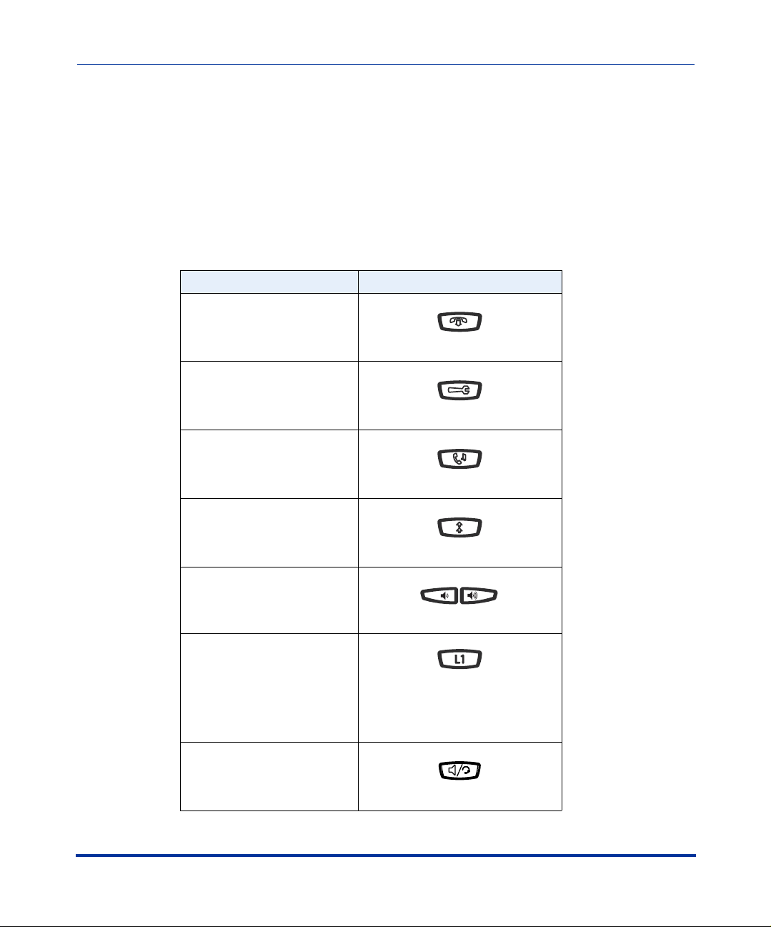
The IP Phone User Interface (UI) provides an easy way to access features and
functions for using and configuring the IP phone. You can use the following
hardkeys to perform specific functions and display information to the phone’s
LCD display on all phone models:
IP Phone Hard Key Looks Like This:
Goodbye Key
Options Key
Hold Key
Redial Key
Volume Control Keys
Configuration Interface Methods
2-2 41-001160-00, Rev 01 Release 2.0
Line/Call Appearance Keys
(See your model-specific User
Guide for applicable Line/Call
Appearance keys for your phone
model.)
Speakerphone/Headset Key
Page 29
Configuration Interface Methods
IP Phone UI
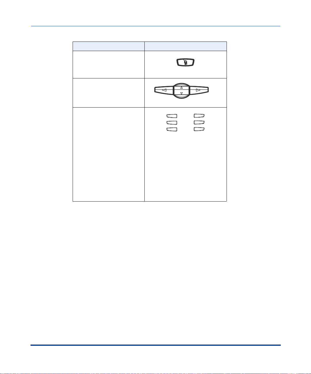
IP Phone Hard Key Looks Like This:
Mute Key
Navigation Keys
Softkeys/Programmable
Keys
Softkeys and programmable keys
vary for each phone model. See
your model-specific User Guide
for applicable keys. For setting
functions on the softkeys/
programmable keys, see Chapter
5, the section, “Softkeys/
Programmable Keys/Feature
Keys” on page 5-21
Configuration Interface Methods
By default, specific softkeys/programmable keys on each phone model can also
access the Directory List and Callers List, and initiate transfers and conference
calls.
Reference
For more information about using the hard keys, see Chapter 5, the section, “Hard
Keys” on page 5-18. For more information about the softkeys/programmable
keys, see Chapter 5, the section, “Softkeys/Programmable Keys/Feature Keys” on
page 5-21.
41-001160-00, Rev 01 Release 2.0 2-3
Page 30
IP Phone Administrator Guide
IP Phone UI
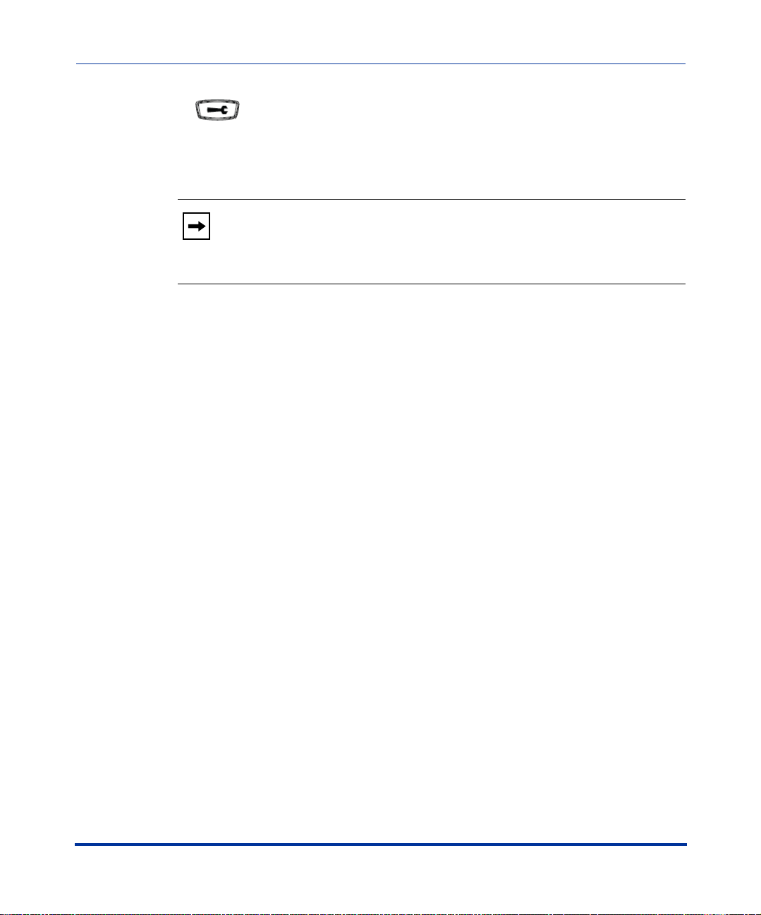
Options Key
The Options key allows you to access the "Options List" on the IP phone.
Accessible options in this list are for both user and administrator use. An
administrator must enter a password for administrator options.
Note: An administrator has the option of enabling and disabling the use
of password protection in the IP phone UI. This is configurable using the
configuration files only. For more information about this feature, see
Appendix A, the section “Password Settings” on page A-8.
This document describes the administrator options only. For a description of the
user options in the "Options List", see your model-specific SIP IP Phone User
Guide.
Configuration Interface Methods
2-4 41-001160-00, Rev 01 Release 2.0
Page 31

Configuration Interface Methods
IP Phone UI
The following illustration indicates the location of the Options Key on each phone
model.
53i
Configuration Interface Methods
Options Key
55i
Options Key
57i CT Handset
57i/57i CT
41-001160-00, Rev 01 Release 2.0 2-5
Page 32

IP Phone Administrator Guide
IP Phone UI
Using the Options Key
From the 53i, 55i, or 57i/57i CT:
Step Action
1 Press on the phone to enter the Options List.
2Use the r and s to scroll through the list of options.
3 To select an option, press the Show softkey, press 4, or select the number on the keypad that
corresponds to the option.
4Use the Change softkey to change a selected option.
5 Press the Done softkey at any time to save the changes and exit the current option.
6 Press the Cancel softkey, press
3, or press at any time to exit without saving changes.
From the 57i CT handset:
Step Action
1 Press the  key to enter the Options List when the phone is not in use.
2 Use the scroll keys  and Ï to scroll the options.
3 To select and change an option, press the
4 Press y when done.
r keys.
Configuration Interface Methods
2-6 41-001160-00, Rev 01 Release 2.0
Page 33

Configuration Interface Methods
Aastra Web UI
Aastra Web UI
Description
An administrator can setup and configure the IP phone using the Aastra Web UI.
The Aastra Web UI supports Internet Explorer and Gecko engine-based browsers
like Firefox, Mozilla or Netscape.
HTTP/HTTPS Support
The Aastra Web UI supports both Hypertext Transfer Protocol (HTTP) and
Hypertext Transfer Protocol over Secure Socket Layer (HTTPS) client and server
protocols.
HTTP is the set of rules for transferring files (text, graphic images, sound,
video, and other multimedia files) over the Internet. When you open your
Web browser, you are indirectly making use of HTTP. HTTP is an
application protocol that runs on top of the TCP/IP suite of protocols (the
foundation protocols for the Internet).
HTTPS is a Web protocol that encrypts and decrypts user page requests as well as
the pages that are returned by the Web server. HTTPS uses Secure Socket Layer
(SSL) or Transport Layer Security (TLS) as a sublayer under its regular HTTP
application layering.
security of a message transmission on the Internet. It uses a 40-bit key size
for the RC4 stream encryption algorithm, which is considered an adequate degree
of encryption for commercial exchange. TLS is a protocol that ensures privacy
between communicating applications and their users on the Internet. When a
server and client communicate, TLS ensures that no third party may eavesdrop or
tamper with any message. TLS is the successor to SSL.
Configuration Interface Methods
SSL is a commonly-used protocol for managing the
Note: HTTPS uses port 443 instead of HTTP port 80 in its interactions
with the TCP/IP lower layer.
41-001160-00, Rev 01 Release 2.0 2-7
Page 34

IP Phone Administrator Guide
Aastra Web UI
HTTP/HTTPS Client and Server Support
The Aastra IP phones allow for HTTP request processing and associated data
transfers to perform over a secure connection (HTTPS). The IP phones support
the following:
• Transfer of firmware images, configuration files, script files, and web page
content over a secure connection.
• Web browser phone configuration over a secure connection.
• TLS 1.0or SSL 3.0 methods for both client and server
HTTPS Client
When an HTTPS client opens and closes its TCP socket, the SSL software
respectively handshakes upon opening and disconnects upon closing from the
HTTPS server. The main HTTPS client functions are:
• Downloading of configuration files and firmware images.
• Downloading of script files based on an “HTTPS://” URL supplied by a
softkey definition.
HTTPS Server
The HTTPS server provides HTTP functionality over secure connections. It
coexists with the HTTP server but has its own set of tasks. The main HTTPS
server functions are:
• Delivery of web page content to a browser client over a secure connection.
• Execution of HTTP GET and POST requests received over a secure
Configuration Interface Methods
2-8 41-001160-00, Rev 01 Release 2.0
connection.
Page 35

Configuration Interface Methods
Aastra Web UI
Using HTTPS via the Aastra Web UI
HTTPS is enabled by default on the IP phones. When you open a browser window
and enter an IP address or host name for a phone using HTTP, a server redirection
occurs which automatically converts an HTTP connection to an HTTPS
connection. After the redirection, a “Security Alert” certificate window displays
alerting the user that information exchanged with the phone cannot be viewed or
changed by others. Accepting the certificate then forwards you to the phone’s Web
UI.
Notes:
1. The private key and certificate generate outside the phone and embed
in the phone firmware for use by the HTTPS server during the SSL
handshake.
2. Using the configuration files, the IP phone UI, or the Aastra Web UI,
you can configure the following regarding HTTPS:
- Specify HTTPS security client method to use (TLS 1.0 or SSL 3.0)
- Enable or disable HTTP to HTTPS server redirect function
- HTTPS server blocking of XML HTTP POSTS to the phone
Reference
Configuration Interface Methods
For more information on configuring the HTTPS protocol, see Chapter 4,
“Network Configuration of the IP Phones”, the sections:
• “Configuring the Configuration Server Protocol” on page 4-13
• “HTTPS Client/Server Configuration” on page 4-24
41-001160-00, Rev 01 Release 2.0 2-9
Page 36

Accessing the Aastra Web UI
Use the following procedure to access the Aastra Web UI.
Step Action
1 Open your web browser and enter the phone’s IP address or host name into the address field.
If the browser is using HTTP, the following redirect screen displays, followed by the “Security Alert”
window. This process redirects HTTP to use HTTPS for a more secure connection.
2 Click YES to accept the certificate.
Page 37

Configuration Interface Methods
Aastra Web UI
Step Action
3 At the prompt, enter your username and password and click .
The Network Status window displays for the IP phone you are accessing.
Note: For an administrator, the default user name is “admin” and the password is “22222”.
For a user, the default user name is “user” and the password field is left blank.
4 You can logout of the Aastra Web UI at any time by clicking LOGOFF.
The following illustration is an example of a Network Status screen for the 55i IP
phone.
IP address or
host name
55i Network
Status Window
Configuration Interface Methods
Logout button
The following categories display in the side menu of the Aastra Web UI: Status,
Operation, Basic Settings, Advanced Settings.
41-001160-00, Rev 01 Release 2.0 2-11
Page 38

IP Phone Administrator Guide
Aastra Web UI
Status
The Status section displays the network status and the MAC address of the IP
phone. It also displays hardware and firmware information about the IP phone.
The information in the Network Status window is read-only.
Operation
The Operation section provides the following options:
Heading Description
User Password Allows you to change user password.
Phone Lock Allows you to assign an emergency dial plan to the phone,
lock the phone to prevent any changes to the phone and to
prevent use of the phone, and reset the user password.
Programmable Keys 53i - 6 Top programmable keys (up to 6 programmable
functions)
55i - 6 Top programmable hard keys (up to 6 programmable
functions)
Softkeys and XML 55i - 6 Bottom programmable state-based softkeys (up to 20
programmable functions)
57i/57i CT - 6 Top programmable, static softkeys (up to 10
programmable functions; and 6 bottom programmable
state-based softkeys (up to 20 programmable functions)
Handset Keys
(57i CT only)
Directory Allows you to copy the Callers List and Directory List from
Configuration Interface Methods
Reset Allows you to restart the IP phone when required.
Allows you to configure up to 15 softkeys on the handset.
your IP phone to your PC.
2-12 41-001160-00, Rev 01 Release 2.0
Page 39

Configuration Interface Methods
Aastra Web UI
Basic Settings
The Basic Settings section provides the following options:
Heading Description
Preferences Allows you to set General specifications on the IP phone
Call Forward Allows you to set a phone number destination for where you
Advanced Settings
The Advanced Settings section provides the following options:
Heading Description
Network Allows you to set basic network settings such as, DHCP, IP
Global SIP Allows you to set basic and advanced global SIP settings,
Lines 1 through 9 Allows you to set SIP authentication settings, SIP network
Action URI Allows an administrator to specify a uniform resource
Configuration Server Allows you to set the protocol to use on the configuration
Configuration Interface Methods
such as, local dial plan, dial plan terminator, digit timeout,
park and pickup call settings, and enable/disable suppress
DTMF playback, display DTMF digits, play call waiting tone,
and stuttered dial tone. This section also allows you to set
intercom settings, map conference and redial keys, set ring
tones, set priority alerts, enable directed call pickup, set
time/date settings, and load language packs.
want calls forwarded.
address, DNS, Ethernet Port 0 and Port 1, and advanced
network settings such as, Network Address Translation
(NAT), time servers, and enable/disale HTTPS. The
Network subcategory also allows you to set Type of Service
(ToS)/Differentiated Services Code Point (DSCP), and
VLAN settings.
and Real-time Transport Protocol (RTP) settings that apply
to all lines on the IP phone.
settings, and RTP settings to use on a specific line.
identifier (URI) that triggers a GET when certain events
occur.
server (TFTP (default), FTP, HTTP, or HTTPS), configure
automatic firmware and configuration file updates, enable/
disable auto-resync, and assign an XML push server list.
41-001160-00, Rev 01 Release 2.0 2-13
Page 40

IP Phone Administrator Guide
Aastra Web UI
Heading Description
Firmware Update Allows you to manually perform a firmware update on the IP
phone from the configuration server.
Troubleshooting Allows you to perform troubleshooting tasks whereby the
results can be forwarded to Aastra Technical Support for
analyzing and troubleshooting
Enabling/Disabling the Aastra Web UI
The Aastra Web UI is enabled by default on the IP phones. A System
Administrator can disable the Aastra Web UI on a single phone or on all phones if
required using the configuration files. Use the following procedure to enable and
disable the Aastra Web UI.
To disable the Aastra Web UI:
Configuration Files
Step Action
1 Using a text-based editing application, open the <mac>.cfg file if you want to disable the Web UI on a
single phone. Open the aastra.cfg file to disable the Web UI on all phones
2 Enter the following parameter:
web interface enabled: 0
Note: A value of zero (0) disables the Web UI on the phone. A value of 1 enables the Web UI.
3 Save the changes and close the <mac>.cfg or the aastra.cfg file.
4 Restart the phone to apply the changes. The Aastra Web UI is disabled for a single IP phone or for all
Configuration Interface Methods
2-14 41-001160-00, Rev 01 Release 2.0
phones.
Page 41

About this chapter
Introduction
The IP phones provide specific options on the IP Phone UI that allow an
administrator to change or set features and configuration information as required.
For all models, you can also use the Aastra Web UI and the configuration files to
enter and change values.
Note: Specific options are configurable only via the IP Phone UI, and/or
Aastra Web UI, and/or configuration files. See Chapter 4, “Network
Configuration of the IP Phones” for more information about configuring
each option.
Chapter 3
Administrator Options
Administrator Options
This chapter provides information about the Administrator options.
Topics
This chapter covers the following topics:
Topi c Page
Administrator Level Options page 3-3
IP Phone UI Options page 3-3
Aastra Web UI Options page 3-4
Configuration File Options page 3-4
Phone Status page 3-6
Basic Preferences (Aastra Web UI) page 3-10
Network page 3-12
Line Settings page 3-20
41-001160-00, Rev 01 Release 2.0 3-1
Page 42

IP Phone Administrator Guide
About this chapter
Topi c Page
Configuration Server Settings page 3-23
Firmware Update Features page 3-25
Administrator Options
3-2 41-001160-00, Rev 01 Release 2.0
Page 43

Administrator Options
Administrator Level Options
Administrator Level Options
Description
There are specific options available only to an Administrator on the IP phones.
For the IP Phone UI, you can access the Administrator options via the “Options
List” using a default password of "22222".
Note: An administrator has the option of enabling and disabling the use
of password protection in the IP phone UI. This is configurable using the
configuration files only. For more information about this feature, see
Appendix A, the section “Password Settings” on page A-8.
For the Aastra Web UI, you can access the Administrator options by entering a
user name and password. The default user name is "admin" and the default
password is "22222".
IP Phone UI Options
The following are administrator options in the "Options List" on the IP phone UI:
Administrator Options
• Phone Status->Factory Default
• Network
• SIP Settings
Reference
For information about all other user options in the “Options List”, see your
model-specific SIP IP Phone User Guide.
For procedures on configuring the IP phone via the IP phone UI, see Chapter 4,
“Network Configuration of the IP Phones.”
41-001160-00, Rev 01 Release 2.0 3-3
Page 44

IP Phone Administrator Guide
Administrator Level Options
Aastra Web UI Options
The following are administrator options in the Aastra Web UI:
• Restore to Factory Defaults
• Basic Settings (Local Dial Plan, Dial PlanTerminator, Digit Timeout,
Outgoing Intercom Settings, Key Mapping, Ring Tones, Priority Alert,
Directed Call Pickup)
• Network
• Global SIP
• Line Settings
• Configuration Server
•Firmware Update
• Troubleshooting
Reference
For information about all other user options, see your model-specific
Administrator Options
SIP IP Phone User Guide.
For procedures on configuring the IP phone via the Aastra Web UI, see Chapter 4,
“Network Configuration of the IP Phones.”
Configuration File Options
A system administrator can enter specific parameters in the configuration files to
configure the IP phones. All parameters in configuration files can only be set by
an administrator.
Reference
For a description of each configuration file parameter, see Appendix A,
“Configuration Parameters.”
3-4 41-001160-00, Rev 01 Release 2.0
Page 45

Administrator Options
Administrator Level Options
Using the Configuration Files
When you use the configuration files to configure the IP phones, you must use a
text-based editing application to open the configuration file (aastra.cfg or
<mac>.cfg).
Use the following procedure to add, delete, or change parameters and their
settings in the configuration files.
Note: Apply this procedure wherever this Administrator Guide refers to
configuring parameters using the configuration files.
Configuration files
Step Action
1 Using a text-based editing application, open the configuration file for the phone, for which you want to
configure the directory list (either aastra.cfg, <mac>.cfg or both).
2 Enter the required configuration parameters followed by the applicable value. For example,
Administrator Options
directory 1: company_directory
directory 2: my_personal_directory
3 Save the changes and close the configuration file.
4 If the parameter requires the phone to be restarted in order for it to take affect, use the
IP Phone UI or the Aastra Web UI to restart the phone.
41-001160-00, Rev 01 Release 2.0 3-5
Page 46

IP Phone Administrator Guide
Administrator Level Options
Phone Status
The Phone Status on the IP Phone displays the network status and firmware
version of the IP phone. This option also allows you to restart the phone, and set
the phone to factory defaults.
You can display phone status and reset the phone using the IP phone UI or the
Aastra Web UI.
Phone Status via IP Phone UI
In the IP phone UI, the Phone Status options are available to the user and the
administrator and do not require a password entry. However, the "Factory
Default" option is for administrator use only.
The following information displays for phone status on the IP phone UI:
Phone Status Screen for 53i Phone
Phone Status
1. Network Port 1
2. Network Port 2
Administrator Options
2. Firmware Version
3. Restart Phone
4. Restore Defaults
=Next
=Enter
Phone Status Screen for 55i, 57i, and 57i CT Phones
Phone Status
1. Network Status
2. Firmware Version
3. Restart Phone
4. Factory Default
Show
Done
3-6 41-001160-00, Rev 01 Release 2.0
Page 47

Administrator Options
Administrator Level Options
• Network Port 1 (53i)
Displays the IP address on Port 1 of the phone.
• Network Port 2 (53i)
Displays the IP address on Port 2 of the phone.
• Network Status (55i, 57i, and 57i CT)
Displays the network status of the Ethernet ports at the back of the phone. You
can also view the phone’s IP and MAC addresses. These fields are read-only.
• Firmware Version
Displays information about the firmware that is currently installed on the IP
phone.
• Restart Phone
This option lets you reboot the phone. A reset may be necessary when:
- There is a change in your network, OR
- To re-load modified configuration files, OR
- If the settings for the IP phone on the IP PBX system have been modified.
• Restore Defaults (53i) or Factory Default (55i, 57i, 57i CT) (admin only)
This option lets you reset the phone to its factory default settings. There are
two options in setting the factory defaults on the IP phone:
Administrator Options
-All Defaults
-Config Default
The "All Defaults" option resets the factory defaults for all of the settings in
the aastra.cfg, <mac>.cfg, and local configuration. Performing this option
results in losing all user-modified settings.
The "Config Default" option resets the settings on the local IP phone
configuration only.
41-001160-00, Rev 01 Release 2.0 3-7
Page 48

IP Phone Administrator Guide
Administrator Level Options
Phone Status via Aastra Web UI
In the Aastra Web UI, the "Network Attributes", "Hardware Information", and
"Firmware Information" options are read only and available for viewing by the
user and administrator. Resetting the IP phone to factory defaults using the Aastra
Web UI (Operation->Reset->Current Settings) is available to the administrator
only.
Administrator Options
The following information displays for phone status in the Aastra Web UI at the
location Status->System Information. This information is available to the user
and the administrator as read-only.
• Network Attributes
Displays the network status of the Ethernet ports at the back of the phone. You
can also view the phone’s IP and MAC addresses. Information in this field
includes Link State, Negotiation, Speed, and Duplex for Port 0 and Port 1.
• Hardware Information
Displays the current IP phone platform and the revision number.
• Firmware Information
Displays information about the firmware that is currently installed on the IP
phone. Information in this field includes Firmware Version, Firmware Release
Code, Boot Version, Release Date/Time.
3-8 41-001160-00, Rev 01 Release 2.0
Page 49

Administrator Options
Administrator Level Options
• Factory Default Feature
A user and administrator can restart the phone at Operation->Reset->Phone.
However, only an administrator has access to restoring factory defaults to the
IP phone at Operation->Reset->Current Settings.
There are two options for setting factory defaults using the Aastra Web UI:
- Restore to Factory Defaults
- Remove Local Configuration Settings
The "Restore to Factory Defaults" option resets the factory defaults for all of
the settings in the aastra.cfg, <mac>.cfg, and local configuration. Performing
this option results in losing all user-modified settings.
The "Remove Local Configuration Settings" option resets the settings on
the local IP phone configuration only.
Reference
Administrator Options
For procedures in setting factory defaults, see Chapter 9, “Troubleshooting.”
41-001160-00, Rev 01 Release 2.0 3-9
Page 50

Basic Preferences (Aastra Web UI)
An administrator can configure the following basic preferences using the Aastra
Web UI:
• General Preferences
— Local Dial Plan
A dial plan that describes the number and pattern of digits that a user dials
to reach a particular telephone number.
— Dial Plan Terminator
A dial plan terminator or timeout. When you configure the IP phone to
use a dial plan terminator (such as the pound symbol (#)) the phone waits
4 or 5 seconds after you pick up the handset or press a key to make a call.
— Digit Timeout
Represents the time, in seconds, to configure the timeout between
consecutive key presses.
— Park Call (users and admin)
The parking of a live call to a specific extension. This feature on the Basic
Preferences screen is available on the 55i, 57i, and 57i CT only.
— Pickup Parked Call (users and admin)
Picking up a parked call at the specified extension. This feature on the
Basic Preferences screen is available on the 55i, 57i, and 57i CT only.
— Suppress DTMF Playback (users and admin)
Enables and disables suppression of DTMF playback when a number is
dialed from the softkeys or programmable keys.
— Display DTMF Digits (users and admin)
Enables and disables the display of DTMF digits on the IP phone display
during a connected state.
— Play Call Waiting Tone (users and admin)
Enable or disables the playing of a call waiting tone when a caller is on an
active call and a new call comes into the phone.
— Stuttered Dial Tone (users and admin)
Enable or disables the playing of a stuttered dial tone when there is a
message waiting on the IP phone.
Page 51

Administrator Options
Administrator Level Options
• Incoming/Outgoing Intercom Calls
Specifies whether the IP phone or the server is responsible for notifying the
recipient that an Intercom call is being placed. Also specifies the prefix code
for server-side Intercom calls, and specifies the configuration to use when
making the Intercom call.
Note: Users and administrators can configure incoming Intercom calls
on all phones. Only administrators can configure outgoing Intercom calls
on the 55i, 57i, and 57i CT.
• Key Mapping
Allows you to set the Redial and/or Conf keys as speedial keys.
• Ring Tones (user and admin)
Allows you to set ring tones and ring tone sets.
• Priority Alerting
Enabling/disabling priority alert by setting specific ring tones for types of
calls (Group, External, Internal, Emergency, Priority).
• Directed Call Pickup
Enabling/disabling of directed call pickup feature and the playing of a ring
tone splash.
Administrator Options
•Time and Date (user and admin)
Allows you to set time and date formats for the IP phone.
• Language (user and admin)
Allows you to set the language to display on the IP phones and the Aastra
Web UI by loading the applicable language pack.
References
For more information about each of these features, see Chapter 5, “Operational IP
Phone Features.”
41-001160-00, Rev 01 Release 2.0 3-11
Page 52

IP Phone Administrator Guide
Administrator Level Options
Network
The following paragraphs describe the network parameters you can configure on
the IP phone. Network settings are in two categories:
• Basic network settings
• Advanced network settings
Note: Specific parameters are configurable using the Aastra Web UI only
and are indicated where applicable.
Basic Network Settings
If Dynamic Host Configuration Protocol (DHCP) is enabled, the IP phone
automatically configures all of the Network settings. If the phone cannot populate
the Network settings, or if DHCP is disabled, you can set the Network options
manually.
• DHCP
Enables or disables DHCP. When enabled, the phone may populate the
Administrator Options
following fields as read-only: IP Address, Subnet Mask, Gateway, Broadcast
Address, Domain Name
Servers (DNS), Trivial File Transfer Protocol (TFTP) Server, and Timer
Servers.
Note: For DHCP to automatically populate the IP address or qualified
domain name for the TFTP server, your DHCP server must support
Option 66. For more information, see Chapter 4, the section, “DHCP” on
page 4-4.
• IP Address
IP address of the IP phone. To assign a static IP address, disable DHCP.
• Subnet Mask
Subnet mask defines the IP address range local to the IP phone. To assign a
static subnet mask, disable DHCP.
• Gateway
The IP address of the network’s gateway or default router IP address. To
assign a static Gateway IP address, disable DHCP.
3-12 41-001160-00, Rev 01 Release 2.0
Page 53

Administrator Options
Administrator Level Options
• Primary DNS
Primary Domain Name Service. A service that translates domain names into
IP addresses. To assign static DNS addresses, disable DHCP.
• Secondary DNS
Secondary Domain Name Service. A service that translates domain names
into IP addresses. To assign static DNS addresses, disable DHCP.
Note: If a host name is configured on the IP phone, you must also set a
DNS.
• Ethernet Port 0
Sets the negotiation method on Ethernet Port 0. Default is Auto-negotiation.
• Ethernet Port 1
Sets the negotiation method on Ethernet Port 1. Default is Auto-negotiation.
Advanced Network Settings
• NAT IP
Network Address Translator settings are used to map your firewall to an
external NAT device. This is the IP address of the external network device
that enforces NAT. Default is 0.0.0.0.
Administrator Options
• NAT SIP Port
Hard-coded port number of the external network device that enforces NAT
SIP. Default is 51620.
• NAT RTP Port
Hard-coded port number of the external network device that enforces NAT
RTP. Default is 51720.
• Nortel NAT Traversal Enabled
Enables or disables the phone to operate while connected to a network device
that enforces NAT. Valid values are 0 (No) or 1 (Yes). Default is 0 (No).
• Nortel NAT Timer (seconds)
The interval, in seconds, that the phone sends SIP ping requests to the Nortel
proxy. Default is 30.
41-001160-00, Rev 01 Release 2.0 3-13
Page 54

IP Phone Administrator Guide
Administrator Level Options
• NTP Time Servers
Enables or disables the time server. This parameter affects time server1, time
server2, and time server3. Valid values are 0 (enable) and 1 (disable). Default
is 1 (disable).
• Time Server 1, 2, and 3
The primary, secondary, and tertiary time server's IP address or qualified
domain name. If the "NTP Time Server" parameter is enabled, and the
primary and secondary time servers are not configured or cannot be accessed,
the value for Time Server 3 is used to request the time.
• HTTPS Client Method
Defines the security method that the client advertises to the server during the
Secure Socket Layer (SSL) handshake. Valid values are SSL 3.0 and TLS 1.0.
Default is SSL 3.0.
• HTTPS Server - Redirect HTTP to HTTPS
Allows or disallows redirection from the HTTP server to the HTTPS server
• HTTPS Server - Block XML HTTP POSTs
Enables or disables the blocking of XML scripts from HTTP POSTs.
Administrator Options
3-14 41-001160-00, Rev 01 Release 2.0
Type of Service (ToS), DSCP
Network settings also allows you to set Type of Service (ToS) and Differentiated
Services Code Point (DSCP).
Reference
For more information about ToS and DSCP see Chapter 4, the section, “Type of
Service (ToS), Quality of Service (QoS), and DiffServ QoS” on page 4-32.
VLAN
You can enable or disable VLAN and set specific VLAN IDs and priorities under
Network Settings.
Reference
For more information about VLAN, see Chapter 4, the section, “Virtual LAN
(optional)” on page 4-31.
Page 55

Administrator Options
Administrator Level Options
SIP Settings
The following paragraphs describe the SIP parameters you can configure on the IP
phone. SIP configuration consists of configuring:
• Basic SIP Authentication Settings
• Basic SIP Network Settings
• Advanced SIP settings
• RTP Settings
Note: Specific parameters are configurable using the Aastra Web UI only
and are indicated where applicable. If you have a proxy server or have a
SIP registrar present at a different location than the PBX server, the SIP
parameters may need to be changed. The SIP parameters can be set on a
global or per-line basis.
Basic SIP Authentication Settings
Administrator Options
• Screen Name
Name that displays on the idle screen. Valid values are up to 20 alphanumeric
characters. Configurable on a global and per-line basis.
• Phone Number
(User Name in IP phone UI and configuration files) User name used in the
name field of the SIP URI for the IP phone and for registering the phone at the
registrar. Valid values are up to 20 alphanumeric characters. Configurable on
a global and per-line basis.
• Caller ID
(Display Name in IP phone UI and configuration files). Name used in the
display name field of the "From SIP" header field. Some IP PBX systems use
this as the caller’s ID, and some may overwrite this with the string that is set
at the PBX system. Valid values are up to 20 alphanumeric characters.
Configurable on a global and per-line basis.
• Authentication Name
Authorization name used in the username field of the Authorization header
field of the SIP REGISTER request. Valid values are up to 20 alphanumeric
characters. Configurable on a global and per-line basis.
41-001160-00, Rev 01 Release 2.0 3-15
Page 56

IP Phone Administrator Guide
Administrator Level Options
• Password
Password used to register the IP phone with the SIP proxy. Valid values are up
to 20 alphanumeric characters. Passwords are encrypted and display as
asterisks when entering. Configurable on a global and per-line basis.
• BLA Number
(not configurable via IP phone UI) Phone number that you assign to BLA
lines that is shared across all phones (global configuration) or shared on a
per-line basis (per-line configuration). For more information about BLA, see
Chapter 5, the section, “Bridged Line Appearance (BLA) (57i/57i CT/53i
only)” on page 5-67.
• Line Mode
(Sip Mode in configuration files. Not configurable in IP phone UI). The
mode-type that you assign to the IP phone on a global or per-line basis. Valid
values are Generic (0), BroadSoft SCA (1), Nortel (2), or BLA (3). Default is
Generic (0).
Basic SIP Network Settings
• Proxy Server
Administrator Options
3-16 41-001160-00, Rev 01 Release 2.0
(Proxy IP in the configuration files). IP address of the SIP proxy server. Up to
64 alphanumeric characters. Configurable on a global and per-line basis.
• Proxy Port
SIP proxy server’s port number. Default is 0. Configurable on a global and
per-line basis.
• Backup Proxy Server
The IP address of the backup SIP proxy server for which the IP phone uses
when the primary SIP proxy is unavailable.
• Backup Proxy Port
The backup proxy’s port number.
• Outbound Proxy Server
Address of the outbound proxy server. All SIP messages originating from the
phone are sent to this server. For example, if you have a Session Border
Controller in your network, then you would normally set its address here.
Default is 0.0.0.0. Configurable on a global and per-line basis.
Page 57

Administrator Options
Administrator Level Options
• Outbound Proxy Port
The proxy port on the proxy server to which the IP phone sends all SIP
messages. Default is 0. Configurable on a global and per-line basis.
• Registrar Server
(Registrar IP in the configuration files). IP address of the SIP registrar. Up to
64 alphanumeric characters. Enables or disables the phone to be registered
with the Registrar. When Register is disabled globally, the phone is still active
and you can dial using username and IP address of the phone. A message "No
Service" displays on the idle screen and the LED is steady ON. If Register is
disabled for a single line, no messages display and LEDs are OFF.
Configurable on a global and per-line basis.
• Registrar Port
SIP registrar’s port number. Default is 0. Configurable on a global and
per-line basis.
• Backup Registrar Server
The address of the backup registrar (typically, the backup SIP proxy) for
which the IP phone uses to send REGISTER requests if the primary registrar is
unavailable.
Administrator Options
• Backup Registrar Port
The backup registrar's (typically the backup SIP proxy) port number.
• Registration Period
(Not configurable via IP Phone UI). The requested registration period, in
seconds, from the registrar. Configurable on a global and per-line basis.
Advanced SIP Settings
In addition to the basic SIP settings, you can also configure the following
advanced SIP parameters. These parameters are not configurable via the IP phone
UI.
• Explicit MWI Subscription
If the IP phone has a message waiting subscription with the Service Provider,
a Message Waiting Indicator (MWI) (LED or display icon) tells the user there
is a message on the IP Phone. You can enable and disable MWI by setting this
parameter to 0 (disable) or 1 (enable) in the configuration files or by checking
the box for this field in the Aastra Web UI. Default is disabled.
41-001160-00, Rev 01 Release 2.0 3-17
Page 58

IP Phone Administrator Guide
Administrator Level Options
• Explicit MWI Subscription Period
The requested duration, in seconds, before the MWI subscription times out.
The phone re-subscribes to MWI before the subscription period ends.
• Send MAC Address in REGISTER Message
Adds an "Aastra-Mac:" header to the SIP REGISTER messages sent from the
phone to the call server, where the value is the MAC address of the phone.
• Send Line Number in REGISTER Message
Adds an "Aastra-Line:" header to the SIP REGISTER messages sent from the
phone to the call server, where the value is the line number that is being
registered.
• Session Timer
The time, in seconds, that the IP phone uses to send periodic re-INVITE
requests to keep a session alive. The proxy uses these re-INVITE requests to
maintain the status' of the connected sessions. See RFC4028 for details.
Default is 0.
• Timer 1 and Timer 2
The time, in milliseconds, that applies to an IP phone session. These timers
are SIP transaction layer timers defined in RFC 3261. Timer 1 is an estimate
Administrator Options
of the round-trip time (RTT). Timer 2 represents the amount of time a
non-INVITE server transaction takes to respond to a request.
• Transaction timer
The amount of time, in
milliseconds that the phone allows the callserver (registrar/proxy) to respond
to SIP messages that it sends. If the phone does not receive a response in the
amount of time designated for this parameter, the phone assumes the message
has timed out. Valid values are 4000 to 64000. Default is 4000.
• Transport Protocol
The protocol that the RTP port on the IP phone uses to send out RTP packets.
Valid values are 0 (both), 1 (UDP), or 2 (TCP). Default is 1 (UDP).
• Registration Failed Retry Timer
Specifies the time, in seconds, that the phone waits between registration
attempts when a registration is rejected by the registrar.
• Registration Timeout Retry Timer
Specifies the length of time, in seconds, that the phone waits until it
re-attempts to register after a REGISTER message times out.
3-18 41-001160-00, Rev 01 Release 2.0
Page 59

Administrator Options
Administrator Level Options
• Registration Renewal Timer
The length of time, in seconds, prior to expiration, that the phone renews
registrations.
• BLF Subscription Period
Specifies the time period, in seconds, that the BLF feature becomes active
again after a software/firmware upgrade or after a reboot of the IP phone.
RTP Settings
You can configure the following RTP settings:
•RTP Port
• Basic Codecs (G.711 u-Law, G.711 a-Law, G.729)
(not configurable via IP phone UI). Enables or disables basic codecs.
Enabling this parameter allows the IP phone to use the basic Codecs when
sending/receiving RTP packets. Valid values are 0 (disabled) and 1 (enabled).
Default is 0 (disabled).
• Force RFC2833 Out-of-Band DTMF
(not configurable via IP phone UI). Enables or disables out-of-band DTMF.
Enabling this parameter forces the IP phone to use out-of-band DTMF
according to RFC283. Valid values are 0 (disabled) and 1 (enabled). Default is
1 (enabled).
• Customized Codec Preference List
(not configurable via IP phone UI). Specifies a customized Codec preference
list which allows you to use the preferred Codecs for this IP phone. For valid
values, see Appendix A, the section, “RTP, Codec, DTMF Global Settings” on
page A-63.
• DTMF Method
(not configurable via IP phone UI). Sets the dual-tone multifrequency
(DTMF) method to use on the IP phone on a global or per-line basis. Valid
values are 0 (RTP), 1 (SIP INFO), or 2 (BOTH). Default is 0 (RTP).
Configurable on a global and per-line basis.
• Silence Suppression
Enables or disables the phone to use the negotiated silence suppression
setting.
Administrator Options
41-001160-00, Rev 01 Release 2.0 3-19
Page 60

IP Phone Administrator Guide
Administrator Level Options
Line Settings
An administrator can configure multiple lines on the IP phone with the same SIP
network configuration (global) or a different SIP network configuration (per-line).
The following table provides the number of lines available for each IP phone
model.
IP Phone
Model
53i 9
55i 9
57i 9
57i CT 9
Available
Lines
For more information about configuring lines on the IP phone, see Appendix A,
the section, “SIP Basic, Per-Line Settings” on page A-48 and “DTMF Per-Line
Settings” on page A-65.
Administrator Options
3-20 41-001160-00, Rev 01 Release 2.0
Page 61

Administrator Options
Administrator Level Options
Softkeys/Programmable Keys
A user or administrator can assign a line to a specific softkey or programmable
key (53i has programmable keys only). The available softkeys also depend on the
IP phone model as shown in the following table.
IP Phone Model Softkeys
53i - - 6
55i 6 36 to 108*
57i 12 36 to 108*
57i CT 12 36 to 108* on Base
*The 536EM expansion module consists of 36 softkeys. You can have up to 3 expansion modules on an IP
phone totaling 108 softkeys. Valid for 55i, 57i, and 57i CT phones.
**The 560EM expansion module consists of 60 softkeys. You can have up to 3 expansion modules on an IP
phone totaling 180 softkeys. Valid for 57i and 57i CT phones only.
Additional Softkeys
with Expansion
Module Programmable Keys
(Model 536EM)
(Model 536EM)
60 to 180**
(Model 560EM)
Station
(Model 536EM)
60 to 180** on Base
Station
(Model 560EM)
Administrator Options
6
-
-
The softkey or programmable key can be set to use a specific function. Available
functions depend on the IP phone model.
41-001160-00, Rev 01 Release 2.0 3-21
Page 62

The functions you can configure are:
• none
• line
• speeddial
• do not disturb
•BLF
• BLF/List
•XML
• flash
• sprecode
•park
•pickup
• last call return
• directory
• callers list
• intercom
• services
•empty
References
For information about configuring softkeys, see Chapter 5, the section, “Softkeys/
Programmable Keys/Feature Keys” on page 5-21.
For more information about softkey functions see Appendix A, the section,
“Softkey/Programmable Key/Feature Key Parameters” on page A-108.
Page 63

Administrator Options
Administrator Level Options
Configuration Server Settings
The configuration server stores the firmware images, configuration files, and
software when performing software upgrades to the IP phone. An administrator
can configure the following parameters for the configuration server:
• Download Protocol
Protocol to use for downloading new versions of firmware and configuration
files to the IP phone. Valid values are TFTP, FTP, and HTTP. Default is TFTP.
• TFTP Server
IP address or qualified domain name of the TFTP server. You can select a
primary or alternate TFTP server and then assign an IP address or qualified
domain name to your selection. Set this option if TFTP is the download
protocol selected.
Note: For DHCP to automatically populate the IP address or domain
name for the TFTP server, your DHCP server must support Option 66.
For more information, see Chapter 4, the section, “DHCP” on page 4-4.
• FTP Server
IP address or network host name of the FTP server. If required, you can also
assign a user name and password for access to the FTP server. Set this option
if FTP is the download protocol selected. If you enter a network host name,
DNS must also be set.
Administrator Options
• HTTP Server
IP address of the HTTP server. You can also assign an HTTP path to the
HTTP server. Set this option if HTTP is the download protocol selected.
• HTTPS Server
IP address of the HTTPS server. You can also assign an HTTPS path to the
HTTPS server. Set this option if HTTPS is the download protocol selected.
41-001160-00, Rev 01 Release 2.0 3-23
Page 64

IP Phone Administrator Guide
Administrator Level Options
• Mode
(not configurable via IP phone UI). Enables and disables the IP phone to be
updated automatically (auto-resync) once a day at a specific time in a 24-hour
period. Updating can be done to the configuration files only, the firmware
only, or both. This feature works with TFTP, FTP, and HTTP servers. The
auto update feature works with both encrypted and plain text configuration
files.
Note: Any changes made using the Aastra Web UI or the IP phone UI are
not overwritten by an auto-resync update. Auto-resync affects the
configuration files only. However, the settings in the Aastra Web UI take
precedence over the IP phone UI and the configuration files.
• Time (24-hour)
(Not configurable via IP phone UI). Sets the time of day in a 24-hour period
for the IP phone to be automatically updated (auto-resync). This parameter
works with TFTP, FTP, and HTTP servers.
Note: Auto-Resync adds up to 15 minutes random time to the configured
time. For example, if the auto resync time parameter is set to 02:00, the
event takes place any time between 02:00 and 02:15.
Administrator Options
• XML Push Server List
(not configurable via IP phone UI). The HTTP server that is pushing XML
applications to the IP phone.
Reference
For more information about configuring the configuration server, see Chapter 4,
the section, “Configuration Server Protocol” on page 4-13.
3-24 41-001160-00, Rev 01 Release 2.0
Page 65

Administrator Options
Administrator Level Options
Firmware Update Features
The IP phone uses a TFTP, FTP, HTTP, or HTTPS server (depending on the
protocol configured on the IP phone) to download configuration files and
firmware.
You can download the firmware stored on the configuration server in one of three
ways:
• Manual firmware update using the Aastra Web UI (TFTP only).
• Manual update of firmware and configuration files (by restarting the phone
via the IP phone UI or the Aastra Web UI).
• Automatic update of firmware, configuration files, or both at a specific time
in a 24-hour period (via the Aastra Web UI or configuration files)
Reference
For more information about firmware update, see Chapter 8, “Firmware
Upgrade.”
Administrator Options
41-001160-00, Rev 01 Release 2.0 3-25
Page 66

IP Phone Administrator Guide
Administrator Level Options
Administrator Options
3-26 41-001160-00, Rev 01 Release 2.0
Page 67

About this chapter
Introduction
This chapter provides the information required to configure the administrative
options on the IP phones. It includes procedures for configuring via the
configuration files, the IP Phone UI, and the Aastra Web UI where applicable.
Topics
Chapter 4
Configuring the IP Phones
Network Configuration
of the IP Phones
This chapter covers the following topics:
Topi c Page
Overview page 4-3
Basic Network Settings page 4-4
DHCP page 4-4
Configuring Network Settings Manually page 4-7
Configuration Server Protocol page 4-13
Configuring the Configuration Server Protocol page 4-13
Advanced Network Settings page 4-18
Network Address Translation (NAT) page 4-18
Configuring Nortel NAT (optional) page 4-20
Configuring NAT Address and Port (optional) page 4-22
HTTPS Client/Server Configuration page 4-24
41-001160-00, Rev 01 Release 2.0 4-1
Page 68

IP Phone Administrator Guide
About this chapter
Topi c Page
Universal Plug and Play (UPnP) (for remote phones) page 4-28
Virtual LAN (optional) page 4-31
Type of Service (ToS), Quality of Service (QoS), and DiffServ QoS page 4-32
Network Time Servers page 4-41
Session Initiation Protocol (SIP) Settings page 4-43
Real-time Transport Protocol (RTP) Settings page 4-56
Configuring the IP Phones
4-2 41-001160-00, Rev 01 Release 2.0
Page 69

Network Configuration of the IP Phones
Overview
Overview
An administrator can configure the IP Phone Network and SIP options from the
phone UI, from the Aastra Web UI, or the configuration files. Administrator level
options are password protected in both the IP phone UI and the Aastra Web UI.
The procedures in this section include configuring from the IP phone UI and the
Aastra Web UI. To configure the IP phones using the configuration files, see
Appendix A, “Configuration Parameters.”
To configure the phone using the IP phone UI, you must enter an administrator
password. To configure the phone using the Aastra Web UI, you must enter an
administrator user name and password.
Configuring the IP Phones
Note: An administrator has the option of enabling and disabling the use
of password protection in the IP phone UI. This is configurable using the
configuration files only. For more information about this feature, see
Appendix A, the section “Password Settings” on page A-8.
Note: In the IP phone UI, the default password is "22222". In the
Aastra Web UI, the default admin user name is "Admin" and the default
password is "22222".
References
For configuring the IP phone at the Asterisk IP PBX, see Appendix C,
“Configuring the IP Phone at the Asterisk IP PBX.”
For sample configuration files, see Appendix D, “Sample Configuration Files.”
These sample files include basic parameters required to register the IP phone at
the PBX.
41-001160-00, Rev 01 Release 2.0 4-3
Page 70

IP Phone Administrator Guide
Basic Network Settings
Basic Network Settings
This section describes the basic network settings on the IP phone which include
configuring for:
• DHCP
• IP Address (of phone)
• Subnet Mask (of phone)
• Gateway
• Primary DNS
• Secondary DNS
• Ethernet Port 0
• Ethernet Port 1
DHCP
The IP phone is capable of querying a DHCP server, allowing a network
administrator a centralized and automated method of configuring various network
parameters for the phone. If DHCP is enabled, the IP phone requests the following
Configuring the IP Phones
4-4 41-001160-00, Rev 01 Release 2.0
network information:
• Subnet Mask
• Gateway (i.e. router)
• Domain Name Server (DNS)
• Broadcast Address
• Network Time Protocol Server
• IP Address
• TFTP Server Name
Page 71

Network Configuration of the IP Phones
Basic Network Settings
Note: For DHCP to automatically populate the IP address or domain
name for the TFTP server, your DHCP server must support Option 66.
Option 66 is responsible for forwarding the TFTP server IP address or
domain name to the phone automatically. If your DHCP server does not
support Option 66, you must manually enter the IP address or domain
name for the TFTP server into your IP phone configuration.
The network administrator chooses which of these parameters (if any) are
supplied to the IP phone by the DHCP server. The administrator must configure
the phone manually to provide any required network parameters not supplied by
the DHCP server.
Configuring DHCP
You can enable and disable DHCP using the configuration files, the IP phone UI,
or the Aastra Web UI.
Configuring the IP Phones
Configuration Files
For specific parameters you can set in the configuration files, see Appendix A, the section, “Network
Settings” on page A-5.
IP Phone UI
Step Action
1 Press on the phone to enter the Options List.
2Select Network.
3 Select option DHCP.
4 Press Change to set "Use DHCP" to "Yes" (enable) or "No" (disable).
5 Press Done to save the changes.
41-001160-00, Rev 01 Release 2.0 4-5
Page 72

IP Phone Administrator Guide
Basic Network Settings
.
Aastra Web UI
Step Action
1 Click on Advanced Settings->Network->Basic Network Settings.
2 Enable the "DHCP" field by checking the check box. (Disable this field by unchecking the box).
3 Click to save your settings.
Configuring the IP Phones
4-6 41-001160-00, Rev 01 Release 2.0
Page 73

Network Configuration of the IP Phones
Basic Network Settings
Configuring Network Settings Manually
If you disable DHCP on your phone, you need to configure the following network
settings manually:
• IP Address
• Subnet Mask
• Gateway
• Primary DNS
• Secondary DNS
You can configure the network settings using the configuration files, the IP phone
UI, or the Aastra Web UI.
Configuration Files
For specific parameters you can set in the configuration files, see Appendix A, the section, “Network
Settings” on page A-5.
Configuring the IP Phones
IP Phone UI
Step Action
1 Press on the phone to enter the Options List.
2Select Network.
3Select IP Address and enter the IP address of the phone.
4Select Subnet Mask and enter the subnet mask.
5Select Gateway and enter the gateway address.
6Select DNS and enter a Primary and/or Secondary DNS server.
7 Press Done to save the changes.
The IP phone is manually configured.
You can now continue configuring the IP phone if required using the IP Phone UI.
41-001160-00, Rev 01 Release 2.0 4-7
Page 74

IP Phone Administrator Guide
Basic Network Settings
.
Aastra Web UI
Step Action
1 Click on Advanced Settings->Network->Basic Network Settings.
2 Enter an IP address of the phone in the IP Address field.
3 Enter a subnet mask in the Subnet Mask field.
4 Enter a gateway address in the Gateway field.
Configuring the IP Phones
5 Enter a Primary DNS in the Primary DNS field, and/or a secondary DNS in the Secondary DNS
field.
6 Click to save your settings.
The IP phone is manually configured.
You can now continue configuring the IP phone if required using the Aastra Web UI.
4-8 41-001160-00, Rev 01 Release 2.0
Page 75

Network Configuration of the IP Phones
Basic Network Settings
Configuring Ethernet Ports 0 and 1 Negotiation
Ethernet is the computer networking technology for local area networks (LANs).
You use the Ethernet ports to connect to a LAN using a twisted pair 10BASE-T
cable to transmit 10BASE-T Ethernet.
There are two Ethernet ports on the rear of the IP phones, Ethernet Port 0 and
Ethernet Port 1. Using the Aastra Web UI, you can select the type of transmission
you want these ports to use to communicate over the LAN. The IP phones support
each of the following methods of transmission:
• Auto-negotiation
• Half-duplex (10Mbps or 100 Mbps)
• Full-duplex (10Mbps or 100Mbps)
Auto-negotiation
Auto-negotiation is when two connected devices choose common transmission
parameters. In the auto-negotiation process, the connected devices share their
speed and duplex capabilities and connect at the highest common denominator
(HCD). Auto-negotiation can be used by devices that are capable of different
transmission rates (such as 10Mbit/sec and 100Mbit/sec), different duplex modes
(half duplex and full duplex) and/or different standards at the same speed. You can
set the Ethernet ports on the IP phones to auto-negotiate during transmission.
Configuring the IP Phones
Half-Duplex (10Mbps or 100Mbps)
Half-duplex data transmission means that data can be transmitted in both
directions on a signal carrier, but not at the same time. For example, on a LAN
using a technology that has half-duplex transmission, one device can send data on
the line and then immediately receive data on the line from the same direction in
which data was just transmitted. Half-duplex transmission implies a bidirectional
line (one that can carry data in both directions). On the IP phones, you can set the
half-duplex transmission to transmit in 10Mbps or in 100Mbps.
41-001160-00, Rev 01 Release 2.0 4-9
Page 76

Full-Duplex (10Mbps or 100Mbps)
Full-duplex data transmission means that data can be transmitted in both
directions on a signal carrier at the same time. For example, on a LAN with a
technology that has full-duplex transmission, one device can be sending data on
the line while another device is receiving data. Full-duplex transmission implies a
bidirectional line (one that can move data in both directions). On the IP phones,
you can set the full-duplex transmission to transmit in 10Mbps or in 100Mbps.
Configuring Ethernet Ports 0 and 1
You can configure the Ethernet port transmission method to use on the IP phones
using the configuration files, the IP Phone UI, or the Aastra Web UI.
Configuration Files
For specific parameters you can set in the configuration files, see Appendix A, the section, “Network
Settings” on page A-5.
IP Phone UI
Step Action
1 Press on the phone to enter the Options List.
2Select Ethernet.
3Select Phone (for Ethernet Port 0).
4 Select a negotiation method to use on port 0 and press Set. Valid values are:
• AutoNegotiation
• FullDuplex 10Mbps
• FullDuplex 100Mbps
• HalfDuplex 10Mbps
• HalfDuplex 100Mbps
Default is FullDuplex 10Mbps.
5Select Passthrough (for Ethernet Port 1).
Page 77

Network Configuration of the IP Phones
Basic Network Settings
IP Phone UI
Step Action
6 Select a negotiation method to use on port 1and press Set. Valid values are:
• AutoNegotiation
• FullDuplex 10Mbps
• FullDuplex 100Mbps
• HalfDuplex 10Mbps
• HalfDuplex 100Mbps
Default is AutoNegotiation.
7Press Done or to finish configuring the configuration server protocol for the IP phone.
Note: The session prompts you to restart the IP phone to apply the configuration settings.
8Select Restart.
Configuring the IP Phones
41-001160-00, Rev 01 Release 2.0 4-11
Page 78

IP Phone Administrator Guide
Basic Network Settings
Aastra Web UI
Step Action
1 Click on Advanced Settings->Network->Basic Network Settings.
2 In the “Ethernet Port 0” field, select a negotiation method to use on port 0. Valid values are:
• Auto Negotiation
• Full Duplex, 10Mbps
• Full Duplex, 100Mbps
• Half Duplex, 10Mbps
• Half Duplex, 100Mbps
Configuring the IP Phones
4-12 41-001160-00, Rev 01 Release 2.0
Default is Full Duplex, 10Mbps.
3 In the “Ethernet Port 1” field, select a negotiation method to use on port 1. Valid values are:
• Auto Negotiation
• Full Duplex, 10Mbps
• Full Duplex, 100Mbps
• Half Duplex, 10Mbps
• Half Duplex, 100Mbps
Default is Auto Negotiation.
4 Click to save your settings.
Note: The session prompts you to restart the IP phone to apply the configuration settings.
5Select Operation->Reset and click ..
Page 79

Network Configuration of the IP Phones
Configuration Server Protocol
Configuration Server Protocol
You can download new versions of firmware and confguration files from the
configuration server to the IP phone using any of the following types of protocols:
TFTP, FTP, HTTP, and HTTPS. The TFTP setting is the default download
protocol. You can configure the type of protocol that the IP phone uses by setting
it in the configuration files, the IP phone UI, or the Aastra Web UI.
Note: For DHCP to automatically populate the IP address or domain
name for the TFTP server, your DHCP server must support Option 66.
For more information, see this chapter, the section, “DHCP” on page 4-4.
Configuring the Configuration Server Protocol
Use the following procedure to configure the configuration server protocol.
Configuration Files
For specific parameters you can set in the configuration files, see Appendix A, the section, “Configuration
Server Settings” on page A-11.
Configuring the IP Phones
IP Phone UI
Step Action
1 Press on the phone to enter the Options List.
2Select Network.
3Select Download Protocol.
4Select "Use TFTP", "Use FTP", "Use HTTP", or “HTTPS”.
The IP phone uses the protocol you select to download new firmware and configuration files from
the configuration server.
5Press Done to save the changes.
41-001160-00, Rev 01 Release 2.0 4-13
Page 80

IP Phone Administrator Guide
Configuration Server Protocol
IP Phone UI
Step Action
6 From the Network Settings menu, select TFTP Server, FTP Server, HTTP Server, or HTTPS
(depending on which protocol you configured in Step 4).
7 Enter the IP address of the protocol server (in dotted decimal format).
Use the following table to configure the applicable server.
TFTP
-Select TFTP.
-Select Primary.
-Select Primary TFTP.
- Enter the IP address or qualified domain name of the primary TFTP server.
- Press Done to save the change.
Optional: You can also configure an alternate TFTP server if required. If Alternate TFTP is
enabled, you must also enter an IP address or qualified domain name for the alternate TFTP
server.
FTP
-Select FTP Server.
- Enter the IP address of the FTP server.
- Press Done.
Optional: You can enter a username and password for accessing the FTP server if required:
Configuring the IP Phones
-Select FTP Username.
- Enter a username for accessing the FTP server.
- Press Done.
-Select FTP Password.
- Enter a password for accessing the FTP server.
- Press Done.
HTTP
-Select HTTP Server
- Enter the IP address of the HTTP server.
- Press Done.
-Select HTTP Path.
- Enter the HTTP sub-directory path name. If the IP phone’s files are located in a sub-directory
beneath the server’s HTTP root directory, the relative path to that sub-directory should be
entered in this field.
- Press Done.
4-14 41-001160-00, Rev 01 Release 2.0
Page 81

Network Configuration of the IP Phones
Configuration Server Protocol
IP Phone UI
Step Action
7
(Cont’d)
HTTPS
-Select HTTP Client.
-Select Download Server.
- Enter the IP address of the HTTPS server.
- Press Done.
-Select Download Path.
- Enter the HTTPS path name. If the IP phone’s configuration files and firmware files are
located in a sub-directory beneath the server’s HTTPS root directory, the relative path to that
sub-directory should be entered in this field.
- Press Done.
Note: To configure the HTTPS security method, HTTP to HTTPS redirect, and HTTPS server
blocking for HTTP XML POSTs, see the section, “HTTPS Client/Server Configuration” on
page 4-24.
8Press Done to save the changes.
9Press Done to finish configuring the configuration server protocol for the IP phone.
Note: The session prompts you to restart the IP phone to apply the configuration changes.
10 Select Restart.
Configuring the IP Phones
41-001160-00, Rev 01 Release 2.0 4-15
Page 82

IP Phone Administrator Guide
Configuration Server Protocol
Aastra Web UI
Step Action
1 Click on Advanced Settings->Configuration Server.
Configuring the IP Phones
4-16 41-001160-00, Rev 01 Release 2.0
Page 83

Network Configuration of the IP Phones
Configuration Server Protocol
Aastra Web UI
Step Action
2 Select the protocol from the "Download Protocol" list box.
The IP phone uses the protocol you select to download new firmware and configuration files from the
configuration server. Use the following table to configure the applicable server.
TFTP
- Enter an IP address or qualified domain name in the "TFTP Server" field.
Optional: You can also configure an alternate TFTP server if required. If "Use Alternate
TFTP" is enabled, you must also enter an IP address or qualified domain name for the
alternate server in the "Alternate TFTP" field.
FTP
- Enter an IP address in the "FTP Server" field.
Optional: You can enter a username and password for accessing the FTP server if
required.
- Enter a user name for a user that will access the FTP server in the "FTP User Name" field.
- Enter a password for a user that allows access to the FTP server in the "FTP Password"
field.
HTTP
- Enter an IP address in the "HTTP Server" field.
- Enter a root sub-directory path for the HTTP server in the "HTTP Path" field.
Configuring the IP Phones
Optional: You can enter a list of users to be authenticated when they access the HTTP
server in the "XML Push Server List(Approved IP Addresses)" field.
HTTPS
- Enter an IP address in the "HTTPS Server" field.
- Enter a root directory path for the HTTPS server in the "HTTP Path" field.
Optional: You can enter a list of users to be authenticated when they access the HTTP
server in the "XML Push Server List(Approved IP Addresses)" field.
3 Click to save your settings.
Note: The session prompts you to restart the IP phone to apply the configuration settings.
4Select Operation->Reset and click ..
41-001160-00, Rev 01 Release 2.0 4-17
Page 84

IP Phone Administrator Guide
Advanced Network Settings
Advanced Network Settings
You can set advanced network settings on the IP phone such as, Network Address
Translation (NAT), Nortel NAT, Network Time Protocol (NTP) Time Servers,
Virtual LAN (VLAN), and Quality of Service (QoS), and Universal Plug and Play
(UPnP) using the Aastra Web UI or the configuration files.
Note: The available advanced network parameters via the IP phone UI
are NAT, Nortel NAT, UPnP, VLAN, and QoS only.
Network Address Translation (NAT)
The protocols used by all IP phones do not interoperate completely with Network
Address Translation (NAT). For the Aastra IP phones, specific configuration
parameters allow the phone to operate while connected to a network device that
enforces NAT. The following is a sample network using a NAT proxy and relevant
IP phone configuration parameters.
Configuring the IP Phones
4-18 41-001160-00, Rev 01 Release 2.0
Page 85

Network Configuration of the IP Phones
Advanced Network Settings
Nortel Proxy/Registrar
The phone at IP address 10.10.10.10 is configured to register with the proxy at
63.251.195.10. Because it is a Nortel proxy, the configuration must additionally
include the "sip nortel nat support" and "sip nortel nat timer" settings, telling the
firmware to enhance the protocols with Nortel specific content.
Note: This IP phone uses RTP port 3000 (the default value) since an RTP
port was not explicitly configured.
SBC or ALG proxy/registrar
The phone at IP address 10.10.10.20 is configured to register with the proxy at
63.251.195.20. Because the proxy/registrar has session border control (SBC) or
application layer gateway (ALG) functionality, no additional IP phone
configuration is required.
Other proxy/registrars
Configuring the IP Phones
The phone at IP address 10.10.10.30 is configured to register with the proxy at
63.251.195.30. Because this proxy/registrar is not a Nortel proxy and has no SBC
or ALG functionality, the configuration must additionally include the "sip nat ip"
and "sip nat port" settings that contain the public ip address of the NAT router and
the port used for call signaling messages. This information is embedded in
protocol messages to allow the proxy/registrar to reach the IP phone on the NAT
router private network.
NAT router configuration
You must configure the NAT router to allow signaling or media packets
containing the various UDP port values to flow between the private and public
networks that are separated by the NAT router. In the sample network, the NAT
router must not filter packets using ports 3000, 5060, 6060, 16420, and 16430.
41-001160-00, Rev 01 Release 2.0 4-19
Page 86

IP Phone Administrator Guide
Advanced Network Settings
Nortel Networks NAT
Nortel Networks provides a proprietary solution to support connectivity to their
proxies from phones placed behind devices (such as routers or firewalls) that use
NAT. Nortel uses the SIP ping request/reply between the Nortel proxy and the
phone in order to keep the connection through the router or firewall active. A SIP
Nortel NAT timer is the interval, in seconds (default is 60), that the phone sends
SIP ping requests to the Nortel proxy.
Configuring Nortel NAT (optional)
You can configure Nortel NAT using the configuration files, the IP phone UI, or
the Aastra Web UI.
Configuration Files
For specific parameters you can set in the configuration files, see Appendix A, the section, “Network
Address Translation (NAT) Settings” on page A-18.
IP Phone UI
Configuring the IP Phones
Step Action
1 Press on the phone to enter the Options List.
2Select Network Settings.
3Select NAT.
4Select Nortel.
5Select NAT Enabled.
6 Press Change to set Yes (enable) or No (disable) for NAT on a Nortel network.
7 Press Done to save the changes.
4-20 41-001160-00, Rev 01 Release 2.0
Page 87

Network Configuration of the IP Phones
Advanced Network Settings
.
Aastra Web UI
Step Action
1 Click on Advanced Settings->Network->Advanced Network Settings.
Configuring the IP Phones
2 Select Yes (enable) or No (disable) in the "Nortel NAT Traversal Enabled" field to enable or disable
NAT for a Nortel network.
3 Enter a time, in seconds, in the "Nortel NAT timer" field. Valid values are 0 to 2147483647.
Default is 60.
4 Click to save your settings.
Note: The session prompts you to restart the IP phone to apply the configuration settings.
5Select Operation->Reset and click ..
41-001160-00, Rev 01 Release 2.0 4-21
Page 88

IP Phone Administrator Guide
Advanced Network Settings
Configuring NAT Address and Port (optional)
You can also configure a specific NAT address and port on the IP phone using the
configuration files, IP Phone UI, or Aastra Web UI.
Configuration Files
For specific parameters you can set in the configuration files, see Appendix A, the section, “Network
Address Translation (NAT) Settings” on page A-18.
IP Phone UI
Step Action
1 Press on the phone to enter the Options List.
2Select Network Settings.
3Select NAT.
4Select NAT Settings.
5Select NAT IP.
6 Enter a public IP address of your NAT device in dotted-decimal format.
Configuring the IP Phones
7 Press Done to save the NAT setting.
8Select NAT SIP Port.
9 Enter the public SIP signalling port number of your NAT device.
10 Press Done to save the changes.
4-22 41-001160-00, Rev 01 Release 2.0
Page 89

Network Configuration of the IP Phones
Advanced Network Settings
.
Aastra Web UI
Step Action
1 Click on Advanced Settings->Network->Advanced Network Settings.
Configuring the IP Phones
2 Enter a NAT IP address in the "NAT IP" field.
3 Enter a NAT port in the "NAT SIP Port" field.
4 Click to save your settings.
Note: The session prompts you to restart the IP phone to apply the configuration settings.
5Select Operation->Reset and click ..
41-001160-00, Rev 01 Release 2.0 4-23
Page 90

IP Phone Administrator Guide
Advanced Network Settings
HTTPS Client/Server Configuration
HTTPS is a Web protocol that encrypts and decrypts user page requests as well as
the pages that are returned by the Web server. HTTPS uses Secure Socket Layer
(SSL) or Transport Layer Security (TLS) as a sublayer under its regular HTTP
application layering.
security of a message transmission on the Internet.
for the RC4 stream encryption algorithm, which is considered an adequate degree
of encryption for commercial exchange. TLS is a protocol that ensures privacy
between communicating applications and their users on the Internet. When a
server and client communicate, TLS ensures that no third party may eavesdrop or
tamper with any message. TLS is the successor to SSL.
Note: HTTPS uses port 443 instead of HTTP port 80 in its interactions
with the TCP/IP lower layer.
When an HTTPS client opens and closes its TCP socket, the SSL software
respectively handshakes upon opening and disconnects upon closing from the
HTTPS server. The main HTTPS client functions are:
SSL is a commonly-used protocol for managing the
It uses a 40-bit key size
• Downloading of configuration files and firmware images.
• Downloading of script files based on an “HTTPS://” URL supplied by a
softkey definition.
Configuring the IP Phones
4-24 41-001160-00, Rev 01 Release 2.0
The HTTPS server provides HTTP functionality over secure connections. It
coexists with the HTTP server but has its own set of tasks. The main HTTPS
server functions are:
• Delivery of web page content to a browser client over a secure connection.
• Execution of HTTP GET and POST requests received over a secure
connection.
Using the configuration files, the IP phone UI, or the Aastra Web UI, you can
configure the following regarding HTTPS:
• Specify HTTPS security client method to use (TSLv1 or SSLv3)
• Enable or disable HTTP to HTTPS server redirect function
• HTTPS server blocking of XML HTTP POSTS to the phone
Page 91

Network Configuration of the IP Phones
Advanced Network Settings
Configuring HTTPS Client and Server Settings
Use the following procedures to configure the HTTPS client and server for
the IP phones.
Note: To enable or disable tbe IP phones to use the HTTPS protocol as
the configuration server, see the section, “Configuring the Configuration
Server Protocol” on page 4-13.
Configuration Files
For specific parameters you can set in the configuration files, see Appendix A, the section, “HTTPS Client
and Server Settings” on page A-20.
Configuring the IP Phones
IP Phone UI
Step Action
1 Press on the phone to enter the Options List.
2Select Network.
3Select HTTPS ->Client Method.
4 Press Change to select a client method to use for HTTPS. Valid values are:
SSL 3.0 (default)
TSL 1.0
5 Press Done to save the changes.
6 Press Done 3 more times to return to the Options List menu.
7Select Phone Status.
8Select Restart Phone and press Restart to reboot the phone for the HTTPS settings to take affect.
41-001160-00, Rev 01 Release 2.0 4-25
Page 92

IP Phone Administrator Guide
Advanced Network Settings
.
Aastra Web UI
Step Action
1 Click on Advanced Settings->Network->Advanced Network Settings.
Configuring the IP Phones
2 Select an HTTPS client method to use from the HTTPS Client Method field. Valid values are:
SSL 3.0 (default)
TSL 1.0
3 Enable HTTP to HTTPS redirect by checking the HTTPS Server - Redirect HTTP to HTTPS field
check box. (Disable this field by unchecking the check box). Default is enabled.
4 Enable the blocking of XML HTTP POSTs by the HTTPS server by checking the HTTPS Server -
Block XML HTTP POSTs field check box. (Disable this field by unchecking the check box). Default is
disabled.
4-26 41-001160-00, Rev 01 Release 2.0
Page 93

Network Configuration of the IP Phones
Advanced Network Settings
Aastra Web UI
Step Action
5 Click to save your settings.
Note: The session prompts you to restart the IP phone to apply the configuration settings.
6Select Operation->Reset and click ..
Configuring the IP Phones
41-001160-00, Rev 01 Release 2.0 4-27
Page 94

IP Phone Administrator Guide
Advanced Network Settings
Universal Plug and Play (UPnP) (for remote phones)
UPnP is a standard that uses Internet protocols to enable devices to be plugged
into a network and automatically know about each other. With UPnP, when a user
plugs a device into the network, the device configures itself, acquires a TCP IP
address, and uses a discovery protocol based on the Internet's HTTP or HTTPS
URL to announce its presence on the network to other devices.
This method of device discovery on a network is called “Universal Plug and Play”
or UPnP. If you enable UPnP, and the phone is discovered on the network, port
mappings are set up between the phone and the Internet Gateway Device (IGD).
The phone controls the opening, closing, and polling of ports on the IGD. HTTP
and SIP use a single port each. RTP/RTCP uses a range of ports.
The UPnP manager performs its functions when you set the phone to remote
mode. When you switch the phone back to local mode, the UPnP manager
removes any open port mappings and shuts itself down. If you boot the phone in
remote mode, the UPnP manager initializes after the phone obtains an IP address
and before a SIP registration is sent out. If you want to manually configure your
NAT, you must disable UPnP on the remote mode phone.
Note: Enabling UPnP allows the IP phones to access the Internet even if
a firewall has been set on the IGD. This allows the phone to send and
receive SIP calls and XML pushes without interruption. UPnP does not
work with multiple firewalls.
Configuring the IP Phones
You can enable UPnP on remote IP phones using the configuration files, the IP
Phone UI, or the Aastra Web UI. Using the configuration files, you can enable
UPnP using the following parameters:
• upnp manager
• upnp gateway
• sip nat rtp port
The “upnp manager” parameter enables or disables UPnP. The “upnp gateway”
parameter is the IP address or qualified domain name of the Internet gateway or
router that stores the port mappings. In the event a phone using UPnP is rebooted,
it will still have the previously set port mappings on the gateway. The “sip nat rtp
port” parameter specifies the RTP port range on the gateway.
4-28 41-001160-00, Rev 01 Release 2.0
Page 95

Network Configuration of the IP Phones
Advanced Network Settings
Configuring UPnP (optional)
Use the following procedures to configure UPnP on the IP phones.
Configuration Files
For specific parameters you can set in the configuration files, see Appendix A, the section, “UPnP Settings”
on page A-22.
IP Phone UI
Step Action
1 Press on the phone to enter the Options List.
2Select Network.
3Select UPnP.
4 Press the or navigation keys to toggle to “Yes” (enable) or “No” (disable).
5 Press Set to save the changes.
6 Press to exit the UPnP menu.
7Select Phone Status.
8Select Restart Phone and press Restart to reboot the phone for the UPnP settings to take affect.
Configuring the IP Phones
41-001160-00, Rev 01 Release 2.0 4-29
Page 96

IP Phone Administrator Guide
Advanced Network Settings
.
Aastra Web UI
Step Action
1 Click on Advanced Settings->Network->Advanced Network Settings.
Configuring the IP Phones
2 In the UPnP field, place a check in the “Enabled” box to turn ON UPnP.
Note: To manually configure NAT, uncheck (disable) the “Enabled” box.
3 In the NAT RTP Port field, specify the beginning of the RTP port range on the gateway.
Default is 51720.
4 Click to save your settings.
Note: The session prompts you to restart the IP phone to apply the configuration settings.
5Select Operation->Reset and click .
4-30 41-001160-00, Rev 01 Release 2.0
Page 97

Network Configuration of the IP Phones
Advanced Network Settings
Virtual LAN (optional)
Virtual Local Area Network (VLAN) is a feature on the IP phone that allows for
multiple logical Ethernet interfaces to send outgoing RTP packets over a single
physical Ethernet as described in IEEE Std 802.3. On the IP phone, you configure
a VLAN ID that associates with the physical Ethernet port.
By configuring specific VLAN parameters, the IP phones have the capability of
adding and removing tags, and processing the ID and priority information
contained within the tag.
Note: All latest VLAN functionality is backwards compatible with IP
Phone Releases 1.3 and 1.3.1.
VLAN on the IP phones is disabled by default. When you enable VLAN, the IP
phone provides defaults for all VLAN parameters. If you choose to change these
parameters, you can configure them using the configuration files, the IP Phone UI,
or the Aastra Web UI.
The following sections describe the VLAN features you can configure on the IP
phones.
Configuring the IP Phones
41-001160-00, Rev 01 Release 2.0 4-31
Page 98

IP Phone Administrator Guide
Advanced Network Settings
Type of Service (ToS), Quality of Service (QoS), and DiffServ QoS
ToS is an octet as a field in the standard IP header. It is used to classify the traffic
of the different QoSs.
QoS provides service differentiation between IP packets in the network. This
service differentiation is noticeable during periods of network congestion (for
example, in case of contention for resources) and results in different levels of
network performance.
Port 0 is the Ethernet connected to the network. Port 1 is the Ethernet used for
passthrough to a PC.
Differentiated Service (DiffServ) QoS is class-based where some classes of traffic
receive preferential handling over other traffic classes.
The Differentiated Services Code Point (DSCP) value is stored in the first six bits
of the ToS field. Each DSCP specifies a particular per-hop behavior that is
applied to a packet.
The following parameters allow an administrator to configure ToS, QoS, and
DiffServ QoS for VLAN:
• tagging enabled
•tos priority map
Configuring the IP Phones
4-32 41-001160-00, Rev 01 Release 2.0
• priority non-ip
•VLAN id
•VLAN id port 1
• QoS eth port 1 priority
•tos sip
•tos rtp
•tos rtcp
Page 99

Network Configuration of the IP Phones
Advanced Network Settings
Notes:
1. In order for the software to successfully maintain connectivity with a
network using VLAN functionality, the IP phone reboots if you modify
the "tagging enabled" (VLAN enable in the Web UI), "VLAN id", or
"VLAN id port 1" parameters.
2. The "QoS eth port 0 priority" and "QoS eth port smp priority"
parameters were applicable to software release 1.3.1 and earlier. They
have no affect in software Release 1.4 and up.
3. When the Port 0 "VLAN id" and the Port 1 "VLAN id port 1"
parameters have the same value, VLAN functionality is compatible with
earlier IP phone software releases.
DSCP Range/VLAN Priority Mapping
Configuring the IP Phones
DSCP bits in the ToS field of the IP header are set for RTP, RTCP, and SIP packets
using either the default values or the values configured via the "tos sip", "tos rtp",
and "tos rtcp" parameters.
When the VLAN global configuration parameter, "tagging enabled" is set to 1,
VLAN priority for IP packets is mapped to the DSCP value instead of a single
priority for all packets. An administrator can also configure VLAN priority for
non-IP packets using the "priority non-ip" parameter.
Since the default DSCP settings for SIP, RTP, and RTCP are 24, 32, and 32
respectively, this results in corresponding default VLAN priorities of 3 for SIP, 4
for RTP, and 4 for RTCP (based on the settings in the table “DSCP Range/VLAN
Priority” on page 4-34).
You can change the default parameters by modifying just the DSCP values, just
the VLAN priority values, or by modifying all values.
The following table shows the DSCP range/VLAN piority mapping.
41-001160-00, Rev 01 Release 2.0 4-33
Page 100

IP Phone Administrator Guide
Advanced Network Settings
DSCP Range/VLAN Priority
DSCP
Range
0-7 0
8-15 1
16-23 2
24-31 3
32-39 4
40-47 5
48-55 6
56-63 7
VLAN Priority
The following table identifies the default DSCP of protocols.
Protocol
Name
rtp 32
rtcp 32
sip 24
Configuring the IP Phones
Configuring Type of Service (ToS)/DSCP (optional)
Default DSCP
Values in the
ToS Field
Use the following procedures to configure ToS/DSCP on the IP phone.
Note: ToS/DSCP is enabled by default. The SIP, RTP, and RTCP
parameters show defaults of 24, 32, and 32, respectively. Use the
following procedures to change these settings if required.
Configuration Files
For specific parameters you can set in the configuration files, see Appendix A, the section, “Type of Service
(ToS)/DSCP Settings” on page A-27.
4-34 41-001160-00, Rev 01 Release 2.0
 Loading...