

Page 1

SIP
IP
PHONE
53i, 55i, 57i, and 57i C
53i, 55i, 57i, and 57i CT
SI
I
PHONE
RN-001029-00
Rev 03
Release Note
Release 2.1
Page 2

Aastra Telecom will not accept liability for any damages and/or long distance charges, which result
from unauthorized and/or unlawful use. While every effort has been made to ensure accuracy,
Aastra Telecom will not be liable for technical or editorial errors or omissions contained within this
documentation. The information contained in this documentation is subject to change without notice.
Copyright 2007 Aastra Telecom. www.aastra.com
All Rights Reserved.
Page 3

Contents
General Information ........................................................................................................ 2
Release Content Information ...................................................................................... 2
Hardware Supported ................................................................................................... 2
Bootloader Requirements ........................................................................................... 2
Changes in Release 2.1, Build 2145 ............................................................................... 3
Description .................................................................................................................. 3
Hardware Support ........................................................................................................... 5
53i Supports 536M Expansion Module ....................................................................... 5
55i Supports 560M Expansion Module ....................................................................... 6
Usability Features ............................................................................................................7
New Options Menu ...................................................................................................... 7
Generic SIP Mode Options Menu......................................................................... 7
IP Phone UI-based Speeddial Keys.......................................................................... 12
Changing Programmable Keys to Speeddial Keys (53i, 55i).............................. 12
Changing Expansion Module Programmable Keys to Speeddial Keys (53i) ...... 13
Changing Softkeys to Speeddial Keys (55i, 57i, 57i CT) .................................... 13
Changing Expansion Module SoftKeys to Speeddial Keys (55i, 57i, 57i CT) ..... 14
Ability to Disable Call Waiting ................................................................................... 16
Enabling/Disabling Call Waiting using the Configuration Files ........................... 17
Enabling/Disabling Call Waiting using the Aastra Web UI .................................. 18
Mexico Tone Set Added to the IP Phones ................................................................. 19
Customizable Callers List and Services Keys ........................................................... 20
Creating Customizable Callers List and Services Keys ...................................... 20
Configuration Parameters No Longer Case Sensitive .............................................. 21
Deployability Features .................................................................................................. 22
Server and Protocol Identification via DHCP Feature ............................................... 22
Contents
RN-001029-00, Rev 03, Release 2.1 iii
Page 4

Security Features .......................................................................................................... 24
Contents
XML Features ................................................................................................................. 39
Sylantro Interoperability Features ............................................................................... 46
Transport Layer Security (TLS) Support ................................................................... 24
Configuring TLS Using Configuration Files ........................................................ 26
Configuring TLS Using the Aastra Web UI ......................................................... 31
Secure Real-Time Transfer Protocol (SRTP) Support with SDES Key Exchange .... 34
Configuring SRTP Using Configuration Files ...................................................... 35
Configuring SRTP Using the Aastra Web UI ...................................................... 37
New “doneAction” Attribute for XML Text Screen Object .......................................... 39
Implementation ................................................................................................... 39
XML Support for Answer and Ignore Softkeys .......................................................... 41
Implementation (55i, 57i, 57i CT) ........................................................................ 41
Implementation (53i) ........................................................................................... 43
XML Softkey for Special Characters (55i, 57i, and 57i CT only) ............................... 44
Implementation ................................................................................................... 45
Multi-Stage Digit Collection (Billing Codes) Support for Sylantro Servers ................46
Billing Codes Implementation Notes................................................................... 46
Mandatory versus Optional Billing Codes........................................................... 47
Numbers Not Requiring Billing Codes ................................................................ 48
Directed Call Pickup/Group Call Pickup Support for Sylantro Servers ..................... 49
Configuring DCP/GCP Using Configuration Files............................................... 50
Configuring Directed Call Pickup (DCP) Using the Aastra Web UI .................... 51
Configuring Group Call Pickup (GCP) Using the Aastra Web UI ........................ 52
Autodial (Hotline and Warmline) Feature .................................................................. 53
Configuring AutoDial Support Using Configuration Files .................................... 54
Configuring Autodial Using the Aastra Web UI ................................................... 57
Centralized Conferencing for Sylantro Servers......................................................... 60
Configuring Centralized Conferencing Using the Configuration Files ................ 61
Configuring Centralized Conferencing Using the Aastra Web UI ....................... 63
iv RN-001029-00, Rev 03, Release 2.1
Page 5

Automatic Call Distribution (ACD) Support for Sylantro Servers ............................... 65
Configuring ACD Softkeys Using Configuration Files (55i, 57i, 57i CT) ............. 67
Configuring ACD Programmable Keys Using Configuration Files (53i, 55i)....... 72
Configuring ACD Expansion Keys Using Configuration Files
(53i, 55i, 57i, and 57i CT) ................................................................................... 73
Configuring ACD Softkeys/Programmable Keys/Expansion Module Keys
Using the Aastra Web UI .................................................................................... 74
Configuring ACD Auto-Available Timer Using Configuration Files ..................... 76
Configuring ACD Auto-Available Timer Using the Web UI ................................. 77
Using the ACD Feature on your IP Phone.......................................................... 78
Logging In To a Phone Queue (53i) .................................................................... 82
Incoming/Outgoing Intercom with Auto-Answer and Barge-In for 53i IP Phone ....... 83
Outgoing Intercom Calls ..................................................................................... 83
Incoming Intercom Calls ..................................................................................... 84
Configuring Intercom, Auto-Answer, and Barge-In via the Configuration Files .. 85
Missed Call Summary Subscription .......................................................................... 92
Configuring Missed Call Summary Subscription using the Configuration Files .. 93
Configuring Missed Call Summary Subscription using the Aastra Web UI......... 96
Message Waiting Indicator on Single or All Lines ..................................................... 98
Configuring MWI using the Configuration Files .................................................. 98
Configuring MWI using the Aastra Web UI ......................................................... 99
Support For “Delay” before Auto-Answer................................................................ 100
SIP Asserted Identity for Sylantro Servers .............................................................. 101
“Whitelist” Proxy Support for Sylantro Servers ........................................................ 102
Configuring Whitelist Proxy Support Using Configuration Files ........................ 102
Configuring Whitelist Proxy Support Using the Aastra Web UI ........................ 103
BLA Support for Third Party Registration ................................................................104
Broadsoft Interoperability Features ........................................................................... 106
“Hold” Feature Enhancement for Broadsoft Servers ............................................... 106
Centralized Conferencing for Broadsoft Servers ..................................................... 106
Support for the SIP “UPDATE” Message ................................................................ 106
Support for SIP Server Blacklist.............................................................................. 106
Configuring a SIP Server Blacklist Using the Configuration Files .................... 107
Configuring a Server Blacklist Using the Aastra Web UI .................................. 108
Contents
RN-001029-00, Rev 03, Release 2.1 v
Page 6

Other Interoperability Features .................................................................................. 109
Contents
Issues Resolved on Series 5i Phones in Release 2.1, Build 2145 .......................... 112
Contacting Aastra Telecom Support .......................................................................... 115
DNS Caching .......................................................................................................... 109
Symmetric UDP Signaling Support ......................................................................... 109
Configuring Symmetric UDP Signaling Using Configuration Files.................... 110
Ability to Remove UserAgent and Server SIP Headers .......................................... 111
Configuring UserAgent/Server SIP Headers .................................................... 111
vi RN-001029-00, Rev 03, Release 2.1
Page 7

Models 53i, 55i, 57i, and 57i CT
About this Document
This document provides an overview of the 2.1 features on the 5i Series phones
(53i, 55i, 57i, and 57i CT).
For more detailed information about the features associated with each phone, and
for information on how to use the phones, see your model-specific SIP IP Phone
Installation Guide and the SIP IP Phone User Guide. For detailed information
about more advanced features, see the SIP IP Phone Administrator Guide.
Topics in this release note include:
SIP IP Phone
Release Note 2.1
• General Information
(release content, hardware supported, bootloader requirements)
• Changes in Release 2.1, Build 2145
— Usability Features
— Deployability Features
— Security Features
— XML Features
— Sylantro Interoperability Features
— Broadsoft Interoperability Features
— Other Interoperability Features
• Issues Resolved on Series 5i Phones in Release 2.1, Build 2145
• Contacting Aastra Telecom Support
RN-001029-00, Rev 03, Release 2.1 1
Page 8

IP Phone Release Notes 2.1
General Information
General Information
Release Content Information
This document provides release content information on the Aastra 53i, 55i, 57i,
and 57i CT SIP IP phone firmware.
Model Release Name Release Version Release Filename Release Date
53i Generic SIP 2.1 FC-001086-00-04 July 2007
55i Generic SIP 2.1 FC-001087-00-04 July 2007
57i Generic SIP 2.1 FC-001088-00-04 July 2007
57i CT Generic SIP 2.1 FC-001089-00-04 July 2007
Hardware Supported
This release of firmware is compatible with the following Aastra IP portfolio
products:
•53i
•55i
•57i
•57i CT
Bootloader Requirements
This release of firmware is compatible with the following Aastra IP portfolio
product bootloader versions:
• 53i - Bootloader 2.0.1.1055 or higher
• 55i - Bootloader 2.0.1.1055 or higher
• 57i - Bootloader 2.0.1.1055 or higher
• 57i CT - Bootloader 2.0.1.1055 or higher
2 RN-001029-00, Rev 03, Release 2.1
Page 9

5i Series IP Phone Release Notes
Changes in Release 2.1, Build 2145
Changes in Release 2.1, Build 2145
Description
This section describes the new features included in Release 2.1 of the 5i Series IP
Phones. The following table specifies the 2.1 Features and provides the page
number for each feature.
Feature Page Number
Hardware Support
53i Supports 536M Expansion Module page 5
55i Supports 560M Expansion Module page 6
Usability Features
New Options Menu page 7
IP Phone UI-based Speeddial Keys page 12
Ability to Disable Call Waiting page 16
Mexico Tone Set Added to the IP Phones page 19
Customizable Callers List and Services Keys page 20
Configuration Parameters No Longer Case Sensitive page 21
Deployability Features
Server and Protocol Identification via DHCP Feature page 22
Security Features
Transport Layer Security (TLS) Support page 24
Secure Real-Time Transfer Protocol (SRTP) Support with SDES Key Exchange page 34
XML Features
New “doneAction” Attribute for XML Text Screen Object page 39
XML Support for Answer and Ignore Softkeys page 41
XML Softkey for Special Characters (55i, 57i, and 57i CT only) page 44
Sylantro Interoperability Features
Multi-Stage Digit Collection (Billing Codes) Support for Sylantro Servers page 46
Directed Call Pickup/Group Call Pickup Support for Sylantro Servers page 49
RN-001029-00, Rev 03, Release 2.1 3
Page 10

IP Phone Release Notes 2.1
Changes in Release 2.1, Build 2145
Feature Page Number
Autodial (Hotline and Warmline) Feature page 53
Centralized Conferencing for Sylantro Servers page 60
Automatic Call Distribution (ACD) Support for Sylantro Servers page 65
Incoming/Outgoing Intercom with Auto-Answer and Barge-In for 53i IP Phone page 83
Missed Call Summary Subscription page 92
Message Waiting Indicator on Single or All Lines page 98
Support For “Delay” before Auto-Answer page 100
SIP Asserted Identity for Sylantro Servers page 101
“Whitelist” Proxy Support for Sylantro Servers page 102
BLA Support for Third Party Registration page 104
Broadsoft Interoperability Features
“Hold” Feature Enhancement for Broadsoft Servers page 106
Centralized Conferencing for Broadsoft Servers page 106
Support for the SIP “UPDATE” Message page 106
Support for SIP Server Blacklist page 106
Other Interoperability Features
Symmetric UDP Signaling Support page 109
Ability to Remove UserAgent and Server SIP Headers page 111
4 RN-001029-00, Rev 03, Release 2.1
Page 11

Hardware Support
53i Supports 536M Expansion Module
The 53i IP Phone now supports the optional 536M Expansion Module
(previously only supported on the 55i, 57i, and 57i CT). This module adds 36
additional softkeys to the IP phone. The 536M provides paper labels for each
softkey. Up to 3 modules can be piggy-backed to provide up to 108 additional
softkeys for the phone.
5i Series IP Phone Release Notes
Hardware Support
536M
Expansion
Module
536M
Expansion
Module
RN-001029-00, Rev 03, Release 2.1 5
Page 12

IP Phone Release Notes 2.1
Hardware Support
55i Supports 560M Expansion Module
The 55i IP Phone now supports the optional 560M Expansion Module (previously
only supported on the 57i and 57i CT). This module adds 60 additional softkeys to
the IP phone (using the 3 function keys on the bottom right of the unit). The 560M
module provides an LCD display for displaying softkey labels. Up to 3 modules
can be piggy-backed to provide up to 180 additional softkeys for the phone.
560M
Expansion
Module
560M
Expansion
Module
6 RN-001029-00, Rev 03, Release 2.1
Page 13

Usability Features
New Options Menu
For IP Phone Release 2.1, Series 5i and Series 3i phones include a new “Options”
menu that has been redesigned to improve navigation. The new Options Menu
applies to IP phones operating in SIP mode. As part of the redesign, some menu
titles have been added, or been renamed.
Generic SIP Mode Options Menu
For Aastra IP Phones operating in SIP mode, the Options Menu, Submenus, and
Options available in Release 2.1 are as follows:
1. Call Forward
1. Cfwd Number (53i)
2. Cfwd Mode (53i)
3. No. Rings (53i)
2. Preferences
1. Tones
1. Ring Tone
2. Tone Set
2. Display (55i, 57i, 57i CT, Contrast Level for all others)
1. Contrast Level
2. Backlight (55i, 57i, 57i CT)
3. Backlight Time
3. Live DialPad
4. Set Audio
1. Audio Mode
2. Headset Mic Volume (Headset Mic Vol for 53i)
5. Handset Pairing (only for 57i CT)
6. Time and Date
1. Time Zone
2. Daylight Savings
3. Time Format
4. Date Format
5i Series IP Phone Release Notes
Usability Features
RN-001029-00, Rev 03, Release 2.1 7
Page 14

IP Phone Release Notes 2.1
Usability Features
SIP Mode Options Menu (continued)
5. Time Server
1. Time Server 1
2. Time Server 2
3. Time Server 3
6. Set Time
7. Set Date
7. Language
3. Phone Status
1. IP&MAC Addresses
2. LAN Port
3. PC Port
4. Firmware Info
4. User Password
5. Administrator Menu (Admin Menu for 53i)
1. Configuration Server (Config Server for 53i)
1. Download Protocol
2. TFTP Settings
1. Primary TFTP
2. Alternate TFTP
3. Select TFTP
3. FTP Settings
1. FTP Server
2. FTP Username
3. FTP Password
4. HTTP Settings
1. HTTP Server
2. HTTP Path
5. HTTPS Settings
1. HTTPS Client
1. Download Server
2. Download Path
3. Client Method
2. HTTPS Server
1. HTTP->HTTPS
2. XML HTTP POSTs
8 RN-001029-00, Rev 03, Release 2.1
Page 15

SIP Mode Options Menu (continued)
2. Network Settings
1. DHCP
2. IP Address
3. Subnet Mask
4. Gateway
5. DNS
1. Primary DNS (53i)
2. Secondary DNS (53i)
6. NAT Settings
1. Nortel NAT
2. Static NAT
1. NAT IP
2. NAT SIP Port
3. NAT RTP Port
3. UPnP
7. VLAN Settings
1. VLAN Enable
2. Phone VLAN
1. Phone VLAN ID
2. VLAN Priority
1. SIP Priority
2. RTP Priority
3. RTCP Priority
4. Other Priority
3. PC Port VLAN
1. PC Port VLAN ID
2. PC Port Priority
8. Type of Service DSCP (53i)
1. Type of Service SIP (53i)
2. Type of Service RTP (53i)
3. Type of Service RTCP (53i)
9. Ethernet
1. LAN Port Link
2. PC Port Link
5i Series IP Phone Release Notes
Usability Features
RN-001029-00, Rev 03, Release 2.1 9
Page 16

IP Phone Release Notes 2.1
Usability Features
SIP Mode Options Menu (continued)
3. SIP Settings
53i IP Phone:
1. Proxy Server
2. Proxy Port
3. Registrar Server
4. Registrar Port
5. SIP Register
6. User Name
7. Display Name
8. Screen Name
9. Authentic. Name
10. Password
11. RTP Port Base
55i, 57i, and 57iCT IP Phones:
1. Proxy IP/Port
2. Registrar IP/Port
3. SIP Register
4. User Name
5. Display Name
6. Screen Name
7. Authentication Name
8. Password
9. RTP Port Base
3. SIP Settings
1. Proxy IP/Port (Proxy Server for 53i)
2. Proxy Port (53i)
3. Registrar IP/Port (Registrar Server for 53i)
4. Registrar Port (53i)
5. SIP Register
6. User Name
7. Display Name
8. Screen Name
9. Authentication Name (Authentic. Name for 53i)
10. Password
10 RN-001029-00, Rev 03, Release 2.1
Page 17

11. RTP Port Base
4. Factory Default
5. Erase Local Config. (Erase Local Cfg. for 53i)
6. Restart Phone
7. Phone Lock
5i Series IP Phone Release Notes
Usability Features
RN-001029-00, Rev 03, Release 2.1 11
Page 18
IP Phone Release Notes 2.1
Usability Features
IP Phone UI-based Speeddial Keys
IP phone users can now use the IP Phone UI to change an empty softkey, or
programmable key to a Speeddial key. In addition, if the IP phone has an
Expansion Module attached, you can change unassigned Expansion Module keys
to Speeddial keys.
Changing Programmable Keys to Speeddial Keys (53i, 55i)
Use the following procedure to change an empty programmable key on your IP
phone to a Speeddial key.
Aastra IP Phone UI
Step Action
1 Press and hold an unassigned programmable key.
After a few seconds, the IP Phone UI prompts you to assign a number for the Speeddial key.
2 Enter the extension/number for the Speeddial key, then press <Save>.
3 Select a line number, then press <Save>.
The programmable key now functions as a Speeddial key.
Note: Use the Aastra Web UI to edit or delete this speeddial key.
12 RN-001029-00, Rev 03, Release 2.1
Page 19
5i Series IP Phone Release Notes
Changing Expansion Module Programmable Keys to Speeddial Keys (53i)
Use the following procedure to change an empty programmable key an Expansion
Module to a Speeddial key.
Aastra IP Phone UI
Step Action
1 Press and hold an unassigned programmable key.
After a few seconds, the IP Phone UI prompts you to assign a number for the Speeddial key.
2 Enter the extension/number for the Speeddial key, then press <Save>.
3 Select a line number, then press <Save>.
The programmable key now functions as a Speeddial key.
Note: Use the Aastra Web UI to edit or delete this speeddial key.
Usability Features
Changing Softkeys to Speeddial Keys (55i, 57i, 57i CT)
Use the following procedure to change an empty softkey (or the More softkey) on
your IP phone to a Speeddial key.
Aastra IP Phone UI
Step Action
1 Press and hold an unassigned softkey, or the More softkey.
After a few seconds, the IP Phone UI prompts you to assign a name/number to the Speeddial key.
2 Enter the name assigned to the Speeddial key.
Note: Use the and keys to save your changes, and to move between entry fields.
3 Enter the number assigned to the Speeddial key.
RN-001029-00, Rev 03, Release 2.1 13
Page 20
IP Phone Release Notes 2.1
Usability Features
Aastra IP Phone UI
Step Action
4 Do one of the following actions:
• Accept the default line number 1, or
• To select a different line on which to apply the Speeddial key, press the <Change> softkey and
select a different line, or use the key pad to select a number (1-9), or use the arrow keys to make
your selection.
5 Press <Save> to save your changes.
The softkey key now functions as a Speeddial key. If you look at the IP Phone UI, the Speeddial key
displays the name you specified in Step 2.
Note: Use the Aastra Web UI to edit or delete this speeddial key.
Changing Expansion Module SoftKeys to Speeddial Keys (55i, 57i, 57i CT)
Use the following procedure to change an empty softkey on an Expansion Module
to a Speeddial key
Aastra IP Phone UI
Step Action
1 Press and hold an unassigned softkey on the Expansion Module.
2 Enter the name assigned to the Speeddial key.
Note: Use the and keys to save your changes, and to move between entry fields.
3 Enter the number assigned to the Speeddial key.
14 RN-001029-00, Rev 03, Release 2.1
Page 21

5i Series IP Phone Release Notes
Usability Features
Aastra IP Phone UI
Step Action
4 Do one of the following actions:
• Accept the default line number 1, or
• To select a different line on which to apply the Speeddial key, press the <Change> softkey and
select a different line, or use the key pad to select a number (1-9), or use the arrow keys to make
your selection.
5 Press <Save> to save your changes.
The softkey key now functions as a Speeddial key.
Note: Use the Aastra Web UI to edit or delete this speeddial key.
RN-001029-00, Rev 03, Release 2.1 15
Page 22

IP Phone Release Notes 2.1
Usability Features
Ability to Disable Call Waiting
Currently on the IP phones, the call waiting feature notifies the user currently on
the phone, of a new incoming call. Release 2.1 allows a User or Administrator the
ability to disable the call waiting feature, so that the new incoming call is
automatically rejected by the phone with a busy message.
If you disable call waiting on the phone, and the user is on a call, any further
incoming calls will receive busy unless “Call Forward Busy” or “Call Forward No
Answer and Busy” is configured on the phone. It will then forward the call
according to the rule configured. The phone can only:
• transfer the currently active call
or
• accept transferred calls if there is no active calls.
If call waiting is disabled:
• on the 57i CT bases, and the handset is currently on a call, all additional
incoming calls are rejected on the handset.
• intercom calls are treated as regular incoming calls and are rejected.
• pre-dialing with live dial pad disabled still accepts incoming calls.
• the “Incoming Call Cancels Dialing” parameter is ignored because the
incoming call is automatically rejected.
• the Missed Calls List does not get updated with details of calls.
• the Blind Transfer feature on the phone may not work if two calls are made to
the phone at one time.
You can disable call waiting using the configuration files or the Aastra Web UI.
16 RN-001029-00, Rev 03, Release 2.1
Page 23

5i Series IP Phone Release Notes
Usability Features
Enabling/Disabling Call Waiting using the Configuration Files
Use the following parameter to enable or disable call waiting on the phone using
the configuration files.
• call waiting
Parameter –
call waiting
Call Waiting
(in Web UI)
Description Allows you to enable or disable Call Waiting on the IP phone.
Format Boolean
Default Value 1 (enabled)
Range 0 (disabled)
Example call waiting: 0
Aastra Web UI Basic Settings->Preferences->General
Configuration Files aastra.cfg, <mac>.cfg
If you enable call waiting (default), the user has the option of accepting a
second call while currently on the first call. If you disable call waiting, and
a user is currently on a call, a second incoming call is automatically
rejected by the phone with a busy message.
If you disable call waiting on the phone, and the user is on a call, any
further incoming calls will receive busy unless “Call Forward Busy” or “Call
Forward No Answer and Busy” is configured on the phone. It will then
forward the call according to the rule configured. The phone can only:
• -transfer the currently active call
or
• accept transferred calls if there is no active calls.
If call waiting is disabled:
• on the 57i CT base, and the handset is currently on a call, all additional
incoming calls are rejected on the handset.
• intercom calls are treated as regular incoming calls and are rejected.
• pre-dialing with live dial pad disabled still accepts incoming calls.
• the “Incoming Call Cancels Dialing” parameter is ignored because the
incoming call is automatically rejected.
• the Missed Calls List does not get updated with details of calls.
• the Blind Transfer feature on the phone may not work if two calls are
made to the phone at one time.
1 (enabled)
RN-001029-00, Rev 03, Release 2.1 17
Page 24
IP Phone Release Notes 2.1
Usability Features
Enabling/Disabling Call Waiting using the Aastra Web UI
Use the following parameter to enable or disable call waiting on the phone using
the Aastra Web UI.
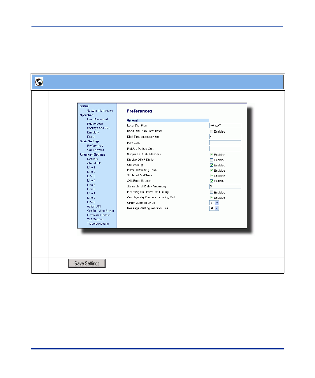
Aastra Web UI
1 Click on Basic Settings-> Preferences->General.
2The "Call Waiting" field is enabled by default. To disable this field, uncheck the box. This feature
allows you to enable or disable the call waiting feature on the IP phone.
3 Click to save your changes.
18 RN-001029-00, Rev 03, Release 2.1
Page 25

Mexico Tone Set Added to the IP Phones
You can configure ring tone sets on a global-basis on the IP phones. Ring tone sets
consist of tones customized for a specific country. A new ring tone set for Mexico
has been added in Release 2.1.
When you configure the country's tone set, the country-specific tone is heard on
the phone for the following:
- dial tone
- secondary dial tone
- ring tone
- busy tone
- congestion tones
- call waiting tone
- ring cadence pattern
A User and Administrator can configure ring tone sets using the Aastra Web UI
and the IP Phone UI. Additionally, an Administrator can configure ring tone sets
using the configuration files.
5i Series IP Phone Release Notes
Usability Features
See your IP Phone-specific User Guide or the IP Phone Administrator’s Guide for
information about configuring ring tone sets.
RN-001029-00, Rev 03, Release 2.1 19
Page 26

IP Phone Release Notes 2.1
Usability Features
Customizable Callers List and Services Keys
The IP phones currently have a Callers List key (all 5i Series phones) and a
Services key (55i, 57i, and 57i CT). In Release 2.1, two new parameters have been
added that allow you to specify URI overrides for these keys. These parameters
are:
• services script
• callers list script
Specifying URIs for these parameters cause the creation of an XML custom
application instead of the standard function of the Callers List and Services keys.
An Administrator can configure these parameters using the configuration files
only.
Creating Customizable Callers List and Services Keys
You use the following parameters to customize the Callers List and Services function.
Parameter –
services script
Description Allows you to specify a specific URI for accessing services after
Format Alphanumeric characters
Default Value N/A
Range N/A
Example services script: http://10.50.100.234/test.xml
Parameter –
callers list script
Description Allows you to specify a specific URI for accessing the Callers List after
Format Alphanumeric characters
Default Value N/A
Range N/A
Example callers list script: http://10.50.100.234/test.xml
Configuration Files aastra.cfg, <mac>.cfg
pressing the Services key. When this parameter is set, it overrides the
standard function of the Services key.
Configuration Files aastra.cfg, <mac>.cfg
pressing the Callers List key. When this parameter is set, it overrides
the standard function of the Callers List key.
20 RN-001029-00, Rev 03, Release 2.1
Page 27

5i Series IP Phone Release Notes
Configuration Parameters No Longer Case Sensitive
Previously, the configuration parameters an Administrator entered in the
configuration files were case sensitive and had to be entered exactly the way they
appeared in the IP Phone Administrator’s Guide (all lowercase).
In Release 2.1, the parameters are no longer case sensitive and can be entered in
either upper or lower case as desired.
Usability Features
RN-001029-00, Rev 03, Release 2.1 21
Page 28

IP Phone Release Notes 2.1
Deployability Features
Deployability Features
Server and Protocol Identification via DHCP Feature
The IP Phones now support additional download protocols according to RFC2131
and RFC1541 to support DHCP option 66.
Option 66 is part of the DHCP Offer message that the DHCP server generates to
tell the phone which configuration server it should use to download new firmware
and configuration files. In addition to supporting the IP address of a TFTP server
in this field, the phone now supports a URI format for specifying the other
configuration server types.
Your DHCP server configuration file, such as the dhcpd.conf file, may include one
of these lines to configure the configuration server protocol and the server details.
Protocol Format Examples
HTTP http://<server>/<path> option tftp-server-name “http://192.168.1.45”;
option tftp-server-name “http://192.168.1.45/path”;
option tftp-server-name “http://httpsvr.example.com/path”;
HTTPS https://<server>/<path> option tftp-server-name “https://192.168.1.45”;
option tftp-server-name “https://192.168.1.45/path”;
option tftp-server-name “https://httpssvr.example.com/
path”;
22 RN-001029-00, Rev 03, Release 2.1
Page 29

5i Series IP Phone Release Notes
Deployability Features
Protocol Format Examples
FTP ftp://user:password@ftpserver option tftp-server-name “ftp://192.168.1.45”;
option tftp-server-name “ftp://ftpsvr.example.com”;
(for anonymous user)
option tftp-server-name “ftp://userID:password@
ftpsvr.example.com”;
TFTP tftp://tftpserver option tftp-server-name “192.168.1.45”;
option tftp-server-name “tftpsvr.example.com”;
option tftp-server-name “tftp://tftpsvr.example.com”;
For more information about setting the download Protocol on the IP phones, see
the SIP IP Phone Administrator Guide.
RN-001029-00, Rev 03, Release 2.1 23
Page 30

IP Phone Release Notes 2.1
Security Features
Security Features
Transport Layer Security (TLS) Support
The phones now support a new transport protocol called Transport Layer
Security (TLS) and Persistent TLS. TLS is a protocol that ensures
communication privacy between the SIP phones and the Internet. TLS ensures
that no third party may eavesdrop or tamper with any message.
TLS is composed of two layers: the TLS Record Protocol and the TLS handshake
protocol. The TLS Record Protocol provides connection security with some
encryption method such as the Data Encryption Standard (DES). The TLS
Handshake Protocol allows the server and client to authenticate each other and to
negotiate an encryption algorithm and cryptographic keys before data is
exchanged. TLS requires the use of specific security certificate files to perform
TLS handshake:
• Root and Intermediate Certificates
• Local Certificate
•Private Key
• Trusted Certificate
When the phones use TLS to authenticate with the server, each individual call
must setup a new TLS connection. This can take more time when placing each
call. Thus, the IP phones also have a feature that allows you to setup the
connection to the server once and re-use that one connection for all calls from the
phone. It is called Persistent TLS. The setup connection for Persistent TLS is
established during the registration of the phone. If the phones are set to use
Persistent TLS, and a call is made from the phone, this call and all subsequent
calls use the same authenticated connection. This significantly reduces the delay
time when placing a call.
24 RN-001029-00, Rev 03, Release 2.1
Page 31

5i Series IP Phone Release Notes
Security Features
Notes:
1. Persistent TLS requires the outbound proxy server and outbound
proxy port parameters be configured in either the configuration files or
the Aastra Web UI (Advanced Settings->Global SIP->Basic SIP Network
Settings). There can be only one persistent TLS connection created per
phone. The phone establishes the TLS connection to the configured
outbound proxy.
2. If you configure the phone to use Persistent TLS, you must also
specify the Trusted Certificate file to use. The Root and Intermediate
Certificates, Local Certificate, and Private Key files are optional.
On the IP phones, an Administrator can configure TLS and Persistent TLS on a
global-basis only, using the configuration files or the Aastra Web UI.
RN-001029-00, Rev 03, Release 2.1 25
Page 32

IP Phone Release Notes 2.1
Security Features
Configuring TLS Using Configuration Files
You use the following parameters to configure TLS in the configuration files:
• sip transport protocol
• sips persistent tls
• sips root and intermediate certificates
• sips local certificate
• sips private key
• sips trusted certificates
Parameter –
sip transport protocol
Transport Protocol
(in Web UI)
Description The protocol that the Real-Time Transport Protocol (RTP) port on the IP
Format Integer
Default Value 1 - UDP
Range Valid values are:
Example sip transport protocol: 4
Aastra Web UI Advanced Settings->Global SIP->
Advanced SIP Settings
Configuration Files aastra.cfg, <mac>.cfg
phone uses to send out SIP signaling packets.
Notes:
1. If you set the value of this parameter to 4 (TLS), the phone checks
to see if the “sips persistent tls” is enabled. If it is enabled, the phone
uses Persistent TLS on the connection. If “sips persistent tls” is
disabled, then the phone uses TLS on the connection. If TLS is used,
you must specify the Root and Intermediate Certificates, the Local
Certificate, the Private Key, and the Trusted Certificates.
2. If the phone uses Persistent TLS, you MUST specify the Trusted
Certificates; the Root and Intermediate Certificates, the Local
Certificate, and the Private Key are optional.
0 - User Datagram Protocol (UDP) and
Transmission Control Protocol (TCP)
1 - UDP
2 - TCP
4- Transport Layer Security (TLS)
26 RN-001029-00, Rev 03, Release 2.1
Page 33

5i Series IP Phone Release Notes
Security Features
Parameter –
sips persistent tls
Description Enables or disables the use of Persistent Transport Layer Security (TLS).
Format Boolean
Default Value 0 (disabled)
Range 0 (disabled)
Example sips persistent tls: 1
Configuration Files aastra.cfg, <mac>.cfg
Persistent TLS sets up the connection to the server once and re-uses that
connection for all calls from the phone. The setup connection for
Persistent TLS is established during the registration of the phone. If the
phones are set to use Persistent TLS, and a call is made from the phone,
this call and all subsequent calls use the same authenticated connection.
This significantly reduces the delay time when placing a call.
Notes:
1. Persistent TLS requires the outbound proxy server and outbound
proxy port parameters be configured in either the configuration files or the
Aastra Web UI (Advanced Settings->Global SIP->Basic SIP Network
Settings). There can be only one persistent TLS connection created per
phone. The phone establishes the TLS connection to the configured
outbound proxy.
2. If you configure the phone to use Persistent TLS, you must also
specify the Trusted Certificate file to use. The Root and Intermediate
Certificates, Local Certificate, and Private Key files are optional.
1 (enabled)
RN-001029-00, Rev 03, Release 2.1 27
Page 34

IP Phone Release Notes 2.1
Security Features
Parameter –
sips root and intermediate
certificates
Root and Intermediate
Certificates
(in Web UI)
Description Allows you to specify the SIP Root and Intermediate Certificate files to use
Format <file name>.pem
Default Value N/A
Range N/A
Example sips root and intermediate certificates: cacert_openser.pem
Aastra Web UI Advanced Settings->TLS Support
Configuration Files aastra.cfg, <mac>.cfg
when the phone uses the TLS transport protocol to setup a call.
The Root and Intermediate Certificate files contain one root certificate and
zero or more intermediate certificates which must be placed in order of
certificate signing with root certificate being the first in the file. If the local
certificate is signed by some well known certificate authority, then that
authority provides the user with the Root and Intermediate Certificate files
(most likely just CA root certificate).
This parameter is required when configuring TLS (optional for Persistent
TLS.)
Note: The certificate files must use the format “.pem”. To create custom
certificate files to use on your IP phone, contact Aastra Technical Support.
28 RN-001029-00, Rev 03, Release 2.1
Page 35

5i Series IP Phone Release Notes
Security Features
Parameter –
sips local certificate
Local Certificate
(in Web UI)
Description Allows you to specify the Local Certificate file to use when the phone uses
Format <file name>.pem
Default Value N/A
Range N/A
Example sips local certificate: phonesLocalCert.pem
Parameter –
sips private key
Private Key
(in Web UI)
Description Allows you to specify a Private Key file to use when the phone uses the
Aastra Web UI Advanced Settings->TLS Support
Configuration Files aastra.cfg, <mac>.cfg
the TLS transport protocol to setup a call.
This parameter is required when configuring TLS (optional for Persistent
TLS.)
Note: The certificate file must use the format “.pem”. To create specific
certificate files to use on your IP phone, contact Aastra Technical Support.
Aastra Web UI Advanced Settings->TLS Support
Configuration Files aastra.cfg, <mac>.cfg
TLS transport protocol to setup a call.
This parameter is required when configuring TLS (optional for Persistent
TLS.)
Note: The key file must use the format “.pem”. To create specific private
key files to use on your IP phone, contact Aastra Technical Support.
Format <file name>.pem
Default Value N/A
Range N/A
Example sips private key: phone-privkey.pem
RN-001029-00, Rev 03, Release 2.1 29
Page 36

IP Phone Release Notes 2.1
Security Features
Parameter –
sips trusted certificates
Trusted Certificates
(in Web UI)
Description Allows you to specify the Trusted Certificate files to use when the phone
Format <file name>.pem
Default Value N/A
Range N/A
Example sips trusted certificates: trustedCert.pem
Aastra Web UI Advanced Settings->TLS Support
Configuration Files aastra.cfg, <mac>.cfg
uses the TLS transport protocol to setup a call.
The Trusted Certificate files define a list of trusted certificates. The phone’s
trusted list must contain the CA root certificates for all the servers it is
connecting to. For example, if the phone is connecting to server A which
has a certificate signed by CA1, and server B which has a certificate
signed by CA2, the phone must have CA1 root certificate and CA2 root
certificate in its Trusted Certificate file.
This parameter is required when configuring TLS or Persistent TLS.
Note: The certificate files must use the format “.pem”. To create custom
certificate files to use on your IP phone, contact Aastra Technical Support.
30 RN-001029-00, Rev 03, Release 2.1
Page 37

5i Series IP Phone Release Notes
Configuring TLS Using the Aastra Web UI
To configure TLS using the Aastra Web UI, you must enable TLS or Persistent
TLS first. Then you must define the TLS certificate file names that you want the
phone to use. Use the following procedure to configure TLS using the Aastra Web
UI.
Aastra Web UI
1 Click on Advanced Settings->Global SIP->Advanced SIP Settings.
Security Features
2 In the "Transport Protocol" field, select TLS or Persistent TLS.
Note: If configuring Persistent TLS, you must go to Advanced Settings->Global SIP->Basic Network
Settings and configure the “Outbound Proxy Server” and “Outbound Proxy Port” parameters.
3 Click to save your changes.
RN-001029-00, Rev 03, Release 2.1 31
Page 38

IP Phone Release Notes 2.1
Security Features
Aastra Web UI
4 Click on Advanced Settings->TLS Support.
32 RN-001029-00, Rev 03, Release 2.1
Page 39
5i Series IP Phone Release Notes
Security Features
Aastra Web UI
5 Enter the certificate file names and the private key file name in the appropriate fields.
The Root and Intermediate Certificate files contain one root certificate and zero or more intermediate
certificates which must be placed in order of certificate signing with root certificate being the first in
the file. If the local certificate is signed by some well known certificate authority, then that authority
provides the user with the Root and Intermediate Certificate files (most likely just CA root certificate).
The Trusted Certificate files define a list of trusted certificates. The phone’s trusted list must contain
the CA root certificates for all the servers it is connecting to. For example, if the phone is connecting
to server A which has a certificate signed by CA1, and server B which has a certificate signed by
CA2, the phone must have CA1 root certificate and CS2 root certificate in its Trusted Certificate file.
Notes:
1. If configuring TLS, you must specify the files for Root and Intermediate Certificates, the Local
Certificate, the Private Key, and the Trusted Certificates in order for the phone to receive calls.
2. If configuring Persistent TLS, you must specify the Trusted Certificates (which contains the trusted
certificate list). All other certificates and the Private Key are optional.
3. The certificate files and Private Key file names must use the format “.pem”.
4. To create custom certificate files and private key files to use on your IP phone, contact Aastra
Technical Support.
6 Click to save your changes.
RN-001029-00, Rev 03, Release 2.1 33
Page 40

IP Phone Release Notes 2.1
Security Features
Secure Real-Time Transfer Protocol (SRTP) Support with SDES Key Exchange
Release 2.1 includes support for Secure Real-time Transfer Protocol (SRTP),
using Session Description Protocol Security (SDES) key negotiation, for
encryption and authentication of RTP/RTCP messages sent and received by the
Aastra IP phones on your network.
As administrator, you specify the global SRTP setting for all lines on the IP
phone. You can choose among three levels of SRTP encryption, as follows:
• SRTP Disabled (default): IP phone generates and receives nonsecured RTP
calls. If the IP phone gets called from SRTP enabled phone, it ignores SRTP
tries to answer the call using RTP. If the receiving phone has SRTP only
enabled, the call fails; however, if it has SRTP preferred enabled, it will accept
RTP call.
• SRTP Preferred: IP phone generates RTP secured calls, and accepts both
secured and non-secured RTP calls. If the receiving phone is not SRTP
enabled, it sends non-secured RTP calls instead.
• SRTP Only: IP phone generates and accepts RTP secured calls only; all other
calls are rejected (fail).
An Administrator can override the global setting as necessary, configuring SRTP
support on a per-line basis. This allows IP phone users to have both secured and
unsecured lines operating on the same phone.
If an SRTP enabled IP phone initiates a call, and the receiving phone is also SRTP
enabled, the IP Phone UI displays a “lock” icon, indicating that the call is secure.
If the receiving phone does not support SRTP, the IP phone will send unsecured
RTP messages instead of SRTP encrypted messages. However in this case, the IP
Phone UI does not display the lock icon - indicating a non-secure call.
Note: If you enable SRTP, then you should also enable Transport Layer
Security (TLS). This prevents capture of the key used for SRTP
encryption. To enable TLC, set the Transport Protocol parameter
(located on the Global SIP Settings menu) to TLS.
An Administrator can configure SRTP on a global or per-line basis using the
configuration files and the Aastra Web UI.
34 RN-001029-00, Rev 03, Release 2.1
Page 41

5i Series IP Phone Release Notes
Security Features
Configuring SRTP Using Configuration Files
You use the following parameters to configure SRTP in the configuration files:
Global Parameter
• sip srtp mode
Per-Line Parameter
• sip lineN srtp mode
Global Parameter
Parameter –
sip srtp mode
Description This parameter determines if SRTP is enabled on this IP phone, as
Format Integer
Default Value 0 (disabled)
Range 0
Example sip srtp mode: 1
Aastra Web UI Advanced Settings->Global SIP->
RTP Settings
Configuration Files aastra.cfg, <mac>.cfg
follows:
• If set to 0, then disable SRTP.
• If set to 1 then SRTP calls are preferred.
• If set to 2, then SRTP calls only are generated/accepted.
1
2
RN-001029-00, Rev 03, Release 2.1 35
Page 42

IP Phone Release Notes 2.1
Security Features
Per-Line Parameter
Parameter –
sip lineN srtp mode
Description This parameter determines if SRTP is enabled on this line, as follows:
Format Integer
Default Value 0 (disabled)
Range -1
Example sip line1 mode: 1
Aastra Web UI Advanced Settings->Line <1-9>>
RTP Settings
Configuration Files aastra.cfg, <mac>.cfg
• If set to -1, then use the global setting for this line. (This is the
default setting.)
• If set to 0, then disable SRTP.
• If set to 1 then SRTP calls are preferred.
• If set to 2, then SRTP calls only are generated/accepted.
0
1
2
36 RN-001029-00, Rev 03, Release 2.1
Page 43

Configuring SRTP Using the Aastra Web UI
When you configure SRTP using the Aastra Web UI, you must first globally
configure SRTP support for the IP phone. Then, if you wish, you can configure
SRTP support on a per-line basis.
Use the following procedure to configure SRTP using the Aastra Web UI.
Aastra Web UI
Global Configuration
1 Click on Advanced Settings->Global SIP->RIP Settings.
5i Series IP Phone Release Notes
Security Features
2Set the “RTP Encryption” field to one of the following settings:
• SRTP Disabled: IP phone generates and receives nonsecured RTP calls.
• SRTP Preferred: IP phones generates RTP secured calls, and accepts both secured and
non-secured RTP calls.
• SRTP Only: IP phones generates and accepts RTP secured calls only; all other calls are
rejected.
RN-001029-00, Rev 03, Release 2.1 37
Page 44

IP Phone Release Notes 2.1
Security Features
Aastra Web UI
3 Click to save your changes.
Per-Line Configuration
1 Note: Setting a per-line SRTP configuration overrides the global SRTP configuration setting.
Click on Advanced Settings->Line <1-9>->RTP Settings.
2Set the “RTP Encryption” field to one of the following settings:
• SRTP Disabled: IP phone generates and receives nonsecured RTP calls on this line.
• SRTP Preferred: IP phones generates RTP secured calls, and accepts both secured and
non-secured RTP calls on this line.
• SRTP Only: IP phones generates and accepts RTP secured calls only on this line; all other calls
are rejected.
3 Click to save your changes.
38 RN-001029-00, Rev 03, Release 2.1
Page 45

5i Series IP Phone Release Notes
XML Features
New “doneAction” Attribute for XML Text Screen Object
You us e t h e AastraIPPhoneTextScreen object to display text to the LCD screen
on the IP Phone. The screen text wraps appropriately and can scroll to display a
message longer then four lines.
After implementing this object, text displays to the LCD on the IP phone.
A user can scroll through the screens as required. If you use the
“destroyOnExit” attribute in the XML script, when the user exits the
XML screens, the screens are destroyed.
A new feature in Release 2.1 allows specific text screens to redisplay for
redirection to a new page by using the “doneAction” attribute and
specifying the new page to go to in the XML script.
XML Features
Notes:
1. You can use the “destroyOnExit” attribute with any XML object as
required.
2. You can use the “doneAction” attribute with the
AastraIPPhoneTextScreen and AastraIPPhoneFormattedTextScreen
objects only.
3. For all available parameters you can use for the Text Screen object, and
for an explanation of each parameter, see Aastra Telecom’s
"XML Developer’s Guide".
Implementation
The following is how you would implement the Text Screen object.
Softkey
•6=Done
RN-001029-00, Rev 03, Release 2.1 39
:
Page 46

IP Phone Release Notes 2.1
XML Features
XML Description:
<AastraIPPhoneTextScreen doneAction=”HTTP address”>
<Title>Screen Title</Title>
<Text> The screen text goes here</Text>
</AastraIPPhoneTextScreen>
XML Example:
<AastraIPPhoneTextScreen doneAction=”http://10.50.10.117/
test.xml”>
<Title>Screen Object</Title>
<Text>For more information about this test, press Done.</Text>
</AastraIPPhoneTextScreen>
Note: This example displays text that you can scroll through on the LCD
screen. As you scroll the screen, and then press DONE (55i, 57i, 57i CT)
or the RIGHT ARROW key (53i), the screen redirects you to the
location specified in the script. After pressing DONE or the RIGHT
ARROW key, the phone checks if a “doneAction” exists in the XML
script. If it does, the screen gets redirected to the location specified. If it
does not exist, then the scrolled screens use the “destroyOnExit”
attribute and destroy the screens.
XML Screen Example:
6FUHHQ2EMHFW
)RUPRUHLQIRUPDWLRQDERXW
WKLVWHVWSUHVV'21(
'RQH
7(67
7KLVVFUHHQGLVSOD\VWKH+77
VFUHHQWKDW\RXKDYHEHHQ
UHGLUHFWHGWR
'RQH
40 RN-001029-00, Rev 03, Release 2.1
Page 47

XML Support for Answer and Ignore Softkeys
In Release 2.1, when the IP phone receives an XML application (either via a post
or an incoming action URI) while a call is coming into the phone, the user can
either answer or ignore the call with new softkeys that display (55i, 57i, and 57i
CT), or press the left and right arrow keys (53i), without canceling the XML
application.
For a 55i, 57i, and 57i CT, an Administrator can use the “Answer” and “Ignore”
attributes in an XML script to implement this feature. For a 53i, an Administrator
can use the “allowAnswer” attribute with the AastraIPPhoneTextScreen XML
object. Valid values for the “allowAnswer” attribute are “yes” or “no” (default).
For 55i, 57i, and 57i CT:
•The Answer and Ignore softkeys display on the LCD when the phone has an
incoming call at the same time it receives an XML application.
• XML applications are destroyed if the phone receives a call after the XML
has been rendered.
5i Series IP Phone Release Notes
XML Features
When the Answer softkey displays, you can press it to answer the incoming call
without disturbing the current XML application. When you answer the call, the
softkey disappears from the LCD. Pressing the Ignore softkey ignores the
incoming call without disturbing the current XML application.
Implementation (55i, 57i, 57i CT)
Softkeys
:
•1=Answer
• 2=Ignore
RN-001029-00, Rev 03, Release 2.1 41
Page 48

IP Phone Release Notes 2.1
XML Features
XML Example:
<SoftKey index="1">
<Label>Answer</Label>
<URI>SoftKey:Answer</URI>
</SoftKey>
<SoftKey index="2">
<Label>Answer</Label>
<URI>SoftKey:Ignore</URI>
</SoftKey>
XML Screen Example:
,
!N8-,APPLICATIONCAN
DISPLAYHEREWHILEACALL
ISCOMINGIN
!NSWER
)GNORE
*OHN3MITH
For 53i:
•An <Ignore Answer> line displays on the LCD when the phone receives an
incoming call at the same time it receives an XML application.
• XML applications are destroyed if the phone receives a call after the XML
has been rendered.
When the <Ignore Answer> line displays, you can press the Right Arrow key
(Answer) to answer the incoming call without disturbing the current XML
application. When you answer the call, the <Ignore Answer> line disappears from
the LCD. Pressing the Left Arrow key ignores the incoming call without
disturbing the current XML application.
42 RN-001029-00, Rev 03, Release 2.1
Page 49

Implementation (53i)
5i Series IP Phone Release Notes
XML Features
XML Example
<AastraIPPhoneTextScreen allowAnswer = "yes">
<Title>Screen Object</Title>
<Text>The screen object can be implemented similar to the
firmware info screen. Note that white space is preserved in XML so
the display should word-wrap appropriately. Only three lines can
display at a time.</Text>
</AastraIPPhoneTextScreen>
:
XML Screen Example:
!N8-,APPLICATIONCANDISPLAY
HEREWHILEACALLISCOMINGIN
,JQRUH $QVZHU
RN-001029-00, Rev 03, Release 2.1 43
Page 50

IP Phone Release Notes 2.1
XML Features
XML Softkey for Special Characters (55i, 57i, and 57i CT only)
In Release 2.1, the IP Phone can dynamically receive a Symbol List when it
receives the AastraIPPhoneInputScreen XML object. You can have a single
symbol specified for the softkey, or you can have a list of symbols. When there is
only one symbol in the list, the symbol displays with no delay. When there is a list
of symbols, you can keep pressing the symbol softkey to cycle through the list of
symbols to select the one you want to use.
To display a list of customized symbols to the phone’s softkey, the server must
include the list of characters in the URI field of the XML softkey script. The URI
must be in the format:
SymbolList=”<Symbol List content>”
The content of the Symbol List must be encapsulated by quotes. You can specify
multiple symbols in one URI. For example, the SymbolList="@#” specifies the
@ and # symbols
Note: You can have multiple Symbol List softkeys with different lists of
symbols. The maximum length of the data in a Symbol List is 230
characters.
.
There are some special characters that needed to be encoded due to XML
limitations. The following table specifies these characters.
Symbol XML Encoding
single quote (‘) '
double quote (“) "
greater-than sign (>) >
less-than sign (<) <
ampersand (&) &
The following is an example XML URI using the characters in the table above:
SymbolList="@#&><"
The Symbol List content for this URI is @, #, &, >, <.
44 RN-001029-00, Rev 03, Release 2.1
Page 51

Implementation
5i Series IP Phone Release Notes
XML Features
Softkeys
:
• 1 = <Single Symbol or Symbol List>
XML Softkey Example
<SoftKey index="1">
<Label>Symbols</Label>
<URI>SoftKey:SymbolList="@#=&"</URI>
</SoftKey>
:
XML Object and Softkey Example:
<AastraIPPhoneInputScreen type = "IP">
<Title>Email</Title>
<SoftKey index="1">
<Label>Symbols</Label>
<URI>SoftKey:SymbolList="@"</URI>
</SoftKey>
<SoftKey index = "2">
<Label> Backspace </Label>
<URI>SoftKey:Exit</URI>
</Softkey>
<SoftKey index = "3">
<Label> Dot </Label>
<URI>SoftKey:Exit</URI>
</Softkey>
<Prompt>Email Address:</Prompt>
<URL>http://myserver.com/myscript.com</URL>
<Parameter>email</Parameter>
<Default></Default>
<AastraIPPhoneInputScreen>
XML Screen Example:
%MAIL
%MAIL!DDRESS
3YMBOLS
"ACKSPACE
$OThv
RN-001029-00, Rev 03, Release 2.1 45
Page 52

IP Phone Release Notes 2.1
Sylantro Interoperability Features
Sylantro Interoperability Features
Multi-Stage Digit Collection (Billing Codes) Support for Sylantro Servers
This release of the Aastra IP Phones supports Multi-Stage Digit Collection
(billing codes) for Sylantro Servers. Sylantro Server features, like mandatory and
optional billing codes, requires that the application server notify the phone to
collect more digits before completing the call. The IP phone is able to collect
digits in two stages to support the billing code feature.
Aastra IP Phone users are prompted to enter the correct billing code when they
dial these numbers:
• External numbers.
• Eternal numbers dialed using a Speeddial key.
Billing Codes Implementation Notes
Note the following implementation information:
• IP phone users may enter a 2-9 digit billing code. Billing codes may not start
with either 0 (Operator) or 9 (external calls).
• When using Sylantro Click-to-Call, IP phone users select a billing code from
a pull-down menu.
• When placing a call, a secondary dial tone alerts IP phone users to enter the
billing code. The IP phone UI also displays a “Enter Billing Code” message.
• If an IP phone user redials a number, they do not have to re-enter the billing
code. The billing code information is maintained and processed accordingly.
• If an IP phone user enters an invalid billing code, the call fails.
46 RN-001029-00, Rev 03, Release 2.1
Page 53

5i Series IP Phone Release Notes
Sylantro Interoperability Features
Mandatory versus Optional Billing Codes
This release of the Aastra IP phones supports two types of billing codes:
Mandatory and Optional. The Sylantro server configuration determines which
type of billing code is used on the IP phones.
• Mandatory billing codes: Calls are not connected until the user enters a valid
billing code. The user dials the phone number. When prompted for billing
codes, user dials the billing code.
For example, suppose the IP phone user is using billing code 300, and dialing
the external number 617-238-5500. The IP user then enters the number using
the following format:
6172385000#300
Using mandatory billing codes, if the user is configuring a Speeddial number,
then they enter the number using the following format:
<phonenumber>%23<billingcode>
To use this format with the default dial plan terminator (#), the # sign required
by Sylantro as a delimiter should be represented as an escaped character by
using the sequence %23. The speed dial format for an external number that
includes a mandatory billing code becomes:
<phonenumber>%23<billing code>
• Optional billing codes: The user dials an optional billing code by dialing
*50, followed by the billing code digits. When prompted for additional digits,
user enters the phone number.
For example, suppose the IP phone user is using billing code 500, and dialing
the external number 617-238-5000. The IP user then enters the number using
the following format:
*50500#6172385000
If the user is dialing configuring a Speeddial number, then they enter the
number using the following format:
*50<billingcode>#<phonenumber>
RN-001029-00, Rev 03, Release 2.1 47
Page 54

IP Phone Release Notes 2.1
Sylantro Interoperability Features
To use this format with the default dial plan terminator (#), the # sign
required by Sylantro as a delimiter should be represented as an escaped
character by using the sequence %23. The speed dial format for an
external number that includes an optional billing code becomes:
*50<billing code>%23<phone number>
Numbers Not Requiring Billing Codes
Billing codes are not required for the following two types of calls:
• Emergency calls (E911)
• Calls between extensions
48 RN-001029-00, Rev 03, Release 2.1
Page 55

5i Series IP Phone Release Notes
Sylantro Interoperability Features
Directed Call Pickup/Group Call Pickup Support for Sylantro Servers
Aastra IP phones now support the Sylantro Directed Call Pickup (DCP) and
Group Call Pickup (GCP) features.
The Directed Call Pickup/Group Call Pickup feature allows you to intercept - or
pickup - a call on a monitored extension. An Administrator or User can configure
this feature using the Aastra Web UI to create a DCP or GCP softkey on the IP
phone. When you configure a DCP softkey, you specify the extension that you
want to monitor. Then, when the monitored extension receives a call, you press
the DCP softkey to “pickup” (intercept) it. If the monitored extension receives
multiple incoming calls simultaneously, the IP Phone UI displays a list of
incoming calls. You select a call from this list, and are connected to the call.
When you configure a GCP softkey, you specify the ring group that you want to
monitor for incoming calls. For example, suppose an Operator configures a GCP
softkey to monitor incoming calls for a specific ring group (extensions
2200-2210). When an incoming call is received on any of these extensions, the
Operator presses the GCP softkey and is connected to the call. If multiple
incoming calls are received simultaneously, the Operator does the following
actions:
• Presses the GCP softkey. The Operator Phone UI displays the current list of
incoming calls (see below).
• Selects an extension to “pickup” first.
• Presses the Pickup softkey. The Operator is connected to the incoming call.
Select an extension
Press the Pickup
softkey to intercept
the call
RN-001029-00, Rev 03, Release 2.1 49
DCP on line:
1. 2201
2. 2204
3. 2210
Pickup
Cancel
Page 56

IP Phone Release Notes 2.1
Sylantro Interoperability Features
Configuring DCP/GCP Using Configuration Files
You use the following parameter to configure DCP and GCP in the configuration
files:
• dcp
Parameter –
dcp
Directed Call Pickup
(in Web UI)
Description Configures a new softkey that functions as a Directed Call Pickup
Format Te xt
Default Value N/A
Range N/A
Examples Directed Call Pickup on Extension 2200
Aastra Web UI Operation->Softkeys and XML->Type
Operation->Programmable Keys->Type
Operation->Expansion Module N->Type
Configuration Files aastra.cfg, <mac>.cfg
(DCP) or Group Call Pickup (GCP) key.
softkey2 type: dcp
softkey2 label: dcp2200
softkey2 value: 2200
softkey2 states: incoming outgoing idle connected
Group Call Pickup on group_A
softkey3 type: dcp
softkey3 label: gcp_A
softkey3 value: groupcallpickup
softkey3 states: incoming outgoing idle connected
50 RN-001029-00, Rev 03, Release 2.1
Page 57

Configuring Directed Call Pickup (DCP) Using the Aastra Web UI
Use the following procedure to configure Directed Call Pickup using the Aastra
Web UI .
Aastra Web UI
1 Click on Operation->Softkeys and XML.
5i Series IP Phone Release Notes
Sylantro Interoperability Features
2 Select a key for which to configure Directed Call Pickup.
3 In the “Type ” field, select Directed Call Pickup.
4 In the “Label” field, specify a name for this Directed Call Pickup softkey.
For example: DCP2200
5 In the “Value” field, specify the extension you want to intercept when you press this softkey.
For example: 2200
6 Click to save your changes.
RN-001029-00, Rev 03, Release 2.1 51
Page 58

IP Phone Release Notes 2.1
Sylantro Interoperability Features
Configuring Group Call Pickup (GCP) Using the Aastra Web UI
Use the following procedure to configure Group Call Pickup using the Aastra
Web UI .
Note: A ring group must be configured on the Sylantro Server in order
for a GCP softkey to function.
Aastra Web UI
1 Click on Operation->Softkeys and XML.
2 Select a key for which to configure Group Call Pickup.
3 In the “Type ” field, select Directed Call Pickup.
4 In the “Label” field, specify a name for this Directed Call Pickup softkey.
For example: GCP_A
5 In the “Value” field, enter groupcallpickup.
6 Click to save your changes.
52 RN-001029-00, Rev 03, Release 2.1
Page 59

Autodial (Hotline and Warmline) Feature
This release of the Aastra IP phones includes an “Autodial” feature. When you
configure Autodial on an IP phone, the phone automatically dials a preconfigured
number whenever it is off-hook. Depending on the configuration you specify, the
Autodial functions as either a “hotline”, or as a “warmline,” as follows:
• Hotline: The IP phone immediately dials a preconfigured number when you
lift the handset.
• Warmline: The IP phone waits for a specified amount of time after you lift the
handset before dialing a preconfigured number. If you do not dial a number
within the time allotted, then the IP phone begins to dial the number.
By default, the Autodial feature functions as a hotline. If you want Autodial to
function as a warmline, you can use the Autodial “time-out” parameter to specify
the length of time (in seconds) the IP phone waits before dialing a preconfigured
number.
As administrator, you configure Autodial globally, or on a per-line basis, for an IP
phone. The line setting overrides the global setting. For example, you can disable
Autodial on a specific line simply by setting the line’s autodial number parameter
to empty (blank).
5i Series IP Phone Release Notes
Sylantro Interoperability Features
Note: Please read the following important information before
configuring Autodial on your IP phone:
• Any speeddial numbers that you configure on an IP phone are not
affected by autodial settings.
• If you configure autodial on your IP phone, any lines that function as
hotlines do not accept conference calls, transferred calls, and/or
intercom calls.
RN-001029-00, Rev 03, Release 2.1 53
Page 60

IP Phone Release Notes 2.1
Sylantro Interoperability Features
Configuring AutoDial Support Using Configuration Files
You use the following parameters to configure Autodial support in the
configuration files:
Global Configuration
• sip autodial number
• sip autodial timeout
Per-Line Configuration
• sip lineN autodial number
• sip lineN autodial timeout
AutoDial Global Configuration
Parameter –
sip autodial number
Autodial Number
(in Web UI)
Description Globally specifies the SIP phone number that the IP phone autodials
Format Integer
Default Value Blank
Range Any valid SIP number
Examples sip autodial number: 8500
Aastra Web UI Advanced Settings>Global SIP>
Autodial Settings
Configuration Files aastra.cfg, <mac>.cfg
when the handset is lifted from the phone cradle. An empty (blank)
value disables autodial on the phone.
54 RN-001029-00, Rev 03, Release 2.1
Page 61

5i Series IP Phone Release Notes
Sylantro Interoperability Features
Parameter –
sip autodial timeout
Autodial Timeout
(in Web UI)
Description Globally specifies the time, in seconds, that the phone waits to dial a
Format Integer
Default Value 0
Range 0 to 120
Examples sip autodial timeout: 30
Aastra Web UI Advanced Settings>Global SIP>
Autodial Settings
Configuration Files aastra.cfg, <mac>.cfg
preconfigured number after the handset is lifted from the IP phone
cradle.
If this parameter is set to 0 (hotline), the phone immediately dials a
preconfigured number when you lift the handset. If this parameter is set
to a value greater than 0, the phone waits the specified number of
seconds before dialing the preconfigured number (warmline) when you
lift the handset.
Default is 0 (hotline).
AutoDial Per-Line Configuration
Parameter –
sip lineN autodial number
Aastra Web UI Advanced Settings>LineN>Autodial Settings
Configuration Files aastra.cfg, <mac>.cfg
Autodial Number
(in Web UI)
Description On a per-line basis, this parameter specifies the SIP phone number that
the IP phone autodials when the handset is lifted from the phone cradle.
Valid values can be:
-1 (Default) The phone uses the global
autodial setting for this line.
Blank (Empty field) Disables autodial on this line.
Valid SIP Number Dials the SIP number specified for this line.
Format Integer
Default Value -1
Range Any valid SIP number.
Examples sip line1 autodial number: 8500
RN-001029-00, Rev 03, Release 2.1 55
Page 62

IP Phone Release Notes 2.1
Sylantro Interoperability Features
Parameter –
sip lineN autodial timeout
AutoDial Timeout
(in Web UI)
Description On a per-line basis, this parameter specifies the time, in seconds, that
Format Integer
Default Value 0
Range 0 to 120
Examples sip line1 autodial timeout: 30
Aastra Web UI Advanced Settings>LineN>Autodial Settings
Configuration Files aastra.cfg, <mac>.cfg
the phone waits to dial a preconfigured number after the handset is
lifted from the IP phone cradle.
If this parameter is set to 0 (hotline), the phone immediately dials a
preconfigured number when you lift the handset. If this parameter is set
to a value greater than 0, the phone waits the specified number of
seconds before dialing the preconfigured number (warmline) when you
lift the handset.
Default is 0 (hotline).
56 RN-001029-00, Rev 03, Release 2.1
Page 63

Sylantro Interoperability Features
Configuring Autodial Using the Aastra Web UI
Use the following procedure to configure the Autodial feature on an IP phone
using the Aastra Web UI.
By default, your IP phone uses the global settings you specify for Autodial for all
lines on your IP phone. However, you can also configure Autodial on a per-line
basis.
Aastra Web UI
Global Configuration
1 Click on Advanced Settings->Global SIP->Autodial Settings.
5i Series IP Phone Release Notes
2 In the “Autodial Number” field, specify the SIP number that the IP phone dials whenever the IP
phone is off-hook.
For example: 8500
RN-001029-00, Rev 03, Release 2.1 57
Page 64

IP Phone Release Notes 2.1
Sylantro Interoperability Features
Aastra Web UI
3 In the “Autodial Timeout” field, specify a value for the timer as follows:
• If you want the IP phone to autodial the number immediately (hotline) whenever the IP phone is
off-hook, accept the default value of 0.
• If you want to specify a length of time for the IP phone to wait before dialing the number, enter
the length of time (in seconds). For example: 30
4 Click to save your changes.
Per-Line Configuration
1 Click on Advanced Settings->Line <1 - 9>->Autodial Settings.
2 Do one of the following actions:
• To allow this line to use the global autodial settings, click on the Use Global Settings parameter
to enable it, then click to save your changes.
• To specify a different autodial configuration for this specific line, disable the Use Global
Settings parameter. Then proceed to step 3.
58 RN-001029-00, Rev 03, Release 2.1
Page 65

5i Series IP Phone Release Notes
Sylantro Interoperability Features
Aastra Web UI
3 In the “Autodial Number” field, specify the SIP number for this line that the IP phone dials
whenever the IP phone is off-hook as follows:
• If set to -1, then the global autodial settings for this IP phone to this line.
• If set to empty (blank), then disable Autodial on this line.
• If set to a valid SIP number, dial the SIP number specified for this line. For example: 8500
4 In the “Autodial Timeout” field, specify a value for the timer for this line as follows:
• If you want the IP phone to autodial the number immediately (hotline) whenever the IP phone is
off-hook, accept the default value of 0.
• If you want to specify a length of time for the IP phone to wait before dialing the number, enter
the length of time (in seconds). For example: 30
5 Click to save your changes.
RN-001029-00, Rev 03, Release 2.1 59
Page 66

IP Phone Release Notes 2.1
Sylantro Interoperability Features
Centralized Conferencing for Sylantro Servers
Release 2.1 of the Aastra IP phones includes support for centralized conferencing
(Ad-Hoc conferencing) for Sylantro and Broadsoft servers. This feature provides
centralized conferencing on the SIP server (versus localized, on the phone) and
allows IP phone users to do these tasks:
• Conference two active calls together into a conference call.
• When on an active conference call, invite another party into the call.
• Create simultaneous conference calls on the same IP phone (Sylantro servers
only). For example, the IP phone user at extension 2005 could create these
two conferences, and put one conference on hold while conversing with the
other party:
— Line 1: conference together extensions 2005, 2010, and 2020.
— Line 2: conference together extensions 2005, 2011 and 2021.
When an IP phone user is connected to multiple conference calls, some
outbound proxies have maximum call “hold” time set from 30-90 seconds.
After this time, the call that is on hold is disconnected.
• Disconnect from an active conference call while allowing the other callers to
remain connected.
• Ability to create N-way conference.
• Join two active calls together into a conference call.
• Incoming or outgoing active call can join any of the existing conferences.
If the administrator does not configure centralized conferencing, then the IP
phone uses localized conferencing by default.
Note: When you configure centralized conferencing globally for an IP
Phone, the global settings apply to all lines. Although, for the global
setting to work on soft lines, the user must configure the lines with the
applicable phone number.
An Administrator can configure centralized conferencing on a global or per-line
basis using the configuration files or the Aastra Web UI.
To use centralized conferences, see your Phone-specific User Guide.
60 RN-001029-00, Rev 03, Release 2.1
Page 67

5i Series IP Phone Release Notes
Sylantro Interoperability Features
Configuring Centralized Conferencing Using the Configuration Files
You use the following parameter to configure centralized conferencing in the
configuration files:
Global Parameter
• sip centralized conf
Per-Line Parameter
• sip lineN centralized conf
Parameter –
sip centralized conf
Conference Server URI
(in Web UI)
Description Globally enables or disables SIP centralized conferencing for an IP
Aastra Web UI Advanced->Global SIP Settings->
Basic SIP Network Settings
Configuration Files aastra.cfg, <mac>.cfg
phone as follows:
• To disable centralized conferencing, leave this field empty (blank).
• To enable SIP centralized conferencing, then do one of the following
actions:
— If you have specified a proxy server/registrar server, then to
reach the media server via the proxy server, set this field to
one of the following:
conf (Sylantro server), or
Conference (Broadsoft server)
By setting this field to conf, you specify conf@<proxy_server
_address>: <proxy_port>. For example, if the proxy server address
is 206.229.26.60 and the proxy port used is 10060, then by setting
this parameter to conf, you are specifying the following:
conf@206.229.26.60:10060
— To reach the media server using a different address/port than
that specified by the proxy, set this field to the following:
conf@<media_server _address>: <media_port>
Format String
Default Value Blank
Example sip centralized conf: conf
RN-001029-00, Rev 03, Release 2.1 61
Page 68

IP Phone Release Notes 2.1
Sylantro Interoperability Features
Parameter –
sip lineN centralized conf
Conference Server URI
(in Web UI)
Description Enable or disable per-line SIP centralized conferencing for an IP phone
Aastra Web UI Advanced->Line <1 thru 9>->
Basic SIP Network Settings
Configuration Files aastra.cfg, <mac>.cfg
as follows:
• To disable centralized conferencing, leave this field empty (blank).
• To enable SIP centralized conferencing on a specific line, do one of
the following actions:
— If you have specified a proxy server/registrar server, then to
reach the media server via the proxy server, set this field to
one of the following:
conf (Sylantro server), or
Conference (Broadsoft server)
By setting this field to
_address>: <proxy_port>. For example, if the proxy server address
is 206.229.26.60 and the proxy port used is 10060, then by setting
this parameter to conf, you are specifying the following:
conf@206.229.26.60:10060.
conf, you specify conf@<proxy_server
— To reach the media server using a different address/port than
that specified by the proxy, set this field to the following:
conf@<media_server _address>: <media_port>
Format String
Default Value Blank
Examples sip line3 centralized conf: conf
62 RN-001029-00, Rev 03, Release 2.1
Page 69

5i Series IP Phone Release Notes
Sylantro Interoperability Features
Configuring Centralized Conferencing Using the Aastra Web UI
Use the following procedure to configure centralized conferencing on an IP
phone.
Aastra Web UI
Global Configuration
1 Click on Advanced Settings->Global SIP Settings->Basic SIP Network Settings.
2 In the “Conference Server URI” field, do one of the following actions:
• To disable centralized conferencing on the IP phone, leave this field empty (blank).
• To enable SIP centralized conferencing on the IP phone, do one of the following actions:
— If you have specified a proxy server/registrar server, then to reach the media server via the
proxy server, set this field to one of the following:
conf (Sylantro server), or
Conference (Broadsoft server)
By setting this field to conf or Conference, you specify conf@<proxy_server _address>:
<proxy_port>. For example, if the proxy server address is 206.229.26.60 and the port used
is 10060, then by setting this parameter to conf, you are specifying the following:
conf@206.229.26.60:10060.
— To reach the media server using a different address/port than that specified by the proxy,
set this field to the following:
conf@<media_server _address>: <media_port>
RN-001029-00, Rev 03, Release 2.1 63
Page 70

IP Phone Release Notes 2.1
Sylantro Interoperability Features
Aastra Web UI
3 Click to save your changes.
Per-Line Configuration
1 Click on Advanced Settings->Line <#>->Basic SIP Network Settings
2 In the “Conference Server URI” field, do one of the following actions:
• To disable centralized conferencing on this line, leave this field empty (blank).
• To enable SIP centralized conferencing on this line, do one of the following actions:
— If you have specified a proxy server/registrar server, then to reach the media server via the
proxy server, set this field to one of the following:
conf (Sylantro server), or
Conference (Broadsoft server)
By setting this field to conf or Conference, you specify conf@<proxy_server _address>:
<proxy_port>.
— To reach the media server using a different address/port than that specified by the proxy,
set this field to the following:
conf@<media_server _address>: <media_port>
3 Click to save your changes.
64 RN-001029-00, Rev 03, Release 2.1
Page 71

5i Series IP Phone Release Notes
Sylantro Interoperability Features
Automatic Call Distribution (ACD) Support for Sylantro Servers
Release 2.1 of the IP phones includes Automatic Call Distribution (ACD) support
for Sylantro servers. The ACD feature allows the Sylantro server to distribute
calls from a queue to registered IP phone users (agents).
To use the ACD feature on an IP phone, the administrator first must configure an
an ACD softkey or programmable key. When an IP phone user wants to subscribe
to a queue (in order to receive incoming calls), the user presses the ACD key. The
IP phone UI prompts the user to specify the following information:
• User ID: the phone number(s) used to login into the queue.
• Password: the password used to login to the queue.
• Available/unavailable: Shows the current status of the IP phone. Specifies if
the IP phone user is available/unavailable to receive a call from the queue.
This parameter is set to “unavailable” by default.
When the IP phone user is ready to receive calls from the server, the user logs into
a queue. Depending on the server configuration, the IP phone is either in an
“unavailable” or “available” state. If the phone is set to “available” then the server
begins to distribute calls to this phone immediately. If the phone is set to
unavailable, then server waits until the IP phone user manually changes the phone
status to “available” (using the IP phone UI) before distributing calls.
Whenever the IP phone user answers a call, or misses a call, the server
automatically changes the phone’s status to unavailable. The server updates it
database with this new information and no longer distributes calls to this phone.
The IP phone will remain in this state until:
— the IP phone user makes himself “available” again.
— the ACD auto-availability timer expires. This occurs only if the
administrator has configured an ACD auto-availability timer as described
on page 66).
The IP phone user can also choose to manually change the phone status to
unavailable, using the IP Phone UI.
Note: Aastra recommends configuring no more than a single ACD softkey or programmable key
per IP phone.
RN-001029-00, Rev 03, Release 2.1 65
Page 72

IP Phone Release Notes 2.1
Sylantro Interoperability Features
ACD LED Table
The LED located next to the ACD softkey flashes or remains solid to indicate the
current status of the IP phone. In addition, an icon on the IP Phone UI reminds IP
phone users of their current status.
The following table describes the meaning of the ACD LEDs and icons for each
model IP phone.
Phone Model
53i Solid Red LED Blinking red LED No LED
55i, 57i, 57i CT Solid Red LED
Status: Logged In
and Available
icon
Status: Unavailable Logged Out
Blinking Red LED
Blinking icon
No LED
icon
Using the ACD Auto-Available Timer
Whenever the IP phone user answers a call, or misses a call, the server
automatically changes the phone’s status to unavailable. The administrator can
control how long the IP phone remains in the unavailable state by configuring an
auto-available timer. When the timer expires, the IP phone status is automatically
changed to available. The default setting for the timer is 60 seconds.
66 RN-001029-00, Rev 03, Release 2.1
Page 73

5i Series IP Phone Release Notes
Sylantro Interoperability Features
Configuring ACD Softkeys Using Configuration Files (55i, 57i, 57i CT)
You use the following parameters to configure ACD support in the configuration
files for 55i, 57i, 57i CT:
• softkeyN type
• softkeyN label
• softkeyN line
• softkeyN states
A sample configuration file is shown below:
softkey1 type: acd
softkey1 label: sales
softkey1 line: 1
softkey1 states: idle
In addition to the above parameters, you can also use the following parameters to
configure ACD support in the configuration files for 57i, 57i CT:
• topsoftkeyN type
• topsoftkeyN label
• topsoftkeyN line
• topsoftkeyN states
A sample configuration file is shown below:
topsoftkey1 type: acd
topsoftkey1 label: sales
topsoftkey1 line: 1
topsoftkey1 states: idle
For complete parameter descriptions, refer to the following tables.
RN-001029-00, Rev 03, Release 2.1 67
Page 74

IP Phone Release Notes 2.1
Sylantro Interoperability Features
Parameters –
softkeyN type
Auto Call Distribution
(in Web UI)
Description Defines the type of softkey that is configured for this key.
Format Te xt
Default Value none
Default Range See the IP Phone Administrator’s Guide.
Example softkey1 type: acd
Parameters –
softkeyN label
Auto Call Distribution
(in Web UI)
Description Text label that displays on the IP phone for this softkey. Typically an
Format Te xt
Default Value Blank
Range See the IP Phone Administrator’s Guide.
Example softkey1 label: Sales
Aastra Web UI Operation->Softkeys and XML
Configuration Files aastra.cfg, <mac>.cfg
To configure an ACD softkey, set this parameter to “acd”
Aastra Web UI Operation->Softkeys and XML
Configuration Files aastra.cfg, <mac>.cfg
easily recognizable name identifying the queue to which this softkey
subscribes. For example: Sales
68 RN-001029-00, Rev 03, Release 2.1
Page 75

5i Series IP Phone Release Notes
Sylantro Interoperability Features
Parameters –
softkeyN line
Auto Call Distribution
(in Web UI)
Description This is the line associated with the softkey you are configuring.
Format Integer
Default Value 1
Range 1 through 9
Example softkey1 line: 1
Parameters –
softkeyN states
Auto Call Distribution
(in Web UI)
Description Displays the status of the phone when a softkey is pressed. To
Format Te xt
Default Value For softkey type - ACD:
Range See IP Phone Administrator’s Guide.
Example softkey1 states: idle
Aastra Web UI Operation->Softkeys and XML
Configuration Files aastra.cfg, <mac>.cfg
For example: 1
Aastra Web UI Operation->Softkeys and XML
Configuration Files aastra.cfg, <mac>.cfg
configure an ACD softkey, set the state to “idle.”
idle
RN-001029-00, Rev 03, Release 2.1 69
Page 76

IP Phone Release Notes 2.1
Sylantro Interoperability Features
Parameters –
topsoftkeyN type
Auto Call Distribution
(in Web UI)
Description Defines the type of top softkey that is configured for this key.
Format Te xt
Default Value none
Default Range See the IP Phone Administrator’s Guide.
Example topsoftkey1 type: acd
Parameters –
topsoftkeyN label
Auto Call Distribution
(in Web UI)
Description Text label that displays on the IP phone for this top softkey. Typically an
Format Te xt
Default Value Blank
Range See the IP Phone Administrator’s Guide.
Example topsoftkey1 label: Sales
Aastra Web UI Operation->Softkeys and XML
Configuration Files aastra.cfg, <mac>.cfg
To configure an ACD softkey, set this parameter to “acd”
Aastra Web UI Operation->Softkeys and XML
Configuration Files aastra.cfg, <mac>.cfg
easily recognizable name identifying the queue to which this softkey
subscribes. For example: Sales
70 RN-001029-00, Rev 03, Release 2.1
Page 77

5i Series IP Phone Release Notes
Sylantro Interoperability Features
Parameters –
topsoftkeyN line
Auto Call Distribution
(in Web UI)
Description This is the line associated with the top softkey you are configuring.
Format Integer
Default Value 1
Range 1 through 9
Example topsoftkey1 line: 1
Parameters –
topsoftkeyN states
Auto Call Distribution
(in Web UI)
Description Displays the status of the phone when a top softkey is pressed. To
Format Te xt
Default Value For softkey type - ACD:
Range See IP Phone Administrator’s Guide.
Example topsoftkey1 states: idle
Aastra Web UI Operation->Softkeys and XML
Configuration Files aastra.cfg, <mac>.cfg
For example: 1
Aastra Web UI Operation->Softkeys and XML
Configuration Files aastra.cfg, <mac>.cfg
configure an ACD softkey, set the state to “idle.”
idle
RN-001029-00, Rev 03, Release 2.1 71
Page 78

IP Phone Release Notes 2.1
Sylantro Interoperability Features
Configuring ACD Programmable Keys Using Configuration Files (53i, 55i)
You use the following parameter to configure ACD support in the configuration
files:
• prgkeyN type
• prgkeyN line
Parameter –
prgkeyN type
Auto Call Distribution
(in Web UI)
Description Defines the type of programmable key for this key.
Format Te xt
Default Value N/A
Range See the IP Phone Administrator’s Guide.
Example prgkey4 type: acd
Parameter –
prgkeyN line
Auto Call Distribution
(in Web UI)
Description This is the line associated with the programmable key you are
Format Integer
Default Value 1
Range 1 through 9
Example prgkey4 line: 1
Aastra Web UI Operation->Programmable Keys
Configuration Files aastra.cfg, <mac>.cfg
To configure an ACD programmable key, set this parameter to “acd.”
Aastra Web UI Operation->Programmable Keys
Configuration Files aastra.cfg, <mac>.cfg
configuring.
72 RN-001029-00, Rev 03, Release 2.1
Page 79

5i Series IP Phone Release Notes
Sylantro Interoperability Features
Configuring ACD Expansion Keys Using Configuration Files (53i, 55i, 57i, and 57i CT)
You use the following parameter to configure ACD support in the configuration
files:
• expmodX keyN type
• expmodX keyN line
Parameter –
expmodX keyN type
Type
(in Web UI)
Description Defines the key type on the expansion module. Applicable expansion
Format Te xt
Default Value none
Range See IP Phone Administrator’s Guide.
Example expmod1 key1 type: acd
Parameter –
expmodX keyN line
Line
(in Web UI)
Description This is the line associated with the expansion module key you are
Format Integer
Default Value 1
Range 1 through 9
Example expmod1 key1 line: 1
Aastra Web UI Operation->Expansion Module N
Configuration Files aastra.cfg, <mac>.cfg
modules include the 536M and 560M.
To configure an ACD expansion module key, set this parameter to
“acd.”
Aastra Web UI Operation->Expansion Module N
Configuration Files aastra.cfg, <mac>.cfg
configuring. Applicable expansion modules include the 536M and
560M.
RN-001029-00, Rev 03, Release 2.1 73
Page 80

IP Phone Release Notes 2.1
Sylantro Interoperability Features
Configuring ACD Softkeys/Programmable Keys/Expansion Module Keys Using the Aastra Web UI
Use the following procedure to configure an ACD softkey, programmable key, or
expansion module key using the Aastra Web UI. This procedure uses the 57i IP
phone as an example.
Aastra Web UI
1 Click on Operation->Softkeys and XML, or Operation->Programmable Keys, or
Operation->Expansion Module <N> depending on the model phone or expansion module you are
configuring.
2 In the “Type ” field, select Auto Call Distribution.
74 RN-001029-00, Rev 03, Release 2.1
Page 81
5i Series IP Phone Release Notes
Sylantro Interoperability Features
Aastra Web UI
3 In the “Label” field, specify a name for this ACD softkey. The Label helps identify which queue you
are subscribing to when you login. (This field does not apply to the 53i.)
For example: Support
4 In the “Line” field, select the line which the IP phone uses to subscribe to the queue.
For example: Line 1
5 Click to save your changes.
RN-001029-00, Rev 03, Release 2.1 75
Page 82

IP Phone Release Notes 2.1
Sylantro Interoperability Features
Configuring ACD Auto-Available Timer Using Configuration Files
You use the following parameters to configure an ACD auto-configuration timer
in the configuration files:
• acd auto available
• acd auto available timer
Parameter –
acd auto available
Auto Available
(in Web UI)
Description Enables the ACD timer to automatically reset the IP phone status to
Format Binary
Default Value 0 (disable)
Range 0 (disable)
Example acd auto available: 1
Parameters –
acd auto available timer
Auto Available Timer
(in Web UI)
Description Specifies the length of time, in seconds, before the IP phone status
Format integer
Default Value 60 (seconds)
Range 0 to 120 (seconds)
Example (<mac.cfg>) acd auto available timer: 60
Aastra Web UI Basic Settings->Preferences->
Auto Call Distribution Settings
Configuration Files aastra.cfg, <mac>.cfg
“available.” Set to 0 = Off, Set to 1 = On
1 (enable)
Aastra Web UI Basic Settings->Preferences->
Auto Call Distribution Settings
Configuration Files aastra.cfg, <mac>.cfg
switches back to “available.”
76 RN-001029-00, Rev 03, Release 2.1
Page 83

5i Series IP Phone Release Notes
Sylantro Interoperability Features
Configuring ACD Auto-Available Timer Using the Web UI
Use the following procedure to configure an ACD auto-available timer using the
Aastra Web UI.
Aastra Web UI
1 Click on Basic Settings->Preferences->Auto Call Distribution Settings.
2 In the “Auto Available” check-box, click Enabled.
3 In the “Auto Available Timer” field, specify the length of time (in seconds) before the IP phone
state is automatically reset to “available.”
For example: 60
4 Click to save your changes.
RN-001029-00, Rev 03, Release 2.1 77
Page 84

IP Phone Release Notes 2.1
Sylantro Interoperability Features
Using the ACD Feature on your IP Phone
The ACD feature allows you to login to a phone queue in order to receive
distributed calls on your IP phone. To login to a phone queue, your system
administrator must preconfigure an ACD softkey or programmable key on your
Aastra IP phone.
For models 55i, 57i, 57i CT, the ACD softkey is labeled according to your
network requirements. Check with your administrator to verify the label assigned
to the ACD softkey on your IP phone. The label usually describes which phone
queue you are accessing when you press the ACD softkey.
For example, suppose the administrator wants to configure an ACD softkey to
allow an IP phone user to log into the Customer Support phone queue. The
administrator assigns the label “Support” to the softkey, so it is easily
recognizable to the IP phone user. When the IP phone user wants to subscribe to
the Customer Support queue, the user presses the Support key and can log in.
Once logged in to the queue, you can make himself “available” or “unavailable”
to take calls by pressing the Available/Unavailable key on the phone UI. The
server monitors your IP phone status. When you set the IP phone to “available,”
the server begins distributing calls to your phone. When you set the IP phone to
“unavailable,” the server temporarily stops distributing calls to your phone.
The icon that appears next to the ACD softkey or programmable key on the IP
Phone UI reflects your current status. In the example shown below, the icon
shows the current status of this IP phone user as “logged off.”
Services
Dir
Callers
L1
Mon Jan 2 10:37am
ACD softkey
for this example
78 RN-001029-00, Rev 03, Release 2.1
o
Support
Icom
Page 85

5i Series IP Phone Release Notes
Sylantro Interoperability Features
This icon changes when you log on to the phone queue and are available to take
calls. The icon changes again when you are busy with an active call. The table
below describes the meaning of the LED, and each icon, as they may appear on
your IP phone:
Phone Model
53i Solid Red LED Blinking red LED No LED
55i, 57i, 57i CT Solid Red LED
Status: Logged In
and Available
icon
Status: Unavailable Logged Out
Blinking Red LED
Blinking icon
No LED
icon
RN-001029-00, Rev 03, Release 2.1 79
Page 86

IP Phone Release Notes 2.1
Sylantro Interoperability Features
Logging In to a Phone Queue (55i, 57i, 57i CT)
Use the following procedure to log into a phone queue from your Aastra IP phone.
Aastra IP Phone UI
Step Action
1 Press the ACD softkey on your IP phone.
Note: Check with your administrator to verify the label assigned to the ACD softkey on your IP
phone.
The login screen (see below) appears. In this example, the ACD softkey accesses the Customer
Support phone queue and is labelled “Support.”
Services
Dir
Callers
ACD: Support
User ID:
Password:
Backspace
2 To log into the phone queue, use your IP phone keypad to enter the following information:
User ID: The phone number you use to access the queue.
Password: The password you use to access this queue.
Icom
Log In
Cancel
80 RN-001029-00, Rev 03, Release 2.1
Page 87

5i Series IP Phone Release Notes
Sylantro Interoperability Features
Aastra IP Phone UI
Step Action
3 Press the Log In softkey.
You are logged into the phone queue. Once you log in, examine the IP Phone UI, and note the
following information:
• If your IP phone status is set to “available” then the server will begin to distribute phone calls from
this queue to your IP phone.
• If your IP phone status remains “unavailable” after you log in, then you must manually change the
state to “available” in order to start receiving calls.
• To temporarily stop receiving calls, you can switch the IP phone status to “unavailable.”
While you are on a call (or miss a call that has been distributed to your IP phone), your IP phone
status automatically switches to “unavailable.” Your IP phone remains in the unavailable state until
one of the following things occur:
• You use the IP Phone UI to manually switch the IP phone state back to available, or
• The availability “timer” for your IP phone expires. This only occurs if your administrator has
configured an auto-availability timer on your IP phone.
4 To Log out of the queue, press the Log Out softkey. The server no longer distributes phone calls to
your IP phone.
RN-001029-00, Rev 03, Release 2.1 81
Page 88

IP Phone Release Notes 2.1
Sylantro Interoperability Features
Logging In To a Phone Queue (53i)
Use the following procedure to log into a phone queue from your Aastra IP phone.
Aastra IP Phone UI
Step Action
1 Press the ACD programmable key on your IP phone.
2 To login to the phone queue, use your IP phone keypad to enter the following information:
User ID: The phone number you use to access the queue.
Password: The password you use to access this queue.
3Select Login.
You are logged into the phone queue. Once you log in, examine the IP Phone UI, and note the
following information:
• If your IP phone status is set to “available” then the server will begin to distribute phone calls from
this queue to your IP phone.
• If your IP phone status remains “unavailable” after you log in, then you must manually change the
state to “available” in order to start receiving calls.
• To temporarily stop receiving calls, you can switch the IP phone status to “unavailable.”
While you are on a call (or miss a call that has been distributed to your IP phone), your IP phone
status automatically switches to “unavailable.” Your IP phone remains in the unavailable state until
one of the following things occur:
• You use the IP Phone UI to manually switch the IP phone state back to available, or
• The availability “timer” for your IP phone expires. This only occurs if your administrator has
configured an auto-availability timer on your IP phone.
4 To Log out of the queue, select Logout.
The server no longer distributes phone calls to your IP phone.
82 RN-001029-00, Rev 03, Release 2.1
Page 89

5i Series IP Phone Release Notes
Sylantro Interoperability Features
Incoming/Outgoing Intercom with Auto-Answer and Barge-In for 53i IP Phone
In Release 2.1, the 53i IP phone now supports incoming/outgoing Intercom calls
with auto-answer and barge-in features.
The Intercom feature allows you to press the configured Intercom button on the IP
phone and then enter the number you want to call to initiate an intercom call.
Intercom calls can be controlled either locally (phone-side) or by the SIP server
(server-side).
You can configure incoming and outgoing intercom calls on all phone models. A
User can configure incoming intercom calls only.
Outgoing Intercom Calls
On outgoing intercom calls, an available unused line is found when the Icom
button is pressed. Since this line has no configuration, the phone applies an
existing configuration ("Outgoing Intercom Settings", Line, default is Line 1) to
this line in preparation for placing the intercom call. For example, an outgoing
intercom call can use the configuration of line 1 but places the actual intercom call
using line 9. Only an Administrator can configure outgoing intercom calls.
A phone-side Intercom call indicates the phone is responsible for telling the
recipient that an intercom call is being placed, while a server-side intercom call
means the SIP server is responsible for informing the recipient. Server-side calls
require additional configuration of a prefix code. After pressing the Icom button
and entering the number to call, the phone automatically adds the prefix to the
called number and sends the outgoing call via the server.
For outgoing intercom calls, an administrator can configure the following
parameters:
Configuration File Parameters Web UI Parameters
• sip intercom type • Type)
• sip intercom prefix code • Prefix Code
• sip intercom line • Line
RN-001029-00, Rev 03, Release 2.1 83
Page 90

IP Phone Release Notes 2.1
Sylantro Interoperability Features
Incoming Intercom Calls
You can configure how the phone handles incoming intercom calls. You can
receive incoming intercom calls whether or not there are active calls on the phone.
The way the phone handles the call depends on the incoming intercom call
configuration. The following paragraphs describe the configuration parameters for
incoming intercom calls.
Microphone Mute
You can mute or unmute the microphone on the IP phone for intercom calls made
by the originating caller. If you want to mute the intercom call, you enable this
feature. If you want to unmute (or hear the intercom call), you disable this feature.
Auto-Answer/Play Warning Tone
The auto-answer feature on the IP phone allows you to enable or disable
automatic answering for an Intercom call. If “Auto-Answer” is enabled, the phone
automatically answers an incoming intercom call. If “Play Warning Tone” is also
enabled, the phone plays a tone to alert the user before answering the intercom
call. If “Auto-Answer” is disabled, the phone rejects the incoming intercom call
and sends a busy signal to the caller.
Allow Barge In
You can configure whether or not the IP phone allows an incoming intercom call
to interrupt an active call. The “sip intercom allow barge in” parameter controls
this feature. When you enable the sip intercom allow barge in parameter
(1 = enable in the configuration files), which is the default value, an incoming
intercom call takes precedence over any active call, by placing the active call on
hold and automatically answering the intercom call. When you disable this
parameter (0 = disable in the configuration files), and there is an active call, the
phone treats an incoming intercom call like a normal call and plays the call
warning tone. You can set this parameter using the configuration files or the
Aastra Web UI.
84 RN-001029-00, Rev 03, Release 2.1
Page 91

5i Series IP Phone Release Notes
Sylantro Interoperability Features
For incoming intercom calls, an administrator or user can configure the following
parameters:
Configuration File Parameters Web UI Parameters
• sip allow auto answer • Auto-Answer
• sip intercom mute mic • Microphone Mute
• sip play warning tone • Play Warning Tone
• sip intercom allow barge in • Barge In
Configuring Intercom, Auto-Answer, and Barge-In via the Configuration Files
Use the following parameters to configure Intercom, Auto-Answer, and Barge-In
via the configuration files:
Outgoing Intercom
• sip intercom type
• sip intercom line
Incoming Intercom
• sip allow auto-answer
• sip intercom mute mic
• sip play warning tone
• sip intercom allow barge in
RN-001029-00, Rev 03, Release 2.1 85
Page 92

IP Phone Release Notes 2.1
Sylantro Interoperability Features
Outgoing Intercom Settings
Parameter –
sip intercom type
Type
(in Web UI)
Description Determines whether the IP phone or the server is responsible for notifying
Format Integer
Default Value For Aastra Web UI:
Range For Aastra Web UI:
Example sip intercom type: 1
Aastra Web UI Basic Settings->Preferences->
Outgoing Intercom Settings
Configuration Files aastra.cfg, <mac>.cfg
the recipient that an Intercom call is being placed.
Off
For Configuration Files:
3 - Off
Phone-Side
Server-Side
Off
For Configuration Files:
1 - Phone-Side
2 - Server-Side
3 - Off
Parameter –
sip intercom line
Line
(in Web UI)
Description Specifies the line for which the IP phone uses the configuration from,
Format Integer
Default Value 1
Range Line 1 through 9
Example sip intercom line: 1
86 RN-001029-00, Rev 03, Release 2.1
Aastra Web UI Basic Settings->Preferences->
Outgoing Intercom Settings
Configuration Files aastra.cfg, <mac>.cfg
when making the Intercom call. The IP phone uses the first available line
for physically making the call but uses the configuration from the line you
set for this parameter.
Note: The "sip intercom type" parameter must be set with the Server-Side
option to enable the "sip intercom line" parameter.
Page 93

Incoming Intercom Settings
5i Series IP Phone Release Notes
Sylantro Interoperability Features
Parameter –
sip allow auto answer
Auto-Answer
(in Web UI)
Description Enables or disables the IP phone to allow automatic answering for an
Format Boolean
Default Value 1 (true)
Range 0 (false - do not allow auto-answer)
Example sip allow auto answer: 0
Parameter –
sip intercom mute mic
Microphone Mute
(in Web UI)
Description Enables or disables the microphone on the IP phone for Intercom calls
Format Integer
Default Value 1 (true)
Range 0 (false - microphone is not muted)
Example sip intercom mute mic: 1
Aastra Web UI Basic Settings->Preferences->
Incoming Intercom Settings
Configuration Files aastra.cfg, <mac>.cfg
Intercom call. If auto-answer is enabled on the IP phone, the phone plays
a tone to alert the user before answering the intercom call. If auto-answer
is disabled, the phone rejects the incoming intercom call and sends a busy
signal to the caller.
1 (true - allow auto-answer)
Aastra Web UI Basic Settings->Preferences->
Incoming Intercom Settings
Configuration Files aastra.cfg, <mac>.cfg
made by the originating caller.
1 (true - microphone is muted)
RN-001029-00, Rev 03, Release 2.1 87
Page 94

IP Phone Release Notes 2.1
Sylantro Interoperability Features
Parameter –
sip play warning tone
Play Warning Tone
(in Web UI)
Description Enables or disables a warning tone to play when the phone receives an
Format Integer
Default Value 1 (true)
Range 0 (false - warning tone will not play)
Example sip play warning tone: 0
Parameter –
sip intercom allow barge in
Allow Barge In
(in Web UI)
Description Enable or disables how the phone handles incoming intercom calls while
Aastra Web UI Basic Settings->Preferences->
Incoming Intercom Settings
Configuration Files aastra.cfg, <mac>.cfg
incoming intercom call on an active line.
1 (true - warning tone will play)
Aastra Web UI: Basic Settings->Preferences->
Incoming Intercom Settings
Configuration Files aastra.cfg, <mac>.cfg
the phone is on an active call.
When you enable this parameter (1 = enable), which is the default value,
an incoming intercom call takes precedence over any active call, by
placing the active call on hold and automatically answering the intercom
call.
When you disable this parameter (0 = disable), and there is an active call,
the phone treats an incoming intercom call like a normal call and plays the
call warning tone.
Note: After enabling or disabling this feature, it takes affect on the phone
immediately.
Format Boolean
Default Value 1 (true)
Range 0 (false)
1 (true)
Example sip intercom allow barge in: 0
88 RN-001029-00, Rev 03, Release 2.1
Page 95

Configuring Intercom, Auto-Answer, and Barge-In via the
Aastra Web UI
Use the following procedure to configure Intercom, Auto-Answer, and Barge-In
using the Aastra Web UI.
Aastra Web UI
1 Click on Operation->Programmable Keys.
5i Series IP Phone Release Notes
Sylantro Interoperability Features
2 In the “Type ” field, select the Intercom option for a specific key.
Note: Keys 3, 4, 5, and 6 are programmable only. Keys 1 and 2 are hardcoded and cannot be
changed.
3 Click to save your changes.
RN-001029-00, Rev 03, Release 2.1 89
Page 96

IP Phone Release Notes 2.1
Sylantro Interoperability Features
Aastra Web UI
Outgoing intercom settings:
1 Click on Basic Settings->Preferences->Outgoing Intercom Settings.
2 Select an Intercom type for outgoing Intercom calls from the Ty pe list box.
Valid values are Phone-Side, Server-Side, Off. Default is Off.
3 If Server-Side is selected, enter a prefix to add to the phone number in the "Prefix Code" field.
Note: For Sylantro servers, enter *96.
4 If Phone-Side or Server-Side is selected, select a line from the Line list box for which you want the IP
phone to use as its configuration on the Intercom call.
Note: The IP phone uses the configuration from the line you select from this list box. The call itself is
made using the first available line at the time of the call.
5 Click to save your changes.
90 RN-001029-00, Rev 03, Release 2.1
Page 97

5i Series IP Phone Release Notes
Sylantro Interoperability Features
Aastra Web UI
Incoming intercom settings:
1 Click on Basic Settings->Preferences->Incoming Intercom Settings.
2The "Auto-Answer" field is enabled by default. The automatic answering feature is turned on for the
IP phone for answering Intercom calls. To disable this field, uncheck the box.
Note: If the Auto-Answer field is not checked (disabled), the phone rejects the incoming intercom call
and sends a busy signal to the caller.
3The "Microphone Mute" field is enabled by default. The microphone is muted on the IP phone for
Intercom calls made by the originating caller. To disable this field, uncheck the box.
4The "Play Warning Tone" field is enabled by default. If “Auto-Answer” is enabled, the phone plays a
warning tone when it receives in incoming intercom call. To disable this field, uncheck the box.
5The "Allow Barge In" field is enabled by default. If an active line on the phone receives an incoming
intercom call, the active call is put on hold and the phone automatically answers the incoming
intercom call. To disable this field, uncheck the box.
6 Click to save your changes.
RN-001029-00, Rev 03, Release 2.1 91
Page 98

IP Phone Release Notes 2.1
Sylantro Interoperability Features
Missed Call Summary Subscription
A new feature in Release 2.1 on the IP phones allows missed calls that have been
redirected by the server, to be incremented in the missed calls indicator on the
phone it was initially directed to. This feature is called the Missed Call Summary
Subscription and can be set with a timer that allows the phone to use the feature
for a period of time before the timer expires. For this feature to work, you must
configure voicemail on the phone that the call was initially directed to.
For example, phones A, B, and C are connected to the server. You configure the
server to direct calls coming into phone B (which has voicemail configured) to be
forwarded to phone C. When phone A calls phone B, the server forwards the call
to phone C. With the new feature in 2.1, phone B receives notification from the
server that the call was forwarded and the missed calls indicator is incremented on
phone B.
3KRQ H$
$FDOOV%
0LVVHGFDOOVLQGLFDWRULQFUHPHQWVRQSKRQH%
9RLFHPDLOPXVWEHFRQILJXUHGRQSKRQH%
1RWH
3KRQH%
3KRQH&
%IRZDUGVFDOOWR&
An Administrator can configure this feature using the configuration files or the
Aastra Web UI.
92 RN-001029-00, Rev 03, Release 2.1
Page 99

5i Series IP Phone Release Notes
Sylantro Interoperability Features
Configuring Missed Call Summary Subscription using the Configuration Files
You can configure the Missed Call Summary Subscription feature on a global or
per-line basis. You can also configure the amount of time, in seconds, that the
phone uses this feature. The timer is configurable on a global basis only.
Use the following parameters to configure Missed Call Summary Subscription
feature on a global basis:
Global Parameters
• sip missed call summary subscription
• sip missed call summary subscription period
Use the following parameters to configure Missed Call Summary Subscription
feature on a per-line basis:
Per-Line Parameter
• sip lineN missed call summary subscription
RN-001029-00, Rev 03, Release 2.1 93
Page 100

IP Phone Release Notes 2.1
Sylantro Interoperability Features
Global Parameters
Parameter –
sip missed call summary
subscription
Missed Call Summary
Subscription
(in Web UI)
Description Enables or disables the Missed Call Summary Subscription feature.
Format Boolean
Default Value 0 (disabled)
Range 0 (disabled)
Example sip missed call summary subscription: 1
Aastra Web UI Advanced Settings->Global SIP->
Advanced SIP Settings
Configuration Files aastra.cfg, <mac>.cfg
This feature allows missed calls that have been redirected by the server,
to be incremented in the missed calls indicator on the phone it was initially
directed to.
For example, phones A, B, and C are connected to the server. You
configure the server to direct calls coming into phone B (which has
voicemail configured) to be forwarded to phone C. When phone A calls
sip missed call summary subscription parameter, phone B receives
notification from the server that the call was forwarded and the missed
calls indicator is incremented on phone B.
Note: You must configure voicemail on the phone that the call was initially
directed to (phone B in the above example).
1 (enabled)
94 RN-001029-00, Rev 03, Release 2.1
 Loading...