


4IPNET MSG100 User Manual
4ipnet MSG100
User’s Manual
V1.00
Copyright Notice
The contents of this publication may not be reproduced in any part or as a whole, stored, transcribed in an information retrieval system, translated into any language, or transmitted in any form or by any means, mechanical, magnetic, electronic, optical, photocopying, manual, or otherwise, without the prior written permission of 4IPNET, INC.
Disclaimer
4IPNET, INC. does not assume any liability arising out the application or use of any products, or software described herein. Neither does it convey any license under its parent rights not the parent rights of others. 4IPNET further reserves the right to make changes in any products described herein without notice. The publication is subject to change without notice.
Trademarks
4IPNET (4ipnet) is a registered trademark of 4IPNET, INC. Other trademarks mentioned in this publication are used for identification purposes only and may be properties of their respective owners.
FCC CAUTION
This equipment has been tested and proven to comply with the limits for a class B digital device, pursuant to part 15 of the FCC Rules. These limits are designed to provide reasonable protection against harmful interference in a residential installation. This equipment generates uses and can radiate radio frequency energy and, if not installed and used in accordance with the instructions, may cause harmful interference to radio communications. However, there is no guarantee that interference will not occur in a particular installation. If this equipment does cause harmful interference to radio or television reception, which can be determined by turning the equipment off and on, the user is encouraged to try to correct the interference by one or more of the following measures:
---Reorient or relocate the receiving antenna.
---Increase the separation between the equipment and receiver.
---Connect the equipment into an outlet on a circuit different from that to which the receiver is connected.
---Consult the dealer or an experienced radio/TV technician for help.
|
|
|
|
4ipnet MSG100 User’s Manual |
|
|
|
Table of Contents |
|
1. |
Introduction |
................................................................................................................................................ |
3 |
|
|
1.1 |
Introduction ..............................................................................................................of MSG100 |
3 |
|
|
1.2 |
System ..........................................................................................................................Concept |
3 |
|
|
1.3 |
Document ...............................................................................................................Conventions |
4 |
|
2. |
System Overview ....................................................................................................................................... |
5 |
||
|
2.1 |
Package .......................................................................................................................Contents |
5 |
|
|
2.2 |
Specification ................................................................................................................................ |
5 |
|
|
2.2.1 |
....................................................................................................... |
Hardware Specification |
5 |
|
2.2.2 |
........................................................................................................ |
Technical Specification |
6 |
3. |
Installation .................................................................................................................................................. |
|
8 |
|
|
3.1 |
Panel .........................................................................................................Function Description |
8 |
|
|
3.2 |
Hardware ...................................................................................................................Installation |
9 |
|
|
3.3 |
Software ..............................................................................................................Configuration |
10 |
|
|
3.3.1 |
........................................................................ |
Instruction of Web Management Interface |
10 |
|
3.3.2 |
..................................................................................................................... |
Setup Wizard |
13 |
|
3.3.3 |
..................................................................................................... |
User Login Portal Page |
16 |
4. |
Web Interface ...................................................................................................................Configuration |
17 |
||
|
4.1 |
System ................................................................................................................Configuration |
18 |
|
|
4.1 |
System....................................................................................................................................... |
18 |
|
|
4.1.1 |
.............................................................................................................................. |
General |
18 |
|
4.1.2 |
................................................................................................................................ |
WAN1 |
21 |
|
4.1.3 |
................................................................................................................................ |
WAN2 |
23 |
|
4.1.4 |
....................................................................................................................... |
WAN Traffic |
24 |
|
4.1.5 |
............................................................................................................. |
LAN Port Mapping |
26 |
|
4.1.6 |
..................................................................................................................... |
Service Zone |
28 |
|
4.2 |
Users ......................................................................................................................................... |
37 |
|
|
4.2.1 |
.................................................................................................................... |
Authentication |
37 |
|
4.2.1.1 ......................................................................................... |
Local Authentication Database |
38 |
|
|
4.2.1.2 ........................................................................................ |
POP3 Authentication Database |
43 |
|
|
4.2.1.3 .................................................................................... |
RADIUS Authentication Database |
44 |
|
|
4.2.1.4 ......................................................................................... |
LDAP Authentication Database |
46 |
|
|
4.2.1.5 ................................................................................ |
NT Domain Authentication Database |
48 |
|
|
4.2.1.6 ............................................................................. |
ONDEMAND Authentication Database |
49 |
|
|
4.2.1.7 ............................................................................................................. |
SIP Authentication |
51 |
|
|
4.2.2 |
........................................................................................................................... |
Black List |
53 |
|
4.2.3 |
................................................................................................................................. |
Group |
54 |
i |
© 2008 4IPNET, INC. |
|
|
|
4ipnet MSG100 User’s Manual |
|
4.2.4 |
Policy................................................................................................................................. |
57 |
|
4.2.5 |
Additional Control.............................................................................................................. |
60 |
4.3 |
|
Network...................................................................................................................................... |
63 |
|
4.3.1 |
NAT.................................................................................................................................... |
63 |
|
4.3.2 |
Privilege List...................................................................................................................... |
65 |
|
4.3.3 |
Monitor IP .......................................................................................................................... |
66 |
|
4.3.4 |
Walled Garden .................................................................................................................. |
67 |
|
4.3.5 |
Proxy Server...................................................................................................................... |
68 |
|
4.3.6 |
DDNS ................................................................................................................................ |
69 |
|
4.3.7 |
Client Mobility.................................................................................................................... |
69 |
|
4.3.8 |
VPN ................................................................................................................................... |
70 |
4.4 |
|
Utilities ....................................................................................................................................... |
74 |
|
4.4.1 |
Password Change............................................................................................................. |
74 |
|
4.4.2 |
Backup & Restore ............................................................................................................. |
75 |
|
4.4.3 |
System Upgrade ............................................................................................................... |
76 |
|
4.4.4 |
Restart............................................................................................................................... |
76 |
|
4.4.5 |
Network Utilities................................................................................................................. |
77 |
4.5 |
|
Status......................................................................................................................................... |
79 |
|
4.5.1 |
System .............................................................................................................................. |
79 |
|
4.5.2 |
Interface ............................................................................................................................ |
81 |
|
4.5.3 |
Routing Table .................................................................................................................... |
83 |
|
4.5.4 |
Online Users...................................................................................................................... |
84 |
|
4.5.5 |
User Logs .......................................................................................................................... |
85 |
|
4.5.6 |
E-mail & SYSLOG............................................................................................................. |
87 |
4.6 |
|
Help ........................................................................................................................................... |
89 |
Appendix A. Network Configuration on PC .................................................................................................. |
90 |
||
1. |
Internet Connection Setup................................................................................................................. |
90 |
|
2. |
TCP/IP Network Setup....................................................................................................................... |
92 |
|
Appendix B. Port-based Service Zone Deployment Example .................................................................... |
95 |
||
Appendix C. Tag-based Service Zone Deployment Example ................................................................... |
100 |
||
Appendix D. Certificate Setting for IE7 and IE6 ......................................................................................... |
104 |
||
Appendix E. DHCP Replay............................................................................................................................ |
112 |
||
Appendix F. Proxy Setting for Enterprise ................................................................................................... |
114 |
||
Appendix G. IPSec VPN ................................................................................................................................ |
119 |
||
Appendix H. Console Interface .................................................................................................................... |
123 |
||
Appendix I. Session Limit and Session Log ............................................................................................. |
126 |
||
ii |
© 2008 4IPNET, INC. |

4ipnet MSG100 User’s Manual
1. Introduction
1.1 Introduction of MSG100
The 4ipnet MSG100 Multi-service Wireless Office Gateway is a “network-service-in-a-box” business gateway that that provides remote, centralized management of data and voice services for small and branch offices and teleworkers. The compact, multi-functional networking appliance concurrently provides advanced services, including network segmentation, user authentication, role-based access control, and instant account provisioning for visitors. Moreover, it provides VPN, secure WLAN, individual user bandwidth management, WAN failover and load balancing for small businesses. Easy deployment and remote management features enable MSG100 to be deployed in places with limited IT resource.
This manual is intended for system integrators, field engineers and network administrators to set up MSG100 in their network environments. It contains step-by-step procedures and graphic examples to guide MIS staff or individuals with basic network system knowledge to complete the installation.
1.2 System Concept
In a Small and Mid-size Business (SMB) network environment, devices such as switches, hubs, and access points are commonly used, and Internet connection is usually via an ADSL or a cable modem. MSG100 uses virtual LAN (VLAN) technology to partition one physical network under its control into five logical virtual networks, called Service Zones, including one untagged zone and four tagged zones. The untagged zone is also referred as the Default Service Zone in this system, which is always enabled. On the other hand, the other four tagged zones can be enabled or disabled respectively. By default, port-based configuration is used and all of the four physical LAN ports are set to use the Default Service Zone.
The figure below demonstrates an example of the SMB network deployed with MSG100. Both LAN and WLAN of the system can be secured by IPSec VPN. MSG100 will actively establish VPN tunnels while the selected users are logging in. Not only the traffic within the office network will be protected by IPSec VPN, this VPN module can be configured to support site-to-site IPSec VPN tunnels across remote branch offices. The same clientless VPN setup implementation can also be extended to remote users in accessing office network from public Internet via PPTP VPN tunnels. Once the remote client-to-site PPTP VPN tunnels are established, traveling employees can connect back to the office network via reliable, secure connections using their portable devices.
3 |
© 2008 4IPNET, INC. |

4ipnet MSG100 User’s Manual
1.3 Document Conventions
Represents essential steps, actions, or messages that should not be ignored.
8 Note: Contains related information that corresponds to a topic.
Indicates that clicking this button will return to the system Homepage.
Logout the system.
Access Online Help interface.
Indicates that clicking this button will apply all of your settings.
Indicates that clicking this button will clear what you have set before the settings are applied.
The red asterisk indicates that information in this field is compulsory.
Screen captures and pictures used in this manual may be displayed in part or in whole, and may vary or differ slightly from the actual product, depending on versioning and menu accessed.
4 |
© 2008 4IPNET, INC. |

4ipnet MSG100 User’s Manual
2. System Overview
2.1 |
Package Contents |
|
The standard package of MSG100 includes: |
|
|
Ÿ |
MSG100 |
x 1 |
Ÿ |
Quick Installation Guide (QIG) |
x 1 |
Ÿ |
CD-ROM (with User’s Manual and QIG) |
x 1 |
Ÿ |
Power Cord |
x 1 |
Ÿ |
Power Adapter (12DC, 2A) |
x 1 |
Ÿ |
Cross-over Ethernet RJ-45 Cable |
x 1 |
Ÿ |
RS-232 DB9 Console Cable |
x 1 |
It is recommended to keep the original packing material for possible future shipment when repair or maintenance is required. Any returned product should be packed in its original packaging to prevent damage during delivery.
2.2 Specification
2.2.1 Hardware Specification
General
†Form Factor: Mini book
†Dimensions (W x D x H): 11.8" x 6.1" x 1.7" (300 mm x 155 mm x 43 mm)
†Weight: 2.5 lbs (1.15 kg)
†Operating Temperature: 0 ~ 40 oC
†Storage Temperature: -20 ~ 65 oC
†Power Adapter: 100~240 VAC, 50/60 Hz
†Built-in real-time clock
Connectors & Display
†WAN Ports: 2 x 10BASE-T/100BASE-TX RJ-45
†LAN Ports: 4 x 10BASE-T/100BASE-TX RJ-45
†Console Port: 1 x RS-232 DB9
†LED indicators: 1 x Power, 1 x Status, 2 x WAN, 4 x LAN
5 |
© 2008 4IPNET, INC. |

4ipnet MSG100 User’s Manual
2.2.2 Technical Specification
Networking
†Support Router, NAT mode
†Support Static IP, DHCP, PPPoE mode on WAN interfaces and PPTP (WAN 1 only)
†Controllable LAN ports requiring authentication
†Support IP Plug and Play (IP PnP)
†Built-in DHCP server and support for DHCP relay
†Support NAT:
(1)IP/Port Destination Redirection
(2)DMZ Server Mapping
(3)Virtual Server Mapping
(4)H.323 Pass-Through
(5)SIP Pass-Through
†Support static route
†Support Wake on LAN, Web-based utilities (Ping, Trace Route and ARP) and Dynamic DNS
†Walled Garden (free surfing zone): 20
†Support MAC Address Pass-Through
†HTTP Proxy Servers: 10
†WAN failover and local balancing on dual WANs
†Support multiple Service Zones in Port-based or Tag-based mode
Security
†Local VPN tunnels to enhance wireless security: 50
†Client-to-stie remote VPN of PPTP over public Internet: 10
†Site-to-site VPN tunnels over public Internet: 3
†Support VPN Pass-Through (IPSec and PPTP)
†Support built-in DoS attack protection
†Support MAC Access Control List
†Support user Black List: 5 lists x 40 sets
†Allows MAC address and user identity binding for local user authentication
†Support QoS and WMM
User Management
†Simultaneous support for multiple authentication methods (Local, POP3(S), LDAP, RADIUS, NT Domain, on-demand and SIP)
†Role-based access control (including Firewall policies, Specific route, Login Schedule, and Bandwidth management)
†Support time-based firewall
†User Session Management:
(1)SSL protected login portal page
(2)Support multiple logins with one single account
(3)Session idle timer
6 |
© 2008 4IPNET, INC. |

4ipnet MSG100 User’s Manual
(4)Session/account expiration control
(5)Email message with a hyperlink and login reminder for accessing login page
(6)Windows domain transparent login
(7)Configurable login time frame
†Instant account (200 accounts) generation for guests by authorized users without IT’s intervention
†User account roaming support
†Support local account Grouping to classify users
System Administration
†Multi-lingual, web-based management UI
†Customizable login and logout portal pages
†SSH remote management
†Remote firmware upgrade
†NTP time synchronization
†Console management interface support (CLI)
†Backup and restore of system configuration
†SNMP v2 support
Monitoring and Reporting
†Status monitoring of on-line users
†Monitoring of IP-based network devices
†WAN connection detection and failure alert message
†Support SYSLOG for diagnosing, troubleshooting and logging
†User traffic session log
†Traffic history report in an automatic email to administrator
†Support RADIUS accounting
†Notification email of status monitoring and reporting
7 |
© 2008 4IPNET, INC. |
4ipnet MSG100 User’s Manual
3.Installation
3.1 Panel Function Description
Front Panel
1.Power ON indicates the power on, and OFF indicates the power off.
2.Status Power and Status both ON indicate system ready, OFF indicates BIOS running, and BLINKING
indicates OS running.
3.WAN ON indicates connection, OFF indicates no connection, and BLINKING indicates data transmitting.
4.LAN ON indicates connection, OFF indicates no connection, and BLINKING indicates data transmitting.
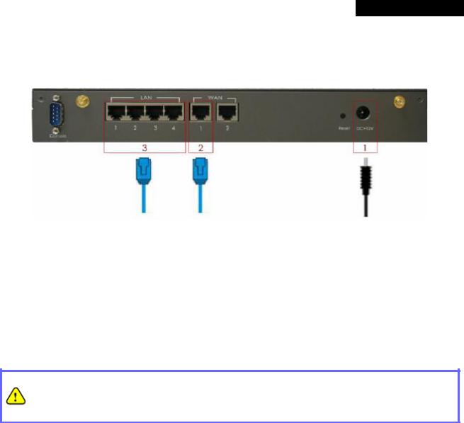
Rear Panel
1.Power Attach the power adaptor here.
2.Reset
∙Press and hold the Reset button for about 5 seconds and the LED status indicator on the front panel will start to blink before restarting the system.
∙Press and hold the Reset button for more than 10 seconds and the LED status indicator on the front panel will start to speed up blinking before resetting the system to default configuration.
3.WAN
∙For connecting to external networks which are not managed by MSG100 via ADSL or Cable Modem, or connecting to a certain LAN of an organization via Switch or Hub.
4.LAN
∙For connecting to the networks managed by MSG100, such as client networking devices.
∙MSG100 supports Service Zone function including Port-Based mode and Tag-Based mode. Under Tag-Based mode, Service Zones are distinguished by VLAN tagging instead of physical LAN ports, and vise versa. By default, the system is in Port-Based mode and all LAN ports are set to the default Service Zone.
5.Console For displaying text data on an extended monitor via a RS-232 DB9 cable.
8 |
© 2008 4IPNET, INC. |
4ipnet MSG100 User’s Manual
3.2 Hardware Installation
Please follow the steps mentioned below to install the hardware of MSG100.
1.Connect the power adapter to the power socket on the rear panel. The Power LED on the front panel should be ON to indicate a proper connection.
2.Connect an Ethernet cable to WAN1 Port on the rear panel. Per your needs, connect the other end of the cable to a networking device such as ADSL modem, cable modem, switch or hub. The WAN1 LED indicator should be ON to indicate a proper connection.
3.Connect an Ethernet cable to any LAN Port on the rear panel. Connect the other end of the cable to a PC for configuring the MSG100 system. The LED indicator should be ON to indicate a proper connection.
∙Please only use the power adapter supplied with the MSG100 package. Using a different power adapter may damage this system.
∙To double verify the wired connection between MSG100 and your switch/router/hub, please also check the LED status indication of these network devices.
9 |
© 2008 4IPNET, INC. |
4ipnet MSG100 User’s Manual
3.3Software Configuration
3.3.1 Instruction of Web Management Interface
4ipnet MSG100 supports web-based configuration. Upon the completion of hardware installation, MSG100 can be configured through a PC by using its web browser with JavaScript enabled such as Internet Explorer version 6.0.
Step 1:
Set DHCP in TCP/IP of the administrator PC to get an IP address dynamically. Connect the PC to any LAN Port of MSG100. An IP address will be assigned to the PC automatically via the MSG100 built-in DHCP server.
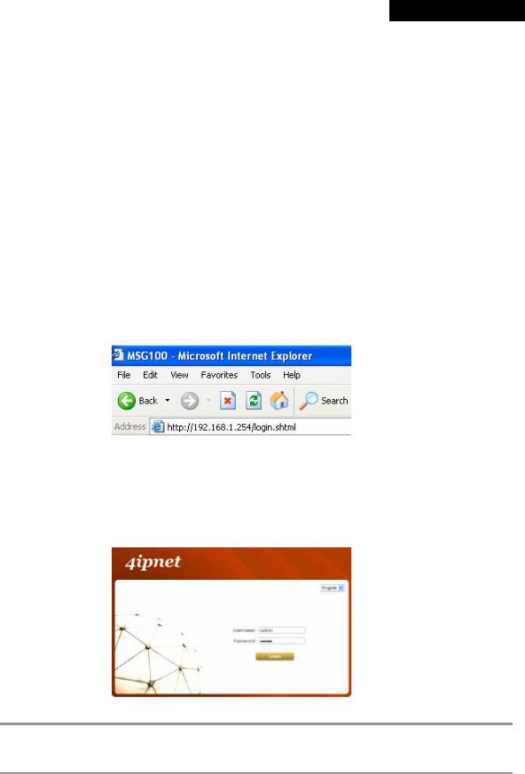
Step 2:
Launch a web browser to access the web management interface of MSG100 by entering “ https://192.168.1.254” (“ https” is used for a secured connection) or “ http://192.168.1.254” in the address field.
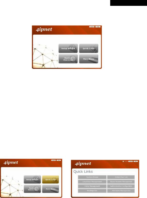
Step 3:
The following Administrator Login Page will then appear. Enter “ admin” (the default value) in the Username and Password fields, and then click Login to log in.
If you are unable to get to the login screen, please check the IP address used. The IP address should 8 Note: be in the same subnet of the default gateway. For using static IP in TCP/IP setting, set a static IP
address such as 192.168.1.x for your network interface, and then open a new browser again.
10 |
© 2008 4IPNET, INC. |
4ipnet MSG100 User’s Manual
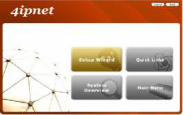
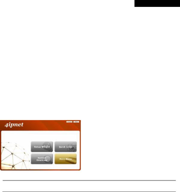
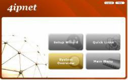
Step 4:
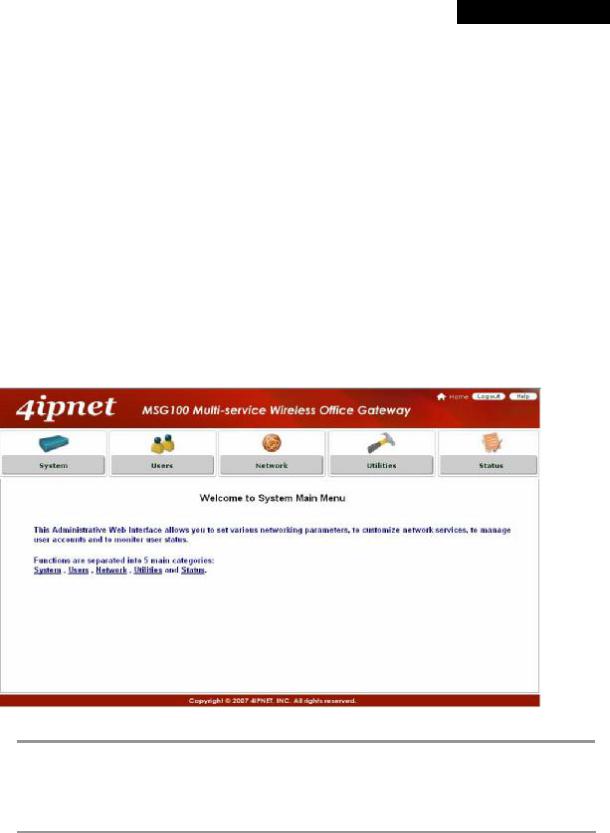
After a successful login, a “Home” page with four links called Setup Wizard, Quick Links, System Overview, and Main Menu will appear.
ØSetup Wizard: provides a four-step quick configuration of the system. Please refer to Section 3.2.2. Quick Configuration for more information.
 à
à 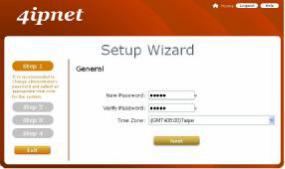
ØQuick Links: provides 8 links for the administrator to access frequently used pages of the web management interface directly, which are System Status, Local User Management, Policy Management, Privilege List, Online User List, Guest Account Management, Authentication Configuration, and Firmware Management.
à
11 |
© 2008 4IPNET, INC. |
4ipnet MSG100 User’s Manual
ØSystem Overview: provides an overview of the system status for the administrator. Certain hyperlinks of associated configuration pages are provided in this page for the administrator to access directly.
 à
à 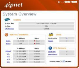
ØMain Menu: provides detailed configuration pages for administrators to configure the system manually. Please refer to Section 4. Main Menu for more information.
à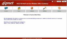
8 Note:
Quick Links and System Overview are not accessible until the system is configured via Setup Wizard.
12 |
© 2008 4IPNET, INC. |
4ipnet MSG100 User’s Manual
3.3.2 Setup Wizard
MSG100 provides a Setup Wizard for quick configuration. The Configuration Wizard comprises of four basic steps. Follow the instructions of Configuration Wizard to enter the required information step by step, save your settings, and restart MSG100. Then, the system is ready to use. The four steps of Configuration Wizard are listed below:
Step I. General
Step 2. WAN1 Interface
Step 3. Local User Account (Optional)
Step 4. Confirm and Restart
Please follow the steps below to complete the Setup Wizard configuration.
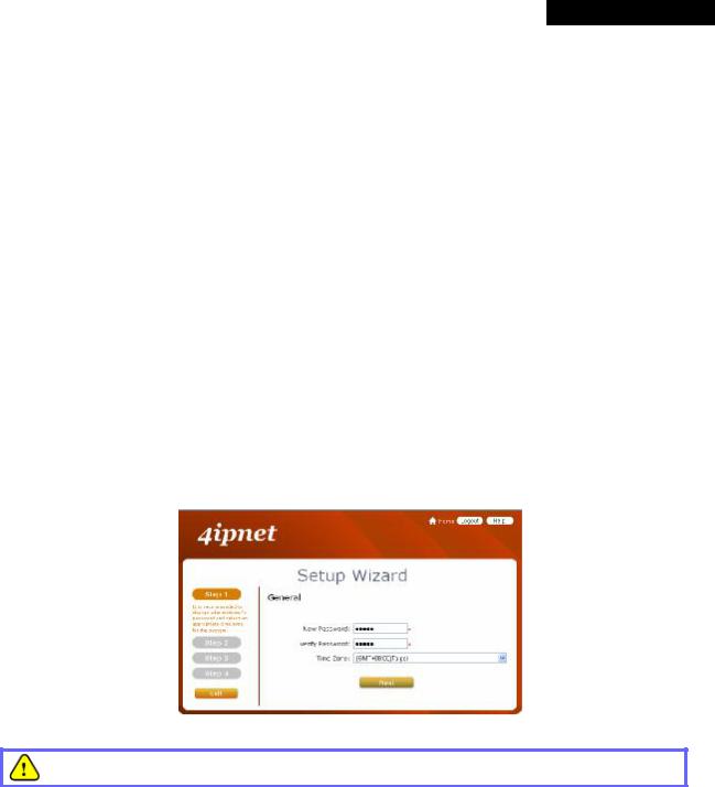
Step 1: General
∙Click the Setup Wizard in the Home page to start the configuration process.
∙Enter a new password in the New Password field, and re-enter it again in the Verify Password field (a maximum of 20 characters and no spaces allowed in between).
∙Select an appropriate time zone from the Time Zone drop-down list box to set up the system time.
∙Click Next to continue.
For security concern, it is strongly recommended to change the administrator's password.
13 |
© 2008 4IPNET, INC. |
4ipnet MSG100 User’s Manual
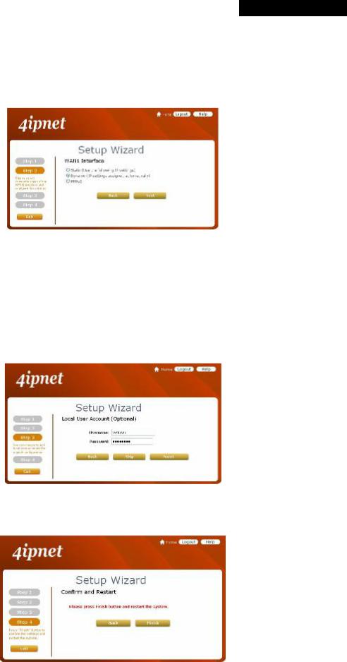
Step 2: WAN1 Interface and Wireless
∙Select a proper type of Internet connection for WAN1 interface from the following three available connections: Static, Dynamic, or PPPoE. Your ISP or network administrator can advise on the connection type available to you. Below depicts an example for Dynamic.
∙Click Next to continue.
Step 3: Local User Account (Optional)
New local accounts can be created and added into the database via this optional function. If local user accounts are not required, click Skip to go directly to Step 4. However, it is recommended to create at least one local user account in order to verify the system‘s readiness upon completion of this Setup Wizard.
∙Enter the Username (e.g. “ testuser” ) and Password (e.g. “ testuser” ) to create a new local account.
∙Click Next to continue.
∙More local accounts can be added by clicking the Back button in Step 4.
Step 4: Confirm and Restart
∙Click Finish to save current settings and restart the system.
14 |
© 2008 4IPNET, INC. |
4ipnet MSG100 User’s Manual
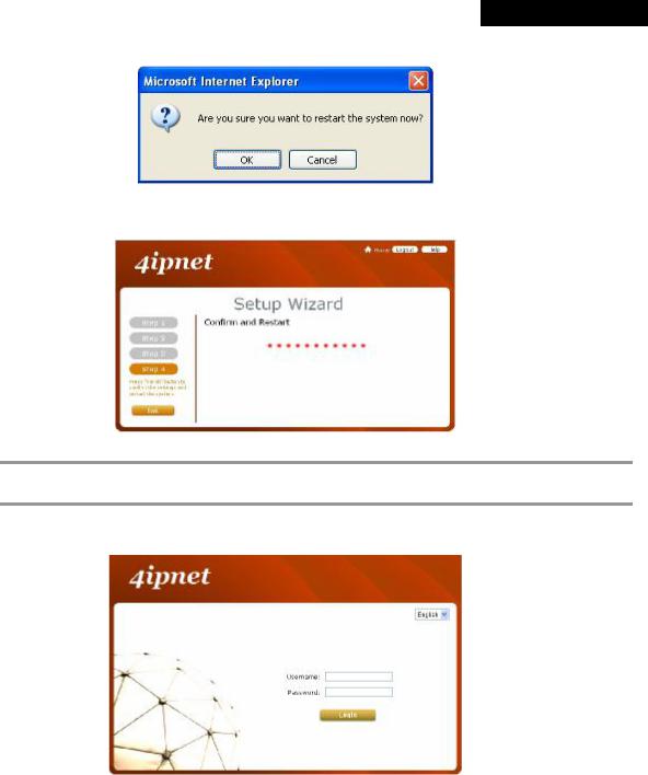
∙A confirmation dialog box will then appear. Click OK to continue.
∙A Confirm and Restart message will appear on the screen during the restarting process. Please do not interrupt the system until the Administrator Login Page appears.
8 Note:
The system is trying to locate a DNS server at this stage. Therefore, a longer startup time is required if the configured DNS cannot be found.
∙When the following Administrator Login Page appears, it means the restart process is now completed.
15 |
© 2008 4IPNET, INC. |
4ipnet MSG100 User’s Manual
3.3.3 User Login Portal Page
In order to be granted network access via MSG100’s controlled port, a user must be authenticated first by entering a correct username and password on the User Login Portal Page. To verify whether the configuration of the new local user account(s) created via the Setup Wizard has been completed successfully:
1.Connect a client device (e.g. laptop, PC) to the LAN1 Port of MSG100. The device will obtain an IP address automatically via DHCP.
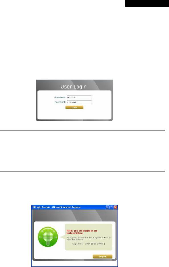
2.Open a web browser on a client device, access any URL, and then the default User Login Page will appear.
3.Enter the Username and Password of a local user account previously generated via Setup Wizard (e.g.
“ test@local” as the Username and “ test” as the Password); then Click Login
1. MSG100 supports multiple authentication options including built-in local user database and external authentication database (e.g. RADIUS). The system will automatically identify which authentication option is used from the full username entered.
8 Note:
2. The format of a full (valid) username is userid@postfix, where “ userid” is the user ID and “ postfix” is the name of the selected authentication option.
3. Exception: The postfix can be omitted only when the default authentication option is used. For example, “ LOCAL” is the default authentication option at this system; therefore, you may enter either “ test” or “ test@local” in the Username field.
Congratulation!
The Login Success Page will appear after a client has successfully logged into MSG100 and has been authenticated by the system. The appearance of Login Success Page means that MSG100 has been installed and configured properly.
16 |
© 2008 4IPNET, INC. |
4ipnet MSG100 User’s Manual
4.Web Interface Configuration
This chapter will guide you through further detailed settings. The following table shows all the UI functions of MSG100.
OPTION |
System |
Users |
Network |
Utilities |
Status |
|
|
|
|
|
|
|
General |
Authentication |
NAT |
Password Change |
System |
|
WAN 1 |
Black List |
Privilege |
Backup & Restore |
Interface |
|
WAN 2 |
Group |
Monitor IP |
System Upgrade |
Routing Table |
FUNCTION |
WAN Traffic |
Policy |
Walled Garden |
Restart |
Online Users |
LAN Port |
Additional |
Proxy Server |
Network Utilities |
User Logs |
|
|
Mapping |
Control |
|||
|
|
|
|
||
|
Service Zones |
|
DDNS |
|
E-mail & SYSLOG |
|
|
|
Client Mobility |
|
|
|
|
|
VPN |
|
|
∙Click Apply to allow the changes you made on the current page to take effect immediately.
∙Sometimes the system may require a restart after clicking Apply. When a restart message
8 Note: appears, the system must be restarted for the settings to take effect. Restart can be done till all configurations are completed.
∙ All on-line users will be disconnected during restart.
17 |
© 2008 4IPNET, INC. |
4ipnet MSG100 User’s Manual
4.1 System Configuration
4.1 System
This section includes the following functions: General, WAN1, WAN2, WAN Traffic, LAN Port Mapping, and
Service Zones.
4.1.1 General
Main information about MSG100 is shown on this page, including System Name, Internal Domain Name, Homepage Redirect URL, User Log Access IP Address, Management IP Address List, SNMP, HTTPS Protected Login, and Network Time Protocol (NTP) Server.
18 |
© 2008 4IPNET, INC. |
4ipnet MSG100 User’s Manual
ŸSystem Name: Set the name of the system or use the default.
ŸInternal Domain Name: A fully qualified domain name (FQDN) of the system. The domain name entered here will be shown at the top left of the Login Success page. In addition, when HTTPS is enabled, entering the domain name of the uploaded certificate will not only change the URL of the User Login page, but also increase login speed. For example, if the Internal Domain Name is configured as “ ashop.com” , the URL of the User Login page will be https://ashop.com/loginpages/login.shtml.
ŸHomepage Redirect URL: Enter the URL of a Web server as the homepage. When Local VPN is disabled at this system, after a successful login, users will be directed to this homepage, such as http://www.google.com, regardless of the original homepage set in their computers.
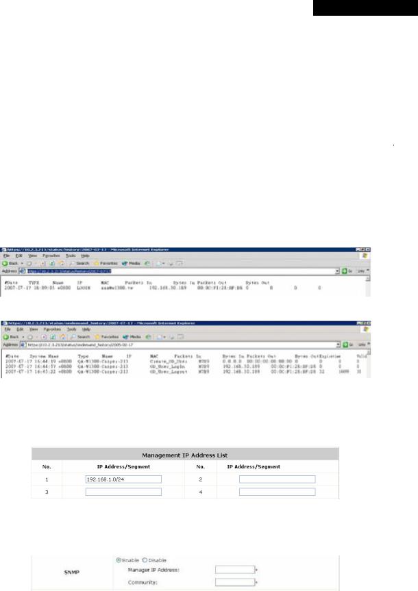
ŸUser Log Access IP Address: Specify the IP address of an external billing system to access the system's user logs. Only the specified billing system can directly access the system's user logs in text format via a Web browser. For example, if the access interface of MSG100 is “10.30.1.213”, the user logs can be found in following URLs.
n Traffic History https://10.2.3.213/status/history/2007-07-17
n On-demand History https://10.2.3.213/status/ondemand_history/2007-07-17
ŸManagement IP Address List: Set the IP range where the web management interface of MSG100 can be connected via its WAN and/or LAN ports. For example, “192.168.1.0/24” means that as long as you are within the IP range between 192.168.1.0 and 192.168.1.255, you can reach the management interface.
ŸSNMP: MSG100 supports SNMPv2. If this function is enabled, the specified SNMP server can access the Management Information Base (MIB) of the system.
19 |
© 2008 4IPNET, INC. |
4ipnet MSG100 User’s Manual
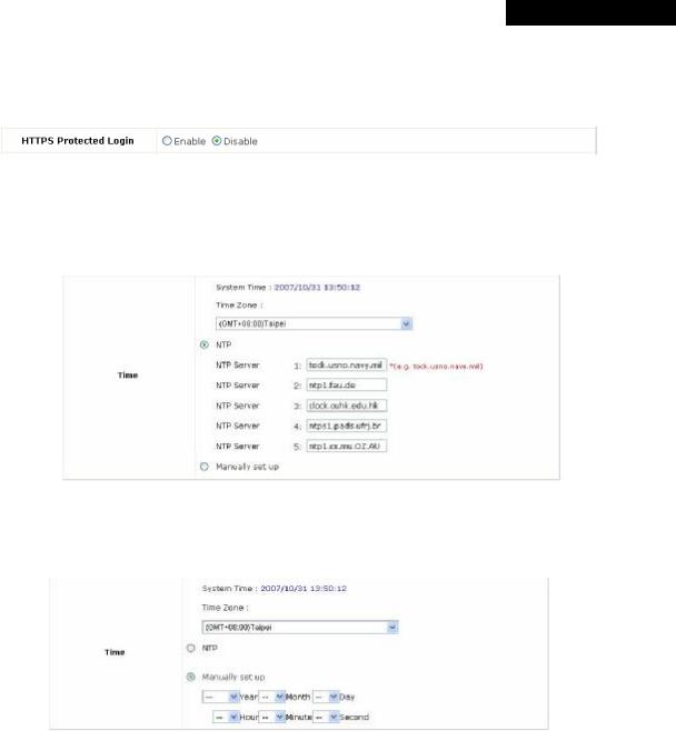
ŸHTTPS Protected Login: The system supports HTTPS (encrypted) and HTTP (non-encrypted) for clients to log into the system. When this function is enabled, the Secured Socket Layer (SSL) will be activated and implemented into the Web-based user login page.
ŸTime: The system time can be set up manually or synchronized with remote NTP (Network Time Protocol) servers. It supports up to five NTP servers. When NTP is enabled, the information of at least one NTP server must be provided.
The system time can also be set up manually by selecting Manually set up. Then select the date and time from the drop-down list box.
20 |
© 2008 4IPNET, INC. |
4ipnet MSG100 User’s Manual
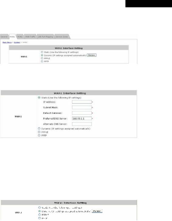
4.1.2 WAN1
There are 4 connection types supported on the WAN1 Port: Static, Dynamic, PPPoE and PPTP.
ŸStatic (Use the following IP Settings): Select this option to specify a static IP address for the WAN1 port manually when a static IP address is available for MSG100. The fields with red asterisk are required.
ØIP Address: The IP address of the WAN1 port.
ØSubnet Mask: The subnet mask of the WAN1 port.
ØDefault Gateway: The gateway of the WAN1 port.
ØPreferred DNS Server: The primary DNS Server of the WAN1 port.
ØAlternate DNS Server: The substitute DNS Server of the WAN1 port. This is optional.
ŸDynamic (IP settings assigned automatically): This option can be selected when there is a DHCP server located on the network that MSG100 is connected to. Click Renew to get an IP address automatically.
21 |
© 2008 4IPNET, INC. |
4ipnet MSG100 User’s Manual
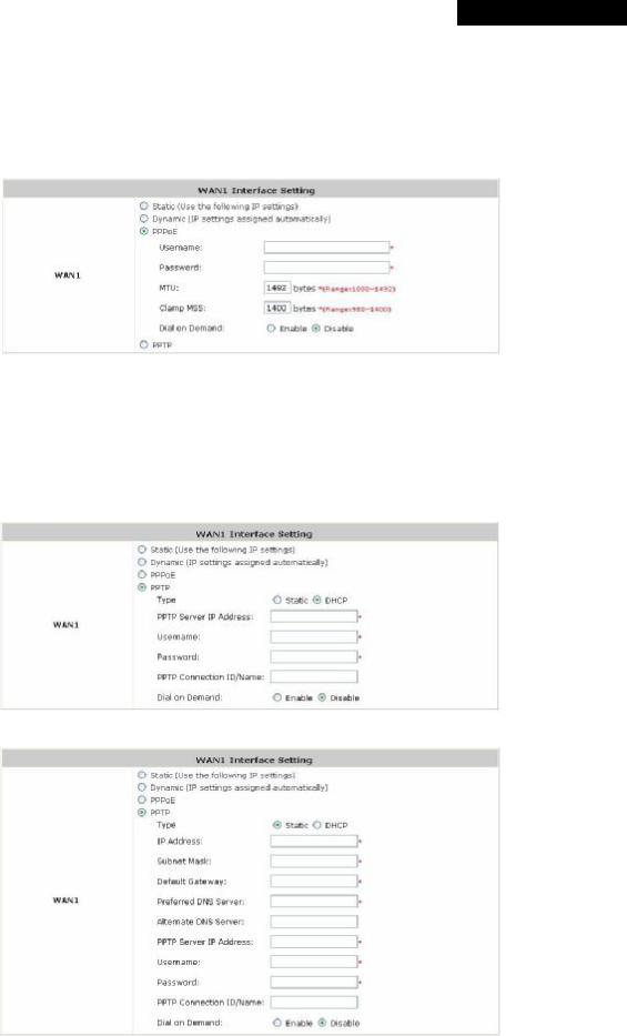
ŸPPPoE: Select this option when PPPoE is the connection protocol provided by your ISP.
To properly configure PPPoE connection type, set the Username, Password, MTU and Clamp MSS. When Dial on Demand is enabled, the Maximum Idle Time field is required to be filled in. The system will disconnect itself from the Internet automatically when the Maximum Idle Time is reached.
ŸPPTP: Select this option when PPTP is the connection protocol provided by your ISP.
When Dial on Demand is enabled, the Maximum Idle Time field is required to be filled in. The system will disconnect itself from the Internet automatically when the Maximum Idle Time is reached.
There are two connection types available, Static or DHCP.
Ø Static: Select Static to specify the IP address of the PPTP Client manually.
ØDHCP: Select DHCP to get the IP address automatically..
22 |
© 2008 4IPNET, INC. |
4ipnet MSG100 User’s Manual
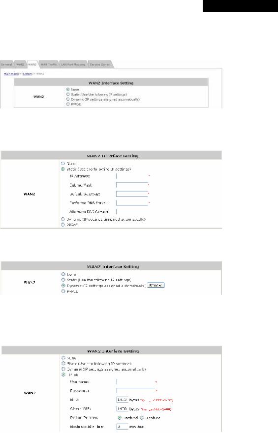
4.1.3 WAN2
WAN2 can be disabled when selecting None. When WAN2 Port is enabled, it supports 3 connection types: Static,
Dynamic and PPPoE.
ŸNone: The WAN2 Port is disabled.
ŸStatic (Use the following IP Settings): Select this option to specify a static IP address for the WAN2 port manually when a static IP address is available for MSG100. The fields with red asterisk are required.
ŸDynamic (IP settings assigned automatically): This option can be selected when there is a DHCP server located on the network that MSG100 is connected to. Click Renew to get an IP address automatically.
ŸPPPoE: Select this option when PPPoE is the connection protocol provided by your ISP.
To properly configure PPPoE connection type, set the Username, Password, MTU and Clamp MSS. When Dial on Demand is enabled, the Maximum Idle Time field is required to be filled in. The system will disconnect itself from the Internet automatically when the Maximum Idle Time is reached.
23 |
© 2008 4IPNET, INC. |
4ipnet MSG100 User’s Manual
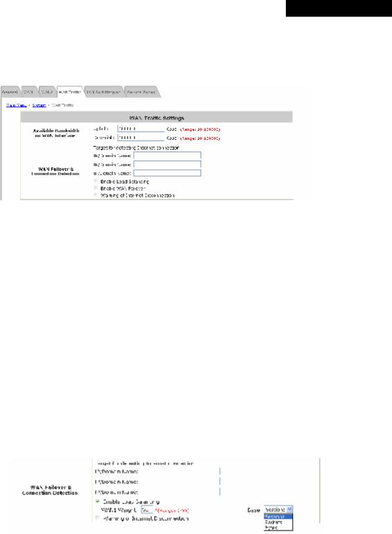
4.1.4 WAN Traffic
MSG100 supports uplink/downlink bandwidth management features, including Load Balancing and WAN Failover, and Connection Detection.
∙Available Bandwidth on WAN Interface:
ØUplink Bandwidth: The maximum uplink bandwidth of the WAN interface to be shared by clients. The same setting will be applied to WAN1 and WAN2.
ØDownlink Bandwidth: The maximum downlink bandwidth of the WAN interface to be shared by clients. The same setting will be applied to WAN1 and WAN2.
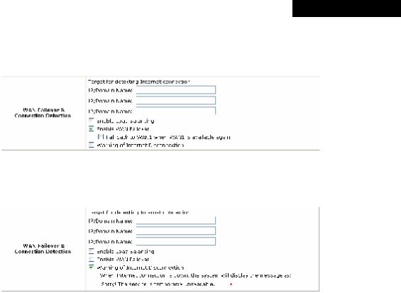
∙WAN Failover & Connection Detection: MSG100 supports WAN Failover, Load Balancing and the ability to detect WAN connection.
ØTarget for detecting Internet connection: Enter the IP address or domain name of up to three targets to which the system will send packets for detecting Internet connection status. If there is a problem in the connection in the WAN port, and the specified IP address(es) or domain name(s) cannot be reached, there will be a warning message appearing on clients’ screens. To enable WAN Failover, at least one target must be configured.
ØEnable Load Balancing: MSG100 supports outbound load balancing. Select to enable the system’s Load Balancing function. The system will distribute traffics to WAN1 and WAN2 based on the weight ratio assigned; the weight ratio can be based on Sessions, Packets or Bytes. When this function is enabled, the WAN Failover check box will disappear because WAN Failover is covered by Load Balancing.
o WAN1 Weight: Enter a value ranging from 1~99. The default value is 50.
oBase: Three Base types can be selected from: Sessions, Packets or Bytes. Packets and Bytes are based on historic downlink data. New connection sessions will be distributed between WAN1 and WAN2 based on the Base selected and WAN1 Weight set.
24 |
© 2008 4IPNET, INC. |
4ipnet MSG100 User’s Manual
ØEnable WAN Failover: Select to enable the WAN Failover function to ensure continuous uptime for Internet connection. Furthermore, select “Fall back to WAN1 when WAN1 is available again” to allow the traffic goes back to WAN1 when WAN1 becomes active again after a disconnection.
ØWarning of Internet Disconnection: MSG100 supports Internet disconnection detection feature. When this function is enabled, a text box will appear for the administrator to enter a warning message. This warning message will appear on clients' screens when Internet connection is down.
25 |
© 2008 4IPNET, INC. |
4ipnet MSG100 User’s Manual
4.1.5 LAN Port Mapping
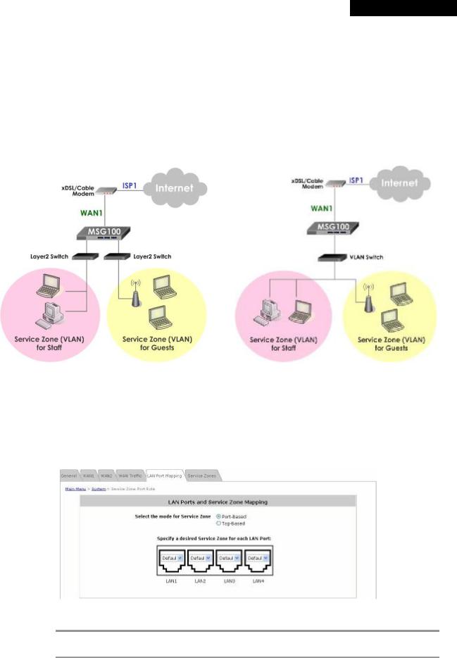
MSG100 supports multiple Service Zones in either of the two VLAN modes, Port-Based or Tag-Based, but not concurrently. In Port-Base mode, each LAN port can only serve traffic from one Service Zone as each Service Zone is identified by physical LAN ports. In Tag-Based mode, each LAN port can serve traffic from any Service Zone as each Service Zone is identified by VLAN tags carried within message frames. By default, the system is in Port-Based mode with Service Zone 1 (Default Service Zone) enabled and all LAN ports are mapped to Default Service Zone. Compare two figures below to see the differences.
|
Port-Based |
|
Tag-Based |
It is recommended that the administrator decides which mode is better for a multiple-service-zone deployment before proceeding further with the system configuration. Settings for the two VLAN modes are slightly different, for example, the VLAN Tag setting is required for Tag-Based mode.
∙Select the mode for Service Zone: Select a VLAN mode, either Port-Based or Tag-Based.
8 Note:
The switches deployed under MSG100 in Port-Based mode must be Layer 2 switches only. The switch deployed under MSG100 in Tag-Based mode must be a VLAN switch only.
26 |
© 2008 4IPNET, INC. |
4ipnet MSG100 User’s Manual
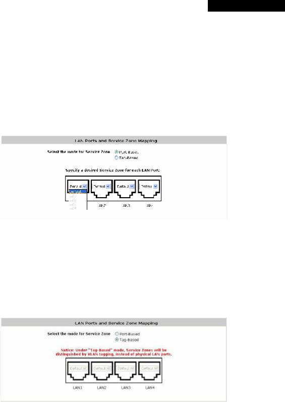
ØPort-Based: When Port-Based mode is selected, traffic from different virtual Service Zones will be distinguished by physical LAN ports. Each LAN port can be mapped to a Service Zone in the form of a many-to-one mapping between ports and Service Zones.
o Specify a desired Service Zone for each LAN Port: For each LAN port, select a Service Zone to which the LAN port is to be mapped from the drop-down list box.
By factory default, all LAN ports are mapped to Default Service Zone; therefore, the administrator can enter the web management interface via any LAN port upon the first power up of the system. From the drop-down list box, all disabled Service Zones are gray-out; to activate any desired Service Zone, please configure the desired Service Zone under the Service Zone tab and enable its Service Zone Status (refer to Section 4.1.6. Service Zones).
ØTag-Based: When the Tag-Based mode is selected, traffic from different virtual Service Zones will be distinguished by VLAN tagging, instead of by physical LAN ports.
Select Tag-Based and then click Apply to activate the Tag-Based VLAN function. When a restart message screen appears, do NOT restart the system until you have completed the configuration under the Service Zones tab first.
For more information on enabling Tag-Based VLAN and configuring Service Zones, please refer to
Appendix B. Service Zone – Deployment Example.
27 |
© 2008 4IPNET, INC. |
 Loading...