

OWL500/510
V1 . 00

Quick Installation Guide
i
O W L 5 0 0 / 5 1 0 L o n g R a n g e O u t d o o r C P E / A P / B r i d g e ENGLISH
Copyright N otic e
This document is protected by U S A copyrig ht l a w s a nd other l a w s a nd is the property of
4 I P N E T, I N C . Y ou ma y not copy, reproduce, distribute, publ ish, displ a y, perf orm, or
modif y a ny pa rt of this publ ica tion in a ny f orm or by a ny mea ns w ithout prior w ritten
permission f rom 4 I P N E T, I N C . Y ou ma y not a l ter or remov e a ny copyrig ht or other notice
f rom copies of the content. Al l other bra nd a nd product na mes a re cl a imed or
reg istered ma rk s of their respectiv e compa nies or org a niz a tions.
Al l rig hts reserv ed.

Quick Installation Guide
ii
O W L 5 0 0 / 5 1 0 L o n g R a n g e O u t d o o r C P E / A P / B r i d g e ENGLISH
N o t e
The respective FCC ID for This document serves only as a sample manual and QIG for this sample unit. The
respective FCC ID for O W L 5 00/ O W L 5 1 0 w ill b e V Z 9090003 , application in prog ress in J uly 2 009.

Quick Installation Guide
O W L 5 0 0 / 5 1 0 L o n g R a n g e O u t d o o r C P E / A P / B r i d g e ENGLISH
Preface Pack ag e C o n t en t s
The 802.11 b/g compliant OWL500/510 is a Long
Range Outdoor CPE/AP/Bridge device that can be
used for dual purposes. First, it can be deployed as
a traditional fixed wireless Access Point (AP).
Secondly, it can be used as a Customer Premises
Equipment (CPE) that connects to the outdoor
wireless network of Wireless Internet Service
Provider (WISP).
The metal sealed OWL500/510 is compact in size
and weatherproof. Coming with a mounting kit, it
can be mounted on a pole or wall. It is suitable for
both indoor and outdoor usage with its 500mW
1. OWL500/510 x 1
2. Quick Installation Guide (QIG) x 1
3. CD-ROM
(with User’s Manual and QIG)
4. Power Sourcing Equipment (PSE) with
AC cable x 1
5. Mounting Kit x 1
It is recommended to keep the original
packing material for possible future shipment
when repair or maintenance is required. Any
returned product should be packed in its
original packaging to prevent damage during
delivery.
x 1
output power, which is higher than a typical indoor
AP (100mW).
This Quick Installation Guide (including FAQ
Instruction Guide) provides instructions for getting
started with OWL500/510.
- 1 -
Quick Installation Guide
System Overview
O W L 5 0 0 / 5 1 0 L o n g R a n g e O u t d o o r C P E / A P / B r i d g e ENGLISH
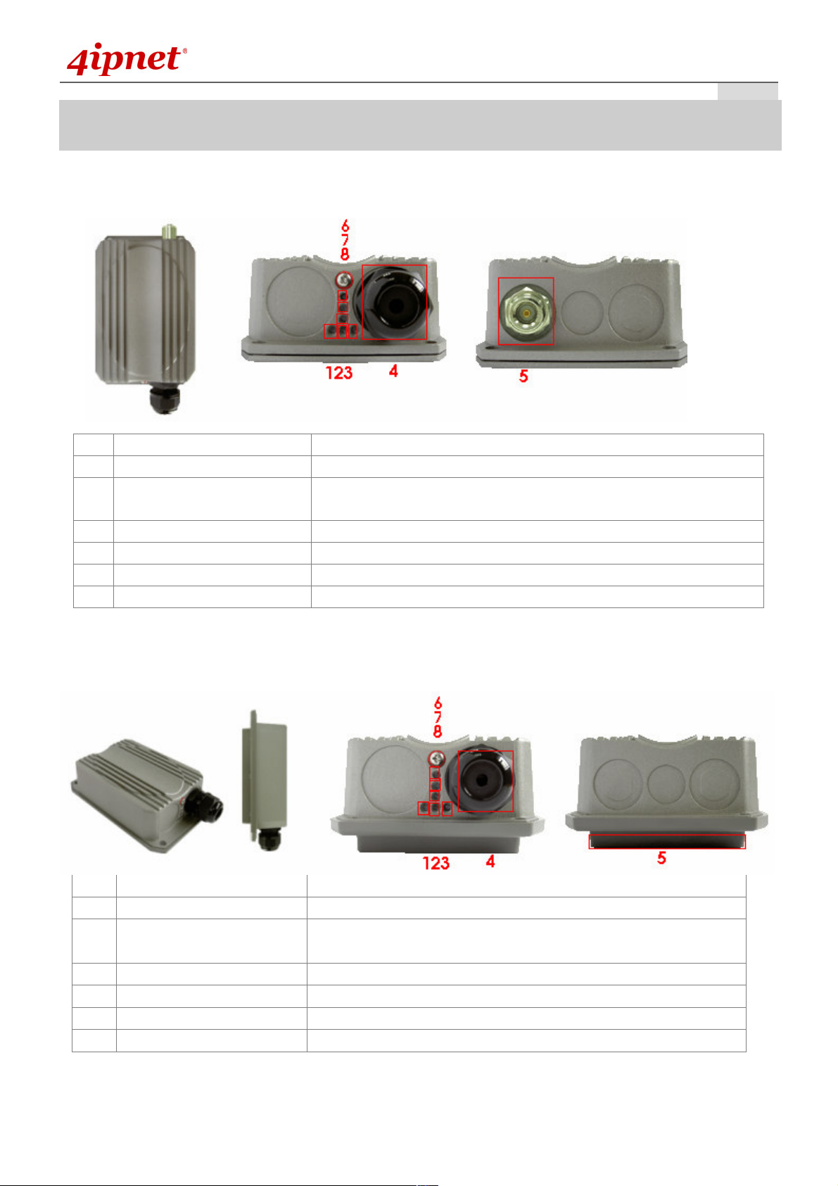
OWL500
1 WLAN Green LED ON indicates system ready
2 Wireless Signal Strength For showing the signal strength situation
3 Ethernet Green LED ON indicates connection, OFF indicates no connection,
4 PoE Connector For connecting to the Power Sourcing Equipment (PSE)
5 N-type Connector For connecting to an antenna
6 Power Red LED ON indicates power on, and OFF indicates power off
7, 8 Wireless Signal Strength For showing the signal strength situation (7: Yellow; 8: Green)
and BLINKING indicates transmitting data.
OWL510
1 WLAN Green LED ON indicates system ready
2 Wireless Signal Strength For showing the signal strength situation
3 Ethernet Green LED ON indicates connection, OFF indicates no
connection, and BLINKING indicates transmitting data.
4 PoE Connector For connecting to the Power Sourcing Equipment (PSE)
5 Built-in patch antenna 10 dBi (Horizontal: 110 degree; Vertical: 60 degree)
6 Power Red LED ON indicates power on, and OFF indicates power off
7, 8 Wireless Signal Strength For showing the signal strength situation (7: Yellow; 8: Green)
- 2 -
Quick Installation Guide
O W L 5 0 0 / 5 1 0 L o n g R a n g e O u t d o o r C P E / A P / B r i d g e ENGLISH
H a rd wa re I n sta l l a tio n
OWL500/510
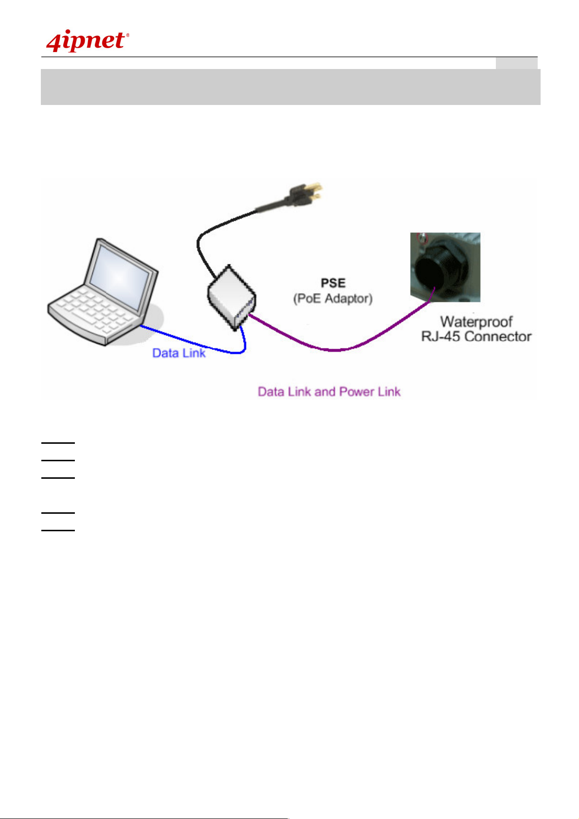
The following diagram is a basic network topology which can be used for testing and configuring the
OWL500/510.
Installation Steps:
Step 1. Connect an N-type antenna to the N-type connector (applicable for OWL500/510 only).
Step 2. Connect the PSE (POWER & DATA OUT) to the PSE 1 connector on the lower panel.
Step 3. Connect one end of an Ethernet cable to the PSE 2 connector on the lower panel and the other end
to a computer.
Step 4. Connect the power cord to the PSE.
Step 5. Power on the PSE in order to supply power to the OWL500/510.
- 3 -

Quick Installation Guide
O W L 5 0 0 / 5 1 0 L o n g R a n g e O u t d o o r C P E / A P / B r i d g e ENGLISH
G ettin g Sta rted
4ipnet OWL500/510 supports web-based configuration. OWL500/510 is a dual-mode system, AP Mode as the
default mode for the first time entering the system, which also can be configured as either an access point (AP
Mode) or a gateway (CPE Mode) based on your needs. It is required to follow the respective installation
procedures provided to properly set up the desired mode for this system.
• Default IP Address of Web Management Interface:
The default IP address and Subnet Mask for the AP mode and CPE mode are as follows:
Mode AP Mode CPE Mode
IP Address
Subnet Mask
1 9 2 . 1 6 8 . 1 . 1 1 9 2 . 1 6 8 . 1 . 1
2 5 5 . 2 5 5 . 2 5 5 . 0 2 5 5 . 2 5 5 . 2 5 5 . 0
• Default User Name and Password:
There is only one management account for AP mode, root. In addition, there are two system management
accounts for CPE mode to maintain the system, root and admin, and each has different levels of management
capabilities. The root account is empowered with full privileges while the admin account is with partial ones.
The default user name and password for both the root and admin account are as follows:
Mode AP Mode CPE Mode
Management
Account
User Name
Password
Root
Account
Root
Account
Admin
Account
root root a dmin
a dmin a dmin a dmin
- 4 -

Quick Installation Guide
<AP Mode—Default Mode>
O W L 5 0 0 / 5 1 0 L o n g R a n g e O u t d o o r C P E / A P / B r i d g e ENGLISH
Step 1:
Set a static IP address on the same subnet mask as OWL500/510 in TCP/IP of the administrator PC, such as
the following example. Do not duplicate the IP address used here with the IP address of OWL500/510 or any
other devices within the same network.
>> Example of IP Segment:
The valid range of IP address is 1 ~ 254. However, 1 must be avoided as it is already used by OWL500/510.
Below depicts an example of using 100 (the underlined value can be changed as desired).
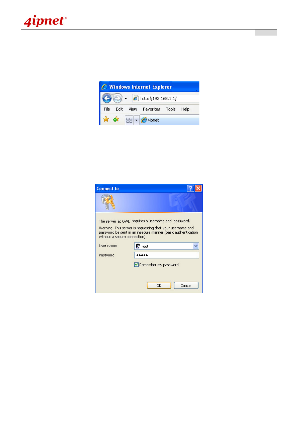
Step 2: Launch Web Browser
Launch a web browser to access the web management interface of AP mode by entering the default IP
address, http://192.168.1.1/, in the URL field, and then press Enter.
IP Segment Setup for Administrator PC
IP Address: 192.168.1.100
Subnet Mask: 255.255.255.0
Using an incorrect default IP address will result in no Login page
shown in the web browser. Please make sure a correct IP
address is used for the desired mode.
Step 3: System Login
The system manager Login Page will then appear.
Enter “root” in the User name field and “admin” in the Password field, and then click OK to log in.
- 5 -
Quick Installation Guide
O W L 5 0 0 / 5 1 0 L o n g R a n g e O u t d o o r C P E / A P / B r i d g e ENGLISH
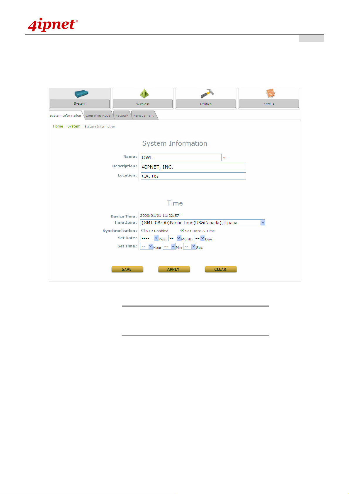
Step 4: Login Success
After a successful login to OWL500/510, a System Overview page of web management interface will appear,
To logout, simply click on the Logout button at the upper right hand corner of the interface.
By default, AP mode is enabled. Therefore, the
Note:
administrator must access the system via the AP
mode login page for the first time. The administrator is
then able to switch between modes afterwards.
- 6 -
Quick Installation Guide
O W L 5 0 0 / 5 1 0 L o n g R a n g e O u t d o o r C P E / A P / B r i d g e ENGLISH
<CPE Mode>
Step 1: Launch Web Browser
Launch a web browser to access the web management interface of CPE mode by entering the default IP
address, http://192.168.1.1/, in the URL field, and then press Enter.
Step 2: System Login
The system manager Login Page will then appear.
Enter “root” in the User name field and “admin” in the Password field, and then click OK to log in. Below
depicts an example of using the root manager account.
- 7 -

Quick Installation Guide
O W L 5 0 0 / 5 1 0 L o n g R a n g e O u t d o o r C P E / A P / B r i d g e ENGLISH
Step 3: Login Success
After a successful login to OWL500/510, a System Overview page of web management interface will appear.
To logout, simply click on the Logout button at the upper right hand corner of the interface.
- 8 -
Quick Installation Guide
C o mmo n Settin g s
<AP Mode – Default Mode>
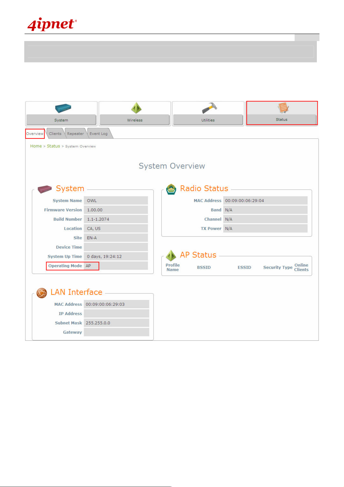
Step 1: Mode Confirmation
O W L 5 0 0 / 5 1 0 L o n g R a n g e O u t d o o r C P E / A P / B r i d g e ENGLISH
Ensure the Operating Mode is currently in AP mode.
Click on the Status button and then select the System Overview tab. The Operating Mode is at the
System section on the System Overview page.
- 9 -
Quick Installation Guide
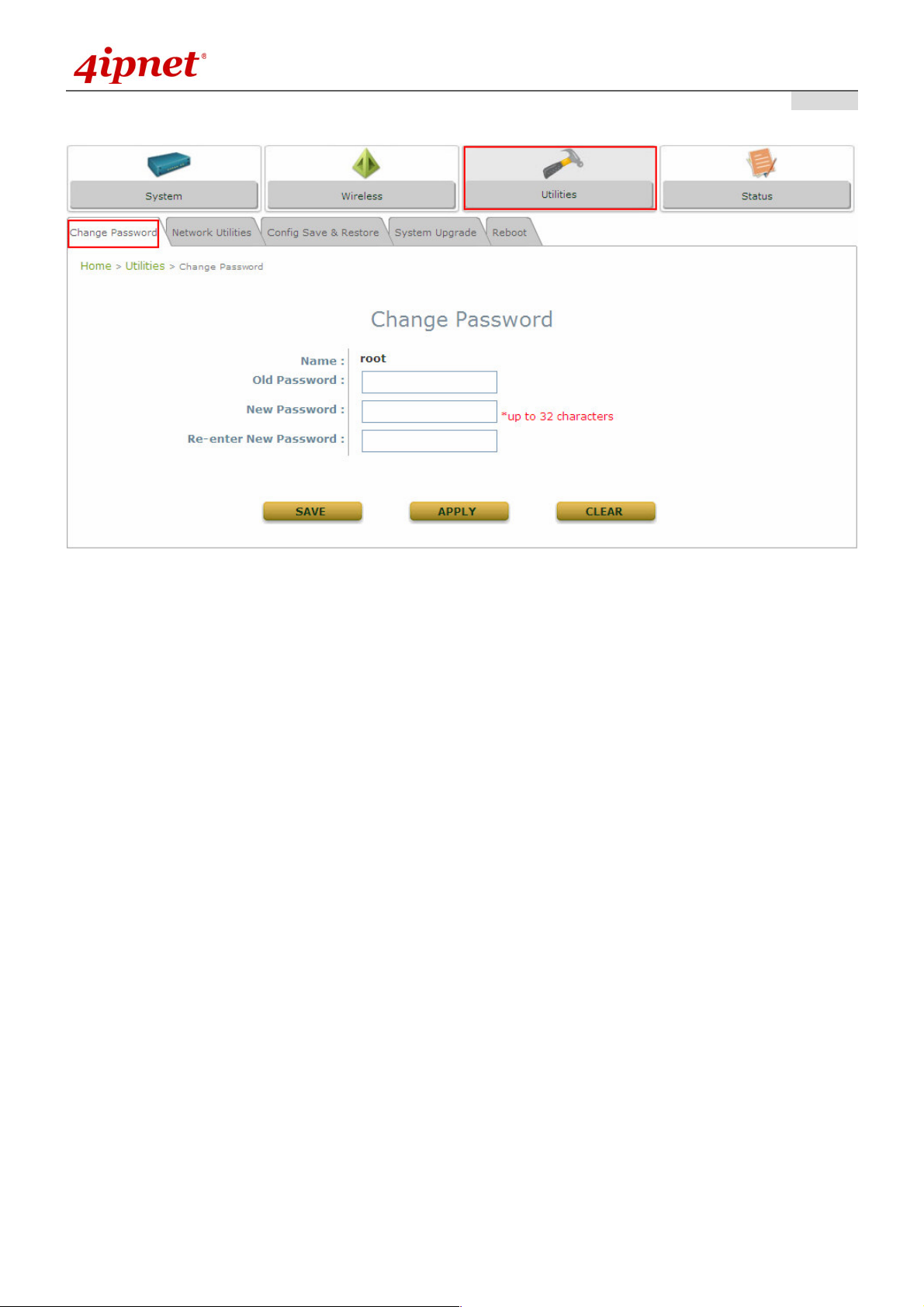
Step 2: Change Password
O W L 5 0 0 / 5 1 0 L o n g R a n g e O u t d o o r C P E / A P / B r i d g e ENGLISH
Click on the Utilities button and then select the Password tab.
Enter a new password in the New Password field and retype it in the Re-enter New Password field.
Click Save to save the changes.
- 1 0 -

Quick Installation Guide
Step 3: Network Settings
O W L 5 0 0 / 5 1 0 L o n g R a n g e O u t d o o r C P E / A P / B r i d g e ENGLISH
Settings here are for example only
Click on the System button and then select the Network tab.
Enable Static, and then enter the related information in the fields marked with red asterisks.
Click Save to save the settings.
- 1 1 -

Quick Installation Guide
Step 4: SSID Settings
O W L 5 0 0 / 5 1 0 L o n g R a n g e O u t d o o r C P E / A P / B r i d g e ENGLISH
Click on the Wireless button and then select the General tab.
Band: Select an appropriate band from the drop-down list box.
Click on the Wireless button and then select the General tab.
Band: Select an appropriate band from the drop-down list box.
SSID: Enter a SSID for the system in the SSID field or use the default. SSID (Service Set Identifier) is a
unique identifier used for networking devices to get associated with OWL500/510.
- 1 2 -

Quick Installation Guide
Note:
Band and SSID are required; other fields are optional.
Click Save to save the settings.
Step 5: Security Settings
O W L 5 0 0 / 5 1 0 L o n g R a n g e O u t d o o r C P E / A P / B r i d g e ENGLISH
Click on the Wireless button and then select the Security tab.
Select the desired VAP Profile and Security Type from the drop-down list boxes. The above figure depicts
an example of selecting VAP-1 and WEP.
Enter the information required in the blank fields.
You must use the same information provided here to configure the network devices that are to be
associated with OWL500/510.
Click Apply to activate all settings configured so far.
Congratulations!
The AP mode is now successfully configured.
- 1 3 -

Quick Installation Guide
<CPE Mode>
Step 1: Mode Confirmation
O W L 5 0 0 / 5 1 0 L o n g R a n g e O u t d o o r C P E / A P / B r i d g e ENGLISH
Ensure the Operating Mode is currently in CPE mode.
Click on the Status button and then select the System Overview tab. The Operating Mode is at the
System section on the System Overview page.
- 1 4 -

Quick Installation Guide
Step 2: Change Password
O W L 5 0 0 / 5 1 0 L o n g R a n g e O u t d o o r C P E / A P / B r i d g e ENGLISH
Click on the Utilities button and then select the Password tab.
Change Root Account Password
•
Enter the old password in the Old Password field; default password is “admin”.
•
Enter a new password in the New Password field and retype it in the Re-enter New Password field.
Change Admin Account Password
•
Enter a new password in the New Password field and retype it in the Re-enter New Password field.
Click Save to save the changes.
- 1 5 -

Quick Installation Guide
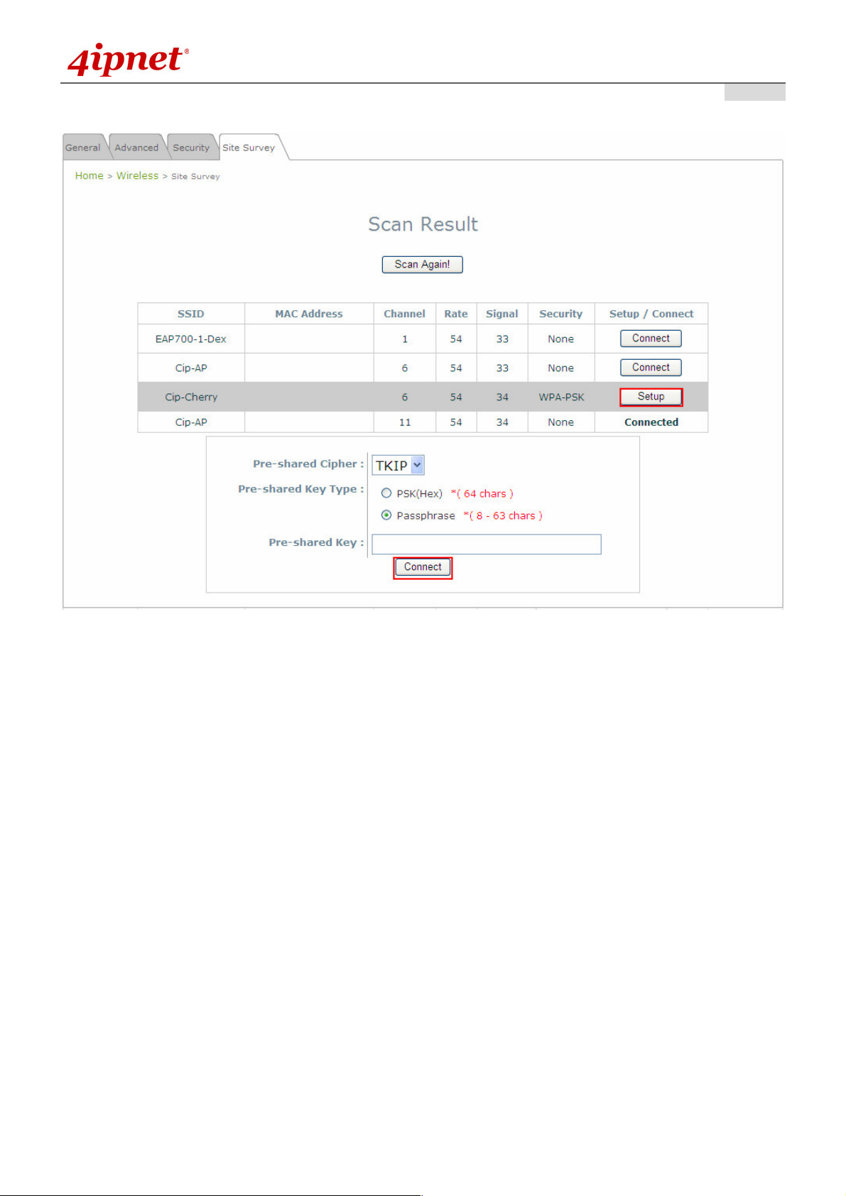
Step 3: Site Survey
O W L 5 0 0 / 5 1 0 L o n g R a n g e O u t d o o r C P E / A P / B r i d g e ENGLISH
The scan result displayed here is an example only.
Click on the Wireless button and then select the Site Survey tab.
The system will automatically scan and display all APs in its coverage area.
Click Scan Again if the APs to be associated with are not listed on the Scan Result list.
Step 4: Select AP to be Associated
Select an AP to be associated with from the Scan Result list provided in Step 3.
- 1 6 -
Quick Installation Guide
Step 5: Security Settings
O W L 5 0 0 / 5 1 0 L o n g R a n g e O u t d o o r C P E / A P / B r i d g e ENGLISH
The above figure depicts an example of selecting AP2 (encrypted via WEP security type).
Click Setup of AP2, and then a related encryption configuration box will appear.
Enter the information required in the configuration box. Information to be entered must be exactly the
same as configured in this AP2.
Click Save to save the settings.
- 1 7 -
Quick Installation Guide
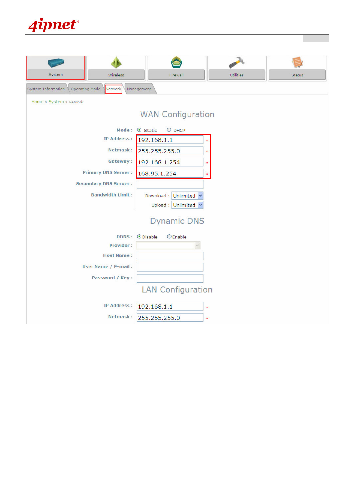
Step 6: Network Interface Configuration
O W L 5 0 0 / 5 1 0 L o n g R a n g e O u t d o o r C P E / A P / B r i d g e ENGLISH
Settings here are for example only
Click on the System button and then select Network tab.
Enable Static, and then enter the related information in the fields marked with red asterisks.
Click Save to save the settings.
Step 7: LAN Configuration
Click on the System button and then select the Network tab.
The LAN Configuration section is on the same page as the WAN Configuration section.
Enter the IP Address and Netmask of the LAN port.
Click Apply to activate all settings configured so far.
Congratulations!
The CPE mode is now successfully configured.
- 1 8 -

Quick Installation Guide
O W L 5 0 0 / 5 1 0 L o n g R a n g e O u t d o o r C P E / A P / B r i d g e ENGLISH
After OWL500/510's network configuration completes, please remember to change the IP Address of
your PC Connection Properties back to its original settings in order to ensure that your PC functions
properly in its real network environments.
It is strongly recommended to make a backup copy of configuration settings.
For further configuration and backup information, please refer to the User’s Manual.
P / N : V 1 002 009092 0
- 1 9 -
 Loading...