


3DR Y6 DIY Kit
DIY
KITS
Y6
Thank you for purchasing a
3DR Y6 DIY Kit!
These instructions will guide
you through assembling and
wiring your new autonomous
multicopter.
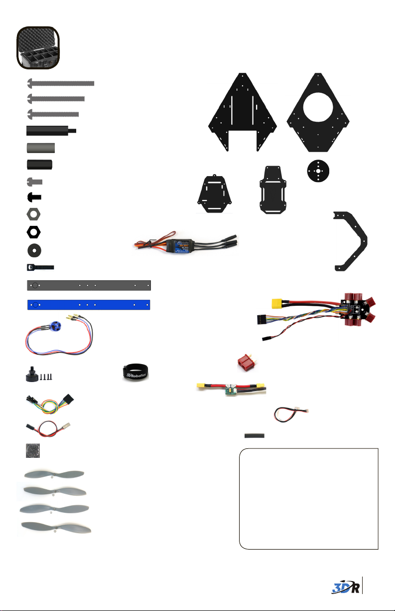
CONTENTS
35 mm steel bolts (3)
30 mm steel bolts (2)
25 mm steel bolts (20)
30 mm threaded spacers (8)
19 mm hollow spacers (13)
18 mm threaded spacers (12)
Your 3DR Y6 Kit contains:
Top plate
Bottom plate
6 mm steel bolts (12)
5 mm nylon bolts (40)
Metal nuts (23)
Nylon nuts (8)
Thumb nuts (5)
11” zip ties (6)
850 Kv motors with
bullet connectors (6)
Option: 880 Kv motors
Motor collets (4)
Six-wire RC receiver cable
Two-wire RC receiver cable
Double-adhesive foam mounting squares (4)
10 x 4.7 SFP (pusher) propellers (2)
10 x 4.7 SF (normal) propellers (1)
11 x 4.7 SFP (pusher) propellers (1)
11 x 4.7 SF (normal) propellers (2)
You will also need:
» Phillips screwdriver (small)
» 5.5 mm (7/32) wrench
» Double-sided foam mounting tape
APM plate
Electronic speed
controllers (6)
Black arm (1)
Blue arm (2)
Battery straps (2)
These instructions require some minor
soldering. If you’re unfamiliar with
soldering, our friends at Sparkfun have
some great tutorials that can get you
started, including this comic:
learn.sparkfun.com/curriculum/42.
For an example of exactly what you’ll
be doing for this assembly (soldering
Deans connectors to ESCs), check out
this video: youtu.be/3LJIQeKuLLU.
» 2 mm (5/64) hex wrench
» Soldering equipment
» Blue threadlocking compound
Co-axial motor
mounting plates (6)
Accessory
plate
C-type landing gear
plates (6)
Power distribution board
Deans connectors - male (6)
Power module with XT60
connectors
6-position power
module cable
Heat shrink tubing
1
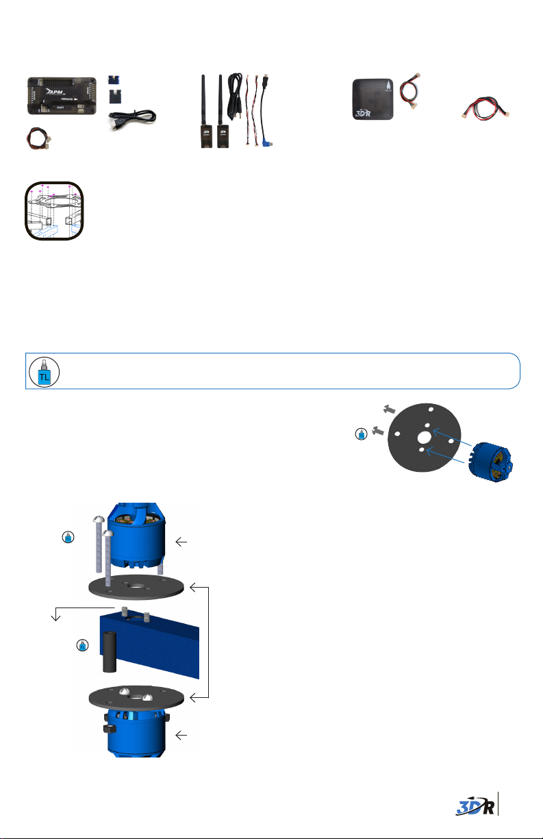
You may have opted to also receive:
3DR APM 2.6:
3DR APM 2.6
Telemetry adapter
cable
4 mm JP1
jumper connector
6 mm PPM
jumper connector
Micro USB cable
3DR Radio:
Radios (2)
Antennas (2)
Micro-USB cable
Android OTG cable
Autopilot connectors
3DR uBlox GPS+Compass:
6-position to
5-position GPS
cable
3DR uBlox GPS
board with compass
4-position compass
cable
FRAME ASSEMBLY
1 Attach motors to arms
Each arm of your Y6 will have a top motor and a bottom motor attached to the arm using
co-axial motor mounting plates. To ensure motors are securely bolted to arms, apply a small
amount of threadlock to each bolt before fastening.
Threadlocking compound is an important component to ensure your motors remain
firmly attached! For application tips, check out this video: goo.gl/bM3MA.
Attach mounting plates to bottom motors:
Using two 6 mm steel bolts and one co-axial motor
mounting plate, fasten motor onto plate as shown.
Repeat for three of six motors.
Secure with
6 mm bolts
Attach
motor
here
25 mm
bolts
6 mm bolts
19 mm hollow
spacers
Top and bottom motors attached to
arm with mounting plates
Top motor
Mounting
plates
Bottom
motor
Bottom motor assembly
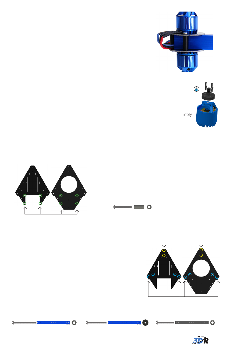
Attach top motors to arms:
Insert mounting plate between top motor and
arm. Make sure motor cables protrude in the
direction of the end of the arm.
Fasten motor and plate to arm using two 6 mm
steel bolts by accessing through the two large
holes in the bottom of the arm. Repeat for all
three arms.
Secure mounting plates together:
Place mounting plates with bottom motors
attached on underside of arm so that the three
outer holes in the plates align. Insert a 19 mm
hollow spacer between top and bottom holes;
thread a 25 mm bolt through spacer and plates.
Secure with a metal nut. Repeat for all three
holes on mounting plates. Repeat for all three
arms.
2
Thread motor cables through arms:
Thread the cables from the top motors through
the ends of the arms. You’ll want to distinguish
between top and bottom motor cables, so use a
pen or piece of tape to mark the protruding ends of
the top motor cables before threading the bottom
motor cables through the arms.
Completed motor assembly
Install motor collets2
Attach a threaded collet to the top of each motor using the
four small screws included with collets. Apply threadlock to
each screw before fastening. Repeat for all six motors.
Motor collet assembly
3 Attach top and bottom plates to arms
The top and bottom plates will form the main frame of your copter. We’ll attach these plates
both to each other and to your copter’s arms.
Top plateBottom plate
Attach top and bottom plates together through the
four aligning holes near the front ends of the plates as
shown using a 25 mm bolt, 19 mm hollow spacer, and
metal nut.
25 mm bolt + 19 mm spacer + metal nut
Attach at four points
Next attach the arms to the plates. The black arm will
attach to the narrowest angle of the triangular plates.
The two blue arms indicate your copter’s front-facing
Attach black arm here
direction and will attach to either side of the front of the
plates.
Place the arm between the two plates so the two holes
in the arm align with the holes in the plates. Insert a bolt
into each hole from under the bottom plate and secure
with nuts above the top plate. For inner holes use 35 mm
bolts and metal nuts; for outer holes on blue arms use 30
mm bolts and thumb nuts; for the outer hole on the black
arm use a 25 mm bolt and metal nut. Insert bolts from
below the bottom plate so that nuts are attached above
Attach blue arms here
the top plate.
Inner holes use: Outer hole (black arm) use:
35 mm bolt + arm + metal nut
Outer holes (blue arms) use:
30 mm bolt + arm + thumb nut
25 mm bolt + arm + metal nut
3
 Loading...