


DIY QUAD
Build Manual
V.A
2014
1

Contents
Thanks for purchasing a DIY Quad!
These instructions will show you how to assemble a Quad using the Pixhawk autopilot system and ArduCopter/APM:Copter firmware. If you plan to use other components in your build, please adjust these instructions accordingly. For online instructions, visit 3dr.com/diy-quad-kit.
Frame parts |
3 |
|
Electronics |
4 |
|
Tools |
4 |
|
1 |
Motor assembly |
5 |
2 |
Power system wiring |
8 |
3 |
Body plate assembly |
10 |
4 |
Pixhawk assembly |
15 |
5 |
Leg assembly |
21 |
6 |
Calibration |
22 |
7 |
Propeller assembly |
22 |
2
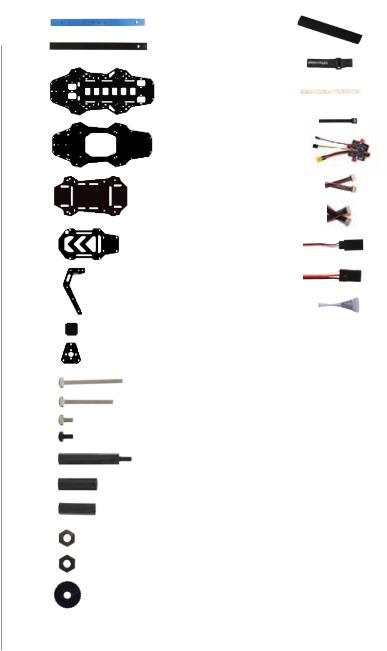
Frame parts
blue arms (2)
black arms (2)
base plate
top plate
Pixhawk plate
accessory plate
leg plates (8)
leg support plates (4)
motor plates (8)
30 mm bolts (6)
25 mm bolts (30)
5 mm bolts (32) nylon bolts (4)
30 mm male-female stando s (4)
19 mm hollow spacers (20)
18 mm female-female stando s (12)
metal nuts (42)
nylon nuts (4)
thumb nuts (2)
velcro strips (one pair)
velcro straps (3)
dual lock zip ties
power distribution board
15 cm four-wire cable
15 cm six-wire cable
15 cm female-female servo cable
30 cm male-female servo cable
threadlocker
3
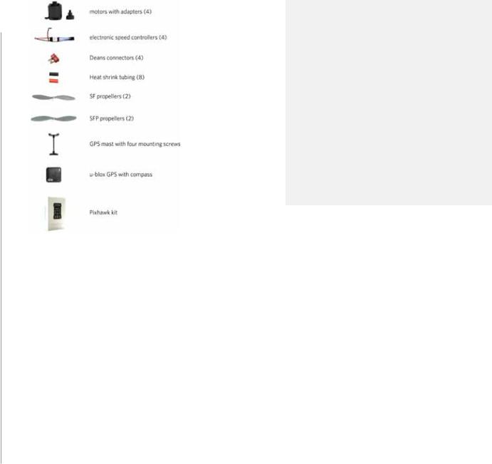
Electronics
Tools
This build uses the Pixhawk autopilot system, including these components:
• Pixhawk autopilot
• u-blox GPS with Compass
• Telemetry radios
• Radio control system
• ArduCopter/APM:Copter firmware
Click here for more information about these components and to view compatible radio control systems.
To complete this build, you will need the following tools not included with your kit:
•Phillips screwdriver
•Double-side foam tape or other mounting adhesive
•Soldering equipment
Note: The electronics for this build require soldering. If you’re unfamiliar with soldering, our friends at Sparkfun have some great tutorials that can get you started, including this comic. For an example of exactly what soldering you’ll be doing in this build, view this video tutorial.
4

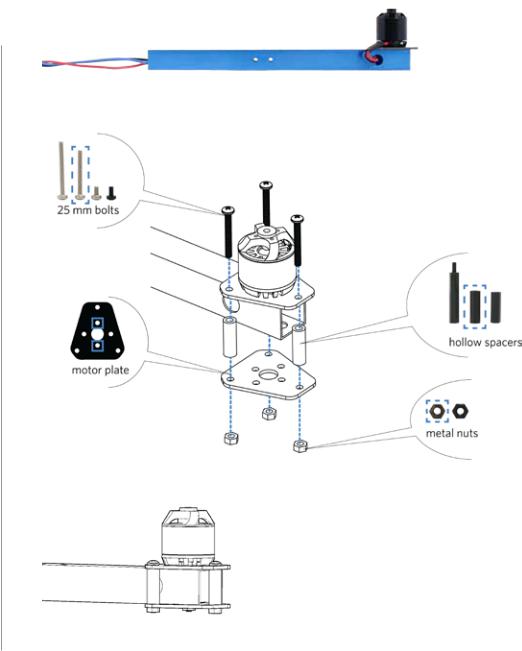
1 Motor assembly
Follow these instructions to assemble one motor.
1 Attach motor to arm
Place a motor plate on top of the arm with the short end of the plate facing towards the end of the arm. Place the motor on top of the plate, and align the two small holes in the motor, plate, and arm. Orient the motor with the cables as close as possible to the hole in the side of the arm.
Apply threadlocker to two 5 mm bolts, and secure the motor and plate to the arm from below by accessing through the two large holes in the bottom of the arm. When applying threadlocker, use less than one drop, and cover only four or five threads where the bolt connects with the motor. Make sure to insert the bolts into the holes in the bottom of the motor and not into the slots where they could interfere with the motor.
5
2 Thread motor cables through arm
Thread the motor cables through the hole in the side of the arm.
3 Attach bottom plate to arm
Place a motor plate against the bottom of the arm with the short end of the plate facing towards the end of the arm. Apply threadlocker to the ends of three 25 mm bolts (less than one drop covering four or five threads at the end of the bolt). Place a 19 mm hollow spacer between each of the pairs of holes in the two motor plates. Place the bolt through the motor plates and spacer, and secure from below with a metal nut.
Repeat these instructions for all motors.
6
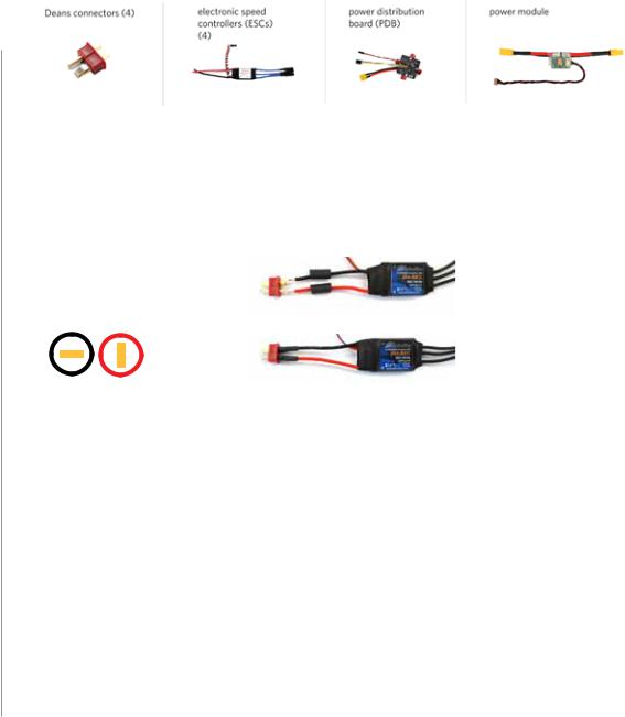
2 Power system wiring
Follow these instructions to connect the power system.
1 Solder Deans to ESCs
Solder a Deans connector to the red and black wires on each electronic speed controller (ESC). Check the Deans connectors for the + and – markings, and solder the + side to the red wire and the – side to the black wire. Don’t forget to add heat shrink tubing to the wires before soldering, and shrink the tubing over the finished connections.
2 Number ESCs
Use tape (or other method) to label each ESC with a number one through four.
Deans to ESC: negative = black positive = red
- +
7
 Loading...