


Aero-M
Operation Manual
Thank you for purchasing an Aero-M! This manual contains important information about your aerial mapping platform. Please read these instructions before your first flight.
1 |
Plan |
1 |
2 |
Fly |
20 |
3 Process |
37 |
|
Appendix |
41 |
|
Online information portal: |
3DR.com/Aero-M |
3DR support: |
help@3DR.com |
Terms and conditions: |
3DR.com/terms |
Pix4D instructions: |
support.Pix4D.com |
V.1 2014 ©3D Robotics DCT0010
1 Plan
Parts |
2 |
Flight Battery |
3 |
Charging |
3 |
Safety |
3 |
Powering the Aero |
4 |
Camera Setup |
5 |
3DR EAI |
5 |
Charging |
5 |
Starting a Mission |
5 |
Mounting |
6 |
Ground Station Setup |
7 |
Download Software |
7 |
Connect to Radio |
7 |
Mission Planning |
8 |
Operating Parameters |
8 |
Load Maps |
9 |
Draw Polygon |
10 |
Configure Survey |
11 |
Save and Write Mission |
19 |
1
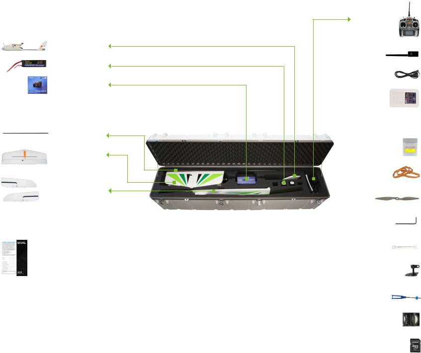
Parts
Aero
batteries (2)
camera
wing spar
horizontal stabilizer
wings
registration card and Pix4D license key
FPV/OSD System
If you selected to receive a FPV/OSD system, those components will be included with the Aero’s accessories. See page 34 for parts and instructions.
RC controller and accessories
ground station radio
micro-USB cable
charger and accessories
battery guard bag
wing rubber bands (4 plus 2 spare)
propellers (1 plus 1 spare)
hex keys (?)
propeller wrench
spare control horns
(2)
spare servo rods (2)
spare camera mount filters (2)
Pixhawk micro-SD card adapter
2
Flight Battery
The Aero is powered by a rechargeable lithium polymer (LiPo) battery.
Charge the battery before your first flight.
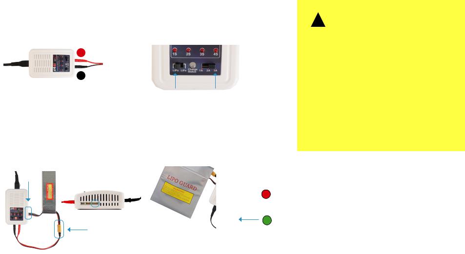
Charging
1 |
2 |
Connect the charger to the power adapter cable |
Set the charger to LiPo and 3A. |
and a wall outlet. Connect the red cable to the + |
|
port and the black cable to the - port. |
|
+
–
Charger with power cable and LiPo 3A split-wire charging cable
Charger settings
3 |
4 |
Connect the white connector to the 4S port, and |
Secure the battery inside the guard bag, |
join the two yellow connectors together. |
and charge until the status indicator |
|
displays green. |
Safety
!
Flying with a low battery is a safety risk and can render the battery permanently unusable. Always fly with a fully charged battery.
Charge the battery using a designated LiPo balance charger only. Always monitor the battery while charging. Protect the battery from extreme heat, extreme cold, puncturing, and flammable surfaces. Always transport, charge, and store the battery in the guard bag.
Inspect the battery for damage before and after flying. If you observe any swelling of the package or the battery ceases to function, do not use the battery; locate your local battery recycling center, and dispose of the battery. In the US and Canada, visit call2recycle.org to find a location. Do not dispose of the battery in the trash.
Charging
4S
Complete
Flight battery charging wiring |
Charging in process |
3
Powering the Aero
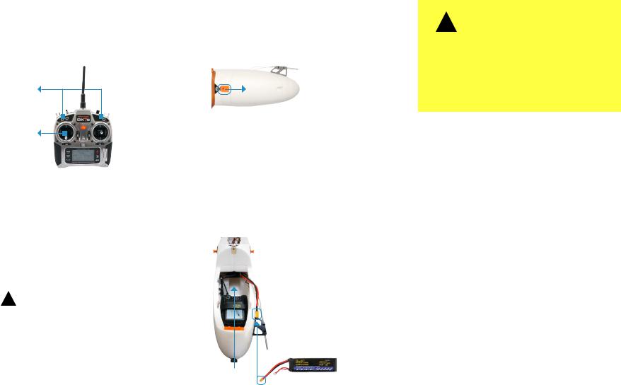
1
Turn on the controller. To avoid triggering the controller’s startup alarm, ensure that all switches are set back (away from you) and the throttle stick is set fully down.
Switches
Throttle stick
RC controller
3
Insert a charged battery into the battery slot, and attach the yellow connectors. This will power on the Aero.
!
Hold the Aero still and level while it powers on.
Attach the velcro above the battery slot to the velcro on the battery. Close and secure the lid onto the battery compartment.
2
Open the battery compartment by sliding the knob on the orange switch forward and lifting out the lid.
Aero: battery compartment lid
battery connector
battery slot
flight battery
Aero: battery compartment interior
!
It is important to establish communication before powering on the Aero. Always turn on the controller before connecting the battery. When powering off the Aero, disconnect the battery before turning off the controller.
4
Camera Setup
The Aero includes a Canon PowerShot SX260 HS running the 3DR EAI script.
3DR EAI (Exposure-Aperture-ISO)
3DR EAI runs on the Canon Hacker Development Kit (CHDK), a powerful opensource tool that expands the functionality of Canon point-and-shoot cameras. 3DR EAI optimizes image exposure and integrates with the Pixhawk autopilot to enable distance-based imaging.
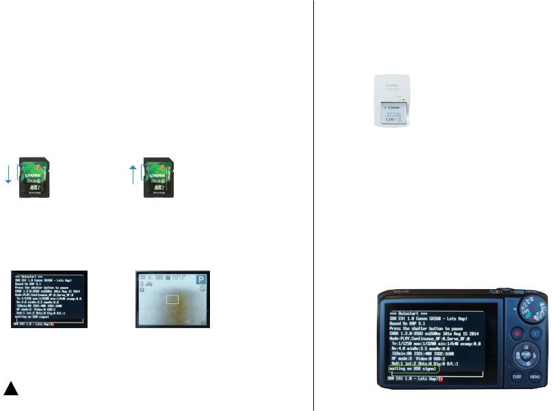
This software is designed to load off the camera’s SD card, leaving the original Canon programming intact. The yellow switch on the side of the SD card allows you to lock or unlock the card. Lock the SD card to run 3DR EAI; unlock the SD card to save images to your ground station or to boot the camera with its original programming.
For more information about 3DR EAI, see page 43.
SD card locked |
SD card unlocked |
Load 3DR EAI |
Load default Canon software |
»» Fly a mapping mission |
»» View images on camera |
|
»» Save images to ground station |
|
»» Update script |
Camera running 3DR EAI |
Camera running Canon software |
!Power off the camera before removing the SD card.
Charging
Charge the camera battery before your first flight. Once fully charged, insert the battery into the camera.
 status indicator
Canon battery charger
Starting a Mission
To prepare the camera to fly a mapping mission, ensure that the mode dial is set to P (program) mode. Power on the camera using the silver button on the top. 3DR EAI will start automatically, and you will see the script messages on the camera display. Check to see that the last line of the script reads waiting on USB signal. The camera is now ready to map!

 power button

 mode dial
Camera ready to map: waiting on USB signal
5
Mounting
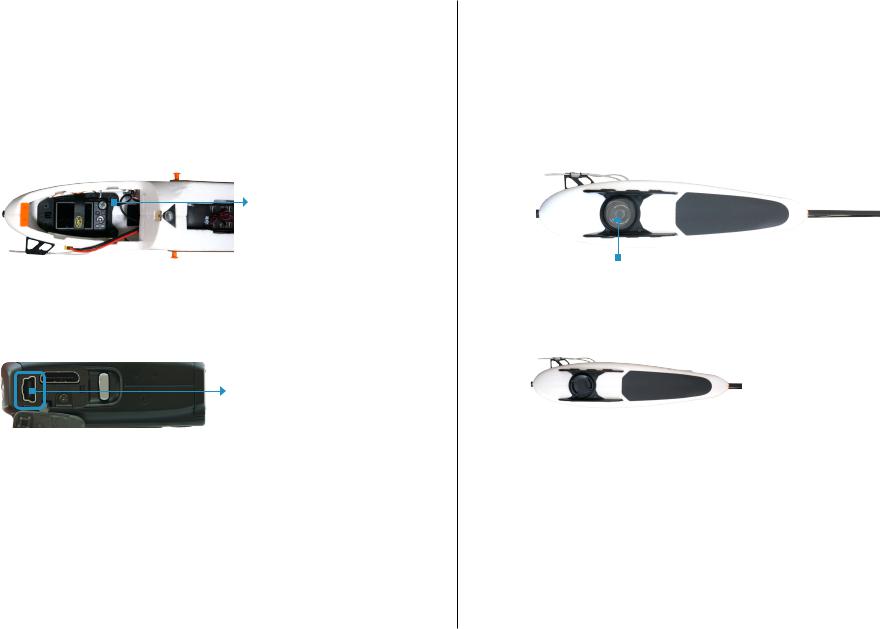
The camera mounts to the Aero inside the battery compartment and connects to the autopilot using the mini-USB cable. When the camera is ready to start the mission, insert the camera into the mount inside the battery compartment as shown below, connect the mini-USB cable to the camera, and secure the camera in place using the velcro strap.
autopilot integration cable
Aero battery compartment: camera mount
Connect mini-USB cable inside battery compartment here.
Camera (side)
The camera mount is fixed to the inside of the battery compartment and is not intended to be removed from the Aero.
The camera mount includes a lens cap that protects the filter during travel. Make sure to remove this lens cap before you fly, and check that the filter contains no foam particles, dirt, or scratches that could affect image quality.
It is expected that the filter will accumulate scratches after significant use. If you notice any damage to the filter that could affect image quality, unscrew the filter and replace with one of the extra filters provided with the Aero.
UV filter
Camera mount (bottom): cap removed
Camera mount (bottom): cap attached
6
Ground Station Setup
Mission Planner allows you to turn a Windows laptop into a full-featured ground station for configuring and monitoring autonomous missions. You will need to take this laptop into the field when you fly the mission. As part of the mission procedure, you will use the Pix4D Rapid Check to verify the quality of the image set before leaving the field.
Download Software
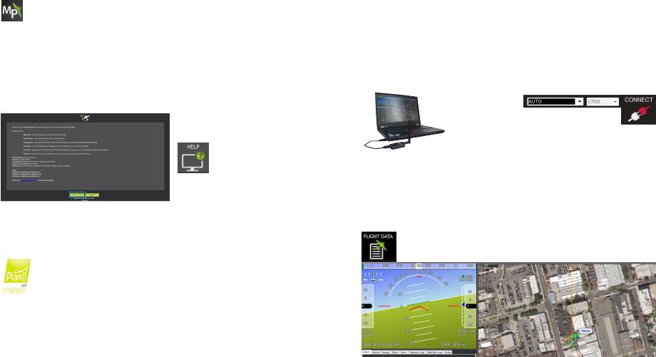
Mission Planner
Mission Planner is a full-featured ground station application for planning missions and monitoring the Aero in flight. Download Mission Planner from 3DR.com/download_software.
If you already have Mission Planner installed, make sure you’re running the most recent version: Select the Help tab and Check for Updates.
Mission Planner: Help tab
Pix4Dmapper LT 3DR Edition
Your license key for Pix4Dmapper can be found on the registration card inside the documents package.
Visit mapper.pix4d.com/license-redeem to create an account and redeem your license key; then visit pix4d.com/download to download Pix4Dmapper Discovery. Pix4D will automatically upgrade from the Discovery edition to the LT 3DR Edition (or Pro Edition if you selected to upgrade) when you log in to the program with your Pix4D account information.
Connect to Radio
To connect the Aero to Mission Planner, connect the ground station radio to the laptop, and power the Aero.
1 |
2 |
Connect the ground station radio to your |
Select 57600 and AUTO, then select CONNECT. |
laptop using the micro-USB cable. Open |
(When connecting directly to Pixhawk’s |
Mission Planner. |
micro-USB port, set the rate to 115200.) |
Mission Planner Connect tool (top-right corner))
Ground station laptop with radio connected
3
Select Flight Data to view live data from the Aero.
Mission Planner Flight Data tab: connected to aircraft
7
Mission Planning
Operating Parameters
The Aero is a complete solution for creating high-resolution visual-spectrum aerial maps.
|
Canon SX260 |
|
|
Pixhawk |
|
Pix4Dmapper |
|
autopilot |
3DR EAI |
||
LT 3DR Edition |
|||
system |
|||
|
|||
|
|
Mapping system diagram
To create a map, the Aero flies an autonomous mission over the survey site, using the integration between the Pixhawk autopilot and custom-programmed camera to capture images at a consistent distance interval. Pix4Dmapper then stitches these images together into a georeferenced, orthorectified mosaic.
The accuracy of the map depends on the configuration of the mission. Planning a mission that captures high-quality images requires balancing the Aero’s operating parameters with the environmental factors at the survey site.
Operating Parameters |
|
Camera |
Canon SX260 |
Camera Orientation |
Portrait (side facing forward) |
Operating Altitude |
80-120 m |
Standard Operating Altitude |
100 m |
Low-Wind Conditions |
0-6 m/s |
High-Wind Conditions |
7-10 m/s |
Maximum Wind Conditions |
10 m/s |
Operating Speed |
8-20 m/s |
Default Speed |
15 m/s |
Estimated Maximum Flight Time |
40 min |
Estimated Ground Resolution |
5 cm/pixel |
Estimated Maximum Survey Area |
1 km2 |
Minimum Photo Interval |
2 seconds |
8
Load Maps
Mission Planner allows you to plan the mission away from the mapping location; however, it is important to assess the environmental conditions on site at the time of the mission and adjust the flight plan if necessary. Alternatively, you can plan the entire mission at the mapping location. To create or alter the mission, Mission Planner requires an Internet connection to access the maps. If you’re unable to access the Internet on site, follow the instructions below to pre-fetch the maps within Mission Planner while you have Internet access.
1
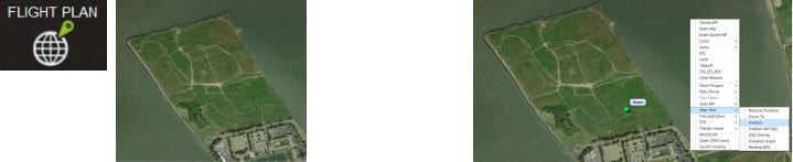
Open Mission Planner, select Flight Plan, and zoom to your flying location.
2
Right-click on the map, select Map Tool and Prefetch, and accept the defaults prompts. Mission Planner will download the maps for the selected location to your computer.
Mission Planner Flight Plan tab: zoom to mapping location |
Mission Planner Flight Plan tab: Select Prefetch |
3
Mission Planner will attempt to load the map data from the current level of zoom down to the closest level of zoom available. However, it can take hours to pre-fetch every level of zoom, and it is unlikely that the closer levels will be useful in planning the mission. To shortcut this process, check the slider on the right side of the map. The levels of zoom are represented by this slider from 0 (bottom) to 25 (top). Press the ESC key to skip levels of zoom at a greater detail than you need for mission planning.
9
Draw Polygon
To begin planning the mapping mission, select the area you want to map using the Polygon tool. You’ll be able to adjust the size and shape of the polygon later in the mission configuration process.
1 |
2 |
Select Flight Plan, and zoom to your |
Right click on the map. Select Draw Polygon and |
mapping location. |
Add Polygon Point. Click and drag to add points |
|
around the area you want to map. |
3
Right click on the polygon. Select Auto WP and Survey (Grid) to open the Survey Tool.
Mission Planner Flight Plan tab: zoom to mapping location
Mission Planner Flight Plan tab: open Survey tool
Mission Planner Flight Plan tab: draw polygon
!Units
The Survey Tool uses metric units. If your Mission Planner is set to imperial units, please change the settings to use metric to plan the mission. Support for imperial units in Mission Planner is coming soon; check 3DR.com/Aero-M for updates.
10

Configure Survey: Set Default Parameters
The Survey tool allows you to configure a mapping mission according to the Aero’s operating parameters and the current environmental conditions at the mapping location. First, set the default values for the Aero.
Mission Planner Survey tool
Set Camera
Canon SX260-SX280
Set Camera Orientation Uncheck the option for Camera top facing forward.
Set Default Speed 15 m/s
Apply Survey Speed
Check the option for Use speed for this mission. If unchecked, the mission will use the Aero’s default speed of 15 m/s regardless of the speed selected in the Survey Tool.
11
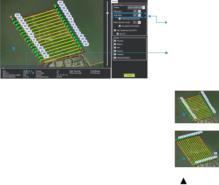
Configure Survey: Set Angle
Next configure the angle of the flight path for the current wind conditions.
wind
Mission Planner Survey tool
Mission Planner Tip: Adjust Polygon
Click and drag the red polygon points to adjust the size and shape of the polygon from the Survey Tool.
Set Angle
Wind Direction
In environments with winds of less than 6 m/s, set the angle so that the Aero flies into the wind. In winds from 7-10 m/s, configure the flight path to travel perpendicular to the wind so the Aero flies crosswind.
No. of Strips
Adjust the angle so that the Aero makes as few turns as possible to complete its course. The No. of Strips parameter shows how many passes the plane will make as you adjust the angle.
Review Wind Conditions On-Site
Always assess the wind conditions at your survey site at the time of the mission and adjust the mission accordingly.
Configure the flight path parallel with the wind in low winds (1-6 m/s).
wind
|
Configure the flight path perpendicular to the |
|
|
wind |
wind in high winds (7-10 m/s). |
|
|
|
|
|
|
|
|
|
|
! |
Use caution when flying in winds over 10m/s. Mapping results |
|
|
may degrade as a result of inability to make headway or maintain |
|
|
|
|
|
|
|
|
appropriate groundspeed. |
|
12 |
|
|
|
|
|
|
|
|
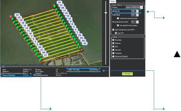
Configure Survey: Set Altitude
The survey altitude determines the duration of the mission and the ground resolution of the final map. Adjust altitude to balance flight time and power consumption with the current environmental conditions.
Mission Planner Survey tool
Check Ground Resolution
Ground Resolution is the centimeters per pixel that you will have in the map and corresponds to the amount of detail that you will see.
To improve ground resolution by decreasing the number of centimeters per pixel, decrease altitude.
Set Altitude
Standard operating altitude: 100 m
Operating altitude range: 80-120 m
Increasing altitude decreases flight time, allowing you to cover more area per minute. Decreasing altitude improves ground resolution. Set the altitude to get the best ground resolution while keeping the flight time under 40 min and the altitude under 120 m.
!
Keep altitude below 120 m, and ensure that the altitude is appropriate for your flying area and local regulations.
Check Flight Time
Flight Time estimates the duration of the mission. The total estimated flight time must be under 40 min for a fully charged Aero battery. To decrease flight time, increase altitude or speed.
High winds, humidity, high altitude, and extreme heat can affect power consumption and reduce flight time. Consider the environmental factors at your site when configuring flight time.
13
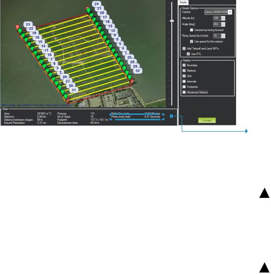
Configure Survey: Check Photo Interval
With the basic parameters in place, verify that the photo interval calculated from the altitude and speed complies with the operating parameters for the camera.
Mission Planner Survey tool
Check Photo Interval
Photo Every must be longer than 2 seconds for the SX260 camera.
Altitude
Increasing altitude increases photo interval.
!
Keep altitude below 120 m, and ensure that the altitude is appropriate for your flying area and local regulations.
Speed
Decreasing speed increases photo interval.
!
Ensure that the Use speed for this mission option is checked.
14
 Loading...