


3DR Plane
INSTRUCTIONS
Thank you for purchasing a 3DR Plane!
CONTENTS |
1 |
Fuselage |
|
|
|||
1 |
2 |
Right wing |
|
3 |
Left wing |
||
|
4 |
Horizontal stabilizer |
|
|
5 |
Vertical stabilizer |
|
2 |
|
6 |
Carbon fiber bar |
|
|
6 |
|
|
|
5 |
|
3 |
|
4 |
|
|
|
||
|
|
|
|
1 2
3
9
10 11
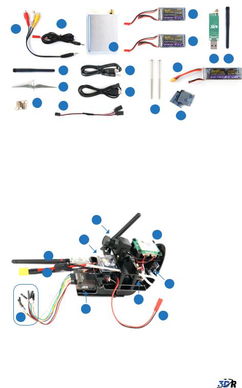
1Audio/video (AV) cable
2AV receiver power cable
3AV receiver antenna
4AV receiver
5AV transmitter battery (air)
6AV receiver battery (ground)
7Telemetry module (ground)
8Telemetry antenna (ground)
|
|
5 |
|
4 |
|
6 |
|
|
|
|
|
|
|
7 |
8 |
|
13 |
15 |
|
|
|
|
12
14
16
9Propeller
10Servo horn screws
11Ailerons Y cable
12Micro-USB cable
13USB extension cable
14Wing screws
15Main battery
16Adhesive Velcro squares
4
|
|
3 |
5 |
|
|
|
|
|
1 |
|
|
|
2 |
|
|
|
|
|
6 |
|
|
9 |
8 |
|
10 |
7 |
|
|
|
||
1 |
Telemetry (air) |
6 |
Air speed sensor |
2 |
Power module |
7 |
AV transmitter power connector |
3 |
AV transmitter |
8 |
On-screen display board |
4 |
Camera |
9 |
APM |
5 |
GPS module |
10 Input connectors |
|

Bixler Assembly Manual
Please refer to the assembly manual included with your plane to install main wings, stabilizers, and other parts of the plane’s frame. Use the Y-cable to connect the aileron cables from the left and right wings.
WIRING APM OUTPUTS
Connect the servo and electronic speed controller (ESC) wires to APM’s outputs pins in the order indicated below. Connect the white wire to the S pin (top row), the red wire to the + pin (center row), and the black wire to the - pin (bottom row).
Servo cables are labelled by type. Connect them to APM’s output pins as shown.
Rudder
Throttle
Elevator
Ailerons
CONNECT RC RECEIVER
|
Connect the wires from the APM inputs to |
|
the signal pins on your RC receiver. The |
|
wires are labeled with the channel they |
|
should connect to. |
|
Connect the black wire to a ground pin on |
APM inputs wires |
the receiver, and connect the red wire to a |
power (five volts) pin on the receiver. |
Connect inputs wires to RC receiver
 Loading...