

Page 1

EtherLink® XL PCI 1 0 Mbps
Network Interface Cards
User Guide
Member of the 3Com EtherLink XL family of
network interface cards
http://www.3com.com/
Part No. 09-1139-001
Published June 1998
Page 2

3Com Corporation ■ 5400 Bayfront Plaza ■ Santa Clara, California ■ 95052-8145
Copyright © 1998, 3Com Corporation. All rights reserved. No part of this documentation may be
reproduced in any form or by any means or used to make any derivative work (such as translation,
transformation, or adaptation) without written permission from 3Com Corporation.
3Com Corporation reserves the right to revise this documentation and to make changes in content
from time to time without obligation on the part of 3Com Corporation to provide notification of such
revision or change.
3Com Corporation provides this documentation without warranty, term, or condition of any kind,
either implied or expressed, including, but not limited to, the implied warranties, terms or conditions
of merchantability, satisfactory quality, and fitness for a particular purpose. 3Com may make
improvements or changes in the product(s) and/or the program(s) described in this documentation
at any time.
If there is any software on removable media described in this documentation, it is furnished under a
license agreement included with the product as a separate document, in the hard copy documentation,
or on the removable media in a directory file named LICENSE.TXT or !LICENSE.TXT. If you are unable to
locate a copy, please contact 3Com and a copy will be provided to you.
UNITED STATES GOVERNMENT LEGEND
If you are a United States government agency, then this documentation and the software described
herein are provided to you subject to the following:
All technical data and computer software are commercial in nature and developed solely at private
expense. Software is delivered as “Commercial Computer Software” as defined in DFARS 252.227-7014
(June 1995) or as a “commercial item” as defined in FAR 2.101(a) and as such is provided with only such
rights as are provided in 3Com’s standard commercial license for the Software. Technical data is pr ovided
with limited rights only as provided in DFAR 252.227-7015 (Nov 1995) or FAR 52.227-14 (June 1987),
whichever is applicable. You agr ee not to remove or deface any portion of any legend provided on any
licensed program or documentation contained in, or delivered to you in conjunction with, this User Guide.
Unless otherwise indicated, 3Com registered trademarks are registered in the United States and may or
may not be registered in other countries.
3Com, the 3Com logo, Dynamic
trademarks of 3Com Corporation. AutoLink and PACE are trademarks of 3Com Corporation.
3ComFacts is a service mark of 3Com Corporation.
Anixter is a trademark of Anixter Bros., Inc. Artisoft and LANtastic are trademarks of Artisoft, Inc.
Banyan and VINES are trademarks of Banyan Systems, Incorporated. CompuServe is a registered
trademark of CompuServe, Inc. Alpha, DEC, and PATHWORKS are trademarks of Digital Equipment
Corporation. OS/2 is a trademark of International Business Machines Corporation. Microsoft,
Windows, and Windows NT are trademarks of Microsoft Corp. Novell and NetWare are trademarks
of Novell, Inc. SCO is a trademark of The Santa Cruz Operation, Inc.
All other company and product names may be trademarks of the respective companies with which they
are associated.
Guide written by Nick Franks. Edited by Nancy Kurahashi. Illustrated by Mary Inden. Produced by
Georgi Felix.
Access
, EtherDisk, EtherLink, and SmartAgent are registered
ii
Page 3

ONTENTS
C
A
BOUT THIS GUIDE
Finding Specific Information in This Guide 1
Conventions 2
1
I
NSTALLING THE NETWORK INTERFACE CARD
Preparing for Installation 1-2
Inserting the NIC 1-3
Connecting to the Network 1-5
RJ-45 Port 1-5
BNC Port 1-6
AUI Port 1-7
Interpreting the Link LED 1-8
2
I
NSTALLING THE NETWORK DRIVER
Windows 95 2-1
Windows 95 Build 950 2-2
Windows 95 OSR2 2-4
Confirming Installation 2-6
Windows NT 2-6
Windows NT 4.0 2-7
Windows NT 3.51 2-8
Novell NetWare Client Driver 2-10
Running AutoLink Software 2-10
Novell NetWare Server Driver 2-11
NetWare 3.12 2-11
NetWare 4.10 and 4.11 2-12
Multiple NICs 2-12
Supported Network Drivers 2-14
3
T
ROUBLESHOOTING INSTALLATION PROBLEMS
Running Diagnostic Programs 3-1
iii
Page 4

3Com DOS Diagnostic Program 3-2
3Com NIC Diagnostics Program 3-2
Running NIC Tests 3-2
Running the Echo Test 3-4
3Com Support Services 3-7
Accessing the Help System 3-8
Release Notes, Frequently Asked Questions,
and KnowledgeBase Topics 3-8
Removing NIC Software 3-9
Windows 95 and Windows NT 4.0 3-9
Windows NT 3.51 3-9
Frequently Asked Questions 3-10
4
C
HANGING CONFIGURATION SETTINGS
Using the DOS Configuration Program 4-2
Running the 3Com NIC Diagnostics Program 4-2
Displaying Configuration Settings 4-2
Changing Configuration Settings 4-4
Enabling PACE Support 4-5
A
S
PECIFICATIONS AND CABLING REQUIREMENTS
Specifications A-1
Cabling Requirements A-1
Twisted-Pair Cable A-2
10BASE-T Operation A-2
10BASE-T Specifications A-3
RJ-45 Connector Pin Assignments A-3
B
C
ONFIGURING ADVANCED
Operational Settings B-1
FIFO Packet Threshold B-1
Concurrent UDP Streams B-1
Low-Priority Ratio B-2
Natural Packet Interval B-2
Option Descriptions B-2
Disable Switch Packet Prioritization B-2
Disable Receive Packet Buffering B-3
Changing Operational Settings B-3
iv
PACE O
PTIONS
Page 5

Changing Ranges and Protocols B-4
C
T
ROUBLESHOOTING NETWORK CONNECTION PROBLEMS
Eliminating Potential Causes of Problems C-1
Troubleshooting Hubs with Crossover Cable C-2
D
T
ECHNICAL SUPPORT
Support from Your Network Supplier D-1
Online Technical Services D-1
World Wide Web Site D-2
3Com Bulletin Board Service D-2
Access by Analog Modem D-2
Access by Digital Modem D-3
3ComFacts Automated Fax Service D-3
I
NDEX
3COM C
FCC C
FCC D
ORPORATION LIMITED WARRANTY
LASS
B S
ECLARATION OF CONFORMITY
3COM END U
TATEMENT
SER SOFTWARE LICENSE AGREEMENT
v
Page 6

Page 7

IGURES
F
1-1
3C900B Network Interface Cards 1-1
1-2
Installing the 3C900B NIC 1-4
1-3
Connecting to the RJ-45 Port on the 3C900B NIC 1-5
1-4
Connecting to the BNC Port on the 3C900B-COMBO NIC 1-6
1-5
Connecting to the AUI Port on the 3C900B-COMBO NIC 1-7
2-1
Selected NIC Screen of the Configuration and
Diagnostic Program 2-13
3-1
3Com NIC Diagnostics General Screen 3-3
3-2
Diagnostics Screen 3-4
3-3
Echo Test Responder Screen 3-5
3-4
Echo Test Sender Screen 3-6
3-5
Echo Test Statistics Screen 3-6
3-6
3Com NIC Diagnostics Support Screen 3-7
4-1
3Com NIC Diagnostics General Screen 4-3
4-2
NIC Details Screen 4-3
4-3
3Com NIC Diagnostics Properties Screen 4-4
4-4
3Com DynamicAccess Setup Screen 4-5
A-1
RJ-45 Connector Pin Assignments A-3
B-1
Advanced PACE Options Screen B-3
C-1
Straight-through and Crossover Cable Pinouts C-2
vii
Page 8

ABLES
T
1
Notice Icons 2
2
Text Conventions 2
1-1
3C900B NIC Models 1-2
1-2
LED Interpretation 1-8
2-1
Network Driver Text File Names 2-14
3-1
Frequently Asked Questions 3-10
4-1
Option Settings 4-1
A-1
Unshielded Twisted-pair Cable Categories A-2
viii
Page 9

BOUT THIS
A
About This Guide provides an overview of this guide,
describes guide conventions, and tells you where to look
for specific information.
This guide describes how to install, configure, and
troubleshoot 3Com® EtherLink® XL PCI 10 Mbps (3C900B)
network interface cards (NICs).
If a release note is shipped with this product, and
the information in the release note differs from the
information in this guide, follow the instructions in the
release note.
This guide is for network administrators and users who are
familiar with PCs and Ethernet networks.
G
UIDE
Finding Specific Information in This Guide
This table shows the location of specific information in
this guide.
If you are looking for Turn to
NIC installation and cabling information Chapter 1
Network driver installation instructions Chapter 2
Information about troubleshooting installation problems Chapter 3
Information about changing NIC configuration settings Chapter 4
Specifications, cable requirements, and RJ-45 pin assignments Appendix A
Information about advanced PACE™ options Appendix B
Information about crossover cables and troubleshooting techniques Appendix C
Technical support Appendix D
Page 10

2 ABOUT THIS GUIDE
Conventions
Table 1 and Table 2 list conventions that are used
throughout this guide.
Table 1 Notice Icons
Icon Notice Type Description
Information note Important features or instructions
Caution Information to alert you to potential damage to a
Warning Information to alert you to potential personal injury
Table 2 Text Conventions
Convention Description
Screen displays This typeface represents information as it appears on
The words “enter”
and “type”
Keyboard key names If you must press two or more keys simultaneously, the
Menu commands
and buttons
Words in
italicized type
Words in
bold-face type
program, system, or device
the screen.
When you see the word “enter” in this guide, you must
type something, and then press the Return or Enter key.
Do not press the Return or Enter key when an instruction
simply says “type.”
key names are linked with a plus sign (+). Example:
Press Ctrl+Alt+Del
Menu commands or button names appear in italics.
Example:
From the Help menu, select Contents.
Italics emphasize a point or denote new terms at the place
where they are defined in the text.
Bold text denotes key features.
Page 11
INSTALLING THE
1
NETWORK INTERFACE CARD
This chapter describes the 3Com® EtherLink® XL PCI
10 Mbps 3C900B network interface cards (NICs).
Procedures are provided for installing the NIC hardware
and software and connecting each version of the NIC
to an Ethernet network.
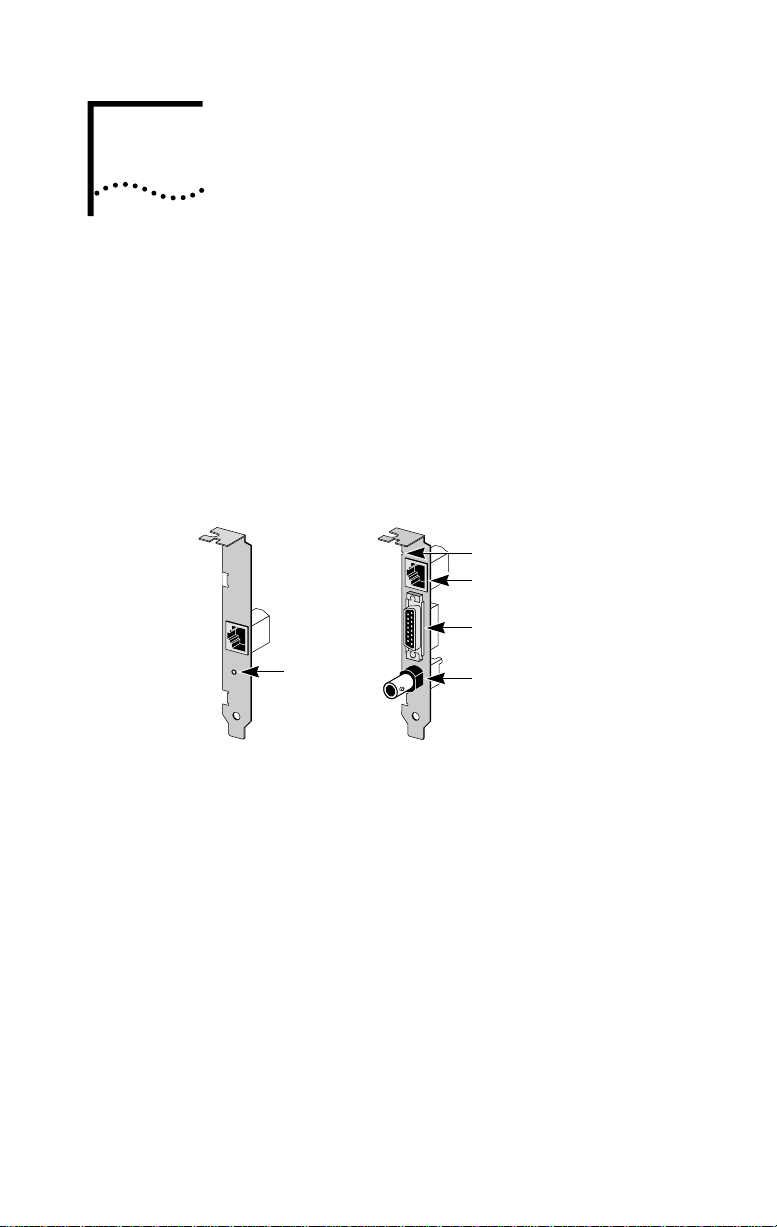
Figure 1-1 shows the two versions of the 3C900B NIC.
These NICs connect your PC to a 10 Mbps Ethernet
network using up to three different types of media.
LED
RJ-45 port
AUI port
LED
BNC port
3C900B-COMBO3C900B-TPO
Figure 1-1 3C900B Network Interface Cards
Table 1-1 shows the cable, connector, transceiver,
and maximum network segments for the various
3C900B NIC models.
Page 12

1-2 CHAPTER 1: INSTALLING THE NETWORK INTERFACE CARD
Table 1-1 3C900B NIC Models
NIC Model Cable Connector Transceiver
3C900B-TPO Category 3, 4,
or 5 unshielded
twisted-pair
(10BASE-T)
3C900B-COMBO Category 3, 4,
or 5 unshielded
twisted-pair
(10BASE-T)
10BASE5 thick
Ethernet coaxial
10BASE2 thin
Ethernet coaxial
RJ-45 On-board 328 ft/100 m
RJ-45 On-board 328 ft/100 m
15-pin AUI External 1640 ft/500 m
BNC On-board 1000 ft/305 m
Preparing for Installation
Before you install the 3C900B NIC, verify that you have all
of the components. If any of these items are damaged or
missing, contact your shipper or network supplier.
■ EtherLink XL PCI NIC (3C900B)
■ EtherLink XL PCI Network Interface Cards User Guide
(this guide)
■ 3Com 3C900B EtherDisk diskettes 1 and 2
You also need to know the following about your
network environment:
■ The kind of network cabling that is used to connect to
the network at your site. Y ou must use the same kind of
network cable. The NIC that you install in your PC must
have a port that matches the connector on the network
cable that you use.
■ Your network protocol (IPX, NetBEUI, or TCP/IP).
The next step is to install the NIC in the PC.
Maximum
Network
Segment
Page 13

Inserting the NIC
The following instructions apply to installing the 3C900B
NIC in most PCs. If these instructions are not appropriate
for your PC, refer to the documentation that accompanied
your PC.
CAUTION: Each NIC is packed in antistatic packaging to
protect it during shipment. Before handling the NIC, touch
the bare metal case of your PC. While you are handling the
NIC, wear a wrist strap grounded to the PC chassis.
Remove all jewelry from your hands and wrists and use
only insulated or nonconducting tools.
Follow these steps to install the NIC in your PC:
1 Turn the power off, and remove the power cord from
the PC.
2 Unscrew the cover screws and remove the cover.
On some PCs, it may be necessary to remove all cables
before the cover can be removed.
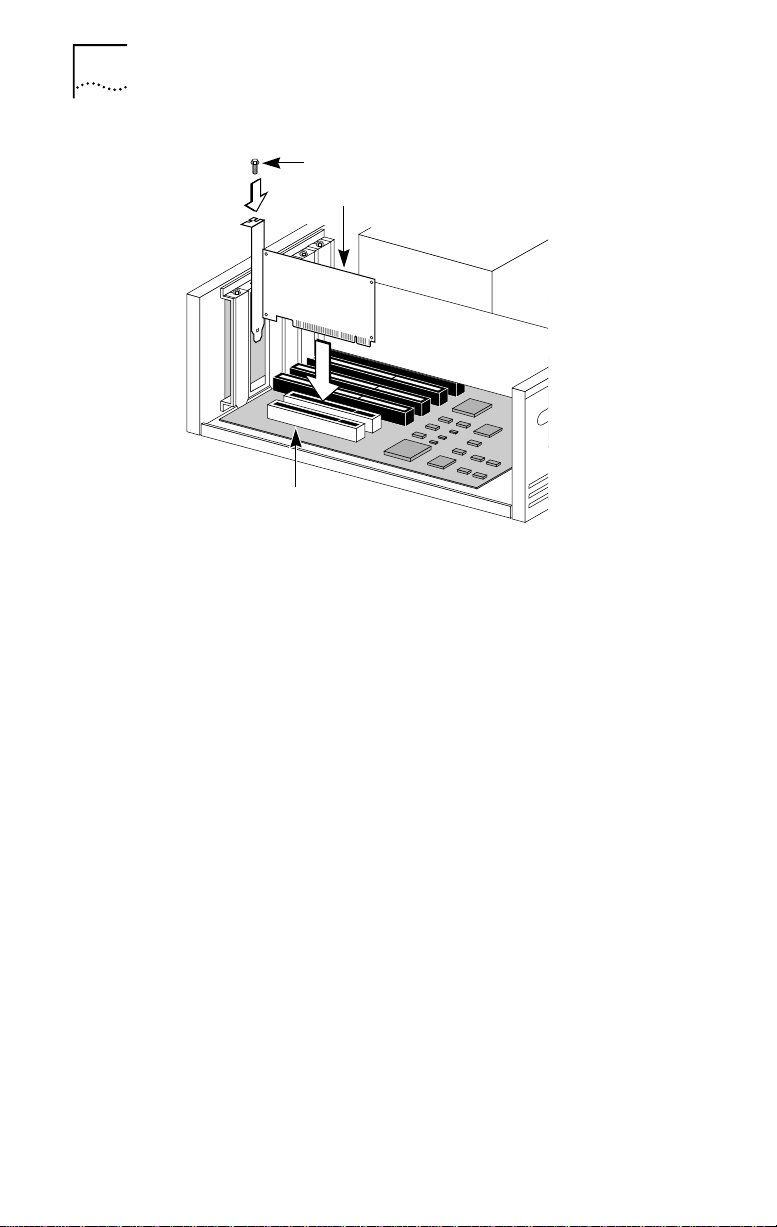
3 Locate an available bus-mastering PCI slot and
remove the screw from the corresponding backplate
(Figure 1-2). Save the screw.
Early PCI PCs that have more than one PCI slot typically have
only one bus-mastering PCI slot. In this case, the correct PCI
slot to use is usually the one closest to the power supply in
the PC. However , you should consult your PC documentation
to verify this. In newer PCI systems, all PCI slots are
bus-mastering slots.
Many PCs have both ISA and PCI slots. Make sure that
you install the NIC only in a bus-mastering PCI slot. See
Figure 1-2. PCI slots are usually white, and they are shorter
than ISA slots.
Inserting the NIC 1-3
Page 14
1-4 CHAPTER 1: INSTALLING THE NETWORK INTERFACE CARD
PCI slot
Backplate screw
3C900B NIC
Figure 1-2 Installing the 3C900B NIC
4 Remove and discard the backplate.
5 Ensure that the shape and length of the edge
connector on the NIC match the slot that you intend
to use (Figure 1-2).
6 Carefully insert the NIC into the slot. Press firmly with
steady pressure to ensure that the NIC is fully seated
in the slot.
When the NIC is correctly inserted in the slot, the NIC
backplate is flush with the PC backplane.
7 Secure the NIC with the backplate screw.
8 Replace the PC cover. Reinsert and tighten the
cover screws.
9 Reconnect all power and peripheral cables.
Page 15
Connecting to the Network
This section describes how to connect the 3C900B NIC
to an Ethernet network using an RJ-45, BNC, or AUI port.
Each 3C900B NIC provides different network ports, as
shown in Figure 1-1. Follow the procedure for the network
port on the NIC that you install.
When you first install the NIC and power on the PC, the
LED on the NIC backplate lights, but the link is not active.
To enable the link, you must load the network drivers. See
“Interpreting the Link LED” at the end of this chapter for
more information.
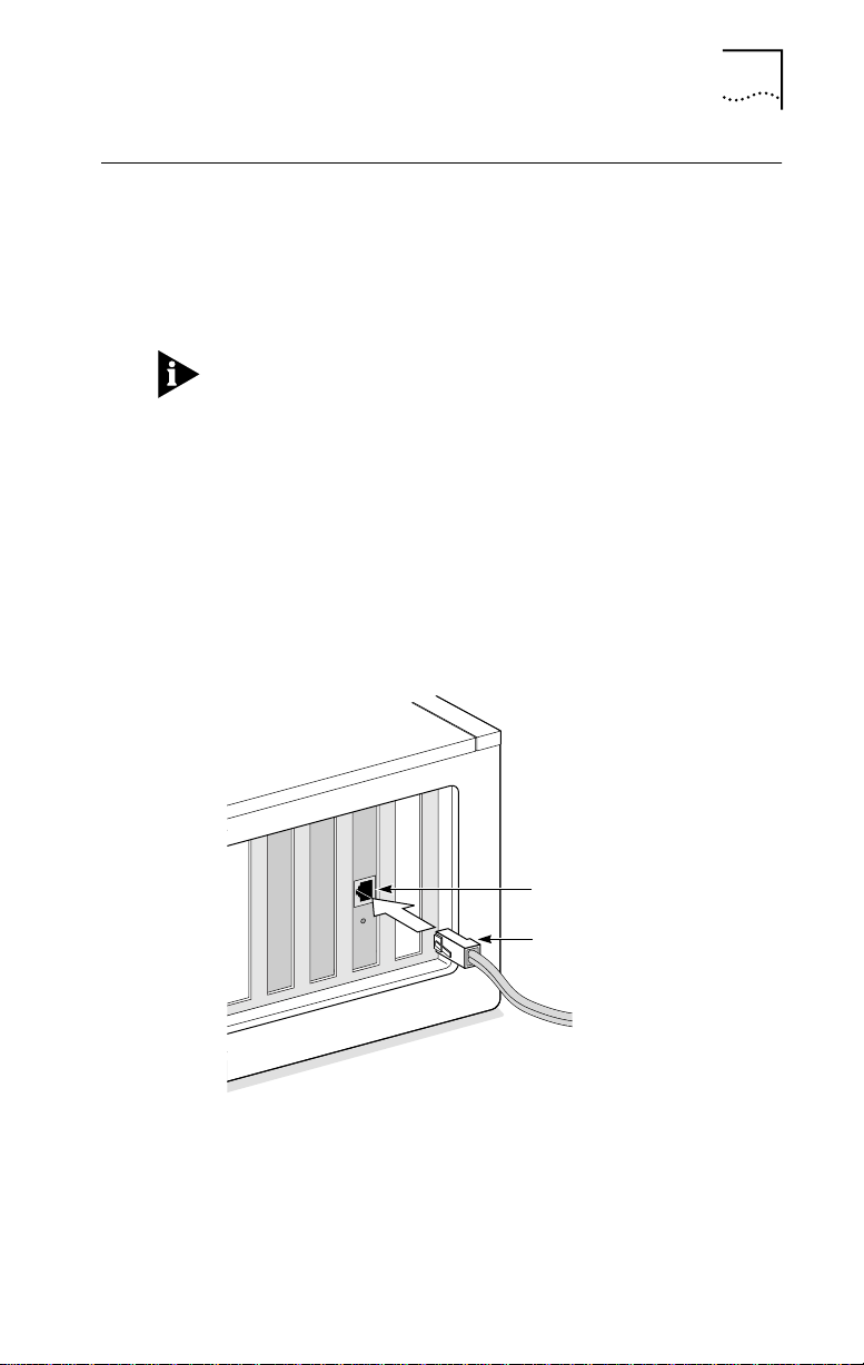
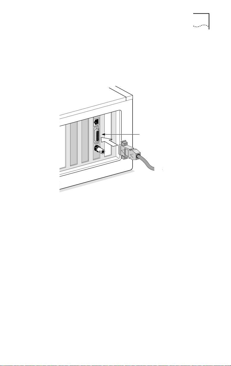
RJ-45 Port
Follow these steps to connect the RJ-45 port on the
3C900B-TPO and COMBO NICs to the network:
1 Plug the RJ-45 connector on the twisted-pair network
cable into the RJ-45 port on the NIC backplate. See
Figure 1-3.
Connecting to the Network 1-5
RJ-45 port
RJ-45
connector
Figure 1-3 Connecting to the RJ-45 Port on the 3C900B NIC
2 Connect the other end of the network cable to an
active network port.
Go to “Interpreting the Link LED” later in this chapter.
Page 16
1-6 CHAPTER 1: INSTALLING THE NETWORK INTERFACE CARD
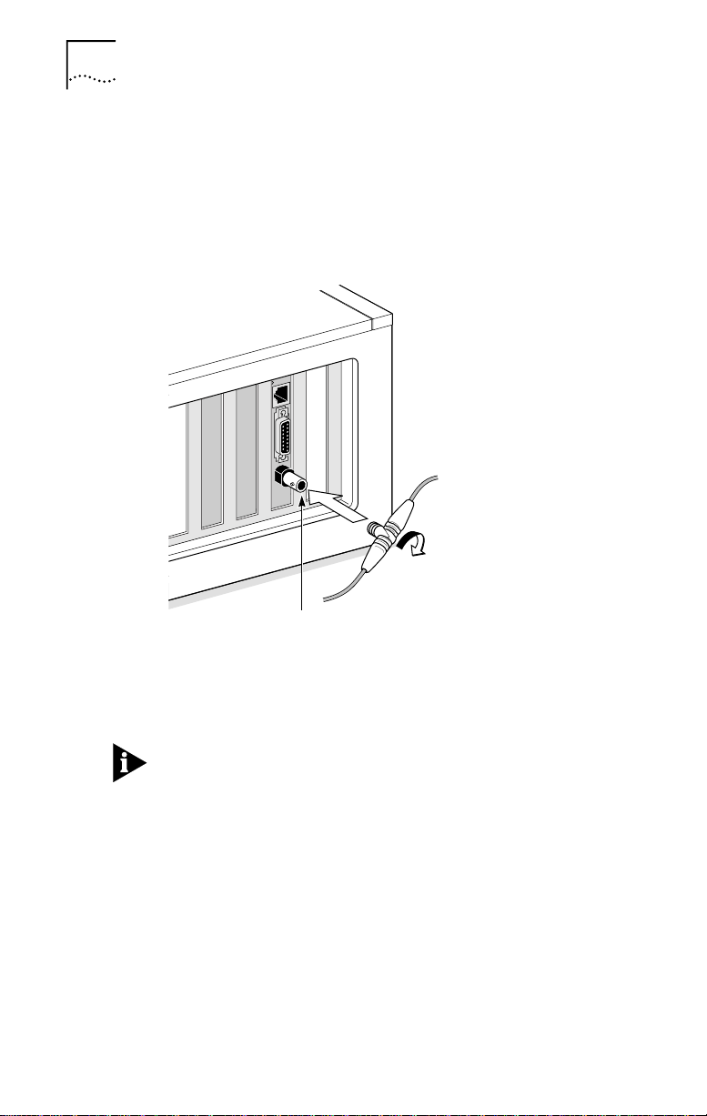
BNC Port
Follow these steps to connect the BNC port on the
COMBO NIC to the network:
1 Connect the BNC connector on the thin Ethernet
coaxial cable to the BNC port on the NIC. See
Figure 1-4.
BNC connector
BNC port
Figure 1-4 Connecting to the BNC Port on the 3C900B-COMBO NIC
2 Connect the other end of the network cable to
another PC or a 50-ohm terminator.
If your PC is the last physical device in the network daisy
chain, you must connect a 50-ohm terminator to the other
end of the BNC T-connector.
The next step is to install the network driver. Go to the
next chapter.
Page 17
AUI Port
Connecting to the Network 1-7
Follow these steps to connect the AUI port (Figure 1-5) on
the 3C900B COMBO NIC to the network:
1 Locate the 15-pin AUI port on the NIC and move the
slide latch down to the open position.
AUI port
AUI connector
Figure 1-5 Connecting to the AUI Port on the 3C900B-COMBO NIC
2 Connect the thick Ethernet coaxial cable to the AUI
port on the NIC.
This connector attaches in only one way. Orient the AUI
connector to match the AUI port on the NIC.
3 Move the slide latch up to the closed position to lock
the AUI connector in place.
4 Connect the other end of the network cable to an
external transceiver.
The next step is to install the network driver. Go to the
next chapter.
Page 18

1-8 CHAPTER 1: INSTALLING THE NETWORK INTERFACE CARD
Interpreting the Link LED
The 3C900B NICs have one light-emitting diode (LED).
When the LED is on (but before the driver is loaded), the
LED indicates that the NIC is receiving power.
Other than indicating that the NIC is receiving power, the
LED serves no other purpose for either an AUI or a BNC
media connection. Table 1-2 explains the LED states for
3C900B NICs.
Table 1-2 LED Interpretation
LED
State
On
Off
Blinking
Meaning RJ-45 AUI BNC
If drivers are installed, the
connection is active.
If drivers are not installed, the
NIC is receiving power.
Something is preventing the
connection between the NIC
and the hub.
The cable polarity is reversed.
Try a different network cable or
contact your MIS representative.
Yes N/A N/A
Yes Yes Yes
Yes N/A N/A
Yes N/A N/A
Connector
If the NIC LED indicates a problem, check the following:
1 Ensure that your network hub and the network cable
connecting to your 3C900B NIC comply with the
10BASE-T specifications.
2 Ensure that the hub is powered on.
You have completed the hardware installation.
The next step is to install the network driver. Go to the
next chapter.
Page 19

INSTALLING THE
2
This chapter describes how to install the network driver
that allows the 3C900B NIC to transmit and receive data
over an Ethernet network.
To obtain the latest shipping version of a network driver, go
to the 3Com World Wide Web site:
http://www.3com.com/
Before attempting to install a network driver, ask your
network administrator which driver to install.
Go to the appropriate section in this chapter for the
procedure describing how to install the driver for the
network used at your site.
Windows 95
This section describes how to install the 32-bit
protected-mode driver in a PC running Microsoft
Windows 95. This driver can be used in both Microsoft
and NetWare environments, and it supports dRMON and
PACE™ technology.
Do not use the AutoLink software to install the network
driver under Windows 95. To install the network driver
under Windows 95, you need the Windows 95 installation
files. These files may be on a CD or standard diskettes, or
they may have been copied to your hard disk when
Windows 95 was installed on your system.
The version of Windows 95 installed on your PC
determines which of the following driver installation
procedures to use.
NETWORK DRIVER
Page 20

2-2 CHAPTER 2: INSTALLING THE NETWORK DRIVER
Follow these steps to determine the Windows 95 version
installed on your PC:
1 Right-click the My Computer icon and click Properties.
The System Properties window is displayed.
2 Check the version number on the General screen,
under System:
■ If 4.00.950 is displayed, follow the procedure for
Windows 95 Build 950.
■ If 4.00.950B is displayed, follow the procedure for
Windows 95 OSR2.
Windows 95 Build 950
Follow these steps to install the network driver in a PC
running the Build 950 version of Windows 95:
1 Install the NIC, connect to the network, and turn the
power on.
Windows 95 detects the NIC and displays the
New Hardware Found dialog box, prompting you for
the driver you want to install for your new hardware.
2 Select Driver from disk provided by hardware
manufacturer, and then click OK.
The Install from Disk dialog box is displayed.
3 Insert EtherDisk diskette 2 in drive A and enter the
path to drive A if it is not already displayed.
4 Click OK.
■ If this is the first time that networking is being installed
on your PC, the Identification tab of the Network
window is displayed. Go to step 5.
■ If networking has already been installed, you are
prompted for the Windows 95 CD. In this case, go
to step 7.
5 In the specified fields of the Identification tab
screen, enter:
■ The name of your computer
Give your PC a unique name of up to 15 characters.
Spaces are not allowed; however, you can use hyphens.
Page 21

Windows 95 2-3
■ Your workgroup name
A workgroup (for example, your department name)
is composed of the PCs you usually communicate
with and the workgroup’s shared resources
(for example, printers).
If you use peer-group networking, the workgroup
name is your peer group. Peers can see each other
when they look in the Network Neighborhood.
For information on peer-to-peer networking, see
the W95NDIS.TXT file in the HELP directory on
EtherDisk diskette 1.
■ A description of your computer
Filling in this field is optional. The information that you
enter in this field is visible to others when they view
your computer on the network. The description should
help others to know the function or use of your PC.
6 Click Close.
Files are copied and you are prompted for the
Windows 95 CD.
7 Click OK.
The Copying Files dialog box is displayed.
8 Remove EtherDisk diskette 2 from drive A.
9 If not already displayed, enter the path to the
CD-ROM drive, insert the Windows 95 CD in the
CD-ROM drive, and click OK.
Files are copied, and you are then prompted to restart
your computer.
10 Click Yes.
Windows prompts you to enter your name and
network password.
11 Enter your user name and password, and then
click OK.
To confirm successful installation, go to “Confirming
Installation” later in this chapter.
Page 22

2-4 CHAPTER 2: INSTALLING THE NETWORK DRIVER
Windows 95 OSR2
Follow these steps to install the network driver in a PC
running the OSR2 version of Windows 95:
1 Install the NIC, connect to the network, and turn the
power on.
Windows 95 detects the NIC. The Update Device Driver
Wizard starts and prompts you for a diskette or CD.
2 Insert EtherDisk diskette 2 in drive A and click Next.
Windows finds the driver and asks if you want to use
this driver.
3 Click Finish.
The Insert Disk dialog box prompts you for
EtherDisk diskette 2.
4 Click OK.
The Copying Files dialog box is displayed.
5 If not already displayed, enter the path to drive A.
6 Click OK.
■ If this is the first time that networking is being installed
on your PC, the Identification tab of the Network
window is displayed. Go to step 7.
■ If networking has already been installed, you are
prompted for the Windows 95 CD. In this case, go
to step 9.
7 In the specified fields of the Identification tab
screen, enter:
■ The name of your computer
Give your PC a unique name of up to 15 characters.
Spaces are not allowed; however, you can use hyphens.
■ Your workgroup name
A workgroup (for example, your department name)
is composed of the PCs you usually communicate
with and the workgroup’s shared resources
(for example, printers).
Page 23

Windows 95 2-5
If you use peer-gr oup networking, the workgroup name
is your peer group. Peers can see each other when they
look in the Network Neighborhood.
For information on peer-to-peer networking, see
the W95NDIS.TXT file in the HELP directory on
EtherDisk diskette 1.
■ A description of your computer
Filling in this field is optional. The information that you
enter in this field is visible to others when they view
your computer on the network. The description should
help others to know the function or use of your PC.
8 Click Close.
Once the installation files are copied to your hard disk,
Windows prompts you for the Windows 95 CD.
9 Click OK.
10 Remove EtherDisk diskette 2 from drive A and
click OK.
The Copying Files dialog box is displayed.
11 If not already displayed, enter the path to the
CD-ROM drive, insert the Windows 95 CD in the
CD-ROM drive, and click OK.
Windows 95 prompts you to reboot.
12 Click Yes.
Windows prompts you for your user name and password.
13 Enter your user name and password, and then
click OK.
To confirm successful installation, go to the next section.
Page 24

2-6 CHAPTER 2: INSTALLING THE NETWORK DRIVER
Confirming Installation
Follow these steps to confirm that the NIC is installed and
functioning correctly:
1 Right-click the My Computer icon, click Properties,
and then click the Device Manager tab.
A list of devices appears, arranged by type.
2 Double-click Network adapters.
The name of the installed NIC appears:
3Com EtherLink XL xxx 10 Mb Ethernet NIC
(3C900B-xxx)
where xxx represents the NIC model installed in your PC,
for example, TPO.
If a yellow exclamation point (!) or a red X appears next to
the NIC name, go to “Frequently Asked Questions” in
Chapter 3 to troubleshoot the NIC.
3 Double-click the name of the NIC to display a
description of the NIC and its current status.
The message in the Device status panel confirms that the
3C900B NIC is working properly.
4 Click Cancel to close each dialog box. Then close the
Control Panel and My Computer windows.
You have successfully installed and configured the
3C900B NIC.
Windows NT
This section describes how to install the network driver in a
PC running Microsoft Windows NT 4.0 or 3.51.
Do not use the AutoLink software to install the network
driver under Windows NT.
If Windows networking is not installed on your PC, you
may also need the following information from your
network administrator:
■ Whether you are on a LAN or are connecting to one
■ The protocol used in the Microsoft Windows network
through a modem
(typically TCP/IP or NetBEUI)
Page 25

■ The name of the Windows NT server domain or
workgroup that you belong to
■ The IP address that you will use if your network does
not have a DHCP server (TCP/IP only)
Windows NT 4.0
Follow these steps to install the network driver in a PC
running Windows NT 4.0:
1 Install the NIC, connect to the network, and turn the
power on.
2 Double-click the My Computer icon, double-click the
Control Panel icon, and then double-click the
Network icon.
The Network window appears.
3 Click the Adapters tab.
If you are replacing a NIC that was previously installed,
follow these steps. Otherwise, go to step 4.
a Select the existing NIC (that is being replaced) in the
Installed Adapters group.
b Click Remove.
c Click Yes in the Warning dialog box.
d Reboot the PC and repeat step 2.
4 Click Add.
The Select Network Adapter dialog box appears.
5 Click Have Disk.
6 Insert EtherDisk diskette 2 in drive A, enter the path
to drive A if it is not already displayed, and click OK.
The OEM Option dialog box appears.
7 If not already selected, select 3Com Fast
EtherLink/EtherLink XL PCI Busmaster NIC, and
click OK.
Windows copies files, and then the Setup Message dialog
box confirms that 3Com dRMON SmartAgent® software
has been successfully installed.
Windows NT 2-7
Page 26

2-8 CHAPTER 2: INSTALLING THE NETWORK DRIVER
8 Click OK.
The 3Com NIC Diagnostics window appears, confirming
successful driver installation.
9 Click Close.
The Network window appears, displaying the name of the
installed NIC.
10 Click Close.
If you are prompted for network information, enter the
information supplied by your MIS department.
Windows prompts you to restart your computer.
11 Click Yes.
The driver installation is complete.
To confirm successful installation, double-click the Network
icon in the Control Panel. Click the Adapters tab. The
3C900B NIC should appear on the list. If it is not on the list,
see Chapter 3 for troubleshooting information.
Windows NT 3.51
Follow these steps to install the network driver in a PC
running Windows NT 3.51:
1 Install the NIC, connect to the network, and turn the
power on.
2 In the Main window of the Program Manager,
double-click the Control Panel icon and then
double-click the Network icon.
The Network Settings window appears.
If you are replacing a NIC that was previously installed,
follow these steps. Otherwise, go to step 3:
a Select the existing NIC in the Installed Adapters Cards
group.
b Click Remove.
c Click Yes in the confirmation window.
Page 27

Windows NT 2-9
d Click OK in the Network Settings window and then click
Restart Now.
e After rebooting, repeat step 2.
3 Click Add Adapter.
The Add Network Adapter window appears.
4 Click the down arrow to expand the list box, select
<Other> Requires disk from manufacturer, and then
click Continue.
The Select OEM Option dialog box appears with the name
of the NIC displayed and selected.
5 Click OK.
Windows copies files, and then the Setup Message dialog
box confirms that 3Com dRMON SmartAgent software has
been successfully installed.
6 Click OK.
The 3Com NIC Diagnostics window is displayed, confirming
successful installation of the Windows driver.
7 Click Close.
8 Click OK in the Network Settings window.
If you are prompted for network information, contact your
network administrator for the requested information and
then follow the prompts.
Windows completes the installation and prompts you to
restart Windows NT.
9 Click Restart Now.
The driver installation is complete. To confirm successful
installation, double-click the File Manager icon. The
presence of network server names in the File Manager
confirms successful installation.
Page 28

2-10 CHAPTER 2: INSTALLING THE NETWORK DRIVER
Novell NetWare Client Driver
This section describes how to install the Novell NetWare
client driver for a PC running DOS, Windows 3.x, or
Windows for Workgroups. You use 3Com AutoLink
software to install DOS client software and drivers for
Novell NetWare 3.1x or 4.x.
Do not use the AutoLink driver installation software if you
are running Windows 95 or Windows NT. See the previous
sections in this chapter for procedures to install network
drivers under these operating systems.
AutoLink software modifies the CONFIG.SYS and
AUTOEXEC.BAT files. It adds several lines to the
AUTOEXEC.BAT file and saves the old file as
AUTOEXEC.3CM. It also adds lines to the CONFIG.SYS
file and saves the old file as CONFIG.3CM.
AutoLink software logs on to the server and updates the
client software if your MIS department has already
configured a 3Install account on your server.
To use AutoLink software, your PC should have only one
3C900B NIC installed and at least 1 MB of available hard
disk space.
Running AutoLink Software
Follow these steps to run AutoLink software to install the
DOS client software and drivers for a NetWare network:
1 Install the NIC, connect to the network, and reboot
using a DOS diskette.
2 Insert EtherDisk diskette 1 in drive A.
3 Run the Install program. Enter:
a:install
The main menu is displayed.
4 Select Auto Install and Config for NetW are (AutoLink)
and press Enter.
5 Select DOS, Windows 3.1x, or Windows for
Workgroups 3.11, and follow the instructions.
Page 29

6 When the auto installation process is completed,
remove EtherDisk diskette 1 and reboot the PC.
If you are running Windows 3.1x, after you connect to
the NetWare server, run the INSTALL.EXE program for full
Windows support. INSTALL.EXE gives you a full complement
of NetWare requester installation files. Contact your network
administrator to obtain this NetWare utility.
If problems occur only when you run AutoLink software,
display or print the AUTOLINK.LOG file. This file contains a
list of all events that occur during the AutoLink installation
and configuration process.
■ To display the file, enter:
type autolink.log | more
■ To print the file, enter:
print autolink.log
Novell NetWare Server Driver
This section describes how to install the Novell NetWare
driver on a Novell server running NetWare 3.12, 4.10, or
4.11. The NetWare 3.11 server is not supported by the
3C900B NIC.
The \NWSERVER directory on EtherDisk diskette 1 contains
the network driver file (3C90X.LAN) to be used for servers
running NetWare 3.12, 4.10, and 4.12. The NetWare
Loadable Modules (NLMs) are additional files that are
required for servers running NetWare 4.10 or 4.11. NLM
files are also on EtherDisk diskette 1 in the same directory.
Obtain the most current NLMs from Novell.
Novell NetWare Server Driver 2-11
NetWare 3.12
Follow these steps to install the driver in a
NetWare 3.12 server:
1 Obtain the MSM31X.NLM, ETHERTSM.NLM, and
NBI31X.NLM files from Novell and copy them to the
directory on your hard disk where other NLM files
are located.
2 Copy the LAN driver file (3C90X.LAN) from EtherDisk
diskette 1 to the same directory.
Page 30

2-12 CHAPTER 2: INSTALLING THE NETWORK DRIVER
3 Add the following two lines to the AUTOEXEC.NCF file:
load C:\NWSERVER\3C90X.LAN slot=<slot>
NAME=<name> FRAME=<frametype>
bind ipx to <name> net=<number>
4 Save and exit the file, and then reboot the server.
NetWare 4.10 and 4.11
Follow these steps to install the driver in a NetWare 4.10
or 4.11 server:
1 Install the NetWare server software.
The NIC Selection menu appears.
2 Press Enter to display a list of NIC drivers.
3 Press Insert to install an unlisted driver.
4 Insert EtherDisk diskette 1 in drive A and press Enter.
5 Press Enter after the driver is loaded.
6 Save parameters and continue the installation.
Multiple NICs
To support more than one NIC in a NetWare server, change
the AUTOEXEC.NCF file to the following format:
load C:\NWSERVER\3C90X.LAN slot=<slot1>
NAME=<name1> FRAME=<frametype1>
bind ipx to <name1> net=<net1>
load C:\NWSERVER\3C90X.LAN SLOT=<slot2>
NAME=<name2> FRAME=<frametype2>
bind ipx to <name2> net=<net2>
The values <slot1> and <slot2> are the values of the
PCI slots for the 3C900B NIC. You can use the 3Com DOS
diagnostic program to verify the PCI slot number that the
NIC is installed in. See Figure 2-1.
The values <name1> and <name2> are unique names
assigned to each NIC by your network administrator. The
values <name1> and <name 2> must be different names.
The frame parameter (frametype1 and frametype2) can be
one of the following: Ethernet_802.2, Ethernet_802.3,
Ethernet_II, or Ethernet_SNAP. Make sure that the
frametype for the server and the workstation is the same.
Page 31

Novell NetWare Server Driver 2-13
For example, if the server uses Ethernet_802.2, the
workstation must also use Ethernet_802.2.
The values <net1> and <net2> are unique numbers
assigned by the network administrator to each NIC. Make
sure that <net1> and <net2> are different numbers.
See the appropriate Novell NetWare manuals for further
information.
Follow these steps to verify the PCI slot number that the
NIC is installed in:
1 Reboot to a DOS prompt.
2 Insert EtherDisk diskette 1 in drive A, change to the
A:\> prompt, and enter:
3c90xcfg.exe
The Selected NIC screen of the Configuration and
Diagnostic Program is displayed, as shown in Figure 2-1.
Figure 2-1 Selected NIC Screen of the Configuration and
Diagnostic Program
3 Check the slot number in the Selected NIC panel on
the screen.
The slot value that appears in the Selected NIC panel must
match the slot value entered in the load line of the
AUTOEXEC.NCF file.
Page 32

2-14 CHAPTER 2: INSTALLING THE NETWORK DRIVER
Supported Network Drivers
Table 2-1 provides the text file and driver names for
supported network drivers. These text files, which describe
how to install the associated network driver, are located in
the HELP directory on EtherDisk diskette 1.
Table 2-1 Network Driver Text File Names
Network
Operating System
Windows 95 Build 950 W95NDIS.TXT EL90XND3.SYS
Windows 95 OSR2 W95NDIS.TXT EL90XND4.SYS
Windows NT 4.0 WINNT.TXT EL90XND4.SYS
Windows NT 3.51 WINNT.TXT EL90XND3.SYS
NetWare Client 32 CLIENT32.TXT 3C90X.LAN
NetWare 4 Server NETWARE.41X 3C90X.LAN
NetWare Client for OS/2 NWOS2ODI.TXT 3C90X.SYS
NetWare client for DOS,
Windows 3.1, and
Windows for Workgroups
Windows for Workgroups
(NetWare)
Windows for Workgroups (NDIS 2) WFWNDIS.TXT EL90X.DOS
Windows for Workgroups (NDIS 3) WFWNDIS.TXT EL90X.386
Banyan VINES BANYAN.TXT EL90X.DOS
Microsoft LAN Manager LANMAN.TXT EL90X.DOS
IBM LAN Server (DOS) LANSRV.TXT EL90X.DOS
IBM LAN Server (OS/2) LANSRV.TXT EL90X.OS2
Artisoft LANtastic LANTASTK.TXT EL90X.DOS
DEC PATHWORKS PATHWORK.TXT EL90X.DOS (DOS)
DEC PATHWORKS PATHWORK.TXT 3C90X.COM
Text File Name Network Driver Name
NWDOSODI.TXT 3C90X.COM
WFWNETWR.TXT 3C90X.COM
(NetWare ODI-compatible)
Page 33

TROUBLESHOOTING
3
INSTALLATION PROBLEMS
This chapter explains how to use troubleshooting techniques
and 3Com diagnostic programs to isolate and solve problems
that may occur when you install the 3C900B NIC.
If you have trouble installing your 3C900B NIC, follow
these basic troubleshooting tips before you run the
diagnostic programs.
CAUTION: Before inserting or removing the NIC from
the PC, turn the PC power off.
■ Check the NIC installation by reviewing Chapter 1.
Make sure that the NIC is seated correctly in the slot.
Check for specific hardware problems, such as broken
traces or loose or broken solder connections.
■ Inspect all cables and connections. Check the length
and rating of the cable. Make sure that the cable
complies with 10BASE-T recommendations.
■ Make sure that you are running the latest BIOS for your
PC. If your BIOS has not been upgraded in the previous
12 months, contact your PC manufacturer to obtain the
current version of your BIOS software.
■ Replace the failed NIC with a working NIC and run the
diagnostic tests again, using the same option settings
as those used on the failed NIC. If the working NIC
passes all tests, the original NIC is probably defective.
For information on product repair, see Appendix D.
Running Diagnostic Programs
This section provides information about how to run
3Com diagnostic programs to resolve problems that
may occur during NIC installation. If you are running
DOS, Windows 3.x, Windows for Workgroups, or
Windows NT 3.51, use the 3Com DOS diagnostic program.
If you are running Windows 95 or Windows NT 4.0, use
the 3Com NIC Diagnostics program.
Page 34

3-2 CHAPTER 3: TROUBLESHOOTING INSTALLATION PROBLEMS
3Com DOS Diagnostic Program
Use the 3Com DOS diagnostic program to troubleshoot
problems or change configuration settings for a
3C900B NIC installed in a PC running DOS, Windows 3.x,
Windows for Workgroups, or Windows NT 3.51. For
information about running the 3Com DOS diagnostic
program, see the INSTRUCT.TXT file in the HELP directory
on EtherDisk diskette 1.
3Com NIC Diagnostics Program
This section describes how to use the 3Com NIC
Diagnostics program to run diagnostic tests on a
3C900B NIC installed in a PC running Windows 95 or
Windows NT 4.0. You can also use this program to change
NIC configuration settings after the NIC and the NIC
software are installed. To change NIC configuration
settings, see Chapter 4.
The 3Com NIC Diagnostics program is installed when you
install the network driver for the 3C900B NIC. The network
driver must be installed before you can run the 3Com NIC
Diagnostics program.
Running NIC Tests
Run the NIC tests to check the physical components,
connectors, and circuitry on the NIC. Make sure that the
NIC is installed and connected to the network (Chapter 1)
and the network driver is installed (Chapter 2) before
running NIC tests.
Follow these steps to start the 3Com NIC Diagnostics
program and run the NIC tests:
1 Double-click the 3Com icon in the Windows
system tray.
A warning message appears.
Page 35

Running Diagnostic Programs 3-3
If the 3Com icon has been disabled and is not visible in the
system tray, follow these steps:
a Click Start in the Windows taskbar.
b Select Programs, and then select 3Com NIC Utilities.
c Click 3nicdiag.
A warning message appears.
2 Click OK to disconnect your PC from the network to
conduct this test.
You will be automatically reconnected to the network at
the completion of the tests.
The 3Com NIC Diagnostics General screen appears, as
shown in Figure 3-1.
Figure 3-1 3Com NIC Diagnostics General Screen
3 Click the Diagnostics tab.
The Diagnostics screen is displayed, as shown in Figure 3-2.
Page 36

3-4 CHAPTER 3: TROUBLESHOOTING INSTALLATION PROBLEMS
Figure 3-2 Diagnostics Screen
4 Click Start.
A six-test sequence begins. The test status is displayed in
the Status column as each test is completed. You can click
Stop to stop the tests at any point.
Click the Help button on the screen to obtain general
information about the function of the screen. To obtain
specific information about any topic on the screen, click the
question mark (?) at the top of the screen, move it over the
topic, and click. A pop-up box displays information about
the topic.
Running the Echo Test
Run the Echo test to test the ability of the NIC to transmit
and receive data while it is connected to the network. To
run the Echo test, you need two PCs networked together.
In addition, the two PCs must each have a 3Com NIC
installed. Also make sure that the network driver is
installed. The first PC is used to send data; the second
PC receives the data sent from the first PC.
CAUTION: Running the Echo test while connected to
an active network can cause intermittent failures within
the test.
Page 37

Running Diagnostic Programs 3-5
Follow these steps to run the Echo test:
1 On both PCs:
a Click the Windows Start menu.
b Select Programs.
c Select 3Com NIC Utilities.
d Click 3nicdiag.
e Click the Diagnostics tab to display the Diagnostics
screen, shown in Figure 3-2.
2 On the responding PC:
a Click Respond on the Diagnostics screen (Figure 3-2).
The Echo Test Responder screen is displayed, as shown
in Figure 3-3.
Figure 3-3 Echo Test Responder Screen
b Click Start on the Echo Test Responder screen.
3 On the sending PC:
a Click Send on the Diagnostics screen (Figure 3-2).
The Echo T est Sender scr een appears on the sending PC,
as shown in Figure 3-4.
Page 38

3-6 CHAPTER 3: TROUBLESHOOTING INSTALLATION PROBLEMS
Figure 3-4 Echo Test Sender Screen
b Click Start on the Echo Test Sender screen (Figure 3-4).
Test statistics appear in the list box of the window, as
shown in Figure 3-5.
Figure 3-5 Echo Test Statistics Screen
c Close all open windows when the Echo test is finished.
Page 39

3Com Support Services
The Support screen of the 3Com NIC Diagnostics program
provides access to several support services. Click the
Support tab on the 3Com Diagnostics General screen
to display the Support screen, shown in Figure 3-6.
Running Diagnostic Programs 3-7
Figure 3-6 3Com NIC Diagnostics Support Screen
■ Click Diagnostics to run the 3Com NIC Diagnostics
program. Refer to the beginning of this chapter for
information on how to use the 3Com NIC Diagnostics
program.
■ Click Release Notes to display customer support
information databases about the 3C900B NIC in three
categories: release notes, frequently asked questions,
and the KnowledgeBase.
■ Click BBS Information to display the BBS telephone
numbers and modem speeds.
■ Click http://www .3com.com to go to the home page on
the 3Com World Wide Web site.
■ Click Problem Report if you want to generate a problem
report about a 3C900B NIC problem. You can e-mail
this problem report to 3Com.
Page 40

3-8 CHAPTER 3: TROUBLESHOOTING INSTALLATION PROBLEMS
Accessing the Help System
The 3C900B NIC Help system is a Windows Help application
that includes 3C900B release notes, frequently asked
questions, and a KnowledgeBase of known compatibility
issues. You must install the 3C900B NIC and the network
driver before you can access the Help system.
Follow these steps to access the 3C900B NIC Help system:
1 Click Start in the Windows taskbar, select Programs,
and select 3Com NIC Utilities.
2 Click 3nichelp.
The 3Com NIC Diagnostics General tab appears.
3 Click the links and tabs to display information about
each of the four 3Com NIC Diagnostics program tabs.
Release Notes, Frequently Asked Questions,
and KnowledgeBase Topics
The Help application within the 3Com NIC Diagnostics
program contains a substantial database of support-related
and service-related data that you can access in the
following categories: release notes, frequently asked
questions, and KnowledgeBase topics.
Follow these steps to access the support database:
1 Click the Support tab.
The Support screen is displayed.
2 Click Release Notes.
The Release Notes Help screen appears.
■ Click the Release Notes link to display tips about
installing and using the 3C900B NIC.
■ Click the Frequently Asked Questions link to display
common questions asked by customers and answered
by 3Com support experts.
■ Click the KnowledgeBase link to display 3C900B NIC
compatibility topics.
Page 41

Click the Help button on the screen to obtain general
information about the function of the screen. To obtain
specific information about any topic on the screen, click the
question mark (?) at the top of the screen, move it over the
topic, and click. A pop-up box displays information about
the topic.
Removing NIC Software
Windows 95 and Windows NT 4.0
Follow these steps to remove the 3C900B NIC software:
1 Double-click the My Computer icon, double-click
the Control Panel icon, and double-click the
Network icon.
The Network Window appears, displaying the
Configuration screen.
2 Select the name of the NIC in the installed
components list, click Remove, and then click OK.
The 3C900B NIC driver and diagnostic software are
removed from the PC.
Windows prompts you to restart the computer.
■ If you are physically removing the NIC from the PC,
click No. Do not restart the PC until you shut down the
system, turn the power off, and remove the NIC from
the PC.
■ If you are reinstalling the NIC software, click Yes.
Removing NIC Software 3-9
Windows NT 3.51
Follow these steps to remove the 3C900B NIC software:
1 In the Main Program window, double-click
the Control Panel icon, and double-click the
Network icon.
The Network Settings window is displayed.
2 In the Installed Adapter Cards panel, select the name
of the installed NIC and click Remove.
The Network Settings window displays a warning message.
Page 42

3-10 CHAPTER 3: TROUBLESHOOTING INSTALLATION PROBLEMS
3 Click Yes.
The Network Settings window is displayed. The 3C900B
NIC no longer appears in the Installed Adapter Cards panel.
4 Click OK.
The 3C900B NIC driver and diagnostic software are
removed from the PC.
The Network Settings Change dialog box is displayed,
prompting you to restart.
■ If you are physically removing the NIC from the PC,
click No. Do not restart the PC until you shut down the
system, turn the power off, and remove the NIC from
the PC.
■ If you are reinstalling the NIC software, click
Restart Now.
Frequently Asked Questions
Table 3-1 describes some common questions and answers
about the 3C900B NIC.
Table 3-1 Frequently Asked Questions
Question Answer
Which PCI slot should I
use for my PCI NIC?
Do I have to configure
the 3C900B NIC?
(continued)
3Com PCI NICs are designed to work in any bus-mastering
PCI slot, preferably slot 1. Avoid any PCI slot next to an ISA
slot. This is often a shared slot and does not support bus
mastering. The NICs perform best in those slots that
support bus-mastering data transfers. Refer to your PC
manual for information on which slots support
bus-mastering data transfers.
PCI is a self-configuring bus architecture. Most of the time
you only need to install the board in your PC; PCI does the
rest. However, on some PCI computers, you may be required
to configure the computer’s BIOS manually after installing
your PCI NIC. Refer to the owner’s guide for your PC.
Page 43

Frequently Asked Questions 3-11
Table 3-1 Frequently Asked Questions (continued)
Question Answer
What interrupts
should I avoid?
You should avoid using any interrupts used by ISA/EISA
boards that do not properly support shared interrupts
(level-triggered). If you do not know or are unsure whether
other devices or adapters in your PC support shared
interrupts, then avoid using them.
Avoid using the same interrupt as your local hard disk
(normally IRQ 14 for IDE drives and IRQ 11 for most SCSI
host adapters), because not all hard disks support shared
interrupts at this time.
Avoid using 9 because it cascades with 2.
For Novell NetWare servers, avoid using IRQ 7 or 15. These
IRQs support only nonshared devices and may cause
problems if they are shared between two devices.
Are my EtherLink XL
Yes.
network drivers
Microsoft-certified?
Are my EtherLink XL
Yes.
bus-master ODI drivers
Novell-certified?
How do I remove
the 3Com icon from
my Windows 95
system tray?
1 Double-click the 3Com icon to start the 3Com NIC
Diagnostics program.
2 In the bottom-right corner of the main window, click the
Enable Tray Control check box to remove the check mark.
3 Exit the program and the icon will not appear anymore.
Where can I get a
SCO driver?
Does the 3C900B NIC
Obtain the SCO driver from the 3Com World Wide Web site:
http://www.3com.com/
Yes, the 3C900B NIC supports full-duplex at 10 Mbps.
support full-duplex?
Why does the 3C900B
NIC install as a “Generic
PCI Ethernet Controller”
under Other Devices in
the Windows 95
Device Manager?
When Windows 95 is installed after the 3C900B NIC has
already been installed, Windows 95 installs the NIC as a
generic PCI Ethernet controller. To work around this
problem, follow these steps:
1 In the Device Manager, double-click Other Devices.
2 Click PCI Ethernet Controller.
3 Click Remove.
4 Restart your PC.
(continued)
Page 44

3-12 CHAPTER 3: TROUBLESHOOTING INSTALLATION PROBLEMS
Table 3-1 Frequently Asked Questions (continued)
Question Answer
Does the 3C900B NIC
support Windows NT
The 3C900B NIC network driver supports only
Windows NT 4.0.
version 3.51 on the
DEC Alpha PC?
In Windows 95, what
should I do if a yellow
exclamation point (!)
appears next to the
NIC name?
1 In the Device Manager, double-click Other Devices.
2 Click PCI Ethernet Controller or the duplicate PCI NIC
entry.
3 Click Remove.
4 Restart your PC.
What is the hardware IP
header checksum?
The header checksum is a field in the IP header. When the
NIC receives IP data, it computes the IP header checksum. If
an error occurs, the packet is dropped and not passed to the
protocol stack. By computing the CRC through hardware, the
NIC can increase the performance of IP traffic and reduce
CPU processing required by the protocol stack.
To avoid having the CRC computed twice (once in the
hardware and again in the software by the protocol stack),
make sure that your IP protocol does not compute the CRC,
or if it does, disable that function.
Does the 3C900B NIC
support NetWare
versions 3.11 or 4.0x?
The 3C900B NIC does not support NetWare versions 3.11
or 4.0x. These versions require the use of a server driver that
conforms to the HSM 3.2 specification. 3Com no longer
develops NetWare server drivers that conform to the HSM
3.2 specification.
What is Fast IP? Fast IP is software that improves performance on switched
networks. Fast IP allows end systems (workstations and
servers) to discover switched communication paths. By
creating switched shortcuts, Fast IP allows end stations
to bypass the router and transfer data across wire-speed
switched paths.
Fast IP is part of 3Com’s DynamicAccess software, an
advanced network driver that brings intelligence to end
systems to provide improved network performance
and control.
(continued)
Page 45

Frequently Asked Questions 3-13
Table 3-1 Frequently Asked Questions (continued)
Question Answer
What are the PC and
network requirements
to run Fast IP?
■ Client requirements:
PC running Windows 95 or Windows NT (versions 4 or
3.51), 3Com 3C900B NIC, and the TCP/IP stack
■ Network requirements:
Switched path between stations and single
broadcast domain
What are the
network configuration
requirements for
Fast IP?
Fast IP is designed to bypass the router, particularly where
the router is a bottleneck, as well as to leverage the
switched infrastructure. For Fast IP to create shortcuts
around routers, there must be a switched path between
source and destination.
What is the
performance gain
when using Fast IP?
Fast IP bypasses the router to provide increased
performance in switched networks even if only a small
number of network nodes use Fast IP. The performance
gain obtained when deploying Fast IP is directly related
to traffic load on the backbone router. The more traffic
pumped to the router, the greater the latency and
response time and the higher the performance gain.
Internal tests show performance increases on the order
of 600% when routers are loaded at 70 to 75%.
Page 46

Page 47

CHANGING CONFIGURATION
4
Table 4-1 Option Settings
Option Default Setting Available Settings
Network Driver Optimization Normal Minimized CPU Utilization,
Full-Duplex Half-Duplex Half-Duplex, Full-Duplex
Boot PROM Disabled Disabled, 64K, 128K
Media Type Auto Select 10BASE-T (10Mb/s), Auto Select,
PACE (Windows 95 and
Windows NT 4.0 only)
SETTINGS
This chapter describes how to display and change
configuration settings for the 3C900B NIC using
3Com diagnostic programs.
Before you change the settings, contact your system
administrator.
Table 4-1 lists the configurable options for the 3C900B
NIC, the default setting for each option, and other settings
that are available for each option.
.
Maximized Network
Performance, Normal
10BASE-2 (10Mb/s), AUI
(10Mb/s)
Disabled Enabled, Disabled
The 3C900B NIC supports full-duplex at 10 Mbps. If the
switch that you are connected to supports autonegotiation
and full-duplex, the 3C900B NIC automatically runs in
full-duplex mode.
Page 48

4-2 CHAPTER 4: CHANGING CONFIGURATION SETTINGS
Using the DOS Configuration Program
The configuration section of the DOS diagnostic program is
used to configure the 3C900B NIC when it is installed in a
PC running DOS, Windows 3.x, Windows for Workgroups,
or Windows NT 3.51. To use the configuration portion of
the DOS diagnostic program, see the INSTRUCT.TXT file in
the HELP directory on EtherDisk diskette 1.
Running the 3Com NIC Diagnostics Program
If you are running Windows 95 or Windows NT 4.0, run
the 3Com NIC Diagnostics program to display and change
configuration settings.
The 3Com NIC Diagnostics program is automatically
installed when you install the network driver.
Displaying Configuration Settings
Follow these steps to run the 3Com NIC Diagnostics
program to display the current configuration settings for
the 3C900B NIC:
1 Make sure that the NIC is installed and connected to
the network and the network driver is installed.
2 Double-click the 3Com icon in the system tray.
A warning message appears.
If the 3Com icon has been disabled and is not visible in the
system tray, follow this procedure:
a Click Start in the Windows taskbar.
b Select Programs, and then select 3Com NIC Utilities.
c Click 3nicdiag.
A warning message appears.
The 3Com NIC Diagnostics General screen appears, as
shown in Figure 4-1.
Page 49

Running the 3Com NIC Diagnostics Program 4-3
Figure 4-1 3Com NIC Diagnostics General Screen
3 Click NIC Details to display the NIC Details screen, as
shown in Figure 4-2.
Figure 4-2 NIC Details Screen
Each configuration setting is displayed with the current
value. Use the scroll bar to display the full list.
Page 50

4-4 CHAPTER 4: CHANGING CONFIGURATION SETTINGS
If a Help button appears on a screen, click the Help button
to obtain general information about the function of the
screen. To obtain specific information about any topic on
the screen, click the question mark (?) at the top of the
screen, move it over the topic, and click. A pop-up box
displays more detailed information about the topic.
Changing Configuration Settings
Follow these steps to change 3C900B NIC configuration
settings using the 3Com NIC Diagnostics program:
1 Click the Properties tab on the 3Com NIC Diagnostics
General screen, shown in Figure 4-1.
The 3Com NIC Diagnostics Properties screen appears, as
shown in Figure 4-3.
Figure 4-3 3Com NIC Diagnostics Properties Screen
2 In the Individual Settings panel, select a configurable
item (left pane) and click the arrow (right pane) to
display available options.
3 Select a new value from the list of available options.
4 Click OK.
Repeat the process to change any other setting on the
Properties screen. Click OK to save values or Cancel to exit
without saving values.
Page 51

Enabling PACE Support
PACE technology enables you to establish class-of-service
ranking to prioritize multimedia and real-time network
data traffic. Prioritization makes sure that critical data for
selected applications gets through as fast as possible. PACE
is automatically installed on your PC when you install the
NIC software.
Follow these steps to select applications for PACE support:
1 On the Properties screen shown in Figure 4-3, click
PACE Configuration.
The 3Com DynamicAccess Setup screen appears, as shown
in Figure 4-4.
Enabling PACE Support 4-5
Figure 4-4 3Com DynamicAccess Setup Screen
2 Select the Enable radio button in the PACE
Support panel.
3 To enable PACE support for an application, click the
check box to the left of the application name.
4 Click OK.
To configure advanced PACE options, see Appendix B.
Page 52

Page 53

SPECIFICATIONS AND
A
This appendix lists the specifications, cable requirements,
and connector pin assignments for the 3C900B NIC.
Specifications
Network Interface
10 Mbps Ethernet
10BASE-T
Physical Dimensions
TPO
Length: 12.19 cm (4.80 in)
Width: 7.62 cm (3.00 in)
COMBO
Length: 17.32 cm (6.82 in)
Width: 10.03 cm (3.95 in)
Environmental Operating Range
Operating temperature: 0˚ to 70 ˚C (32˚ to 158 ˚F)
Humidity: 10 to 90% noncondensing
Power Requirements
Operating voltage: +5 V ± 5% @ 650 mA max
CABLING REQUIREMENTS
Ethernet IEEE 802.3 industry
standard for a 10 Mbps
baseband CSMA/CD local area
network
Cabling Requirements
The cable, quality , distance, and connectors must comply with
the Electronic Industries Association/Telecommunications
Industries Association (EIA/TIA) 568 Commercial Building
Wiring Standard and the Technical Services Bulletin
TSB38 standards.
Page 54

A-2 APPENDIX A: SPECIFICATIONS AND CABLING REQUIREMENTS
Twisted-Pair Cable
Twisted-pair cable consists of copper wires surrounded by
an insulator. Two wires are twisted together (the twisting
prevents interference problems) to form a pair, and the pair
forms a circuit that can transmit data. A cable is a bundle of
one or more twisted pairs surrounded by an insulator.
Unshielded twisted pair (UTP) is the most commonly used
type of twisted-pair cable. Shielded twisted pair (STP)
provides protection against crosstalk. Twisted-pair cable is
now commonly used in Ethernet, Fast Ethernet, and other
network topologies.
The EIA/TIA defines five categories of unshielded
twisted-pair cable (see Table A-1).
Table A-1 Unshielded Twisted-pair Cable Categories
Category Use
1 Traditional telephone cable.
2 Data transmissions up to 4 MHz.
3 Voice and data transmission up to 25 MHz. The cable
4 Voice and data transmission up to 33 MHz. The cable
5 Voice and data transmission up to 125 MHz. The cable
typically has four pairs of wires. Category 3 is the
most common type of installed cable found in older
corporate wiring schemes.
normally has four pairs of wire. This grade of UTP is
not common.
normally has four pairs of copper wire and three twists
per foot. Category 5 UTP is the most popular cable
used in new installations today.
10BASE-T Operation
10BASE-T is the Institute of Electrical and Electronics
Engineers (IEEE) 802.3 standard for Ethernet signaling over
unshielded twisted-pair wire at 10 Mbps.
Ethernet, as the most widely used network protocol, uses
10BASE-T as its primary cabling scheme. Ethernet’s
characteristics include:
■ A data rate of 10 Mbps
■ A broadcast architecture
■ A specific media-access control (MAC) scheme
Page 55

RJ-45 Connector Pin Assignments A-3
10BASE-T Specifications
The 10BASE-T name indicates a signaling speed of
10 Mbps and twisted-pair wiring. Base stands for
baseband, which denotes a technique for transmitting
signals as direct-current pulses rather than modulating
them onto separate carrier frequencies.
A wiring topology using 10BASE-T specifies a wiring hub,
cable arranged in a star configuration, and unshielded
twisted-pair cable. Each node has a separate cable run that
must not exceed 100 meters (328 ft) from the node to
the hub.
RJ-45 Connector Pin Assignments
Figure A-1 shows the RJ-45 connector pin assignments for
the 3C900B NIC.
1
TD+
_
2
TD
RD+
3
4
5
_
6
RD
7
8
12345678
Figure A-1 RJ-45 Connector Pin Assignments
Page 56

Page 57

CONFIGURING ADVANCED
B
PACE OPTIONS
This appendix describes how to use advanced P ACE options
to configure operational settings and additional ranges
and protocols of applications for which you have enabled
P ACE support.
Advanced PACE options allow you to change ranges, add
protocols, and define operational settings that regulate
network traffic for PACE-supported applications running
on your PC. When you install a new application on your
PC that you want to have supported by PACE, use the
advanced PACE options to configure the new application
for PACE support. Refer to the user guide that came with
the PACE-supported application for specific range and
protocol information.
Operational Settings
The following operational settings can be modified to
regulate PACE traffic on the network.
FIFO Packet Threshold
This setting controls the number of non-PACE packets
that the network driver allows in the FIFO buffer, ahead of
P ACE packets. A smaller number decreases the time between
P ACE packets, but it can also decr ease performance. The
recommended setting is 3.
Concurrent UDP Streams
This setting controls the number of simultaneous multimedia
UDP packet streams that the network driver can handle at
any given time. For many applications, the number of UDP
streams is the same as the number of connections.
For example, a videoconference with three people at three
different sites uses three concurrent UDP streams for the
video data. The concurrent UDP streams setting must be a
power of 2 (2, 4, 8, 16, and so forth), but the optimal
setting varies depending on your PC and the application
that you are running.
Page 58

B-2 APPENDIX B: CONFIGURING ADVANCED PACE OPTIONS
Although a video server can support up to 32 connections,
a client may want to conference with only four other
people at a time. The recommended setting is 16.
Low-Priority Ratio
When P ACE support is enabled, high-priority packets
are always transmitted before low-priority packets. If a
high-priority, PACE-supported application sends out a
sufficiently large number of high-priority packets, then
low-priority packets from other PACE-supported applications
may not be sent.
To prevent this problem, the PACE driver uses a ratio
setting to periodically send out a low-priority packet (if a
low-priority packet is waiting to be sent). For example, if a
value of 100 is entered, one low-priority packet would be
sent for every 100 high-priority packets. The recommended
setting is 25.
Natural Packet Interval
The P ACE driver slightly modifies the Ethernet packet to
facilitate communication of packet priorities to interconnect
devices (repeaters, switches, and the like). Consequently,
connection problems may result when these modified
packets are sent out for long periods, during which no
low-priority packets are sent. To get around this problem,
the PACE driver can be configured to periodically send out an
unaltered, natural packet. The recommended setting is
180 (seconds).
Option Descriptions
The following advanced options can be enabled or disabled
to regulate packets.
Disable Switch Packet Prioritization
This option disables modification of Ethernet packets used
for prioritization of multimedia traffic within 3Com switch
products. For example, disabling switch packet prioritization
can sometimes prevent multimedia-connection failures
between a P ACE-enabled workstation and a non-PACE
workstation.
Page 59

Changing Operational Settings B-3
Disabling switch packet prioritization affects only the
switch; it does not change the behavior of the PACE driver
in any way. Regardless of the switch setting, high-priority
packets are transmitted ahead of most non-PACE packets
on the workstation.
Disable Receive Packet Buffering
This option disables the receive packet buffer.
Changing Operational Settings
Follow these steps to change PACE operational settings:
1 Click the Advanced button on the 3Com
DynamicAccess Setup screen (Figure 4-4).
The Advanced PACE Options screen is displayed, as shown
in Figure B-1.
Figure B-1 Advanced PACE Options Screen
2 Enter data in the fields provided.
3 Select the check boxes if you want to disable switch
packet prioritization or receive packet buffering.
4 Go to the next section.
Page 60

B-4 APPENDIX B: CONFIGURING ADVANCED PACE OPTIONS
Changing Ranges and Protocols
Follow these steps to change PACE ranges and protocols:
1 Place the cursor in the Range Start entry box and
enter a port or socket start range for the application.
2 Place the cursor in the Range End entry box and enter
a port or socket end range for the application.
3 In the Protocol selection box, click the down arrow to
display a list of the installed protocols on your PC.
4 Select the appropriate protocol for the application.
Refer to the application’s user guide for the
recommended protocol.
Some applications support multiple protocols and use
different port or socket ranges for each protocol. If the
application in question uses multiple protocols, the range
and protocol must match those on your PC.
For example, if TCP/IP is the only protocol installed on your
PC, do not enter the socket range for the IPX protocol. Use
the range for TCP/IP.
5 Click Add.
The range appears in the list box.
To remove a range, select the range in the list box and
click Remove.
6 Click OK to return to the 3Com DynamicAccess Setup
screen (Figure 4-4).
Page 61

TROUBLESHOOTING
C
NETWORK CONNECTION
PROBLEMS
This appendix provides information about using a crossover
cable to troubleshoot network problems when you know
that the 3C900B NIC is working, but you cannot send or
receive network traffic.
When you work with 10BASE-T cabling, concentrators,
and NICs from different vendors, it is possible to connect
everything but still have no communication between
file servers and workstations. When there are several
unknown variables, it is difficult to determine which
component is failing.
Eliminating Potential Causes of Problems
Follow these steps to narrow the range of possible causes
of some common problems:
1 Determine whether your equipment complies with
the 10BASE-T standard.
This is particularly important for data concentrators (hubs
or repeaters).
2 Connect a straight-through cable from the PC to
the hub.
The hub performs an internal crossover so that the signal
can go from TD+ to RD+ and TD– to RD–. When you look
at an RJ-45 connector from the front (that is, the opposite
side from where the wires enter the connector), pin 1 is
identified on the right-hand side when the metal contacts
are facing up.
3 Make sure that the TD+ and TD– wires are twisted
together, and that the RD+ and RD– wires are
twisted together.
Using wires from opposing pairs can cause signals to
be lost.
Page 62

C-2 APPENDIX C: TROUBLESHOOTING NETWORK CONNECTION PROBLEMS
Troubleshooting Hubs with Crossover Cable
A crossover cable can be used to identify the type of failure
when hub performance or connectivity is in question.
1 Connect a file server and a client PC back to back with
a crossover cable to verify that the NIC and network
operating system are properly configured.
2 To make a crossover cable, connect TD+ to RD+ and
TD– to RD–.
The cable performs the crossover that is usually performed
by the hub. Figure C-1 shows the pinouts for the
crossover cable:
.
12345678
Straight-through
10BASE-T cable
1
2
3
4
5
6
7
8
1
2
3
4
5
6
7
8
TD+
TD
RD+
RD
Crossover
10BASE-T cable
1
2
3
4
5
6
7
8
TD+
1
TD
2
3
RD+
4
5
RD
6
7
8
Figure C-1 Straight-through and Crossover Cable Pinouts
If the file server and client PC function together as a small
network, then either the existing cabling or the hub is failing.
When a crossover cable is used, the LED on the NIC functions
differently than it would under normal operating conditions.
For example, with a correct crossover connection, the LED
lights, whereas with a straight-through connection, the LED
does not light. If you make a crossover cable and the polarity
is mismatched (that is, TD+ to RD– instead of TD+ to RD+),
the LED blinks.
Page 63

TECHNICAL SUPPORT
D
Support from Your Network Supplier
If assistance is required, contact your computer supplier for
support and service of your 3Com network interface card.
When you contact your for assistance, have the following
information ready:
■ Product model name, part number, and serial number
■ A list of system hardware and software, including
revision levels
■ Diagnostic error messages
■ Details about recent configuration changes, if applicable
If you are unable to contact your network supplier, see the
following section on how to contact 3Com.
3Com provides easy access to technical support information
through a variety of services. This appendix describes
these services.
Information contained in this appendix is correct at time of
publication. For the very latest, 3Com recommends that
you access the 3Com Corporation World Wide Web site.
Online Technical Services
3Com offers worldwide product support 24 hours a day,
7 days a week, through the following online systems:
■ World Wide Web site
■ 3Com Bulletin Board Service (3Com BBS)
■ 3ComFacts
SM
automated fax service
Page 64

D-2 APPENDIX D: TECHNICAL SUPPORT
World Wide Web Site
Access the latest networking information on the
3Com Corporation World Wide Web site by entering
the URL into your Internet browser:
http://www.3com.com/
This service provides access to online support information
such as technical documentation and software library, as
well as support options ranging from technical education
to maintenance and professional services.
3Com Bulletin Board Service
The 3Com BBS contains patches, software, and drivers for
3Com products. This service is available through analog
modem or digital modem (ISDN) 24 hours a day, 7 days
a week.
Access by Analog Modem
To reach the service by modem, set your modem to 8 data
bits, no parity, and 1 stop bit. Call the telephone number
nearest you:
Country Data Rate Telephone Number
Australia Up to 14,400 bps 61 2 9955 2073
Brazil Up to 14,400 bps 55 11 5181 9666
France Up to 14,400 bps 33 1 6986 6954
Germany Up to 28,800 bps 4989 62732 188
Hong Kong Up to 14,400 bps 852 2537 5601
Italy Up to 14,400 bps 39 2 27300680
Japan Up to 14,400 bps 81 3 3345 7266
Mexico Up to 28,800 bps 52 5 520 7835
P.R. of China Up to 14,400 bps 86 10 684 92351
Taiwan, R.O.C. Up to 14,400 bps 886 2 377 5840
U.K. Up to 28,800 bps 44 1442 438278
U.S.A. Up to 28,800 bps 1 408 980 8204
Page 65

Access by Digital Modem
ISDN users can dial in to the 3Com BBS using a digital modem
for fast access up to 56 Kbps. To access the 3Com BBS using
ISDN, use the following number:
1 408 654 2703
3ComFacts Automated Fax Service
The 3ComFacts automated fax service provides technical
articles, diagrams, and troubleshooting instructions on
3Com products 24 hours a day, 7 days a week.
Call 3ComFacts using your Touch-Tone telephone:
1 408 727 7021
Online Technical Services D-3
Page 66

Page 67

INDEX
Numbers
10BASE-T
specifications A-3
twisted-pair cable A-2
3C90X.LAN file 2-11
3Com bulletin board service (3Com
BBS) D-2
3Com NIC Diagnostics program 4-2
changing configuration 4-4
Diagnostics screen 3-3
DynamicAccess Setup screen 4-5
Echo test 3-4
Echo Test Responder screen 3-5
General screen 3-3, 4-2
NIC Details screen 4-3
NIC Properties screen 4-4
NIC tests 3-2
running 4-2
3Com support services 3-7
3Com URL D-2
3ComFacts D-3
3nicdiag 3-3, 4-2
50-ohm terminator 1-6
A
accessing Help 3-8
Artisoft LANtastic 2-14
AUI connector 1-7
AUI port, slide latch 1-7
AUTOEXEC.BAT file 2-10
AUTOEXEC.NCF file 2-12
AutoLink software, running 2-10
AUTOLINK.LOG file 2-11
B
Banyan VINES 2-14
BANYAN.TXT file 2-14
BNC connector 1-6
Boot PROM option description 4-1
bulletin board service D-2
C
cabling
requirements A-1
specifications 1-2
troubleshooting 3-1, C-1
client driver, Novell NetWare 2-10
CLIENT32.TXT file 2-14
coaxial cable
thick 1-7
thin 1-6
CONFIG.SYS file 2-10
configuration settings 4-1
changing 4-2, 4-4
displaying 4-2
conventions
notice icons, About This Guide 2
text, About This Guide 2
CPU utilization 4-1
crossover cable C-1
D
DEC PATHWORKS 2-14
diagnostic programs
3Com NIC Diagnostics 3-2, 4-2
DOS 3-2, 4-2
diagnostic tests
NIC Echo test 3-4
NIC tests 3-2
DOS
configuration program 4-2
NIC diagnostic tests 3-2
Novell client driver, installing 2-10
drivers
NetWare
client 2-10
server 2-11
supported 2-14
Windows 3.x 2-10
Windows 95
Build 950 2-2
OSR2 2-4
Page 68

2 INDEX
Windows for Workgroups 2-10
Windows NT
version 3.51 2-8
version 4.0 2-6, 2-7
E
Echo test 3-4
EIA/TIA 568 standards A-1
Ethernet cable
thick coaxial 1-7
thin coaxial 1-6
Ethernet protocol, characteristics
of A-2
external transceiver 1-7
F
Fast IP 3-12
fax service (3ComFacts) D-3
frequently asked questions 3-8, 3-10
full-duplex 4-1
H
Help system 3-8
I
IBM LAN Server 2-14
installing drivers
Artisoft LANtastic 2-14
AutoLink 2-14
Banyan VINES 2-14
DEC PATHWORKS 2-14
IBM LAN Server 2-14
LAN Manager 2-14
NetWare client 32 2-14
NetWare client for DOS, Windows
3.1x, and Windows for
Workgroups 2-10
NetWare server driver 2-11
WFW NDIS 2 2-14
WFW NDIS 3 2-14
WFW NetWare 2-14
Windows 95 2-1
16-bit driver 2-14
Windows NT 2-6
installing the NIC 1-2
INSTRUCT.TXT file 4-2
K
KnowledgeBase 3-8
L
LAN Manager 2-14
LAN Server 2-14
LANMAN.TXT file 2-14
LANSRV.TXT 2-14
LANSRV.TXT file 2-14
LANtastic 2-14
LANTASTK.TXT file 2-14
M
Media Type option description 4-1
Microsoft LAN Manager 2-14
multiple NICs 2-12
N
NetWare
client 32 2-14
client driver 2-10
NLMs 2-11
OS/2 2-14
server driver 2-11
version 3.12 2-12
version 4.10 2-12
version 4.11 2-12
Netware Loadable Modules
(NLMs) 2-11
NETWARE.41X file 2-14
network cable, maximum length 1-2
Network Driver Optimization option
description 4-1
network supplier support D-1
NIC
diagnostic tests 3-2
handling 1-3
installing drivers 2-1
installing the 1-3
link LED 1-8
models 1-2
network interface A-1
software, removing 3-9
Novell NetWare
client driver 2-10
multiple NICs 2-12
server driver 2-11
NWDOSODI.TXT file 2-14
NWOS2ODI.TXT file 2-14
Page 69

INDEX 3
O
online technical services D-1
operating voltage requirements A-1
P
PACE
driver 4-5
enabling support for 4-5
option description 4-1
technology B-1
PATHWORK.TXT 2-14
PATHWORK.TXT file 2-14
PATHWORKS 2-14
PCI slot 1-3
pin assignments A-3
power requirements A-1
R
release notes 3-8
removing NIC software 3-9
requirements, cabling A-1
RJ-45
connector 1-5
connector pin assignments A-3
S
server driver, Novell NetWare 2-11
shielded twisted-pair (STP) cable A-2
slide latch, AUI port 1-7
static electricity 1-3
STP wire A-2
support services 3-7
supported network drivers 2-14
system tray, removing 3Com icon
from 3-11
T
technical support
3Com URL D-2
bulletin board service D-2
fax service D-3
network suppliers D-1
tests
Echo 3-4
NIC diagnostic 3-2
transceiver types 1-2
troubleshooting 3-1
cable 3-1
crossover cable C-1
hubs with crossover cable C-2
twisted-pair cable
10BASE-T A-3
description A-2
U
unshielded twisted-pair (UTP)
cable A-2
URL D-2
V
VINES 2-14
W
WFWNDIS.TXT 2-14
WFWNDIS.TXT file 2-14
WFWNETWR.TXT file 2-14
Windows 3.1x
Novell client driver, installing 2-10
Windows 95 2-1
Build 950 2-2
computer description field 2-2
computer name field 2-2
confirming NIC installation 2-6
NIC diagnostic tests 3-2
OSR2 2-4
removing NIC software 3-9
supported network drivers 2-14
W95NDIS3.TXT 2-3
Workgroup name field 2-2
Windows for Workgroups 2-14
Novell client driver, installing 2-10
Windows NT
supported drivers 2-14
version 3.51
network driver, installing 2-8
NIC diagnostic tests 3-2
removing NIC software 3-9
version 4.0
network driver, installing 2-7
removing NIC software 3-9
WINNT.TXT 2-14
WINNT.TXT file 2-14
World Wide Web (WWW) D-2
Page 70

Page 71

3Com Corporation LIMITED WARRANTY
HARDWARE
3Com warrants its hardware products to be free from defects in workmanship and materials, under
normal use and service, for the following lengths of time from the date of purchase from 3Com or its
authorized reseller:
Network Interface Cards Lifetime
Other hardware products
*unless otherwise specified above
Spare parts and spares kits 90 days
If a product does not operate as warranted above during the applicable warranty period, 3Com shall,
at its option and expense, repair the defective product or part, deliver to Customer an equivalent
product or part to replace the defective item, or refund to Customer the purchase price paid for the
defective product. All products that are replaced will become the property of 3Com. Replacement
products may be new or reconditioned. Any replaced or repaired product or part has a ninety (90) day
warranty or the remainder of the initial warranty period, whichever is longer.
SOFTWARE
3Com warrants that the software programs licensed from it will perform in substantial conformance
to the program specifications therefor for a period of ninety (90) days from the date of purchase from
3Com or its authorized reseller. 3Com warrants the media containing software against failure during the
warranty period. No updates are provided. 3Com’s sole obligation with respect to this express warranty
shall be (at 3Com’s discretion) to refund the purchase price paid by Customer for any defective software
products, or to replace any defective media with software which substantially conforms to applicable
3Com published specifications. Customer assumes responsibility for the selection of the appropriate
applications program and associated reference materials. 3Com makes no warranty or representation
that its software products will meet Customer’s requirements or work in combination with any
hardware or applications software products provided by third parties, that the operation of the software
products will be uninterrupted or error free, or that all defects in the software products will be corrected.
For any third party products listed in the 3Com software product documentation or specifications as
being compatible, 3Com will make reasonable efforts to provide compatibility, except where the
non-compatibility is caused by a “bug” or defect in the third party's product.
1 year*
YEAR 2000 WARRANTY
In addition to the Hardware Products Warranty and Software Products Warranty identified above, 3Com
warrants that all Heritage 3Com products sold or licensed to Customer on and after January 1, 1998
that are date sensitive will continue performing properly with regard to such date data on and after
January 1, 2000, provided that all other products used by Customer in connection or combination
with the 3Com products, including hardware, software, and firmware, accurately exchange date
data with the 3Com products, with the exception of those products identified at 3Com’s Web site,
http://www.3com.com/products/yr2000.html, as not meeting this standard. A product is considered
a “Heritage 3Com product” if it is a member of a product family which was manufactured by 3Com
prior to its merger with US Robotics Corporation. This Year 2000 limited warranty does not apply to
Heritage US Robotics Corporation products. If it appears that any such product does not perform
properly with regard to such date data on and after January 1, 2000, and Customer notifies 3Com
before the later of April 1, 2000, or ninety (90) days after purchase of the product from 3Com or its
authorized reseller, 3Com shall, at its option and expense, provide a software update which would
effect the proper performance of such product, repair such product, deliver to Customer an equivalent
product to replace such product, or if none of the foregoing is feasible, refund to Customer the
purchase price paid for such product.
Any software update or replaced or repaired product will carry a Year 2000 Warranty for ninety
(90) days or until April 1, 2000, whichever is later.
OBTAINING WARRANTY SERVICE
Customer must contact 3Com’s Corporate Service Center or an Authorized 3Com Service Center within
the applicable warranty period to obtain warranty service authorization. Dated proof of purchase may be
required. Products returned to 3Com’s Corporate Service Center must be pre-authorized by 3Com with
a Return Material Authorization (RMA) number marked on the outside of the package, and sent prepaid
and packaged appropriately for safe shipment, and it is recommended that they be insured. The repaired
or replaced item will be shipped to Customer, at 3Com’s expense, not later than thirty (30) days after
receipt of the defective product by 3Com.
Page 72

Dead- or Defective-on-Arrival. In the event a product completely fails to function or exhibits a defect
in materials or workmanship within the first forty-eight (48) hours of installation but no later than
thirty (30) days after the date of purchase, and this is verified by 3Com, it will be considered deador defective-on-arrival (DOA) and a replacement shall be provided by advance replacement. The
replacement product will normally be shipped not later than three (3) business days after 3Com’s
verification of the DOA product, but may be delayed due to export or import procedures. When an
advance replacement is provided and Customer fails to return the defective product to 3Com within
fifteen (15) days after shipment of the replacement, 3Com will charge Customer for the replacement
product, at list price.
3Com shall not be responsible for any software, firmware, information, or memory data of Customer
contained in, stored on, or integrated with any products returned to 3Com for repair, whether under
warranty or not.
WARRANTIES EXCLUSIVE
IF A 3COM PRODUCT DOES NOT OPERATE AS WARRANTED ABOVE, CUSTOMER’S SOLE REMEDY FOR
BREACH OF THAT WARRANTY SHALL BE REPAIR, REPLACEMENT, OR REFUND OF THE PURCHASE
PRICE PAID, AT 3COM’S OPTION. TO THE FULL EXTENT ALLOWED BY LAW, THE FOREGOING
WARRANTIES AND REMEDIES ARE EXCLUSIVE AND ARE IN LIEU OF ALL OTHER WARRANTIES, TERMS,
OR CONDITIONS, EXPRESS OR IMPLIED, EITHER IN FACT OR BY OPERATION OF LAW, STATUTORY OR
OTHERWISE, INCLUDING WARRANTIES, TERMS, OR CONDITIONS OF MERCHANTABILITY, FITNESS FOR
A PARTICULAR PURPOSE, AND SATISFACTORY QUALITY. 3COM NEITHER ASSUMES NOR AUTHORIZES
ANY OTHER PERSON TO ASSUME FOR IT ANY OTHER LIABILITY IN CONNECTION WITH THE SALE,
INSTALLATION, MAINTENANCE OR USE OF ITS PRODUCTS.
3COM SHALL NOT BE LIABLE UNDER THIS WARRANTY IF ITS TESTING AND EXAMINATION DISCLOSE
THAT THE ALLEGED DEFECT IN THE PRODUCT DOES NOT EXIST OR WAS CAUSED BY CUSTOMER’S OR
ANY THIRD PERSON'S MISUSE, NEGLECT, IMPROPER INSTALLATION OR TESTING, UNAUTHORIZED
ATTEMPTS TO REPAIR OR MODIFY, OR ANY OTHER CAUSE BEYOND THE RANGE OF THE INTENDED
USE, OR BY ACCIDENT, FIRE, LIGHTNING, OR OTHER HAZARD.
LIMITATION OF LIABILITY
TO THE FULL EXTENT ALLOWED BY LAW, 3COM ALSO EXCLUDES FOR ITSELF AND ITS SUPPLIERS ANY
LIABILITY, WHETHER BASED IN CONTRACT OR TORT (INCLUDING NEGLIGENCE), FOR INCIDENTAL,
CONSEQUENTIAL, INDIRECT, SPECIAL, OR PUNITIVE DAMAGES OF ANY KIND, OR FOR LOSS OF
REVENUE OR PROFITS, LOSS OF BUSINESS, LOSS OF INFORMATION OR DATA, OR OTHER FINANCIAL
LOSS ARISING OUT OF OR IN CONNECTION WITH THE SALE, INSTALLATION, MAINTENANCE, USE,
PERFORMANCE, FAILURE, OR INTERRUPTION OF ITS PRODUCTS, EVEN IF 3COM OR ITS AUTHORIZED
RESELLER HAS BEEN ADVISED OF THE POSSIBILITY OF SUCH DAMAGES, AND LIMITS ITS LIABILITY
TO REPAIR, REPLACEMENT, OR REFUND OF THE PURCHASE PRICE PAID, AT 3COM’S OPTION. THIS
DISCLAIMER OF LIABILITY FOR DAMAGES WILL NOT BE AFFECTED IF ANY REMEDY PROVIDED HEREIN
SHALL FAIL OF ITS ESSENTIAL PURPOSE.
DISCLAIMER
Some countries, states, or provinces do not allow the exclusion or limitation of implied warranties or
the limitation of incidental or consequential damages for certain products supplied to consumers or the
limitation of liability for personal injury, so the above limitations and exclusions may be limited in their
application to you. When the implied warranties are not allowed to be excluded in their entirety, they
will be limited to the duration of the applicable written warranty. This warranty gives you specific legal
rights which may vary depending on local law.
GOVERNING LAW
This Limited Warranty shall be governed by the laws of the State of California, U.S.A. excluding its
conflicts of laws principles and excluding the United Nations Convention on Contracts for the
International Sale of Goods.
3Com Corporation, 5400 Bayfront Plaza, Santa Clara, CA 95052-8145 (408) 764-5000
FCC CLASS B STATEMENT
This device complies with Part 15 of the FCC Rules. Operation is subject to the following two conditions:
1 This device may not cause harmful interference, and
2 This device must accept any interference received, including interference that may cause
undesired operation.
Page 73

WARNING: This equipment has been tested and found to comply with the limits for a Class B digital
device, pursuant to Part 15 of the FCC Rules, and the Canadian Department of Communications
Equipment Standards entitled, “Digital Apparatus,” ICES-003.These limits are designed to provide
reasonable protection against harmful interference in a residential installation. This equipment
generates, uses and can radiate radio frequency energy and, if not installed and used in accordance
with the instructions, may cause harmful interference to radio communications. However, there is no
guarantee that interference will not occur in a particular installation. If this equipment does cause
harmful interference to radio or television reception, which can be determined by turning the
equipment off and on, the user is encouraged to try to correct the interference by one or more of
the following measures:
■ Reorient or relocate the receiving antenna.
■ Increase the separation between the equipment and receiver.
■ Connect the equipment into an outlet on a circuit different from the one which the receiver is
connected to.
■ Consult the dealer or an experienced radio/TV technician for help.
The user may find the following booklet prepared by the Federal Communications Commission helpful:
The Interference Handbook
This booklet is available from the U.S. Government Printing Office, Washington, D.C. 20402. Stock No.
004-000-00345-4.
NOTE: In order to maintain compliance with the limits of a Class B digital device, 3Com requires that
you use quality interface cables when connecting to this device. Changes or modifications not expressly
approved by 3Com could void the user’s authority to operate this equipment. Refer to the manual for
specifications on cabling types.
FCC DECLARATION OF CONFORMITY
We declare under our sole responsibility that the
Model: Description:
3C900B EtherLink XL PCI 10 Mbps Network Interface Card
to which this declaration relates, is in conformity with the following standards or other normative
documents:
■ ANSI C63.4-1992 Methods of Measurement
■ Federal Communications Commission 47 CFR Part 15, subpart B
15.107 (a) Class B Conducted Limits
15.109 (a) Class B Radiated Emissions Limits
■ 15.107 (e) Class B Conducted Limits
15.109 (g) Class B Radiated Emissions Limits
3Com Corporation, 5400 Bayfront Plaza, P.O. Box 58145, Santa Clara, CA 95052-8145
3COM END USER SOFTWARE LICENSE AGREEMENT
IMPORTANT: Read Before Using This Product
YOU SHOULD CAREFULLY READ THE FOLLOWING TERMS AND CONDITIONS BEFORE
USING THIS PRODUCT. IT CONTAINS SOFTWARE, THE USE OF WHICH IS LICENSED BY 3COM
CORPORATION (“3COM”) TO ITS CUSTOMERS FOR THEIR USE ONLY AS SET FORTH BELOW. IF
YOU DO NOT AGREE TO THE TERMS AND CONDITIONS OF THIS AGREEMENT , DO NOT USE THE
SOFTWARE. USING ANY PART OF THE SOFTWARE INDICATES THAT YOU ACCEPT THESE TERMS.
LICENSE: 3Com grants you a nonexclusive license to use the accompanying software program(s) (the
“Software”) subject to the terms and restrictions set forth in this License Agreement. You are not
permitted to lease, rent, distribute or sublicense the Software or to use the Software in a time-sharing
arrangement or in any other unauthorized manner. Further, no license is granted to you in the human
readable code of the Software (source code). Except as provided below, this License Agreement does
not grant you any rights to patents, copyrights, trade secrets, trademarks, or any other rights in respect
to the Software.
Page 74

The Software is licensed to be used on any workstation or any network server owned by or leased to
you, provided that the Software is used only in connection with a 3Com adapter. You may reproduce
and provide one (1) copy of the Software and supporting documentation for each such workstation or
network server on which the Software is used as permitted hereunder. Otherwise, the Software and
supporting documentation may be copied only as essential for backup or archive purposes in support
of your use of the Software as permitted hereunder. You must reproduce and include all copyright
notices and any other proprietary rights notices appearing on the Software and the supporting
documentation on any copies that you make.
NO ASSIGNMENT; NO REVERSE ENGINEERING: You may not transfer or assign the Software and/or
this License Agreement to another party without the prior written consent of 3Com. If such consent is
given and you transfer or assign the Software and/or this License Agreement, then you must at the
same time either transfer any copies of the Software as well as the supporting documentation to the
same party or destroy any such materials not transferred. Except as set forth above, you may not
transfer or assign the Software or your rights under this License Agreement.
Modification, reverse engineering, reverse compiling, or disassembly of the Software is expressly
prohibited. However, if you are a European Community (“EC”) resident, information necessary to
achieve interoperability of the Software with other programs within the meaning of the EC Directive
on the Legal Protection of Computer Programs is available to you from 3Com upon written request.
EXPORT RESTRICTIONS: You agree that you will not export or re-export the Software or
accompanying documentation (or any copies thereof) or any products utilizing the Software or such
documentation in violation of any applicable laws or regulations of the United States and the country
in which you obtained them.
TRADE SECRETS; TITLE: You acknowledge and agree that the structure, sequence and organization
of the Software are the valuable trade secrets of 3Com and its suppliers. You agree to hold such trade
secrets in confidence. You further acknowledge and agree that ownership of, and title to, the Software
and all subsequent copies thereof regardless of the form or media are held by 3Com and its suppliers.
UNITED STATES GOVERNMENT LEGEND: All technical data and computer software are commercial
in nature and developed solely at private expense. The Software is delivered as “Commercial Computer
Software” as defined in DFARS 252.227-7014 (June 1995) or as a “commercial item” as defined in
FAR 2.101(a) and as such is provided with only such rights as are provided in this License Agreement,
which is 3Com’s standard commercial license for the Software. Technical data is provided with limited
rights only as provided in DFAR 252.227-7015 (Nov. 1995) or FAR 52.227-14 (June 1987), whichever is
applicable. You agree not to remove or deface any portion of any legend provided on any licensed
program or documentation delivered to you under this License Agreement.
TERM AND TERMINATION: This license will expire fifty (50) years from the date that you first use the
Software, if it is not earlier terminated. You may terminate it at any time by destroying the Software
and documentation together with all copies and merged portions in any form. It will also terminate
immediately if you fail to comply with any term or condition of this License Agreement. Upon such
termination you agree to destroy the Software and documentation, together with all copies and
merged portions in any form.
GOVERNING LAW: This License Agreement shall be governed by the laws of the State of California
as such laws are applied to agreements entered into and to be performed entirely within California
between California residents and by the laws of the United States. You agree that the United Nations
Convention on Contracts for the International Sale of Goods (1980) is hereby excluded in its entirety
from application to this License Agreement.
LIMITED WARRANTY; LIMITATION OF LIABILITY: All warranties and limitations of liability applicable
to the Software are as stated on the Limited Warranty Card or in the product manual, whether in paper
or electronic form, accompanying the Software. Such warranties and limitations of liability are
incorporated herein in their entirety by this reference.
SEVERABILITY: In the event any provision of this License Agreement is found to be invalid, illegal or
unenforceable, the validity, legality and enforceability of any of the remaining provisions shall not in
any way be affected or impaired and a valid, legal and enforceable provision of similar intent and
economic impact shall be substituted therefor.
ENTIRE AGREEMENT: This License Agreement sets forth the entire understanding and agreement
between you and 3Com, supersedes all prior agreements, whether written or oral, with respect to the
Software, and may be amended only in a writing signed by both parties.
3Com is a registered trademark of 3Com Corporation.
3Com Corporation, 5400 Bayfront Plaza, P.O. Box 58145, Santa Clara, CA 95052-8145. (408) 764-5000
 Loading...