

Page 1

3Com Switch 4007
Getting Started Guide
http://www.3com.com/
Part No. 10013650
Published May 2000
Page 2

3Com Corporation ■ 5400 Bayfront Plaza ■ Santa Clara, California ■ 95052-8145
Copyright © 2000, 3Com Corporation. All rights reserved. No part of this
documentation may be reproduced in any form or by any means or used to
make any derivative work (such as translation, transformation, or
adaptation) without written permission from 3Com Corporation.
3Com Corporation reserves the right to revise this documentation and to
make changes in content from time to time without obligation on the part
of 3Com Corporation to provide notification of such revision or change.
3Com Corporation provides this documentation without warranty, term, or
condition of any kind, either implied or expressed, including, but not
limited to, the implied warranties, terms, or conditions of merchantability,
satisfactory quality, and fitness for a particular purpose. 3Com may make
improvements or changes in the product(s) and/or the program(s) described
in this documentation at any time.
If there is any software on removable media described in this
documentation, it is furnished under a license agreement included with the
product as a separate document, in the hard copy documentation, or on
the removable media in a directory file named LICENSE.TXT or
!LICENSE.TXT. If you are unable to locate a copy, please contact 3Com and
a copy will be provided to you.
UNITED STATES GOVERNMENT LEGEND
If you are a United States government agency, then this documentation
and the software described herein are provided to you subject to the
following:
All technical data and computer software are commercial in nature and
developed solely at private expense. Software is delivered as “Commercial
Computer Software” as defined in DFARS 252.227-7014 (June 1995) or as
a “commercial item” as defined in FAR 2.101(a) and as such is provided
with only such rights as are provided in 3Com’s standard commercial
license for the Software. Technical data is provided with limited rights only
as provided in DFAR 252.227-7015 (Nov 1995) or FAR 52.227-14 (June
1987), whichever is applicable. You agree not to remove or deface any
portion of any legend provided on any licensed program or documentation
contained in, or delivered to you in conjunction with, this User Guide.
Unless otherwise indicated, 3Com registered trademarks are registered in
the United States and may or may not be registered in other countries.
3Com, CoreBuilder, and Transcend are registered trademarks, and the
3Com logo is a trademark, of 3Com Corporation. 3Com Facts is a service
mark of 3Com Corporation.
Intel is a registered trademark of Intel Corporation.
Windows is a registered trademark of Microsoft Corporation.
UNIX is a registered trademark in the United States and other countries,
licensed exclusively through X/Open Company, Ltd.
All other company and product names may be trademarks of the respective
companies with which they are associated.
Page 3

ONTENTS
C
A
BOUT THIS GUIDE
Conventions 7
Related Documentation 8
Paper Documents 9
Documents on CD-ROM 9
World Wide Web Site 9
3Com Facts Automated Fax Service 10
Year 2000 Compliance 10
A
1
BOUT THE SWITCH
Overview 11
Physical Description 11
Switch Features 12
Management Features 13
Switch 4007 Starter Kits 14
Layer 2 Gigabit Ethernet Starter Kit 14
Layer 3 Gigabit Ethernet Starter Kit 14
Layer 3 Fast Ethernet (10/100BASE-TX) Starter Kit 15
Layer 3 Fast Ethernet (10/100BASE-TX and 100BASE-FX)
Starter Kit 15
Hardware Components 15
Power Supplies 16
930-watt AC Power Supply 16
Fan Tray 17
Module Slots in the Switch 4007 Chassis 17
4007
S
2
WITCH
Overview 19
Switch Fabric Modules 20
Management Modules 21
Fast Ethernet Modules 22
Gigabit Ethernet Modules 23
GBIC Transceivers 25
Slot Restrictions 26
Management Access 26
Where to Go from Here 27
4007 M
9-port Gigabit Ethernet Switch Fabric 20
24-port Gigabit Ethernet Switch Fabric 20
20-port 100BASE-FX (MT-RJ) Fast Ethernet Layer 2
Switching Module 22
36-port 10/100BASE-TX Fast Ethernet RJ-45 Layer 2
Switching Module 22
12-port 10/100BASE-TX Fast Ethernet MultiLayer
Switching Module 23
4-port Gigabit Ethernet Interface Module 24
9-port 1000BASE-SX Gigabit Ethernet Layer 2 Switching
Module 24
4-port Gigabit MultiLayer Switching Module 24
SX GBIC Transceiver 25
LX GBIC Transceiver 25
70-km Long Haul GBIC Transceiver 26
Administration Console Access 26
Web Management Access 27
ODULES
Page 4

I
NSTALLING THE SWITCH
3
Site Requirements for the Switch 4007 30
Location Requirements 30
Precautionary Guidelines 30
Rack-Mount Installation Recommendations 31
Ventilation Requirements 33
Power Requirements 33
Safety Information 34
Denmark Safety Certification 34
Laser Warning 34
FDA Class 1 Laser Device 34
LED Warning 35
Preinstallation Guidelines 35
Rack-Mount Installation Guidelines 35
Installing the Chassis 36
Installing the Chassis in a Rack 36
Installing the Chassis Using Rack-Mount Clip Nuts 37
Installing the Chassis on a Table or Shelf 38
Attaching the Chassis Feet 38
Installing the Chassis on a Table or Shelf 38
Where To Go from Here 39
4007
Features 45
Browser and Platform Requirements 45
Color Recommendations 45
Browser Support 46
Platform Requirements 46
Installing Supplemental Tools 46
Windows Installation 46
UNIX Help Installation 47
Setting Up the Form-specific Help Files 48
Embedded Web Management Applications 48
Interface Description 49
Troubleshooting 49
Web Management and Internet Explorer 50
Improving DeviceView 50
Improving DeviceView Download Speed 50
Enabling Status Log E-mail Options on Internet
Explorer 50
Web Management and Netscape Navigator 51
Troubleshooting the Web Management
Software 51
Examples of Good and Problematic
Settings 52
Additional Resources for Solving Problems 52
CLASSPATH
S
4
5
TART THE SWITCH
Power On the Switch 41
What Occurs During Startup 41
Where to Go from Here 42
M
ANAGEMENT TOOLS
EME Management Module Architecture 43
Switch 4007 Setup Wizard 44
Transcend Network Supervisor 44
Web Management Tools 45
M
6
AINTAINING THE SWITCH
Routine Maintenance 53
Removing and Replacing a Power Supply 54
Removing a 930-watt Power Supply 54
Replacing a 930-watt Power Supply 55
Removing and Replacing a Fan Tray 56
Removing the Fan Tray from a Chassis 57
Replacing the Fan Tray in a Chassis 58
4007
Page 5

Installing a 16 MB Expansion Memory Card 59
Introduction 59
Safety Precautions 59
ESD Safety Information 60
Handling Precautions 60
Unpacking Procedure 60
Removing an EME from the Chassis 61
Installing Expansion Memory 61
Reinstalling the EME 62
Verifying EME Operation 62
S
A
B
PECIFICATIONS
Chassis Specifications 63
Physical 63
Environmental 63
Power 64
Regulatory Compliance 64
Interfaces 65
Power Supply Regulatory Compliance 65
930-watt AC Power Supply 65
I
NTELLIGENT POWER SUBSYSTEM
Intelligent Power Subsystem Features 67
Power Management 68
Power Availability and Power Supply Capacity 68
Power Supply Modes 69
Fault-Tolerant Mode 69
Non-Fault Tolerant Mode 70
T
C
ECHNICAL SUPPORT
Online Technical Services 71
World Wide Web Site 71
3Com Knowledgebase Web Services 71
3Com FTP Site 72
3Com Bulletin Board Service 72
Access by Analog Modem 72
Access by Digital Modem 72
3Com Facts Automated Fax Service 72
Support from Your Network Supplier 73
Support from 3Com 73
Returning Products for Repair 74
G
LOSSARY
I
NDEX
Page 6

Page 7
BOUT
A
T
HIS
G
UIDE
This
Switch 4007 Getting Started Guide
overview of your Switch 4007 and its components,
describes the power management subsystem,
provides information about what occurs when you
start up your switch, explains how to use the online
manuals on CD-ROM, and lists important safety and
preinstallation information.
This guide is intended for the system or network
administrator who is responsible for installing and
managing the network hardware. It assumes a
working knowledge of local area network (LAN)
operations, but it does not assume prior knowledge
of Switch 4007 high-performance networking
equipment.
provides an
If release notes are shipped with your product and
the information there differs from the information
in this guide, follow the instructions in the release
notes.
Most user guides and release notes are available in
Adobe Acrobat Reader Portable Document Format
(PDF) or HTML on the 3Com World Wide Web site:
http://www.3com.com/
Conventions
Table 1 and Table 2 list conventions that are used
throughout this guide.
Ta b le 1
Icon Notice Type Description
Ta b le 2
Convention Description
Screen displays
Syntax
Notice Icons
Information
note
Caution Information that alerts you to potential loss of
Warning Information that alerts you to potential
Text Conventions
Information that describes important features
or instructions
data or potential damage to an application,
system, or device
personal injury
This typeface represents information as it
appears on the screen.
The word “syntax” means that you must
evaluate the syntax provided and then supply
the appropriate values for the placeholders that
appear in angle brackets. Example:
To enable RIPIP, use the following syntax:
SETDefault !<port> -RIPIP
CONTrol = Listen
In this example, you must supply a port number
for <port>.
Page 8

BOUT THIS GUIDE
8
A
Ta b l e 2
Convention Description
Commands
The words “enter”
and “type”
Keyboard key names If you must press two or more keys
Words in
Text Conventions (continued)
The word “command” means that you must
enter the command exactly as shown and then
press Return or Enter. Commands appear in
bold. Example:
To remove the IP address, enter the following
command:
SETDefault !0 -IP NETaddr =
0.0.0.0
When you see the word “enter” in this guide,
you must type something, and then press
Return or Enter. Do not press Return or Enter
when an instruction simply says “type.”
simultaneously, the key names are linked with a
plus sign (+). Example:
Press Ctrl+Alt+Del
italics
Italics are used to:
■
Emphasize a point.
■
Denote a new term at the place where it is
defined in the text.
■
Identify menu names, menu commands, and
software button names. Examples:
From the
Click OK.
Help
menu, select
Contents
Related Documentation
The following documents compose the Switch 4007
documentation set.
Documents are available in three forms:
Paper documents
■
This section lists the paper documents that are
shipped with your system.
CD-ROM
■
The Switch 4007 Online Manuals CD-ROM
contains online versions of the paper documents as
well as other Switch 4007 documents in online
format only.
World Wide Web and Fax Services
■
Various types of documentation and information
are available from the 3Com Web site and fax
services.
To order a paper copy of a document that you see on
the CD-ROM, or to order additional CDs, contact your
.
sales representative, or call the 3Com Customer Call
Center at (800) 724-2447 and choose option 3.
For a list of Switch 4007 documents, see the
Switch 4007 Documentation Overview
.
Page 9

Related Documentation
9
Paper Documents
These documents are shipped with the Switch 4007
chassis:
■
Switch 4007 Getting Started Guide
An overview of the switch and its components
■
A description of the power subsystem
■
Important safety, location, and preinstallation
■
information
How to install the chassis in a rack, on a table,
■
or on a shelf, including prerequisites
How to install or remove a power supply
■
How to start up your Switch
■
How to use the documentation CD-ROM
■
An introduction to the Web Management suite
■
of applications that help you manage your
switch with a Web browser
■
Switch 4007 Documentation Overview
A list of key Switch 4007 documents
Quick Command Reference booklet
■
Outlines the commands in the Administration
Console interface for switching modules and the
command-line interface for the Enterprise
Management Engine (EME) management module.
(this guide)
Module
Quick Start
are shipped with their individual modules or
field-replaceable units, and on the Online Manuals
CD-ROM. These guides provide an overview, LED
status information, and installation instructions for
each interface module, switch fabric module, and
management module.
Documents on CD-ROM
The Documentation CD-ROM contains online versions
of the paper guides that are shipped with your chassis
and other Switch 4007 documents in online format
only, such as:
■
Switch 4007 Implementation Guide
Information about using features of the
Switch 4007 after you install it and attach it to
your network.
■
Switch 4007 Command Reference Guide
Information about the Administration Console
commands that you use to configure the Switch.
World Wide Web Site
Most user guides and release notes are available in
Adobe Acrobat Reader Portable Document Format
(PDF) or Hypertext Markup Language (HTML) from
the 3Com World Wide Web support site at:
http://support.3com.com/
Guides or
Getting Started
Guides
In the
Select by Product Name
list under
Tools, Documents and Information
CoreBuilder
.
Support
, select
Page 10

BOUT THIS GUIDE
10
A
3Com Facts Automated Fax Service
The 3Com FactsSM automated fax service provides
technical articles, diagrams, and troubleshooting
instructions on 3Com products 24 hours a day, 7 days
a week.
Call 3Com Facts using your Touch-Tone telephone:
1 408 727-7021
Year 2000 Compliance
For information on Year 2000 compliance and 3Com
products, visit the 3Com Year 2000 Web page:
http://www.3com.com/products/yr2000.html
Page 11

1
BOUT THE
A
WITCH
S
4007
This chapter contains an overview of the 3Com®
Switch 4007 and describes the Gigabit Ethernet and
Fast Ethernet starter kits.
The topics in this chapter include:
Overview
■
Switch 4007 Starter Kits
■
Hardware Components
■
Overview
The Switch 4007 is a high-performance modular
switch that is designed to aggregate wiring closet
solutions for growing organizations.
The Switch 4007 supports redundant power supplies
and management engines, and a variety of Layer 2
and multilayer 10/100 Fast Ethernet and Gigabit
Ethernet media modules.
3Com enables you to simplify your installation by
selecting from four pre-configured starter kits, each
of which includes:
One 930W AC Power Supply
■
One EME management module
■
One 9-port or 24-port Switching Fabric
■
Two optional Fast Ethernet or Gigabit Ethernet
■
modules
Four empty payload slots for future expansion
■
For more information about Switch 4007 starter kits,
see “Switch 4007 Starter Kits”.
Physical Description
The chassis contains:
One fan tray with four fans.
■
A power supply bay that holds up to two power
■
supplies and facilitates load sharing and
redundancy.
Two slots for management modules.
■
A payload bay with slots for:
■
Six interface modules.
■
One switch fabric module.
■
Page 12
12
HAPTER
C
BOUT THE SWITCH
1: A
4007
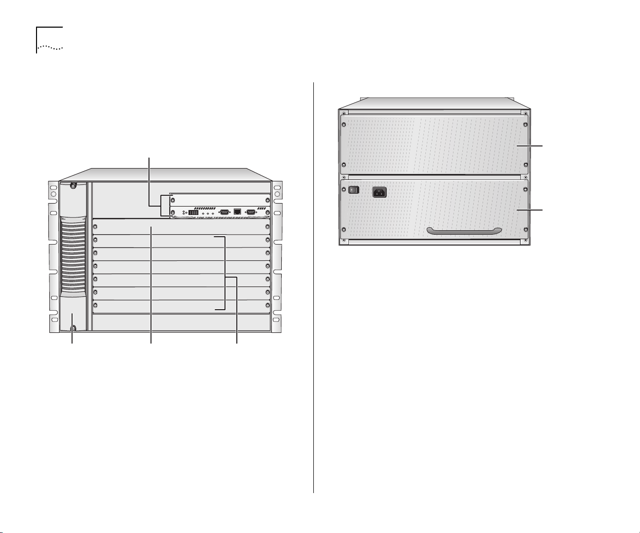
Figure 1 and Figure 2 show the front and the rear,
respectively, of the Switch 4007.
Figure 1
Fan tray
slot
Switch 4007 Chassis Front View
Management
module slots
9
8
7
6
5
4
3
2
1
Switch
fabric module slot
Interface
module slots
Figure 2
Switch Features
The Switch 4007 has the following features:
An intelligent power management system.
■
An intelligent system inventory management
■
system.
An integrated, high-performance, distributed
■
network management system.
Modules and a fan tray that you can install or
■
remove while the switch is operating (called
swapping
Support for 3Com Transcend® Network Control
■
Services for UNIX or for Windows.
Switch 4007 Chassis Rear View
Power
supply
slot 2
Power
supply
(in slot 1)
hot
), for field upgrades and service.
Page 13

Overview
13
Slots for two Enterprise Management Engine
■
(EME) management modules that do not take up
interface module or switch fabric module space.
Switch 4007 starter kits are supplied with with one
management module (Model Number: 3CB9EME)
installed in the lower slot. You can install a second
management module to provide standby
management support.
The management module uses the management
bus to send commands to all installed interface
modules and the switch fabric module and to
collect information from the modules.
A single passive backplane that enables the use of
■
multiple networking technologies, defined by the
type of switch fabric module that is installed.
One slot for a switch fabric module in the chassis
■
to provide optimal network performance.
Gigabit Ethernet starter kits (Model Numbers
■
3C16810 and 3C16811) have one 24-port
Switching Fabric (Model Number: 3CB9FG24T)
preinstalled in slot 7.
Fast Ethernet starter kits (Model Numbers
■
3C16815 and 3C16816) have one 9-port
Switching Fabric (Model Number: 3CB9FG9)
preinstalled in slot 7.
Slots for two power supplies to supply 930 watts
■
with n + 1 redundancy and 1860 watts without
n + 1 redundancy, depending on the type and
quantity of installed modules.
Switch 4007 starter kits have one 930W AC Power
Supply (Model Number: 3CB9EP9) preinstalled in
the lower bay.
Power supplies that you can add or replace while
■
the chassis is running (referred to as
swapping
Slots for six interface modules. In Switch 4007
■
).
starter kits, modules are preinstalled in slots 1 and
2, and the remaining slots are empty.
Packet switching at an aggregated bandwidth of
■
up to 30 Gbps.
Power fault-tolerant mode where you can reserve
■
the power of a single power supply (930 watts) to
act as a backup if the other power supply fails.
One exhaust fan tray (with the power and
■
reliability of four fans) to make sure that the
chassis maintains the optimal temperature for
operation.
Management Features
You can manage the Switch 4007 through:
An out-of-band terminal interface
■
Simple Network Management Protocol (SNMP)
■
3Com Transcend Network Supervisor
■
3Com Transcend Network Control Services
■
A standard Telnet client-to-server application
■
Embedded Web-based management
■
To learn more about management features, see
Chapter 5, “Management Tools”.
warm
Page 14

14
HAPTER
C
BOUT THE SWITCH
1: A
4007
Switch 4007 Starter Kits
3Com enables you to simplify your installation by
selecting from four pre-configured starter kits.
Four configurations are available:
Layer 2 Gigabit Ethernet Starter Kit
■
Model Number: 3C16810
Layer 3 Gigabit Ethernet Starter Kit
■
Model Number: 3C16811
Layer 3 Fast Ethernet (10/100BASE-TX) Starter Kit
■
Model Number: 3C16815
Layer 3 Fast Ethernet (10/100BASE-TX and
■
100BASE-FX) Starter Kit
Model Number: 3C16816
Layer 2 Gigabit Ethernet Starter Kit
Model Number: 3C16810
The Layer 2 Gigabit Ethernet Starter Kit has 18
Gigabit Ethernet ports.
Two 9-port Gigabit Switching Modules (Model
■
Number: 3CB9LG9MC) in slots 1 and 2
4 empty slots (slots 3,4,5,6)
■
You can expand the system to provide 54 Gigabit
Ethernet ports by installing additional modules into
the empty slots.
Layer 3 Gigabit Ethernet Starter Kit
Model Number: 3C16811
The Layer 3 Gigabit Ethernet Starter Kit has 13
Gigabit Ethernet ports.
This starter kit is preinstalled with the following
options:
EME Management Module (Model Number:
■
3CB9EME) in the lower slot
930W AC Power Supply (Model Number:
■
3CB9EP9)
One 24-port Switching Fabric (Model Number:
■
3CB9FG24T) in slot 7
This starter kit is preinstalled with the following
options:
EME Management Module (Model Number:
■
3CB9EME) in the lower slot
930W AC Power Supply (Model Number:
■
3CB9EP9)
One 24-port Switching Fabric (Model Number:
■
3CB9FG24T) in slot 7
One 9-port Gigabit Switching Module (Model
■
Number: 3CB9LG9MC) in slot 1
One 4-port Gigabit MultiLayer Switching Module
■
(Model Number: 3CB9RG4) in slot 2
4 empty slots (slots 3,4,5,6)
■
You can expand the system to provide 49 Gigabit
Ethernet ports by installing additional modules into
the empty slots.
Page 15

Hardware Components
15
Layer 3 Fast Ethernet (10/100BASE-TX) Starter Kit
Model Number: 3C16815
The Layer 3 FEN (10/100BASE-TX) Starter Kit has 48
copper Fast Ethernet ports and 3 GBIC slots for
uplinks.
This starter kit is preinstalled with the following
options:
EME Management Module (Model Number:
■
3CB9EME) in the lower slot
930W AC Power Supply (Model Number:
■
3CB9EP9)
One 9-port Switching Fabric (Model Number:
■
3CB9FG9) in slot 7
One 36-port 10/100BASE-TX Switching Module
■
(Model Number: 3CB9LF36R) in slot 1
One 12-port 10/100BASE-TX MultiLayer Switching
■
Module (Model Number: 3CB9RF12R) in slot 2
4 empty slots (slots 3,4,5,6)
■
You can expand the system to provide 192 Fast
Ethernet ports by installing additional modules into
the empty slots.
Layer 3 Fast Ethernet (10/100BASE-TX and
100BASE-FX) Starter Kit
Model Number: 3C16816
This starter kit is preinstalled with the following
options:
EME Management Module (Model Number:
■
3CB9EME) in the lower slot
930W AC Power Supply (Model Number:
■
3CB9EP9)
One 9-port Switching Fabric (Model Number:
■
3CB9FG9) in slot 7
One 20-port 100BASE-FX Switching Module
■
(Model Number: 3CB9LF20MM) in slot 1
One 12-port 10/100BASE-TX MultiLayer Switching
■
Module (Model Number: 3CB9RF12R) in slot 2
4 empty slots (slots 3,4,5,6)
■
You can expand the system to provide 112 Fast
Ethernet ports by installing additional modules into
the empty slots.
Hardware Components
This section describes the following chassis
components:
Power Supplies
■
Fan Tray
■
Modules
■
The Layer 3 FEN (10/100BASE-TX and 100BASE-FX)
Starter Kit has 12 copper and 20 fiber Fast Ethernet
ports and 3 GBIC slots for uplinks.
Page 16
16
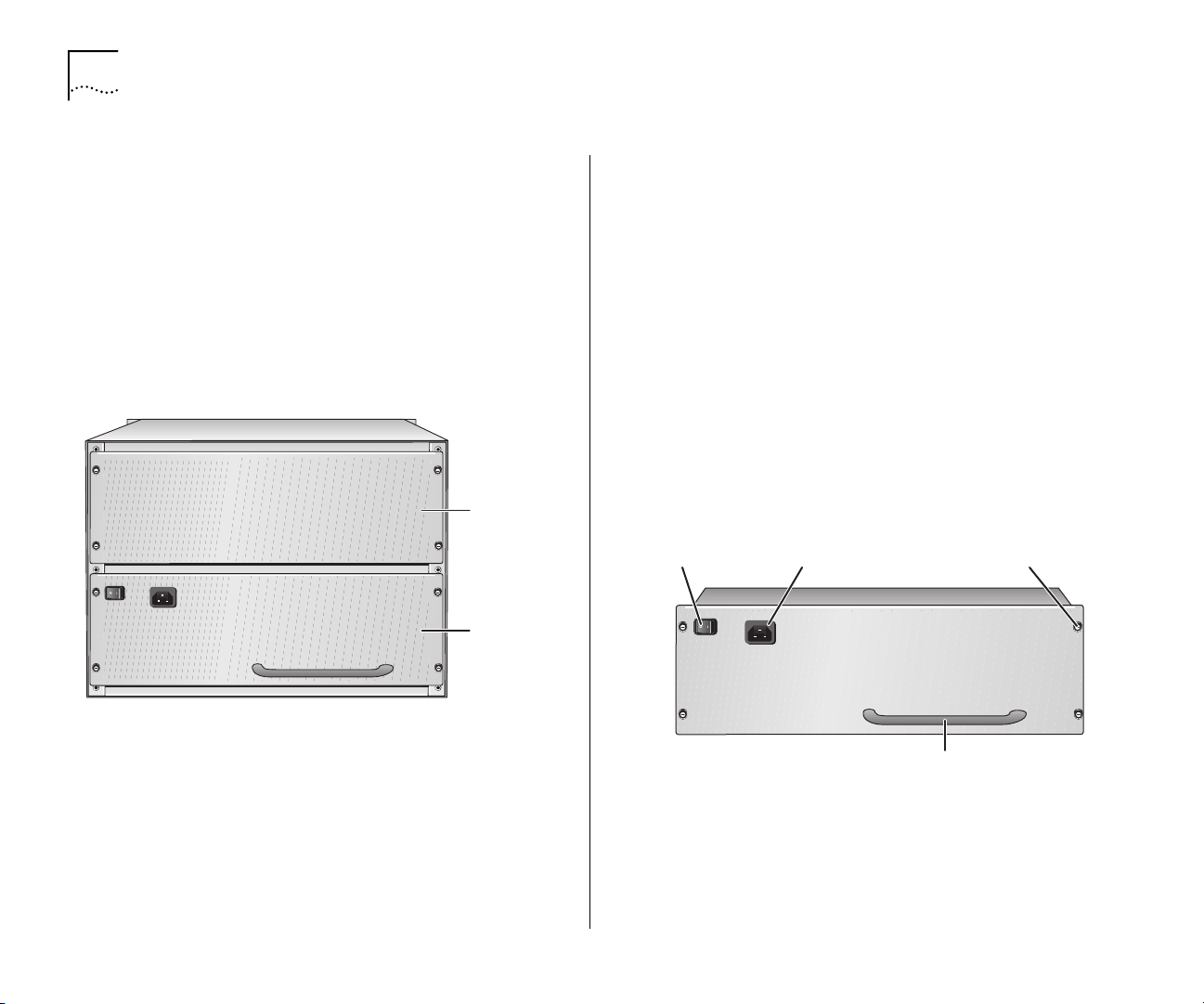
Spring-loaded
screw
Power supply
handle
Standby/On
switch
AC input
socket
HAPTER
C
BOUT THE SWITCH
1: A
4007
Power Supplies
The Switch 4007 can contain two back-loading,
930-watt, modular AC power supplies (Model
Number 3CB9EP9). The power supplies provide
power to the management modules, switch fabric
module, interface modules, fans, and backplane.
Figure 3 shows a 930-watt AC power supply in a
Switch 4007 chassis.
Figure 3
930-watt AC Power Supply in the Switch 4007
Power
supply
slot 2
Power
supply
(in slot 1)
930-watt AC Power Supply
Switch 4007 power supplies are autosensing. Each
power supply (Figure 3) can automatically sense the
type of input voltage to which it is being connected at
the electrical outlet.
The power supplies are load sharing in that all power
supplies provide an equal amount of the load current.
Each 930-watt power supply has its own power cord
and is shipped separately from the chassis. The type
of power cord depends on your country location.
Figure 4 shows the 930-watt AC power supply for the
Switch 4007 chassis.
Figure 4
930-watt AC Power Supply for the Switch 4007
You can add or replace power supplies while the
chassis is running (referred to as
warm swapping
Chapter 6, “Maintaining the Switch 4007”, for
instructions about how to replace a faulty power
supply.
). See
Page 17
Hardware Components
1
2
3
4
5
6
7
8
9
17
Fan Tray
The Switch 4007 chassis contains one fan tray, which
contains four fans (Model Number 3CBEF7). The fans
cool the interface modules, the switch fabric module,
and the management modules.
Figure 5
Spring-loaded
screw
Fan tra y
handle
Spring-loaded
screw
Switch 4007 Chassis Fan Tray
Module Slots in the Switch 4007 Chassis
You insert modules horizontally into the chassis. Slots
are numbered from bottom to top, with the bottom
slot being number 1.
The chassis contains:
Management slots
■
— There are two slots (slot 8
and slot 9) for management modules:
The Enterprise Management Engine (EME) is an
■
SNMP-based network management module
that manages and controls the Switch 4007 and
its modules. The management module is the
primary communication mechanism into the
switch and modules. You manage other
intelligent modules within the chassis through
the management module.
The Enterprise Management Controller (EMC)
■
module provides standby controller functions
for an EME in a Switch 4007.
Payload slots
■
— There are six slots (slot 1 through
slot 6) for interface modules. The interface
modules offer a selection of packet-based or
cell-based interfaces that work with the switch
fabric module.
Switch fabric slots
■
a Gigabit Ethernet Switch Fabric Module, which is
the central backplane aggregator for the Switch.
To learn more about management, switch fabric, and
Fast Ethernet and Gigabit Ethernet interface modules,
see Chapter 2, “Switch 4007 Modules”.
— There is one slot (slot 7) for
Page 18

18
HAPTER
C
BOUT THE SWITCH
1: A
4007
Page 19

2
WITCH
S
4007 M
ODULES
This chapter contains the following topics:
Overview
■
Switch Fabric Modules
■
Management Modules
■
Fast Ethernet Modules
■
Gigabit Ethernet Modules
■
GBIC Transceivers
■
Slot Restrictions
■
Management Access
■
Where to Go from Here
■
Overview
The 3Com® Switch 4007 is a high performance,
high-density, aggregation switch. The Switch 4007
has a modular 7-slot chassis that contains slots for the
following types of modules:
Management Modules (see page 21)
■
The EME management module exchanges
information with all modules through the
management bus. The EME uses the management
bus to send commands to all chassis modules and
to collect information from interface modules.
The Switch 4007 is required to have a minimum of
one EME (Enterprise Management Engine)
management module. You can install a second
EME for redundant management operation.
Switch Fabric Modules (see page 20)
■
The Gigabit Ethernet (GEN) switch fabric module is
the central backplane aggregator for the chassis.
Switch fabric modules fit into slot 7 of the
Switch 4007 chassis.
Fast Ethernet Modules (see page 22) and Gigabit
■
Ethernet Modules (see page 23)
Interface modules pass data through the switch
fabric module. The data may get sent back out to
other modules or sent out through a switch fabric
module front panel port to another device.
The Switch 4007 contains six slots for interface
modules. Fast Ethernet or Gigabit Ethernet
modules can occupy every slot except slot 7. The
six interface modules access five 2 Gbps serial
channels, which are wired to one dedicated switch
fabric module slot.
Page 20
20
HAPTER
C
2: S
WITCH
4007 M
ODULES
Switch Fabric Modules
The Switch 4007 supports 9-port and 24-port Gigabit
Ethernet Switch Fabric modules. Both switch fabric
modules fit into slot 7 of the Switch 4007 chassis.
3Com enables you to simplify your installation by
selecting from four pre-configured starter kits.
Fast Ethernet starter kits are pre-configured with
■
one 9-port Switching Fabric (Model Number:
3CB9FG9) in slot 7.
Gigabit Ethernet starter kits are pre-configured
■
with one 24-port Switching Fabric (Model Number:
3CB9FG24T) in slot 7.
The Switch Fabric modules support the following key
features:
18 Gbps or 48 Gbps switching capacity
■
Hot-swapping of modules
■
IEEE 802.1D Spanning Tree Protocol bridging for
■
Gigabit Ethernet
Multicast packet firewall to limit broadcast storms
■
Port trunking support for 12 groups, with up to six
■
ports in a group
IEEE 802.1Q VLAN tagging for up to 126 groups of
■
port-based virtual LANs (VLANs)
Embedded Simple Network Management Protocol
■
(SNMP) management agent
Support for four RMON-1 groups: Ethernet
■
Statistics, History, Events, and Alarms
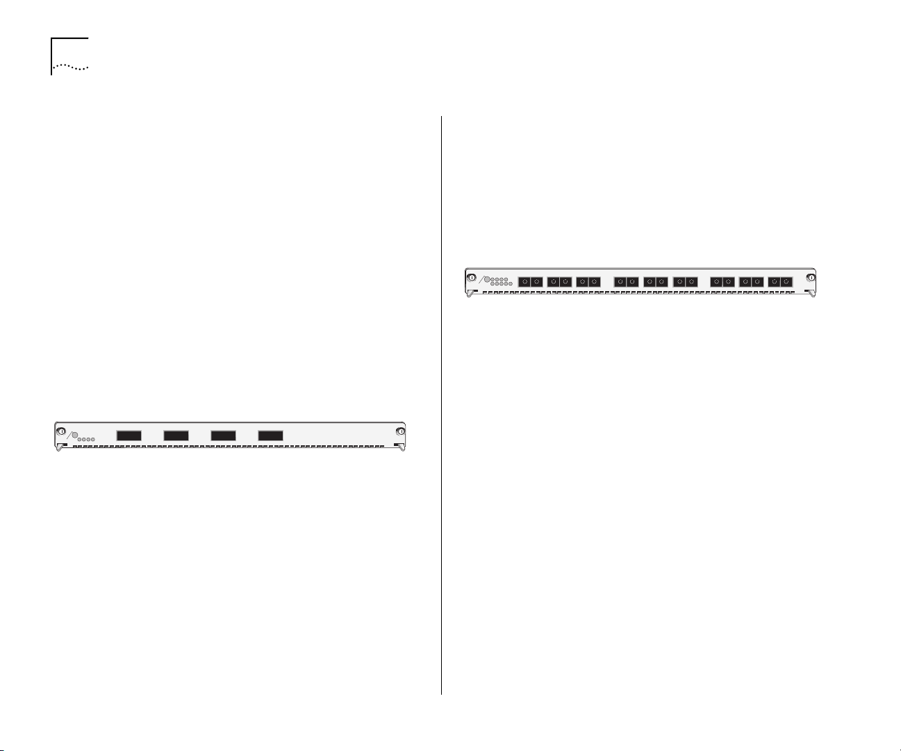
9-port Gigabit Ethernet Switch Fabric
Model Number: 3CB9FG9
The 9-port Gigabit Ethernet (GEN) Switch Fabric
Module is optimized for use in wiring closets. The
module has six non-blocking Gigabit Ethernet ports
that connect directly to the chassis backplane to
provide high-speed, low-latency connectivity between
Switch 4007 interface modules. Its front panel
features three non-blocking Gigabit Interface
Converter (GBIC) interface ports that accept optional
GBIC transceivers (see “GBIC Transceivers” on
page 25). Figure 6 shows the front panel.
Front Panel of 9-port Switch Fabric Module
T
L
N
E
O
N
A
R
P
F
9
X
X
X
T
R
R
8
7
T
E
A
S
T
S
D
O
M
I
R
P
Figure 6
C
2
1
345
678
To learn more about this module, refer to the
Gigabit Ethernet Switch Fabric Module Quick Start
on the Online Manuals CD-ROM.
Guide
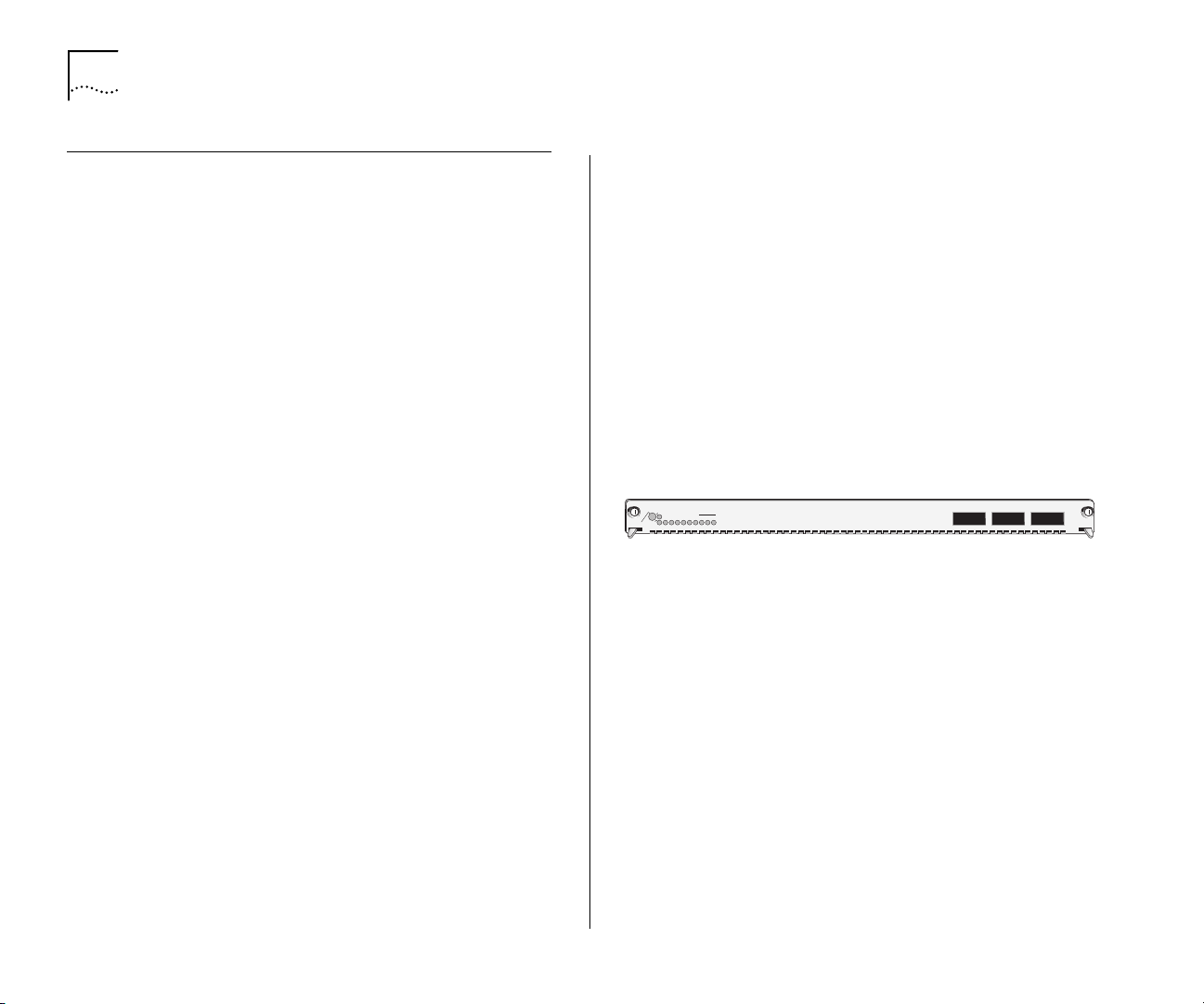
24-port Gigabit Ethernet Switch Fabric
Model Number: 3CB9FG24T
The 24-port Gigabit Ethernet (GEN) Switch Fabric
Module is designed for use in network backbones,
data centers, and other high-density network
segments. The 24-port GEN Switch Fabric Module has
24 nonblocking Gigabit Ethernet ports that connect
to the chassis backplane to provide high-speed,
low-latency connectivity between Switch 4007
switching modules. Figure 7 shows the front panel.
X
T
X
X
R
T
9
9-Port
3CB9FG9
Page 21
Management Modules
21
Front Panel of 24-port Switch Fabric Module
0
4
4
6
8
2
1
1
1
2
2
2
3
5
7
9
1
3
1
1
1
1
2
2
T
A
S
T
S
D
O
M
Figure 7
C
E
0
1
1
I
123456789
R
1
P
2
1
To learn more about this module, refer to the
Gigabit Ethernet Switch Fabric Module Quick Start
on the Online Manuals CD-ROM.
Guide
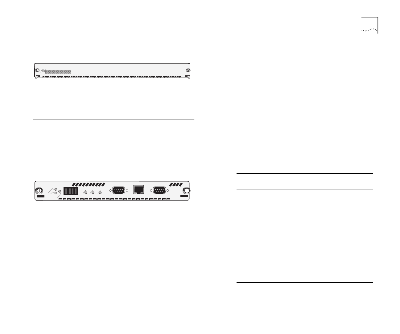
Management Modules
The Switch 4007 chassis contains two slots
(slots 8 and 9) for Management Modules
management modules. These modules do not occupy
module payload slots. Figure 8 shows the front panel.
Figure 8
E
IV
T
C
Y
A
B
T
S
B
0
1
You can communicate through an RS-232 connector
(for connection to a terminal) or an RJ-45 port (for
connection to Ethernet networks) on the front panel
of the EME to configure and report on switch and
module operation.
The Switch 4007 EME is an SNMP-based network
management module that allows you to configure
and manage the Switch 4007 chassis and modules.
The EME backplane services generate, control, and
monitor the Switch. The management modules
provide power management functions.
Front Panel of EME Management Module
T
IS
E
S
T
Y
E
S
S
E
L
E
M
A
S
P
E
R
E
H
S
R
C
-T
D
You manage the switch through:
The EME command interface, which you access
■
3CB9FG24T
24-Port
through the serial port, or through SNMP (Simple
Network Management Protocol).
The Switch 4007 Web Management suite of
■
applications.
3Com Transcend Network Control Services.
■
An EME combines the functions of a management
module and a controller module. You can install a
second EME to provide standby management support
if the first EME is unavailable for any reason.
Table 3 describes the EME access mechanisms.
.
Ta b le 3
Access
Mechanism
2
3
2
S
R
-T
B
0
1
X
U
A
3CB9EME
Terminal Connect directly to the
Modem Access the command
IP Access the command
EME Access Mechanisms
Allows you to Using
command interface.
interface from remote
sites.
interface using the
rlogin or telnet
commands, or use an
external SNMP
management
application to
communicate with the
embedded SNMP agent.
RS-232 serial
port
Auxiliary RS-232
serial port
10BASE-T
Ethernet port
assigned to an IP
interface
Page 22
22
HAPTER
C
2: S
WITCH
4007 M
ODULES
For information about how to install the EME and
how to perform an initial configuration, see the
Enterprise Management Engine Quick Start Guide
the Online Manuals CD-ROM.
Fast Ethernet Modules
The frame-based switching modules are intelligent
Layer 2 and Layer 3 modules that have their own
embedded agent. These modules are physically
connected to the backplane ports of the switch fabric
module in the chassis. These modules switch between
the front panel ports and the backplane ports.
Switching interface modules provide network
connectivity functions.
Fast Ethernet Interface Modules are available in these
port configurations:
20-port 100BASE-FX (MT-RJ) Fast Ethernet Layer 2
■
Switching Module
36-port 10/100BASE-TX Fast Ethernet RJ-45 Layer
■
2 Switching Module
12-port 10/100BASE-TX Fast Ethernet MultiLayer
■
Switching Module
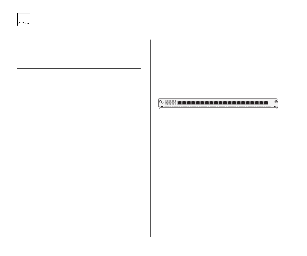
20-port 100BASE-FX (MT-RJ) Fast Ethernet Layer 2 Switching Module
Model Number: 3CB9LF20MM
The 100BASE-FX (MT-RJ) Fast Ethernet Layer 2
Switching Module has twenty 100 Mbps Ethernet
fiber-optic ports with MT-RJ connectors on its front
panel and two 1-Gigabit ports for connection to the
on
chassis backplane. It operates as a Layer 2 switch and
occupies a single interface module slot in the
Switch 4007 chassis.
Figure 9 identifies the components on the front panel
of the module. The front panel ports on the module
are numbered 1 through 20. The two 1-Gigabit ports
on the back of the module are numbered 21 and 22.
Figure 9
A
A
T
T
S
S
D
D
O
O
M
M
Front Panel of Module 3CB9LF20MM
4
4
1
1
T
T
7
7
5
5
4
4
3
3
1
2
6
1
2
6
X
X
X
X
4
3
2
1
4
3
2
1
X
X
X
X
8
7
6
5
8
7
6
5
X
X
X
1
0
X
9
1
0
1
1
9
1
1
X
X
5
4
3
2
2
4
3
1
1
1
1
1
1
1
To learn more about this module, refer to the
X
X
7
6
6
5
1
1
1
1
X
X
X
X
0
9
8
8
7
1
1
1
3CB9LF20R
0
9
2
1
2
1
3CB9LF20MM
20-Port
100BASE-FX (MT-RJ) Fast Ethernet Layer 2 Switching
Module Quick Start Guide
on the Online Manuals
CD-ROM.
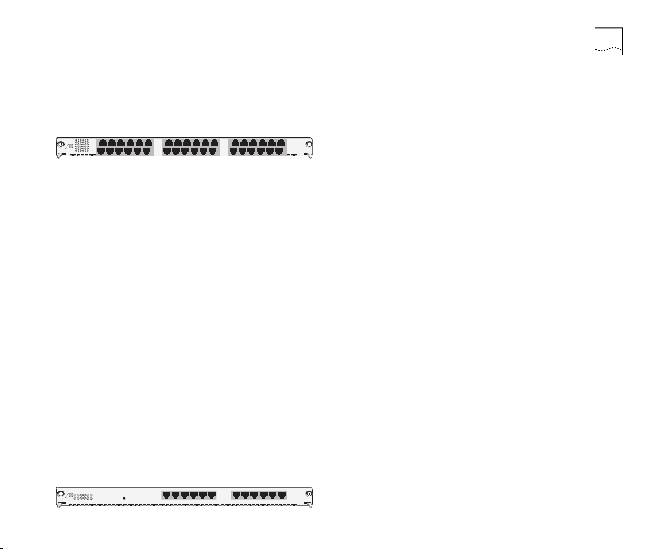
36-port 10/100BASE-TX Fast Ethernet RJ-45 Layer 2 Switching Module
Model Number: 3CB9LF36R
The 10/100BASE-TX Fast Ethernet RJ-45 Layer 2
Switching Module (36-port FEN RJ-45 Switching
Module) has thirty-six 10/100 Mbps Ethernet ports
with RJ-45 connectors on its front panel, and two
1-Gigabit ports on the back for connection to the
chassis backplane. It operates as a Layer 2 switch and
occupies a single interface module slot in the
Switch 4007 chassis.
Page 23
Gigabit Ethernet Modules
23
Figure 10 identifies the components on the front
panel of the module.
Figure 10
6
1
3
3
T
X
A
T
7
S
D
O
M
X
1
6
1
To learn more about this module, refer to the
Front Panel of Module 3CB9LF36R
X
9
1
X
3
1
X
1
3
X
5
2
36-Port
10/100BASE-TX Fast Ethernet RJ-45 Layer 2 Switching
Module Quick Start Guide
on the Online Manuals
CD-ROM.
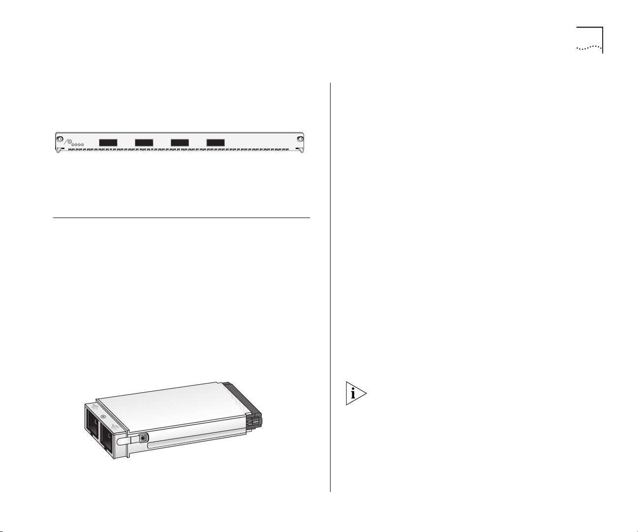
12-port 10/100BASE-TX Fast Ethernet MultiLayer Switching Module
Model Number: 3CB9RF12R
The 12-port 10/100BASE-TX Fast Ethernet MultiLayer
Switching Module is a multiprotocol module designed
for the Switch 4007. The module has twelve
10/100BASE-TX Fast Ethernet front panel ports that
provide a 100 Mbps connection over UTP-Category 5
cables, and one nonblocking Gigabit Ethernet port
that connects through the backplane to the switch
fabric module. The module has two groups of six
ports, operates as a Layer 3 router switch, and
occupies a single interface module slot in the
Switch 4007 chassis.
Figure 11 identifies the components on the front
panel of the module.
Figure 11
Front Panel of Module 3CB9RF12R
3CB9LF36R
To learn more about this module, refer to the
10/100BASE-TX Fast Ethernet Layer 3 Switching
Module Quick Start Guide
CD-ROM.
Gigabit Ethernet Modules
The Gigabit Ethernet (GEN) Interface Modules are
two-port interface modules for the 3Com
Switch 4007. The GEN interface modules serve as a
2–Gigabit data channel between the Gigabit Ethernet
Switch Fabric Module and other 802.3z–compliant
Gigabit Ethernet devices. GEN Interface Modules use
SC connectors.
Because Gigabit Ethernet interface modules are not
intelligent, you cannot access them directly; all
communication takes place through the switch fabric
module. GEN interface modules serve as a
two-Gigabit data channel between the GEN Switch
Fabric Module and other 802.3z-compliant Ethernet
devices.
For information about how to install these modules,
see the module’s
with each module.
Gigabit Ethernet Interface Modules are available in
these port configurations:
4-port Gigabit Ethernet Interface Module
■
9-port 1000BASE-SX Gigabit Ethernet Layer 2
■
Switching Module
Quick Start Guide
12-Port
on the Online Manuals
that is shipped
4-port Gigabit MultiLayer Switching Module
T
1
0
2
A
1
1
9
1
8
7
T
S
D
O
M
5
4
3
1
2
6
4
3
2
1
6
5
0
2
1
9
8
7
1
1
1
3CB9RF12R
■
Page 24
24
HAPTER
C
2: S
WITCH
4007 M
ODULES
4-port Gigabit Ethernet Interface Module
Model Number: 3CB9LG4
The 4-port Gigabit Ethernet (GEN) Interface Module
(GBIC) is an interface for gigabit rate data between
the Switch 4007 chassis backplane and other
802.3z-compliant Gigabit Ethernet devices. The
module provides four Gigabit Ethernet fiber-optic
connections on the front panel, using plug-in Gigabit
Interface Converter (GBIC) transceivers. The module
occupies a single interface module slot in the
Switch 4007 chassis.
Each module has four ports on the front panel.
Figure 12 identifies the components on the front
panel of the module.
Front Panel of Module 3CB9LG4
X
R
X
X
R
T
1
2
X
X
T
X
R
T
3
X
X
R
T
4
T
A
T
S
D
O
M
2
1
Figure 12
4
3
To learn more about this module, refer to the
Gigabit Ethernet Interface Module (GBIC) Quick Start
on the Online Manuals CD-ROM.
Guide
9-port 1000BASE-SX Gigabit Ethernet Layer 2 Switching Module
Model Number: 3CB9LG9MC
The 9-port 1000BASE-SX Gigabit Ethernet Layer 2
Switching Module can switch Gigabit Ethernet (GEN)
connections to corporate backbones and servers. The
module has nine 1000BASE-SX GEN front panel
ports. It has 3 backplane ports for connection to the
3CB9LG4
4-Port
24-port GEN Switch Fabric Module, and 1 backplane
port for connection to the 9-port GEN Switch Fabric
Module. The module occupies a single interface
module slot in the Switch 4007 chassis.
Figure 13 identifies the components on the front
panel of the module.
Front Panel of Module 3CB9LG9MC
X
X
X
X
X
R
T
T
R
2
1
3
X
X
R
T
X
X
R
R
T
4
5
X
R
T
6
X
R
T
T
7
8
X
X
X
T
A
7
6
T
S
D
O
M
1
2
Figure 13
X
T
9
8
5
4
3
To learn more about this module, refer to the
1000BASE-SX Gigabit Ethernet Layer 2 Switching
Module Quick Start Guide
on the Online Manuals
CD-ROM.
4-port Gigabit MultiLayer Switching Module
Model Number: 3CB9RG4
The 4-port Gigabit Ethernet Layer 3 Switching
Module (GBIC) for the Switch 4007 provides
high-port-density, line speed, Gigabit Ethernet
switching and routing on backbone networks running
at Open Systems Interconnection (OSI) Layer 3.
The module provides 4 Gigabit Interface Converter
(GBIC) ports on the front panel that can be either
1000BASE-LX (single-mode fiber) or 1000BASE-SX
(multimode fiber). 4 Gigabit Ethernet ports connect
the module to the chassis backplane.
X
R
X
X
R
T
9
9-Port
3CB9LG9MC
Page 25
GBIC Transceivers
25
Figure 14 identifies the components on the front
panel of the module.
Front Panel of Module 3CB9RG4
1
T
A
T
S
D
O
M
123
Figure 14
4
To learn more about this module, refer to the
Gigabit Ethernet Layer 3 Switching Module (GBIC)
Quick Start Guide
GBIC Transceivers
The Gigabit Interface Converter (GBIC) ports on your
system connect to Gigabit Ethernet networks through
a GBIC transceiver (Figure 1), providing a high-speed
connection over fiber-optic cable. The transceiver
connects to the network using a fiber-optic duplex
subscriber connector (SC). You can remove and
replace the transceiver with the system powered on,
which is called hot-swapping.
Figure 15
GBIC Fiber-Optic Transceiver
2
3
4
on the Online Manuals CD-ROM.
3CB9RG4
4-Port
The following transceivers are available:
SX GBIC Transceiver
■
LX GBIC Transceiver
■
70-km Long Haul GBIC Transceiver
■
SX GBIC Transceiver
Model Number: 3CGBIC91
The 1000BASE-SX GBIC transceiver supports a direct
connection to 62.5-micron or 50-micron multimode
fiber-optic cable.
To learn more about this transceiver, refer to the
Transceiver Installation Guide
CD-ROM.
LX GBIC Transceiver
Model Number: 3CBGIC92
The 1000BASE-LX GBIC transceiver supports a direct
connection to single-mode fiber-optic cable, or
connection to multimode fiber through a conditioned
launch cable.
GBIC
on the Online Manuals
To ensure optimal performance, compatibility, and
regulatory compliance, use only conditioned launch
cables that 3Com supports. For a list of supported
conditioned launch cables, see this 3Com Web site:
http://www.3Com.com/gigabit_ethernet/gbics
To learn more about this transceiver, refer to the
Transceiver Installation Guide
on the Online Manuals
GBIC
CD-ROM.
Page 26

26
HAPTER
C
2: S
WITCH
4007 M
ODULES
70-km Long Haul GBIC Transceiver
Model Number: 3CGBIC97
The 70-km Gigabit Ethernet GBIC Fiber-Optic
Transceiver connects to the network using a
fiber-optic duplex SC connector.
To learn more about this transceiver, refer to the
70-km Gigabit Ethernet GBIC Transceiver Installation
on the Online Manuals CD-ROM.
Guide
Slot Restrictions
Table 4 lists slot restrictions in the Switch 4007
chassis.
Ta b l e 4
Module type Slot number
Management modules 8 and 9
Switch fabric module 7
Interface modules 1, 2, 3, 4, 5, 6
Slot Restrictions
Management Access
You can access and manage your Switch 4007
modules using several methods:
Administration Console
■
Web Management suite of applications
■
External SNMP-based network management
■
application, such as Transcend
Services
®
Network Control
The Administration Console and most of Web
Management are embedded parts of the software
and are available for immediate use to manage your
modules.
Administration Console Access
To manage the module from the Administration
Console:
Log in to the EME.
1
For information about logging in to the EME, see the
Enterprise Management Engine User Guide.
At the prompt, enter:
2
connect <slot>.1
Where
<slot>
is the chassis slot number of the
module that you want to manage, and the number
after the decimal point is a subslot number (which is
always 1).
The Administration Console displays the top-level
menu prompt. For example, if you installed a 20-port
100BASE-FX Fast Ethernet Switching Module in slot
4, then the prompt appears as follows:
CB9000@4.1 [20-E/FEN-FX-L2] ():
Enter commands to manage the module.
3
For example, to display a module baseline, enter:
module baseline display
For more information about Administration Console
module commands, see the multiplatform
Reference Guide.
Command
Page 27

Web Management Access
Web Management applications are an embedded
part of the Switch 4007. They include Web Console,
DeviceView, and Performance monitoring tools.
Additional installable applications include online Help.
After you have set up your IP address for the Switch,
you can access the Web Management applications
directly in your Web browser by entering the IP
address. For information about setting up your IP
address, see the
Quick Start Guide
Enterprise Management Engine
.
For additional information about Web Management,
see Chapter 5, “Management Tools”.
Where to Go from Here
For more information about Switch 4007 see the
following documents, which are supplied in PDF
format on the Online Manuals CD-ROM:
Where to Go from Here
■
12-Port 10/100BASE-TX Fast Ethernet Layer 3
Switching Module Quick Start Guide
■
4-Port Gigabit Ethernet Interface Module (GBIC)
Quick Start Guide
■
9-Port 1000BASE-SX Gigabit Ethernet Layer 2
Switching Module Quick Start Guide
■
4-Port Gigabit Ethernet Layer 3 Switching
Module (GBIC) Quick Start Guide
Switch fabric modules
■
■
24-Port Gigabit Ethernet Switch Fabric Module
Quick Start Guide
■
9-port Gigabit Ethernet Switch Fabric Module
Quick Start Guide
GBIC transceivers
■
■
GBIC Transceiver Installation Guide
■
70-km Gigabit Ethernet GBIC Transceiver
Installation Guide
27
Management modules
■
■
Enterprise Management Engine Quick
Start Guide
■
Switch 4007 Implementation Guide
■
Switch 4007 Command Reference Guide
Interface modules
■
■
20-Port 100BASE-FX (MT-RJ) Fast Ethernet Layer
2 Switching Module Quick Start Guide
■
36-Port 10/100BASE-TX Fast Ethernet RJ-45
Layer 2 Switching Module Quick Start Guide
The Switch 4007 is based on 3Com
CoreBuilder
®
9000 technology and supports a range
of CoreBuilder 9000 components.
The Quick Start Guides that are supplied with many
product options describe installation and setup procedures for the CoreBuilder 9000. However, you can
install supported components into a Switch 4007
chassis as you would install them into the CoreBuilder
9000 7-slot chassis.
Page 28

28
HAPTER
C
2: S
WITCH
4007 M
ODULES
Page 29

3
NSTALLING THE
I
WITCH
S
4007
This chapter contains the following topics:
Site Requirements for the Switch 4007
■
Preinstallation Guidelines
■
Installing the Chassis
■
Figure 16 summarizes the installation procedure.
For a Switch 4007 starter kit, you can simplify
the installation proceedure because the chassis is
pre-configured with one power supply, one
management module, one switch fabric module,
and two interface modules.
Figure 16
Troubleshoot Problems
•
Command Reference Guide
•
Implementation Guide
Configure the Switch for
Management
•
Command Reference Guide
•
Implementation Guide
Power On the Switch
• Chapter 4 (In this guide)
Switch 4007 Installation Procedure
Administer and Operate
the Switch
•
Command Reference Guide
•
Implementation Guide
Install Interface Modules
• Interface module quick start or
getting started guides
•
Interface module user guides
(if available)
Determine Site Requirements
• Chapter 3 (In this guide)
12
11
10
9
Install a Switch Fabric
8
Module
• Switch fabric module quick
start or getting started guides
• Switch fabric module
user guides (if available)
7
6
5
4
3
2
1
9
8
Switch 4007
Unpack the Switch 4007
Chassis
1
• “Unpacking Instructions”
(In this guide)
Install the Chassis and
Optional Devices
• Chapter 3 (In this guide)
Install a Power Supply
•
7-Slot Chassis Power Supply
Installation Guide
Install a Power Cable
•
7-Slot Chassis Power Supply
Installation Guide
Install an EME Management
Module
•
Enterprise Management Engine
Quick Start Guide
7
2
3
4
5
6
Page 30

30
HAPTER
C
NSTALLING THE SWITCH
3: I
4007
Site Requirements for the Switch 4007
This section describes the following site requirements
for setting up your Switch 4007:
Location Requirements
■
Precautionary Guidelines
■
Ventilation Requirements
■
Power Requirements
■
Safety Information
■
Location Requirements
Install a Switch 4007 in an area that meets the
following requirements:
Ambient (room) temperature: 0 °C to 50 °C (32 °F
■
to 122 °F). The default internal operating
temperature threshold for the Switch 4007 is
approximately 60 °C (140 °F).
Relative humidity: between 10 and 90 percent,
■
noncondensing.
The table or rack on which you mount the chassis
■
supports at least three times the weight of a fully
loaded chassis.
The recommended minimum space that is required
■
between the front of the chassis and another
vertical surface (such as a rack door) is 8 cm (3 in.).
There is a sufficient amount of space on each side
■
of the Switch 4007 chassis to accommodate any
cables along the side of the chassis.
There is at least 7 cm (2.76 in.) on each side of the
■
Switch 4007 chassis to ensure proper cooling in
the chassis.
There is at least 91.4 cm (36 in.) in back of the
■
chassis to:
Remove and replace power supplies.
■
Maintain proper cooling.
■
If the chassis is the first device in your rack, then
■
mount it about 10.2 cm (4 in.) up from the floor.
The power source is within approximately 2 meters
■
(6.6 feet) of the location where you plan to install
the Switch 4007.
Each of the power supplies connects to a
■
dedicated circuit. Do not connect the power
supplies to a power strip.
The surface on which you want to locate the
■
Switch 4007 chassis is level.
Have the required cables available at your site to
■
make physical connections in your switch
configuration.
Precautionary Guidelines
Ambient temperature for the Switch 4007 must
■
not exceed 50 °C (122 °F).
Safety regulations stipulate that for a Switch 4007
■
chassis, the table, shelf, or rack on which the
switch rests can support at least 115.65 kg (255
lb), which is three times the weight of a fully
loaded Switch 4007 chassis.
Page 31

For rack installations, the selected rack is grounded
■
in accordance with the rack manufacturer’s
recommendations.
To reduce the possibility of personal injury or
■
serious damage to the chassis, use
people
to install the chassis. This is especially
at least two
important for rack installations, because you must
hold the chassis in place while you secure the
chassis to the rack.
Bolt the rack to the floor.
■
Make certain that the rack is properly aligned and
■
squared. Use a framing tool to ensure that the rack
is squared.
Brace the top of the rack against the wall.
■
Provide sufficient space in front of and behind the
■
chassis so that you can service it easily and provide
proper ventilation.
Provide at least 7 cm (2.76 in.) on each side of
■
the Switch 4007 chassis to ensure proper
cooling in the chassis.
Provide at least 91.4 cm (36 in.) in back of the
■
switch to remove and replace power supplies in
the Switch 4007 chassis.
Use the following guidelines to tighten screws to
■
Torque Specification:
Faceplate thumbscrews — 3-5 in/lb
■
(inch-pounds)
#10 screws for holding the chassis onto the
■
rail — 22-25 in/lb
Power supplies to the chassis — 5-7 in/lb
■
Site Requirements for the Switch 4007
31
To ensure that you tighten screws to Torque
Specification, use a torque screwdriver.
The following list shows the amount of rack space
that is needed to install a Switch 4007 chassis in a
Telco rack or a Metric rack.
Height — 30.98 cm / 12.2 in.
■
The height of the chassis, allowing for some
extension beyond the location of the upper and
lower unit dividing lines.
Telco Rack Unit — 7 RU
■
The unit of measure is 1 Rack Unit (1.75 in. or
4.45 cm).
Metric Rack Unit — 12.5 SU
■
The unit of measure is 1 System Unit
(25 millimeters).
Front clearance — 8 cm / 3 in.
■
This is the recommended minimum space required
between the front of the chassis and another
vertical surface (such as a rack door).
Rack-Mount Installation Recommendations
Use at least two people to install any chassis.
Before you install a chassis into a rack, make certain
that the rack you are using is properly aligned and
squared. Use a framing square to ensure that the rack
is squared. Doing so makes installing the chassis into
the rack easier.
Page 32

32
1
2
3
4
5
6
7
8
9
HAPTER
C
NSTALLING THE SWITCH
3: I
4007
WARNING:
To maintain proper cooling in the chassis
and to maintain safety compliance, make certain that
blank faceplates cover any empty slots.
If you install more than one chassis in a rack, install
■
the bottom chassis first. Make certain that there is
sufficient space between the bottom chassis and
the top chassis.
If you install the chassis in a Metric rack slot, install
■
the rack-mount clips and screws in the closed slots
of the rack-mount flanges. If you install the chassis
in Telco rack slots, position the chassis and then
install the screws and rack-mount clips in the open
slots.
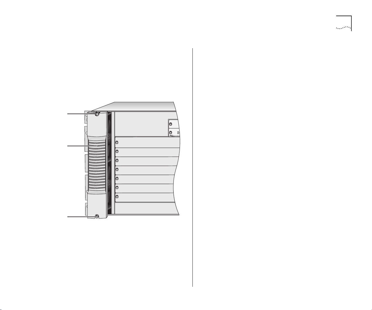
Figure 17 shows the Telco and Metric slots and the
location of the preinstalled rack-mount flange on a
Switch 4007 chassis.
Figure 17
Preinstalled Rack-mount Flange Location and Slot
Types on the Switch 4007 Chassis
Preinstalled
flange pin
Telco rack
open slot
Metric rack
closed slot
Page 33

Site Requirements for the Switch 4007
33
Ventilation Requirements
This section describes ventilation requirements for the
Switch 4007. The chassis contains one fan tray that
contains four fans.
To ensure that installed fans are able to provide
adequate ventilation, maintain at least 7 cm (2.76 in.)
between the sides of the Switch 4007 chassis and the
nearest wall (or other vertical surface). Also provide at
least 91.4 cm (36 in.) behind the chassis to be able to
remove and replace power supplies in the
Switch 4007 chassis.
When you face the front of the Switch 4007 chassis,
the inlet is on the right and the exhaust is on the left.
CAUTION:
Operate a Switch 4007 chassis with four
fans running. If one fan in the fan tray fails, replace
the fan tray as soon as possible.
Power Requirements
This section list power requirements for the 930-watt
AC (Model Number 3CB9EP9) power supply.
The Switch 4007 chassis can contain two modular
930-watt power supplies. The 930-watt power
supplies provide AC power to the Switch. The
930-watt power supplies are autosensing. Each
power supply can automatically sense the type of
input voltage to which it is being connected at the
electrical outlet.
Table 5 lists power requirements for each country.
Ta b le 5
Location Volts Hz Ampere
Asia 220 - 240 Volts 50 Hz 15-ampere
Australia 220 - 240 Volts 50 Hz 10-ampere
Canada 120 Volts 60 Hz 20-ampere
Europe 220 - 230 Volts 50 Hz 16-ampere
Japan 100 Volts 50/60 Hz 15-ampere
South Africa 220 - 250 Volts 50 Hz 16-ampere
U.K. 240 Volts 50 Hz 13-ampere
U.S.A. 120 Volts 60 Hz 20-ampere
Power Requirements Per Country
One power cord per power supply is required. The
power cord that you require depends on your country
location.
Table 6 lists the power cords for each country.
Ta b le 6
Location Power Cord Type
Asia C19/AS3112
Australia C19/AS3112 special- 10A - C19
Canada C19/NEMA 5-20P
Europe C19/CEE7
Japan C19/NEMA 5-15P
South Africa C19/SABS164
U.K. C19/BS1363A
U.S.A. C19/NEMA 5-2 OP
Power Cord Description for Your Location
Page 34

34
CLASS 1
LASER PRODUCT
HAPTER
C
NSTALLING THE SWITCH
3: I
4007
Safety Information
This section lists warning notices to read before you
install the Switch 4007 and its components.
WARNING:
by trained service personnel.
WARNING:
and maintain safety compliance, make certain that
blank faceplates cover any empty slots.
WARNING:
the Switch. Do not place hands or objects into the
switch or touch components on an inserted module.
WARNING:
table, shelf, or rack must be able to support at least
three times the weight of a fully loaded Switch. A
fully loaded Switch 4007 chassis weighs
approximately 38.55 kg (85 lb). Therefore, the
selected table or shelf must support at least 115.65
kg (255 lb).
Denmark Safety Certification
The following warning is required for Denmark safety
certification:
The Switch 4007 must be installed only
To maintain proper cooling in the chassis
Hazardous energy levels exist inside of
Safety regulations state that the selected
WARNING:
Ved brug i Danmark, skal hver 3CB9EP9
stromforsyning modtage strom fra en separat,
dedikeret stikkontakt med en 16-ampere sikring i
installationen.
Laser Warning
The following warning is required when you install
fiber-optic communication modules into the
Switch 4007:
WARNING:
To ensure optical safety when you install
a fiber-optic interface module, comply with the
following precaution:
Although the data communication LEDs and Lasers
used in this product meet the regulatory
requirements for casual exposure to the eye, as with
any source of bright light, 3Com
®
recommends that
you do not look into the light source.
Laser Safety Information:
IEC 825 and EN60825,
Class 1 Laser Device. For connection only to Class 1
Laser Devices.
WARNING:
power supply must receive power from a separately
dedicated socket outlet having a 16-ampere fuse in
the installation. This product must be mounted in a
fixed installation such as a permanent rack.
For use in Denmark, each 3CB9EP9
FDA Class 1 Laser Device
This product complies with U.S. Department of Health
and Human Services Rules 21 CFR Subchapter J
applicable at date of manufacture.
Page 35

Preinstallation Guidelines
35
LED Warning
The following warning is required when you install
fiber-optic communication modules into the
Switch 4007:
WARNING:
To ensure optical safety when you install
a fiber-optic interface module, comply with the
following precaution:
Although the data communication LEDs that are used
in this product meet the regulatory requirements for
casual exposure to the eye, as with any source of
bright light, 3Com recommends that you do not look
into the light source.
LED Safety Information:
IEC 825, Class 1 LED
Device. For connection only to Class 1 LED Devices.
CLASS 1
LED PRODUCT
Preinstallation Guidelines
Use the following installation guidelines to ensure
your safety and optimal performance. Review all
guidelines before you install the Switch 4007.
Rack-Mount Installation Guidelines
Before you attempt to mount the chassis in a rack:
Select a rack that can support at least 115.65 kg
■
(255 lb), which is three times the weight of a fully
loaded Switch 4007 chassis, and that provides
sufficient vertical space for each chassis that you
want to install.
Make certain that the rack that you use is properly
■
aligned and is squared. Use a framing square to
ensure that the rack is squared.
To maintain proper cooling in the chassis and to
■
maintain safety compliance, make certain that
blank faceplates cover any empty slots.
Bolt the rack to the floor.
■
Brace the top of the rack against the wall.
■
Page 36

36
HAPTER
C
NSTALLING THE SWITCH
3: I
4007
Figure 18 shows two types of racks that you may use
to install the Switch 4007 chassis.
Figure 18
Move the Switch 4007 chassis close to where you
■
Rack Types
plan to install it. Place the chassis in front of the
rack, table, or shelf that you plan to use.
For a rack installation, make certain that you have
■
a Phillips screwdriver and a flat-blade screwdriver,
and at least 8 of the 12 screws (from the hardware
kit) available when you begin to install the chassis.
Position the rack-mount clips if you are going to
■
use them for the rack-mount installation.
For a tabletop or shelf installation, make certain
■
that you have a Phillips screwdriver or flat-blade
screwdriver and the hardware kit available.
Because the equipment rack environment can
■
cause increased ambient temperatures and
reduced air flow, review the chassis specifications
and site requirements.
Use the following guidelines to tighten screws to
Torque Specification:
Faceplate thumbscrews — 5-7 in/lb (inches per
■
pound)
#10 screws for holding the chassis onto the rack
■
rail — 22-25 in/lb
Installing the Chassis
This section contains:
Installing the Chassis in a Rack
■
Installing the Chassis Using Rack-Mount Clip Nuts
■
Installing the Chassis on a Table or Shelf
■
You may have other types of racks at your site. Follow
the manufacturer’s suggested installation procedures.
Installing the Chassis in a Rack
Follow these steps to mount the chassis in a rack. Use
at least two people to perform this installation.
Locate and mark the holes on the rack where you
1
want to place the chassis.
Two people lift the chassis through the front of the
2
rack, until both chassis rack-mount flanges are flush
with the front of the rack.
Page 37

Installing the Chassis
37
Use the preinstalled flange pins in the Telco rack slot
3
to position the chassis in the rack.
Support the back of the chassis until the two bottom
screws are fully inserted.
While you support the back of the chassis, insert one
4
screw on each side of the chassis and then
bottom
tighten the screw.
Tighten the #10 screws that hold the chassis onto the
rail to a Torque Specification of 22-25 in/lb (inches per
pound).
Insert one
5
screw on each side of the chassis and
top
then tighten the screw.
Install all remaining screws and tighten them.
6
Installing the Chassis Using Rack-Mount Clip Nuts
Follow these steps to mount the chassis in a rack
when you use rack-mount clip nuts.
Not all racks require that you use rack-mount clips.
Use whatever method of rack-mount equipment that
you have to meet installation requirements in a rack.
Use at least two people to perform this installation.
Mark and locate the holes on the rack where you
1
want to place the clip nuts.
Install the clip nuts on the rack in the positions that
2
you selected. See Figure 8.
The rack slots are not equally spaced, so align the clip
nuts to the slots properly for the screws to be easily
installed.
Figure 19
10-32 inch screw
Be sure to thread the screw
through this nut to securely
attach each clip to the rack
Two people lift the chassis through the front of the
3
Installing a Rack-mount Clip in the Rack
Rack rail
Top view
rack, until both chassis rack-mount flanges are up
against the rack.
Using the preinstalled flange pins for guidance, match
4
the slots on the rack-mount flange to each clip nut on
the rack.
Support the back of the chassis until the two bottom
screws are fully inserted.
Secure the chassis to the rack with the screws pro-
5
vided (eight 10-32 inch screws) and with the
rack-mount clips.
Install one screw on each side in the bottom slot
a
on
Install the remaining screws.
b
Tighten all screws completely.
c
rack-mount flange.
each
Tighten the #10 screws that hold the chassis onto the
rail to a Torque Specification of 22-25 in/lb (inches per
pound).
Page 38

38
HAPTER
C
NSTALLING THE SWITCH
3: I
4007
Installing the Chassis on a Table or Shelf
This section describes how to attach plastic feet to the
chassis and how to install the chassis on a table or a
shelf.
WARNING:
Safety regulations state that the selected
table or shelf must be able to support at least 115.6
kg (255 lb), which is three times the weight of a fully
loaded chassis.
Attaching the Chassis Feet
To install plastic, molded feet on the Switch 4007
chassis, follow these steps:
Using two people, lift the chassis onto the table or
1
shelf.
Position the chassis on its side so that you can access
2
the bottom of the chassis.
Remove the four feet and the four 6-32 Phillips-head
3
screws from the hardware kit.
Using a Phillips screwdriver, screw the feet to the
4
bottom of the chassis. See Figure 9.
Figure 20
Attaching Plastic Feet to the Switch 4007 Chassis
Installing the Chassis on a Table or Shelf
To install the chassis on a table or on a shelf, follow
these steps:
Lift and turn the chassis upright on its installed plastic
1
feet.
Position the chassis on the table or shelf so that the
2
chassis rests upright squarely on the table or on the
shelf (on all four feet).
Ensure that the front, sides, and the rear of the chas-
3
sis are unobstructed and easy to reach.
Page 39

Where To Go from Here
After you have installed the chassis, use the following
information to proceed:
Ta s k See this document
Install power supplies
Install an EME
Install a switch fabric
module
Install an interface
module
Configure the Switch
Power Supply Installation Guide
Enterprise Management Engine Quick
Start Guide
Gigabit Ethernet Switch Fabric Module
Quick Start Guide
Module Quick Start Guide
Switch 4007 Implementation Guide
Switch 4007 Command Reference Guide
Where To Go from Here
39
Page 40

40
HAPTER
C
NSTALLING THE SWITCH
3: I
4007
Page 41

4
TART THE
S
WITCH
S
This chapter summarizes what happens when you
power on your Switch 4007 after you have installed
all the switch components.
Before you power on the Switch 4007, review the
setup tasks (Figure 16 on page 29) and make certain
that all the tasks have been performed.
Power On the Switch
Attach the power supply cables to the connections on
1
the Switch.
Plug the power cord into the electrical socket.
2
Turn on the power switch.
3
Watch the LEDs on installed modules
4
To verify that the Switch 4007 modules have been
installed correctly, examine the LED status on each
module. To obtain information about a module’s LEDs
and status indicators, see the
Started Guide
module.
Quick Start Guide
, or
User Guide, Getting
specific to that
What Occurs During Startup
After you turn on the power switch, the following
occurs:
The power supplies begin operating.
■
The fans start rotating.
■
The Enterprise Management Engine LEDs blink
■
green.
Table 7 shows the sequence of characters that appear
on the EME management module LED character
display during a switch power-on.
Ta b le 7
Characters in Display Indication
random characters Power-on has begun.
none (blank display) Power-on continues.
Diag
Cksm
Stby
Rdy
The EME LED Character Display During Power-on
The EME is running self-diagnostic
tests.
The EME is calculating the checksum
value.
The EME is in standby mode, if it is a
backup.
The EME is active and ready, if it is a
master.
Page 42

42
HAPTER
C
TART THE SWITCH
4: S
If you power on a power supply and it is not
operating, the Character Display displays the
following:
PWR x
.
Where x is the number of the power supply that is not
operating. The installed switch fabric module Status
LED flashes green.
When the power-on phase has completed
successfully, normal operation begins and switch
fabric module Status LEDs stop flashing and remain a
steady green.
If one of the power-on diagnostic tests fails, then the
switch fabric module Status LED turns a steady
yellow.
The switch displays the following message when the
management module is installed properly and the
RS-232 connection is made:
CoreBuilder 9000 Enterprise Management Engine
(vx.xx)
Copyright (c) 1999 3Com Corporation.
Login:
The Switch 4007 software and management
interfaces are based on CoreBuilder® 9000 switch
technology. In Switch 4007 software releases 3.0.0
and 3.0.5, the prompts and displays in all interfaces
may indicate this heritage.
To continue operating and configuring your Switch,
see the
Switch 4007 Implementation Guide
Switch 4007 Command Reference Guide
and
.
Where to Go from Here
To verify that the Switch 4007 chassis and all modules
have been installed correctly, examine the LED status
on each module. To obtain information about a
module’s LEDs and status indicators, see the
Guide, Getting Started Guide,
for that module.
For detailed information about the tasks that are
listed in Table 9, see the
Engine Quick Start Guide
Ta b le 8
Task Description
Configure the
Enterprise
Management
Engine
Connect to a
terminal or a
modem
Perform initial
management
access
Tasks to Perform After You Power On the Switch
To configure the EME, set:
■
Terminal settings
■
Time and date
■
Device (Contact, Diagnostics, Location,
and Name)
■
SNMP parameters to enable network
access
■
Mastership priority, if you have two EMEs
To configure and monitor your Switch, connect a PC, terminal, or modem to the EME
console port.
You can manage your switch locally through
a terminal connection or remotely using a
Telnet or modem connection.
Initially you access the switch through the
RS-232 port.
With network access, you can manage the
Switch 4007 from a remote terminal or
SNMP manager.
User
or
Quick Start Guide
Enterprise Management
.
Page 43

5
ANAGEMENT
M
OOLS
T
The Switch 4007 supports a range of network
management methods and contains an embedded
Web-based management agent.
This chapter contains:
EME Management Module Architecture
■
Switch 4007 Setup Wizard
■
Transcend Network Supervisor
■
Web Management Tools
■
EME Management Module Architecture
The Enterprise Management Engine (EME)
management module is the primary communication
mechanism into the chassis and any installed switch
fabric modules and interface modules.
The EME is an SNMP-based network management
module that manages and controls the Switch 4007
chassis and its modules.
The EME management module provides the following
management and control capabilities:
Configurations
■
the Administer password, you can configure the
management module and monitor the chassis
environment.
Inventory
■
complete inventory of switch contents, including
fans and power supplies. The inventory lists current
software revisions for all installed modules. The
inventory system also supports a scratchpad
feature so that you can add custom information to
the management module display.
SNMP Support
■
Management Protocol) is a protocol that the
Internet Engineering Task Force defined. The
management module acts as an agent in an
SNMP-managed environment. The agent responds
to SNMP requests and generates SNMP traps.
Telnet Support
■
telnet
management module to any other Telnet device.
The management module also supports incoming
Telnet sessions so that you can manage a
management module from a workstation with
Telnet support, or from another management
module.
command, you can connect a
— When you are logged in using
— The management module provides a
— SNMP (Simple Network
— With the management module
Page 44

44
HAPTER
C
ANAGEMENT TOOLS
5: M
In-Band and Out-of-Band Download
■
management module provides both in-band and
out-of-band downloads. In-band download uses
TFTP (Trivial File Transfer Protocol) through a
network connection. Out-of-band download uses
XMODEM software and the RS-232 serial port on
the front panel of the management module. The
management module allows you to download to
multiple modules using a single command.
Web Management Support
■
and manage the management module through
the Switch 4007 Web Management suite of
applications.
Transcend® Network Control Services
■
Support
— You can also monitor and manage the
management module through the 3Com
Transcend Network Control Services.
Switch 4007 Setup Wizard
The Switch 4007 Setup Wizard, supplied on the
Software CD-ROM, is an easy-to-use Windows-based
application that helps you set up the Switch 4007 for
the first time.
The Setup Wizard enables you to configure:
Serial communication settings
■
IP address, subnet mask, and default gateway for
■
the EME management module
Administrators who have management access
■
SNMP community strings
■
— The
— You can monitor
®
Transcend Network Supervisor
3Com® Transcend Network Supervisor, supplied on
the Software CD-ROM, provides easy-to-use network
management tuned to the needs of small to medium
enterprises. Network devices are automatically
discovered and network activity and stress monitored
through a graphical interface.
Transcend Network Supervisor features:
Network Discovery
■
up to 500 IP devices on the network. The discovery
works on the local subnet, the whole network or
across specified subnets. Transcend Network
Supervisor recognizes different types of device and
polls them for information.
Network Map
■
automatically mapped using graphics and color to
show links and network topology.
Device Stress Monitor
■
are detected and monitored. The user can add and
tune monitors. Color stress bars show detailed
stress monitoring.
Event Log
■
— Intelligent event monitoring
provides a log of network activity. Unnecessary
events are automatically filtered out. Events can be
filtered and annotated, grouped, and sorted.
Network Alerts
■
network event. The alerts can be by e-mail, audio
or visual pop ups or can start applications.
Reports
■
— Generate reports on Network
Inventory, Capacity Planning, and Network
Topology.
— A Discovery wizard finds
— Discovered devices are
— Key network devices
— Alerts can be attached to any
Page 45

Web Management Tools
45
Transcend Network Supervisor is included on the
Switch 4007 Software CD. You can obtain the latest
version from 3Com at:
http://www.3com.com/
Web Management Tools
The Web Management suite of features consists of
embedded Web Management applications and
installable tools.
This section contains:
Features
■
Browser and Platform Requirements
■
Installing Supplemental Tools
■
Setting Up the Form-specific Help Files
■
Embedded Web Management Applications
■
Interface Description
■
Features
Use the embedded Web Management applications,
which are part of the system software image, for
most of your device configuration and management
tasks. You can manage a single port or device, or,
using multiple windows, you can manage multiple
devices.
This software contains:
WebConsole
■
— An HTML-based set of
configuration forms.
DeviceView
■
— A Java-based application that
displays a real-time image of the device. You can
manage each port or module, or the entire system,
by clicking the part of the image that you want to
manage.
Installable tools
■
— Install some or all of these
optional tools on your workstation from the
Software CD
■
DeviceView accessories
that is shipped with your system:
— To set up e-mail
notification for Status Logging.
■
WebManage Framework
access links to the devices that you manage.
■
Filter Builder
— To create and test filters for
packets on your switch.
■
Form-specific Help
— To access hypertext
information about the fields in the WebConsole
and DeviceView.
Browser and Platform Requirements
The Web Management suite of applications has
certain dependencies, as described in this section.
Color Recommendations
The minimum graphics capability is SVGA (800x600
resolution). For best performance, use XGA
(1024x768 resolution).
— To group your
Page 46

46
HAPTER
C
ANAGEMENT TOOLS
5: M
Browser Support
Web Management requires Microsoft Internet
Explorer 4.01 or later OR Netscape Navigator 4.03 or
later.
If you are using Netscape Navigator 4.03 or 4.04, be
sure to install the Netscape JDK 1.1 Patch. Download
the patch from this URL:
http://help.netscape.com/filelib.html#smartupdate
If you are using Internet Explorer, install the latest
4.01 Service Pack 1. This service pack makes Internet
Explorer Year 2000-compliant and fixes other product
support issues. Download the 4.01 Service Pack 1
from the following URL:
http://www.microsoft.com/msdownload/iebuild/ie4
sp1_win32/en/ie4sp1_win32.htm
If the link is not available, download the service pack
from the Microsoft home page:
http://www.microsoft.com
Platform Requirements
Table 9 lists the platforms that you need for each of
the Web Management features.
Ta b le 9
Feature PC UNIX
Embedded Web Management Applications
WebConsole
DeviceView
Configuration form to set up Help, plus
3Com support links
Installable Tools
Form-specific Help
WebManage Framework, to customize
your access to devices
DeviceView accessories, such as e-mail
notification for Status Log
Filter Builder
Platform Support for Web Management
Installing Supplemental Tools
The supplemental tools come with your product on
the
Software CD
webmanagev30.exe
. Use the installation file
to launch the installation
wizard.
✓ ✓
✓ ✓
✓ ✓
✓ ✓
✓
✓
✓
Windows Installation
If you decide to install the additional Web
Management files on a PC, copy them to a
workstation that runs Windows 95 or Windows NT or
to an NT server.
Page 47

Web Management Tools
47
To download the installable Web Management tools:
Close all open programs and applications.
1
In the CD directory, locate the
2
webmanagev30.exe
file.
Double-click the file and follow the instructions in the
3
installation wizard. Select one of these three types of
installation:
Custom
■
— Installs one or more supplemental Web
Management components that you select from a
checklist.
Help Files Install
■
— Installs only the Help files for
the Web Management embedded forms. You can
select which of five 3Com switching product’s Help
files you want to install.
■
Ty p i c a l
— Installs all supplemental Web
Management components, including the
WebManage Framework, Filter Builder, DeviceView
accessories (such as Status Logging), and the Help
files for five 3Com switching products.
If you plan to group multiple devices in easily accessible folders, select the Typical installation or select the
WebManage option in the Custom installation.
Decide whether to reboot:
4
If you have selected Help Files Install or Typical and
■
are using Windows 95, the wizard prompts you to
confirm whether you want to reboot your system.
If you click
, the system reboots to complete
Finish
the installation process.
If you are running Windows NT, you do not need to
reboot the system.
If you have selected the Custom installation and
■
installed only the Help files, you do not need to
reboot your system.
The installation wizard installs the Web Management
icon in the directory that you specified in step 3.
To configure your Help files, follow the instructions in
5
“Setting Up the Form-specific Help Files”.
UNIX Help Installation
A UNIX .TAR file that contains the Web Management
Help system is available on the
Software CD.
To install Help files on your UNIX workstation:
Locate the
1
Extract the
2
using the
To configure your Help files, follow the instructions in
3
HELP.TAR
.TAR
tar -xvf HELP.TAR
file on the CD.
file into your Web server directory
command.
“Setting Up the Form-specific Help Files”.
Page 48

48
HAPTER
C
ANAGEMENT TOOLS
5: M
Setting Up the Form-specific Help Files
To access Help, install the Help files on your
workstation using Help Files Install or Typical in the
installation wizard. See “Windows Installation” or
“UNIX Help Installation”.
The first time that you access Help, the system
displays the Help configuration form.
To configure the location of the Help files:
In the banner of the Web Management opening
1
screen, select the Help tab.
The Help Server configuration form appears.
2
In the
Help Installation URL
box of the form, type the
URL for the Help files. Do not end the URL with a
slash (/) character.
3
Click
Apply
.
The system displays a message that the configuration
has been successful.
To link the Help to Web Management on the Web-
4
Console opening screen, select any item in the menu
tree and then click the
button on the form.
Help
Help is now configured for your system.
To access Help on any form, click the form’s
5
ton.
The banner at the top of each Help page and the row
of links at the bottom of each Help page provide
access to the Start page (containing Web Management overview information), Contents, Index, Technical Support, and the 3Com Corporation home page.
Help
but-
Embedded Web Management Applications
You can access these embedded Web Management
applications from the Tabs panel of the opening
screen (Figure 21):
WebConsole (including configuration forms and
■
wizards)
DeviceView
■
Help configuration form and 3Com support links
■
Figure 21
Parts of the Web Management Opening Screen
The Switch 4007 software and management
interfaces are based on CoreBuilder
®
9000 switch
technology. In Switch 4007 software releases 3.0.0
and 3.0.5, the prompts and displays in all interfaces
may indicate this heritage.
Page 49

Web Management Tools
49
Interface Description
The screen for the embedded Web Management
applications is divided into three areas (Figure 21):
Tabs panel
■
— At the top of the Web
Management screen, the Tabs panel has three
tabs:
■
WebConsole tab
the menu tree lists folders for the parameters
that you can configure for the device to which
you are connected.
■
DeviceView tab
you see an image of the device. You can configure some system and module parameters from
this view.
■
Help tab
menu tree lists the Help configuration form and
several links to 3Com support sites. The menu
tree also displays links to the Help Contents and
Index. Until you install and configure Help,
these links connect you to the Help configuration form.
— When you select this tab,
— When you select this tab,
— When you select this tab, the
Menu tree
■
the interface lists the menu options. Many of these
options are the same as those found in the
Administration Console command line interface.
■
Configuration form icons
view the menu options, which appear as configuration form icons. Click a form icon to view the
associated form in the workspace.
■
Telnet icons
that are not supported through the WebConsole, click a Telnet icon on the menu tree to
launch a Telnet session to the Administration
Console on the device.
Workspace
■
interface displays the configuration form for the
menu option that you select.
Troubleshooting
This section covers the following topics:
Web Management and Internet Explorer
■
Improving DeviceView
■
Improving DeviceView Download Speed
■
Enabling Status Log E-mail Options on Internet
■
Explorer
— The menu tree frame at the left of
— Click a folder to
— To configure system parameters
— The workspace frame of the
Web Management and Netscape Navigator
■
Troubleshooting the Web Management Software
■
Examples of Good and Problematic CLASSPATH
■
Settings
Additional Resources for Solving Problems
■
Page 50

50
HAPTER
C
ANAGEMENT TOOLS
5: M
Web Management and Internet Explorer
If you are using Microsoft Internet Explorer, install the
latest 4.01 Service Pack 1. This service pack makes
Internet Explorer Year 2000-compliant and fixes other
product support issues. Download the 4.01 Service
Pack 1 from the following URL:
http://www.microsoft.com/msdownload/iebuild/ie4
sp1_win32/en/ie4sp1_win32.htm
If the link is not available, download the service pack
from the Microsoft home page:
http://www.microsoft.com
Improving DeviceView
Certain Status Log options allow you to send e-mail
messages regarding system, module, and port status
changes to one or more e-mail addresses. To access
these e-mail options, install the additional Web
Management tools and enable Status Logging.
Improving DeviceView Download Speed
To improve download speed for DeviceView image in
Internet Explorer, you change several security settings:
In the
6
http://
Add this Web site to the zone
plus the IP address of the device that you
box, type
want to manage through Web Management.
Example:
This information is added to the
Clear the
sites in this zone
When you have added all of the devices that you
7
http://158.101.81.1
Web sites
box.
Require server verification (https:) for all
check box.
want to manage, click OK.
Enabling Status Log E-mail Options on Internet Explorer
To ensure that the e-mail option for Status Log is
available, follow the steps in “Improving DeviceView”
and then take these steps:
In the Internet Options dialog box, select the Security
1
tab and then, to set custom security settings, click the
Custom
Click
2
In the
3
option button.
Settings
.
Reset to:
list box, select
Low security
and click
Reset.
Open an Internet Explorer browser window.
1
From the
2
Internet Options
menu in the browser window, select
View
.
The Internet Options dialog box appears.
To view security options, select the Security tab.
3
In the
4
Click the
5
list box, select
Zone
Add Sites
Trusted sites zone
button.
.
Page 51

Web Management Tools
51
In the
4
Security Settings
missions and select the
The
Java Custom Settings
area, scroll down to Java per-
Custom
option button.
button at the bottom of the
dialog box is now available.
Click
5
6
Java Custom Settings.
Select the Edit Permissions tab.
If you cannot configure the options that are listed
under Unsigned Content, verify that you are using the
latest version of Internet Explorer.
In the Run Unsigned Content choices, click the
7
option button.
To close the Trusted sites zone dialog box, click OK. To
8
close the Security Settings dialog box, click OK.
To apply the setting, in the Internet Options dialog
9
box, click
. To close the Internet Options dialog
Apply
box, click OK.
Web Management and Netscape Navigator
If you encounter problems accessing Help files from
Filter Builder or from other Web Management
applications when you use Netscape Navigator, clear
the browser memory cache and disk cache and restart
the browser.
To clear the cache in Netscape Navigator:
In the browser window, from the
1
Preferences
In the Category menu tree, select
2
.
then, in the Advanced folder, select
menu, select
Edit
Advanced
Cache
and
.
The browser cache options appear to the right of the
menu tree.
Enable
To clear the memory cache and disk cache, click the
3
appropriate buttons on the cache options form.
Restart the browser.
4
If the Netscape browser does not close, press
Ctrl+Alt+Delete and end the Netscape browser task.
Troubleshooting the Web Management Software
If you are unable to run the Web Management
software, verify the accuracy of your
environment variable.
CLASSPATH
By default, the Web Management installation adds
two directories above your existing CLASSPATH:
C:\3Com.
Your directories may be different if you did not select
the default C:\3Com directory during installation.
If your system already has an existing
CLASSPATH
before you install the additional Web Management
files, the necessary 3Com directories are added above
yours. As a result, your classpath may look like this:
C:\3Com;C:\java\classes;C:\java\applets\myclasses;
If you modify your classpath and do not include the
3Com directories (and possibly if you do not list them
before any other directories in your classpath), the
Web Management components may fail to run
properly.
In Windows 95, your CLASSPATH is set in the
autoexec.bat
SET CLASSPATH=C:\3Com;
file. It usually appears in this format:
Page 52

52
HAPTER
C
ANAGEMENT TOOLS
5: M
In Windows NT, your
CLASSPATH
is set through the
System icon in the Control Panel. If you do not know
how to change your environment variables, ask your
system administrator.
Examples of Good and Problematic
CLASSPATH
Settings
This minimal setting is required for Web
Management:
SET CLASSPATH=C:\3Com;
The following setting is also acceptable:
SET CLASSPATH=C:\3Com;C:\java\classes;
This setting can potentially cause problems:
SET
CLASSPATH=C:\java\classes;C:\myclasses;C:\3Com;
The next setting results in unspecified behavior,
because certain 3Com Web Management directories
are not included. An unspecified
CLASSPATH
has similar results. In either case, the installed Web Management applications may fail to run:
SET CLASSPATH=C:Local Status Log
Additional Resources for Solving Problems
If you still encounter problems after you try the tips
offered in this chapter, consult these sources of
information:
Any Web Management system issues and Web
■
Management known problems in the
for the management modules, Layer 2
Notes
Release
switching modules, Layer 3 switching modules,
and switch fabric modules and I/O interface
modules.
Your network supplier
■
The Technical Support appendix in the release
■
notes
Page 53

6
AINTAINING THE
M
WITCH
S
4007
This chapter describes the routine maintenance to
perform to keep your Switch 4007 chassis working at
its best. This chapter also provides instructions for
replacing power supplies and fan trays.
WARNING:
should perform switch connections and
disconnections.
WARNING:
the chassis. Do not place hands or objects into the
switch or touch components on an inserted module.
There are no user-serviceable parts on either the
load-sharing power supplies or on the fan trays. If
these components fail, remove them as described in
this chapter and return them to your supplier. Keep
replacement power supply units and fan trays at your
site so that they are available if needed.
This chapter provides information about the
Switch 4007 chassis and contains the following
topics:
Routine Maintenance
■
Removing and Replacing a Power Supply
■
Removing and Replacing a Fan Tray
■
Installing a 16 MB Expansion Memory Card
■
Only trained electrical service personnel
Hazardous energy levels exist inside of
Routine Maintenance
On a regular basis, inspect your Switch 4007 chassis
to verify that all blank faceplates are securely attached
to the chassis, and the fans are running.
CAUTION:
message when one fan fails in the fan tray. However,
the switch can continue to run if one fan fails in the
fan tray. If a second or third fan fails, in that fan tray,
no trap message is generated. Replace the fan tray
within 48 hours of receiving the trap message or
contact your service representative.
Ventilation to the switch is unobstructed.
■
All modules are securely seated in the backplane
■
and firmly attached to the chassis.
Module LEDs are functioning normally and show
■
normal readings.
Power requirements for all installed modules are
■
met by the power supplies.
Power cords from each power supply are not
■
frayed or damaged.
Cables that run from each installed module are
■
securely attached and in good condition.
If rack-mounted, the chassis and the cable
■
management device are securely attached to the
rack.
The Switch 4007 sends a fan fault
Page 54

54
Standby/On
switch
On positionStandby position
HAPTER
C
AINTAINING THE SWITCH
6: M
4007
Removing and Replacing a Power Supply
This section describes how to remove and then
replace the 930-watt AC power supply
(Model Number 3CB9EP9) in the Switch 4007 chassis.
CAUTION:
sufficient number of power supplies running at all
times to satisfy the power requirements of installed
modules. If you have an installed Enterprise
Management Engine (EME), enter the
budget
for the Switch 4007. If you determine that removal of
a defective, but still functioning, power supply will
not cause a power deficit in the Switch, you can
remove the faulty power supply without losing power
to any modules.
WARNING:
930-watt AC power supply from the chassis, to avoid
contact with hazardous energy, be sure to set the
power supply’s Standby/On switch (Figure 24) to the
Standby position, and to disconnect the power cord
from both the electrical outlet and then the power
supply.
There are no user-serviceable parts on either the
load-sharing power supplies or on the fan trays. If
these components fail, remove them as described
here and return the components to your supplier.
Keep replacement power supply units and fan trays at
your site so that they are available if needed.
When you replace a power supply, leave a
show power
command to display current power conditions
Before you attempt to remove a
Removing a 930-watt Power Supply
The Switch 4007 chassis can accommodate up to two
930-watt modular load-sharing power supplies.
To remove a 930-watt power supply from a
Switch 4007 chassis:
Set the power supply’s Standby/On switch (Figure 22),
1
which is located on the front of the power supply, to
the Standby position.
Figure 22
Remove the power cord from the electrical outlet.
2
Remove the power cord from the power supply’s AC
3
930-watt Power Supply Standby/On Switch
input socket.
Page 55

Remove the power supply (Figure 23).
Power supply
guide pin
4
Using a flat-blade screwdriver, loosen the
a
spring-loaded screws that secure the power supply
to the back of the chassis.
Face the back of the chassis and grasp the power
b
supply handle.
Pull the power supply straight out from the chassis,
c
making certain that you do not damage the
connectors and guide pins on the rear of the
power supply or the connectors on the backplane.
CAUTION:
To prevent damage to the guide pins and
connectors, while you pull the power supply straight
out of the chassis, place one hand under the bottom
of the power supply to support it.
Removing and Replacing a Power Supply
Replacing a 930-watt Power Supply
To install a new 930-watt power supply and power
supply cord:
With one hand, grasp the power supply by the
1
handle; put your other hand beneath the power
supply to support it; and face the back of the chassis.
Use the guide pins on the power supply (Figure 24)
2
and carefully slide the power supply unit into the
selected power supply slot.
Figure 24
Guide Pins for the Switch 4007 Power Supply
55
Figure 23
Removing the Power Supply Using the Handle
Power
supply
slot 2
Power
supply
(in slot 1)
With the handle, gently push the power supply
3
inward (Figure 27) until the backplane connectors and
power supply connectors engage.
Page 56

56
HAPTER
C
AINTAINING THE SWITCH
6: M
4007
Figure 25
Handle
Installing a 930-watt Power Supply Using the
Power
supply
slot 2
Power
supply
(in slot 1)
You feel a slight resistance as the connectors engage.
CAUTION:
If the resistance is too great, the power
supply connectors and the backplane connectors may
not be aligned properly. Do not force the power
supply into the slot or you can damage the
connectors. If necessary, remove and reinsert the
power supply, ensuring that the connectors are
aligned.
To secure the power supply to the chassis, tighten the
4
four spring-loaded screws to a Torque Specification of
from 5 to 7 in/lb (inch-pounds).
Before you plug in the power cord, verify that the
5
power supply’s Standby/On switch is in the Standby
position (Figure 24).
Plug one end of the power cord into the socket on
6
the power supply and then plug the other end into
the electrical outlet.
Set the power supply’s Standby/On switch to the
7
On position (Figure 22).
Removing and Replacing a Fan Tray
This section describes how to remove and then
replace a fan tray for the Switch 4007 chassis:
CAUTION:
message when one fan fails in the fan tray. However,
the switch can continue to run if one fan fails in the
fan tray. If a second or third fan fails, in that fan tray,
no trap message is generated. Replace the fan tray
within 48 hours of receiving the trap message or
contact your service representative. Run the switch
with all four fans operating in the fan tray.
You can remove the fan trays and then install them
without powering off the Switch. This is called
swapping
There are no user-serviceable parts on either the
load-sharing power supplies or on the fan trays. If
these components fail, remove them as described
here and return the components to your supplier.
Keep replacement power supply units and fan trays at
your site so that they are available if needed.
The Switch 4007 sends a fan fault
.
hot
Page 57

Removing the Fan Tray from a Chassis
1
2
3
4
5
6
7
8
9
1
2
3
4
5
6
7
8
9
The Switch 4007 chassis contains one fan tray. The
fan tray contains four fans.
Fans in the power supplies help to ventilate the
Switch, but they are not designed to act as a
substitute for the dedicated fan tray.
To remove the fan tray from Switch 4007 chassis,
follow these steps:
Using a flat-blade screwdriver, loosen the two
1
spring-loaded screws that attach the fan tray to the
front of the chassis (Figure 26).
Face the front of the chassis, grasp the handle on the
2
fan tray, and firmly pull the fan tray toward you
(Figure 27).
Figure 27
Spring-loaded
screw
Fan tray
handle
Removing and Replacing a Fan Tray
Removing the Fan Tray from the Chassis
57
Figure 26
pring-loaded
screw
Fan tra y
handle
pring-loaded
screw
The Two Spring-loaded Screws on the Fan Tray
Spring-loaded
screw
CAUTION:
tray, wait until all fans in the fan tray stop rotating.
Carefully pull the fan tray straight out from the
3
chassis.
Before you completely remove the fan
Page 58

58
1
2
3
4
5
6
7
8
9
HAPTER
C
AINTAINING THE SWITCH
6: M
Replacing the Fan Tray in a Chassis
You can install a fan tray in your Switch 4007 chassis
while the power is still on. This is called
4007
hot swapping
Slide the fan tray into the chassis (Figure 29).
3
.
Figure 29
Installing the Fan Tray Using the Handle
To install a new fan tray:
Grasp the handle on the fan tray and then face the
1
front of the chassis.
Locate the connector on the fan tray (Figure 28).
2
Figure 28
Connector on the Fan Tray
Handle
Fan tray
connector
Spring-loaded
screw
Fan tra y
handle
Spring-loaded
screw
Align the fan tray connector and the backplane
4
connector.
Gently push the fan tray inward until the connectors
5
engage.
You feel a slight resistance as the connectors engage.
CAUTION:
If the resistance is too great, the fan tray
connector and backplane connector may not be
aligned properly. Do not force the fan tray inward or
you can damage the connectors. If necessary, remove
and reinsert the fan tray, ensuring that the connectors
are properly aligned.
Page 59

Installing a 16 MB Expansion Memory Card
59
Verify that the fan tray is flush with the front of the
6
chassis. If the fan tray and the chassis are not aligned,
remove the fan tray and reseat it.
Using a flat-blade screwdriver, tighten the two
7
spring-loaded screws to secure the fan tray to the
front of the chassis (Figure 29).
The fans begin rotating the moment that you power
on the Switch.
Visually inspect all installed fans to verify that each is
8
turning without interruption. If a fan is not running,
shut the power off and remove and reinsert the fan
tray.
Installing a 16 MB Expansion Memory Card
Introduction
The 16 Megabyte (MB) expansion memory card for
the Switch 4007 Enterprise Management Engine
(EME) supports versions of EME software later than
Version 2.0.1. Versions of software that are later
than 2.0.1 require the 16 MB expansion memory card
to run all features.
®
3Com
selecting from four pre-configured starter kits. Each
starter kit includes a 16 Megabyte (MB) expansion
memory card. You do not need to install one.
enables you to simplify your installation by
This document provides the basic information that
you need to install the 16 MB expansion memory card
into the EME:
Unpack the 16 MB memory card.
1
Remove the currently installed EME from the chassis.
2
Remove the 4 MB card.
3
Insert the 16 MB card.
4
Reinstall the EME into the chassis.
5
Verify EME operation.
6
Before you remove the EME from the chassis, read
“Safety Precautions” and “Handling Precautions” in
this guide.
This guide is intended for
only. Do not attempt to remove, install, or replace a
Switch 4007 EME or a memory card if you have not
had the proper training from 3Com. For training
information, call 1-800-NET-3COM.
Safety Precautions
Be sure that you follow all safety precautions when
you install or replace components in a Switch 4007
system. To avoid electric shocks, burns, or equipment
damage, read and follow these warnings:
WARNING:
install, remove, or replace an EME or a memory card.
trained technical personnel
Allow only trained service personnel to
WARNING:
Before you open the chassis, always
unplug the power cord.
Page 60

60
HAPTER
C
AINTAINING THE SWITCH
6: M
4007
WARNING:
Hazardous energy exists within the
Switch 4007 system. Use extreme caution when you
install, remove, or replace the EME or a memory card.
When the system is on, never insert metal objects
such as a screwdriver or a finger with jewelry into
open module slots.
When the system is on, do not touch any connections
within the chassis w1ith your hands or fingers. Do not
insert metal objects into the backplane.
ESD Safety Information
Electrostatic discharge (ESD) can damage components
of the system. ESD, which occurs when the EME or a
memory card is improperly handled, can cause
complete or intermittent failures.
CAUTION:
■
Use proper grounding techniques.
■
Keep the memory card in its antistatic bag until
To prevent ESD-related damage:
you are ready to inspect or install it.
Handling Precautions
When you handle the EME, follow these precautions:
Always handle the EME by the front panel only.
■
Do not touch the components, pins, leads, or
■
solder connections.
When you insert the EME into the module guides,
■
do not twist or otherwise force the module into
the chassis.
Before you push the module into the chassis, make
■
sure that the module ejector handles are open.
When you slide the module into place, match the
■
left and right module guides.
Unpacking Procedure
Use the following procedure when you unpack the 16
MB expansion memory card:
Verify that the expansion memory card is the correct
1
model by matching the model number that is listed
on the shipping box (Model Number 3CB9UD16) to
the model number that you ordered.
Remove the expansion memory card, in its antistatic
2
bag, from the shipping box.
Ensure that the box also contains the
3
Expansion Memory Card Installation Guide
guide).
All shipping boxes are reusable. After you remove the
contents, replace the packing materials and store the
shipping box for future use.
Remove the expansion memory card from the
4
antistatic bag and inspect it for damage. If the
expansion memory card appears to be damaged,
replace it in the antistatic bag, place it back in the
shipping box, and contact your local supplier.
16 MB
(this
Page 61

Removing an EME from the Chassis
If you have two EMEs in the chassis, upgrade the
inactive (slave) EME first.
You do not need to power off the Switch 4007
chassis to install, remove, or replace the EME module.
You can replace the module while the chassis is
operating. (This is called a
Before you remove the EME, read “Safety
1
hot swap
Precautions” and “Handling Precautions” earlier in
this guide.
If you are upgrading the active (master) EME, unplug
2
the connection to the console port and the Telnet
port.
Use a flat-blade screwdriver to loosen the top and
3
bottom spring-loaded screws.
Open the module ejector handles and gently slide the
4
EME out of the chassis.
Installing a 16 MB Expansion Memory Card
Insert the 16 MB expansion memory card into the
3
61
expansion memory card slot on the EME module.
Press the memory card in place so that it is firmly
seated.
Figure 2 shows where to insert the expansion memory
card in the expansion memory card slot.
.)
The memory card is keyed to ensure that you insert it
correctly.
Figure 30
EME
Front Panel
The Expansion Memory Card Slot
Installing Expansion Memory
Follow these steps to remove the existing memory
card from the EME and to install the new 16 MB
expansion memory card:
Locate the expansion memory card on the EME
1
module printed circuit board.
CAUTION:
To avoid damage due to static discharge,
handle the EME module by the front panel or edges
only.
Remove the 4 MB expansion memory card from the
2
memory card slot.
Page 62

62
HAPTER
C
AINTAINING THE SWITCH
6: M
Reinstalling the EME
To reinstall an EME module:
Before you start the reinstallation process, read
1
“Safety Precautions” and “Handling Precautions”
earlier in this document.
4007
To secure the module to the chassis, use a flat-blade
6
screwdriver to tighten the spring-loaded screws to
Torque Specification 3 to 5 inch-pounds.
CAUTION:
blank faceplates over
To ensure adequate cooling airflow, install
all
empty slots.
WARNING:
Hazardous energy levels exist inside of
the chassis. Do not place hands or objects into the
chassis or touch components on an inserted module.
Open the module ejector handles.
2
Insert the module into the module guides. Hold the
3
module horizontally with the LEDs at the left. The
module guides are on the sides of the slot.
CAUTION:
Be careful not to twist or bend the EME
module as you insert it.
Slide the EME module into the chassis by pressing
4
firmly on the front panel.
To engage the EME connectors and backplane
5
connectors, apply pressure to the module front panel
with one hand while you push the ejector handles
inward toward the front panel with your other hand.
You feel a slight resistance as the connectors engage.
CAUTION:
If the resistance is too great, the EME
connectors and backplane connectors may not be
aligned. Forcing the EME inward can damage the
module connectors or backplane connectors. If
necessary, remove and reinsert the EME, ensuring
that the connectors are properly aligned. Do not
tighten the spring-loaded screws to seat the module.
Ensure that the module remains fully seated in the
backplane connector while you close the ejector
handles.
Verifying EME Operation
To verify that your EME is operating correctly, watch
the LED status display during system power-on.
shows the sequence of characters that appears in the
LED character display during a successful system
power-on.
Ta b l e 1 0
Characters in Display Indicate
random characters Power-on has begun.
none (blank display) Power-on continues.
Diag
Cksm
Stby
Rdy
LED Character Display During Power-on
If the character display on the EME shows
you power on the EME, an error condition exists:
The expansion card is incorrectly installed.
■
The on-board DRAM failed.
■
If one of these error conditions exists, remove and
reinstall the expansion memory card.
The EME is running self-diagnostic
tests.
The EME is calculating the checksum value.
The EME is in standby mode, if it is
a backup.
The EME is active and ready, if it is
a master.
when
CARD
Page 63

A
PECIFICATIONS
S
This appendix lists the following specifications for the
Switch 4007:
Physical
■
Environmental
■
Power
■
Regulatory Compliance
■
Interfaces
■
Chassis Specifications
This section contains specifications for the
Switch 4007.
Physical
Height
Width
Depth
Weight
Mounting
31 cm 12.2 inches (7 Rack Units)
48.3 cm
44.4 cm
52.58 cm 20.7 inches
18.14 kg
38.55 kg
Tabletop, shelf, or 19-inch rack mount
19 inches (including rack-mount
flanges)
17.5 inches (not including
rack-mount flanges)
40 pounds (chassis and
backplane)
85 pounds (fully loaded)
Environmental
Operating
temperature
Operating humidity
Storage temperature
Storage humidity
1
Switch operating temperature is the temperature of the envi-
ronment in which the switch is installed.
2
Ambient air is room air (more specifically, the air drawn into
the switch by installed fans to cool installed switch components). Ambient air temperature is not measured by chassis
temperature sensors.
CAUTION:
sides of the Switch 4007 at least 7 cm (2.76 in.) or
greater from a wall or other obstruction. In addition,
provide at least 91.4 cm (36 inches) in back of the
switch to remove and replace the power supplies.
1
0 °C to 50 °C ambient
(32 °F to 122 °F)
10% to 90%, noncondensing
C to 66 °C
-40
°
F to 151 °F)
(-40
°
10% to 90%, noncondensing
2
To maintain proper ventilation, keep the
Page 64

64
PPENDIX
A
PECIFICATIONS
A: S
Power
Total power
consumption
Output voltage
Input voltage
range
Inrush current
Input frequency
WARNING:
For use in Denmark, each 3CB9EP9
1431 watts, 4882 BTU/hour
+3.5 V @ 195 A, +5.2 V @ 46 A,
+12 V @ 6 A, +2.1 V @ 4 A
United States — 85 to 132 VAC
International — 180 to 264 VAC
maximum 40 A at 110 VAC
47 to 63 Hz
power supply must receive power from a separately
dedicated socket outlet having a 16-ampere fuse in
the installation. This product must be mounted in a
fixed installation such as a permanent rack.
WARNING:
Ved brug i Danmark, skal hver 3CB9EP9
stromforsyning modtage strom fra en separat,
dedikeret stikkontakt med en 16-ampere sikring i
installationen.
Regulatory Compliance
Safety
Low Voltage
Directive
EMC Directive
*EMC Directive Compliance
This equipment was tested and found to conform to the Council Directive 72/23/EEC for safety of electrical equipment. Conformity with this directive is based upon compliance with the
following harmonized standards:
EN55022-Limits and Methods of Measurement of Radio Interference
EN50082-1 Electromagnetic Compatibility Generic Immunity
Standard: Residential, Commercial, and Light Industry
CSA 22.2 No. 950
UL1950
TUV GS mark
IEC950, CB Certificate
EN60950, with amendments
For products declaring LVD
compliance on the Declaration of
Conformity
This equipment was tested and
found to conform to the Council
Directive 72/23/EEC for safety of
electrical equipment. Conformity
with this directive is based upon
compliance with the safety standard.
Emissions:
■
EMC EN55022
■
EN61000-3, 2
Immunity:
■
EN50082-1
Page 65

Interfaces
Network
Interfaces
Management
interfaces
45 Mbps DS-3: BNC
34 Mbps E3: BNC
2.047 Mbps E1/nxE1 (IMA): RJ-48-c
1.54 Mbps T1/nxT1 (IMA): RJ-48-c
10/100BASE-TX
100BASE-FX
1000BASE-SX
10/100BASE-T RJ-45 Fast Ethernet
RS-232 (DB-9) serial port
Power Supply Regulatory Compliance
This section lists regulatory standards for the
following Switch 4007 930-watt AC power supply.
930-watt AC Power Supply
Power Supply Regulatory Compliance
65
Safety
Low Voltage
Directive
CSA 22.2 No. 950
UL1950
TUV GS mark
IEC950, CB Certificate
EN60950, with amendments
For products declaring LVD
compliance on the Declaration of
Conformity
This equipment was tested and
found to conform to the Council
Directive 72/23/EEC for safety of
electrical equipment. Conformity
with this directive is based upon
compliance with the safety standard.
Page 66

66
PPENDIX
A
PECIFICATIONS
A: S
Page 67

B
NTELLIGENT
I
OWER
P
UBSYSTEM
S
The Switch 4007 provides a fault-tolerant, intelligent
power supply subsystem. The Switch 4007 chassis
can contain two power supplies.
The Switch 4007 intelligent power subsystem
supports:
930-watt AC load-sharing power supply (Model
■
Number: 3CB9EP9) with AC input power
High power availability
■
Controller-based power verification features that
■
are designed to ensure optimal performance
This appendix contains the following topics:
Intelligent Power Subsystem Features
■
Intelligent Power Subsystem Features
■
Power Management
■
Power Supply Modes
■
Power Availability and Power Supply Capacity
■
Intelligent Power Subsystem Features
Table 11 lists the intelligent power management
features.
Ta b l e 1 1
Feature Description
Load-sharing power
supplies
Front and rear
loading accessibility
Dedicated power
supply bay cooling
High power capacity Determines the current power limit.
Intelligent Power Subsystem Features
Provides evenly distributed power
consumption among all installed power
supplies. Switch 4007 activity is not
disrupted if a power supply fails
because there is no changeover (and
hence, no changeover interval).
Provides easy access for upgrades. As
your power needs increase over time, it
is easy to upgrade by adding a power
supply into the rear of the 7-slot
chassis.
Cools the power supply bay. Vent holes
and fan trays reduce the possibility that
an overheat condition in the power
supply bay may cause or contribute to a
failure of the chassis or its modules.
This feature works with other switch
features to maintain normal chassis
internal operating temperature.
The power mode and the amount of
power available determine the current
power limit. The actual power that is
delivered depends on whether you are
running in non-fault-tolerant mode or
in fault-tolerant mode.
Page 68

68
PPENDIX
A
NTELLIGENT POWER SUBSYSTEM
B: I
Ta b l e 1 1
Feature Description
Controller
module-based,
software-driven,
power management
Intelligent Power Subsystem Features (continued)
Power Management
The Enterprise Management Engine (EME) works
protects network integrity using power management.
The EME determines how much power a Switch 4007
module requires before it permits the module to
power on.
The EME manages power use in the chassis by:
Preventing newly installed modules from receiving
■
power when there is not enough power available.
Allowing you to prioritize the order in which
■
modules power off (if there is insufficient power
available).
Confirms that there is enough power
for a new Switch 4007 module.
Software-driven power management
(Intelligent Power Management) also
provides protection against the
possibility of a catastrophic power
failure. If the switch is operating in
power fault-tolerant mode and a
power supply fails, an installed EME
powers off selected (low power class)
Switch 4007 modules until the power
deficit is corrected. Intelligent Power
Management ensures that key
components and resources continue to
operate, even under extreme failure
conditions.
Allowing you to implement fault-tolerant power,
■
which allows the chassis to reserve some of its
power capacity to protect against a power supply
failure.
To support redundancy, install one or more power
supplies beyond the minimum number that is
required to support the chassis and its modules
(n + 1 redundancy).
Power Availability and Power Supply Capacity
This section explains the following concepts
concerning power supply management:
Power available to modules
■
— The amount of
power that is available to Switch 4007 modules is
determined by the number of power supplies that
are installed.
Power capacity of a power supply
■
— The
power capacity of a power supply unit is the
maximum amount of power that the power supply
delivers.
When you manage power in your Switch, consider
the system overhead, that is, the power that the
Switch 4007 itself (including fans, signalling, and
EMEs) consumes. Before you install any new module
into a chassis, assess the power budget by calculating
the total power requirements for all installed
modules, fans, and management modules.
Page 69

Power Management
69
See the documentation that is supplied with each
module to determine your module power
requirements. Take into account any modules that
you plan to install, as well as those that are already
installed.
Power Supply Modes
The Switch 4007 runs in either of two power supply
modes:
Fault-Tolerant Mode
■
Non-Fault Tolerant Mode
■
For optimal power redundancy in either power mode,
run the Switch 4007 with two power supplies.
Fault-Tolerant Mode
A user-selectable mode in which power that is
equivalent to one power supply is held in reserve. This
reserve power is not available to installed modules
until a power supply fails, or until you switch the
power mode from power fault-tolerant mode to
power non-fault-tolerant mode.
Rather, a factory-defined power limit (which is
based on the number of installed power supplies)
ensures that power that is equivalent to at least
one power supply is available to replace power
that is lost when a power supply fails.
The amount of power that installed modules in a
■
chassis require must not be greater than the
number of installed power supplies, minus one
(n-1). When you reserve power that is equivalent
to one power supply in power fault-tolerant mode,
the failure of a single power supply has no impact
on installed modules that are already powered on.
If a power supply fails while the switch is running in
power fault-tolerant mode:
EMEs respond by automatically disabling power
■
fault-tolerant mode.
Power formerly reserved (unavailable to installed
■
modules) is made available by power class and slot
location to power-enabled Switch 4007 modules
to prevent them from powering off (as an attempt
to bring power consumption under the
now-reduced power budget).
While the chassis is running in fault-tolerant mode:
All installed power supplies are functioning and
■
contributing power to the chassis and modules.
No single power supply is a dedicated standby
power supply.
All modules that had power before the power
■
supply failure continue to receive power without
interruption.
Upon power supply recovery, the EME
■
automatically reenables power fault-tolerant
mode.
Page 70

70
PPENDIX
A
NTELLIGENT POWER SUBSYSTEM
B: I
Operate the Switch 4007 in power fault-tolerant
mode to ensure that power that is equivalent to at
least one power supply is available to replace power
that is lost if a single power supply fails.
To set the Switch 4007 to power fault-tolerant mode
or to power non-fault-tolerant mode, enter the
power mode
command at the EME prompt.
set
When you attempt to set the Switch 4007 to power
fault-tolerant mode, EMEs determine if there is
sufficient unallocated power budget available to
place power that is equivalent to one power supply in
reserve.
If there is sufficient unallocated power budget, the
■
Switch 4007 sets to power fault-tolerant mode.
If there is insufficient unallocated power budget,
■
the Switch 4007 remains in power
non-fault-tolerant mode.
To prevent management modules from automatically
disabling power fault-tolerant mode in response to a
power supply failure, ensure that two power supplies
are installed. If a power supply failure occurs under
any condition, an alert is sent to the management
application.
While the switch is running in power
non-fault-tolerant mode, the amount of power that is
available to modules is determined by the number
and type of power supplies that are installed.
If a power supply fails while the chassis is running in
power non-fault-tolerant mode:
Installed management modules may shut down
■
selected Switch 4007 interface modules and
switch fabric modules in an attempt to bring
installed module power consumption under the
now-reduced power budget.
Installed interface modules and switch fabric
■
modules continue to operate without interruption
if the output of remaining installed power supplies
is sufficient to provide adequate power to all
installed modules.
Non-Fault Tolerant Mode
A user-selectable mode in which 100 percent of the
power that can be allocated to all modules is available
to them (no power is held in reserve). This is the
default mode for power supplies as shipped.
Page 71

C
ECHNICAL
T
UPPORT
S
3Com® provides easy access to technical support
information through a variety of services. This
appendix describes these services.
Information contained in this appendix is correct at
time of publication. For the most recent information,
3Com recommends that you access the 3Com
Corporation World Wide Web site.
Online Technical Services
3Com offers worldwide product support 24 hours
a day, 7 days a week, through the following online
systems:
World Wide Web site
■
3Com Knowledgebase Web Services
■
3Com FTP site
■
3Com Bulletin Board Service (3Com BBS)
■
3Com FactsSM Automated Fax Service
■
World Wide Web Site
To access the latest networking information on the
3Com Corporation World Wide Web site enter
this URL into your Internet browser:
http://www.3com.com/
This service provides access to online support
information such as technical documentation and
software library, as well as support options that range
from technical education to maintenance and
professional services.
3Com Knowledgebase Web Services
This interactive tool contains technical product
information compiled by 3Com expert technical
engineers around the globe. Located on the World
Wide Web at
service gives all 3Com customers and partners
complementary, round-the-clock access to technical
information on most 3Com products.
http://knowledgebase.3com.com
, this
Page 72

72
PPENDIX
A
ECHNICAL SUPPORT
C: T
3Com FTP Site
Download drivers, patches, software, and MIBs across
the Internet from the 3Com public FTP site. This
service is available 24 hours a day, 7 days a week.
To connect to the 3Com FTP site, enter the following
information into your FTP client:
Hostname:
■
Username:
■
Password:
■
ftp.3com.com
anonymous
<your Internet e-mail address>
You do not need a user name and password with
Web browser software such as Netscape Navigator
and Internet Explorer.
3Com Bulletin Board Service
The 3Com BBS contains patches, software, and drivers
for 3Com products. This service is available through
analog modem or digital modem (ISDN) 24 hours a
day, 7 days a week.
Access by Analog Modem
To reach the service by modem, set your modem to
8 data bits, no parity, and 1 stop bit. Call the
telephone number nearest you:
Country Data Rate Telephone Number
Hong Kong Up to 14,400 bps 852 2537 5601
Italy Up to 14,400 bps 39 2 27300680
Japan Up to 14,400 bps 81 3 5977 7977
Mexico Up to 28,800 bps 52 5 520 7835
P.R. of China Up to 14,400 bps 86 10 684 92351
Taiwan, R.O.C. Up to 14,400 bps 886 2 377 5840
U.K. Up to 28,800 bps 44 1442 438278
U.S.A. Up to 53,333 bps 1 847 262 6000
Access by Digital Modem
ISDN users can dial in to the 3Com BBS using a digital
modem for fast access up to 64 Kbps. To access the
3Com BBS using ISDN, call the following number:
1 847 262 6000
3Com Facts Automated Fax Service
The 3Com Facts automated fax service provides
technical articles, diagrams, and troubleshooting
instructions on 3Com products 24 hours a day, 7 days
a week.
Call 3Com Facts using your Touch-Tone telephone:
Country Data Rate Telephone Number
Australia Up to 14,400 bps 61 2 9955 2073
Brazil Up to 28,800 bps 55 11 5181 9666
France Up to 14,400 bps 33 1 6986 6954
Germany Up to 28,800 bps 4989 62732 188
1 408 727 7021
Page 73

Support from Your Network Supplier
73
Support from Your Network Supplier
If you require additional assistance, contact your
network supplier. Many suppliers are authorized
3Com service partners who are qualified to provide a
variety of services, including network planning,
installation, hardware maintenance, application
training, and support services.
When you contact your network supplier for
assistance, have the following information ready:
Product model name, part number, and serial
■
number
A list of system hardware and software, including
■
revision levels
Diagnostic error messages
■
Details about recent configuration changes,
■
if applicable
If you are unable to contact your network supplier,
see the following section on how to contact 3Com.
Support from 3Com
If you are unable to obtain assistance from the 3Com
online technical resources or from your network
supplier, 3Com offers technical telephone support
services. To find out more about your support
options, call the 3Com technical telephone support
phone number at the location nearest you.
When you contact 3Com for assistance, have the
following information ready:
Product model name, part number, and serial
■
number
A list of system hardware and software, including
■
revision levels
Diagnostic error messages
■
Details about recent configuration changes,
■
if applicable
Here is a list of worldwide technical telephone
support numbers:
Country Telephone Number
Asia Pacific Rim
Australia
Hong Kong
India
Indonesia
Japan
Malaysia
New Zealand
Pakistan
Philippines
P.R. of China
Singapore
S. Korea
From anywhere in S. Korea:
From Seoul:
Ta i w a n , R. O . C .
Thailand
1 800 678 515
800 933 486
+61 2 9937 5085
001 800 61 009
0031 61 6439
1800 801 777
0800 446 398
+61 2 9937 5085
1235 61 266 2602
10800 61 00137 or
021 6350 1590
800 6161 463
00798 611 2230
(0)2 3455 6455
0080 611 261
001 800 611 2000
Page 74

74
PPENDIX
A
ECHNICAL SUPPORT
C: T
Country Telephone Number
Europe
From anywhere in Europe, call: +31 (0)30 6029900 phone
Europe, South Africa, and Middle East
From the following countries, you may use the
toll-free numbers:
Austria
Belgium
Denmark
Finland
France
Germany
Hungary
Ireland
Israel
Italy
Netherlands
Norway
Poland
Portugal
South Africa
Spain
Sweden
Switzerland
U.K.
Latin America
Argentina
Brazil
Chile
Colombia
Mexico
Peru
Puerto Rico
Venezu ela
North America
+31 (0)30 6029999 fax
0800 297468
0800 71429
800 17309
0800 113153
0800 917959
0800 1821502
00800 12813
1800 553117
1800 9453794
1678 79489
0800 0227788
800 11376
00800 3111206
0800 831416
0800 995014
900 983125
020 795482
0800 55 3072
0800 966197
AT&T +800 666 5065
0800 13 3266
1230 020 0645
98012 2127
01 800 CARE (01 800 2273)
AT&T +800 666 5065
800 666 5065
AT&T +800 666 5065
1 800 NET 3Com
(1 800 638 3266)
Enterprise Customers:
1 800 876-3266
Returning Products for Repair
Before you send a product directly to 3Com for repair,
you must first obtain an authorization number.
Products sent to 3Com without authorization
numbers will be returned to the sender unopened, at
the sender’s expense.
To obtain an authorization number, call or fax:
Country Telephone Number Fax Number
Asia, Pacific Rim +65 543 6500 +65 543 6348
Europe, South Africa,
and Middle East
From the following countries, you may call the toll-free
numbers; select option 2 and then option 2:
Austria
Belgium
Denmark
Finland
France
Germany
Hungary
Ireland
Israel
Italy
Netherlands
Norway
Poland
Portugal
South Africa
Spain
Sweden
Switzerland
U.K.
+31 30 6029900 +31 30 6029999
0800 297468
0800 71429
800 17309
0800 113153
0800 917959
0800 1821502
00800 12813
1800 553117
1800 9453794
1678 79489
0800 0227788
800 11376
00800 3111206
0800 831416
0800 995014
900 983125
020 795482
0800 55 3072
0800 966197
Page 75

Country Telephone Number Fax Number
Latin America 1 408 326 2927
(not toll-free)
U.S.A. and Canada 1 800 NET 3Com
(1 800 638 3266)
Enterprise Customers:
1 800 876 3266
1 408 326 3355
(not toll-free)
1 408 326 7120
(not toll-free)
Returning Products for Repair
75
Page 76

76
PPENDIX
A
ECHNICAL SUPPORT
C: T
Page 77

LOSSARY
G
10/100
Both 10 Mbps and 100 Mbps on the same port.
ambient air temperature
The temperature of air that surrounds any electrical
part or device. Usually refers to the effect of such
temperature in aiding or slowing down removal of
heat by radiation and convection from the part or
device in question.
ASIC
Application Specific Integrated Circuit. A chip that is
custom designed for a specific application.
autonegotiation
A feature that allows some ports to automatically
identify and negotiate speed and duplex mode with a
receiving device.
backbone
The main segment of a campus network, to which are
attached department networks, or
backplane
The main bus that carries data within a chassis.
ribs
bandwidth
Data measured in bits per second that a channel can
transmit. The bandwidth of an Ethernet segment is
10 Mbps; the bandwidth for a Fast Ethernet and FDDI
segment is 100 Mbps; and the bandwidth for Gigabit
Ethernet is 1000 Mbps.
bridge
Equipment that connects different LANs, allowing
communication between devices on separate LAN
segments. Bridges are protocol-independent, but
hardware-specific, with communication limited to the
data link layer (Layer 1) and physical layer (Layer 2) of
the OSI reference model.
BUS
The set of functions implemented in an ATM network
that provides LAN-to-LAN transmission support while
a LAN connection is being established.
bus topology
.
campus network
An architecture that has all of its nodes connected to
a single cable.
A LAN that consists of several smaller LANs within
and between buildings.
Page 78

78
LOSSARY
G
client/server
A single-user computer that requests application or
network services from a server.
CoS
Class of Service. This feature differentiates traffic into
classes and assigns prioritization to those classes.
collision
Overlapping transmission of two or more nodes onto
media. All data is unusable.
connectionless communications
A form of packet-switching that relies on global
addresses in each packet rather than on predefined
virtual circuits.
connection-oriented communications
A form of packet-switching that requires a predefined
circuit from source to destination to be established
before data can be transferred.
Data Communications Equipment (DCE)
The equipment that establishes, maintains, and
terminates a data transmission connection.
Data Terminal Equipment (DTE)
The equipment that is connected to the common
carrier communications facility. The DTE is typically a
computer system or terminal.
EME
Enterprise Management Engine. An SNMP-based
network management module that enables you to
configure and manage the Switch 4007 chassis and
modules.
enterprise network
A large network that connects most major points in a
company. Differs from a WAN in that it is typically
private and contained within a single organization.
Ethernet
A CSMA/CD, 10 Mbps, local area data network,
developed by Digital Equipment Corporation, Xerox
Corporation, and Intel. It is one of the most popular
baseband LANs in use.
Fast Ethernet
A 100 Mbps local area data network technology.
fault-tolerant
The ability to prevent a device from failing by
supplying a backup device to take over in case of
failure. For example, reserve the power of a single
power supply to act as a backup if one of the other
power supplies fails.
FDDI
Fiber Distributed Data Interface. LAN technology that
permits data transfer on fiber-optic cable at up to
100 Mbps over a dual, counter-rotating Token Ring.
Page 79

LOSSARY
G
79
Gigabit Ethernet
The IEEE standard for 1000 Mbps Ethernet;
compatible with existing 10/100 Ethernet standards.
The IEEE, with the help of the Gigabit Ethernet
Alliance, defines the standard for full duplex over
fiber-optic cable and short-haul copper cable.
header
Protocol control information that is located at the
beginning of a protocol data unit.
hot swapping
A feature that allows specified components to be
removed and replaced while the rest of the device
continues to operate.
IEEE 802.3
The IEEE LAN protocol that specifies an
implementation of the physical layer and the MAC
sublayer of the data link layer. IEEE 802.3 uses
CSMA/CD access at a variety of speeds over a variety
of physical media. Extensions to the IEEE 802.3
standard specify implementations for Fast Ethernet.
IGMP
Internet Group Management Protocol. The protocol
that runs between hosts and their immediately
neighboring multicast routers. The mechanisms of the
protocol allow a host to inform its local router that it
wants to receive transmissions addressed to a specific
multicast group. Based on group membership
information learned from the IGMP, a router can
determine which, if any, multicast traffic needs to be
forwarded to each of its "leaf" subnetworks.
in-band
Transmission of auxiliary information, for example,
management messages, over the media that are also
used by the system users.
interface module
Modules that manage data on LAN segments and
receive commands from the EME through the
management bus. Interface modules pass data
through the switch fabric module. The data may get
sent back out to other modules or sent out through a
switch fabric module front panel port to another
device.
IEEE 802.1D
The IEEE standard for bridging.
Internet Protocol (IP)
The protocol that governs packet forwarding within
the Transmission Control Protocol/Internet Protocol
(TCP/IP) suite of standards that were developed for
and are used on the Internet.
Page 80

80
LOSSARY
G
interoperability
The ability of computer equipment from one vendor
to communicate and exchange information with
equipment from other vendors.
IP address
Internet Protocol address. A unique identifier for a
machine that is attached to a network that is made
up of two or more interconnected local area or wide
area networks.
LAN
Local Area Network. A data communications network
that spans a limited geographical area, such as a
single building or campus. It provides communication
between computers and peripherals. LANs have small
geographical size, high data rate, and low error rate.
Layer 2
Data-link layer of the OSI Reference Model. Defines
the rules for sending and receiving data across the
physical connection between two systems.
Layer 3
Network layer of the OSI Reference Model. Defines
protocols for routing data by opening and
maintaining a path on the network between systems
to ensure that data arrives at the correct destination
node.
LED
Light emitting diode. Semiconductor device that
emits light produced by converting electrical energy.
Status lights on hardware devices are typically LEDs.
load-sharing
The ability of a router to distribute traffic over all its
network ports that are the same distance from the
destination address. Good load-balancing algorithms
use both line speed and reliability information. Load
balancing increases the utilization of network
segments, thus increasing effective network
bandwidth.
local management
Local management of a network device via a
connected terminal.
MIB
Management Information Base. A database of
network management information that describes the
specifics of individual network components.
MLAN
High speed management busses that provide
intermodule communication and network and
network connectivity to the SMC (System
Management Component).
MMF
Multi-mode fiber. An optical fiber with a core
diameter of from 50 to 100 microns. It is the most
commonly used optical fiber for short distances such
as LANs. Light can enter the core at different angles,
making it easier to connect the light source. However,
light rays bounce around within the core causing
some distortion and providing less bandwidth than
singlemode fiber.
Page 81

LOSSARY
G
81
modem
Modulator/demodulator. The device that converts
serial digital data from a transmitting terminal to a
signal suitable for transmission over a telephone
(analog) channel. At the other end, another modem
converts the analog signal to digital data for use by
the computers. A modem port provides the interface
for remote management of the Switch 4007. An
external modem can be connected to the serial port
of the system processor.
multicast
A special form of broadcast where copies of the
packet are delivered only to a subset of all possible
destinations.
multiplexing
A function within a layer that interleaves the
information from multiple connections into one
connection.
non-fault tolerant mode
When a device cannot reserve the power of a single
power supply to act as backup if one of the other
power supplies fails.
out-of-band
Transmission of auxiliary information, for example,
management messages, over a medium other than
that used by the system users.
packet
Any logical block of data that is sent over a network.
It contains a header that consists of control
information such as senders, receivers, and error
control data, as well as the message itself.
protocol
A set of rules for communicating between computers.
The rules dictate format, timing, sequencing, and
error control.
PDU
Protocol Data Unit. A unit of data that is specified in a
layer protocol and consists of protocol control
information and layer user data.
QoS
Quality of Service. Term to describe delay, throughput,
bandwidth, and so forth of a virtual connection; a
measure of the service quality provided to a user.
OSPF
Open Shortest Path First. Interior Gateway Protocol
for TCP/IP networks; uses the Dijkstra algorithm, a
link-state routing algorithm that calculates routes for
packets based on a number of factors, including least
hops, speed of transmission lines, and congestion
delays.
RJ-45 connector
A telephone connector that holds up to eight wires.
RJ-45 plugs and sockets are used in 10Base-T
Ethernet devices.
Page 82

82
LOSSARY
G
router
A device that connects two remote networks by
selectively forwarding messages between them. A
router differs from a bridge and a gateway in that it
selectively forwards information between the
networks. Routers can be implemented in pairs, or a
router may communicate directly with a computer.
RS-232 serial port
A port that changes the parallel arrangement of data
within computers to the serial (one after the other)
form used on data transmission links. This port can be
used for dedicated local management access.
SC connector
A fiber-optic cable connector that uses a push-pull
latching mechanism similar to common audio and
video cables. For bi-directional transmission, two fiber
cables and two SC connectors are generally used.
SCC
System Controller Component. Supports switch
monitoring, module inventory management, and
power management.
SCI
Serial communication interface. An IEEE standard for
a high-speed bus that uses wire or fiber-optic cable.
server
A computer that provides clients with application and
network services. Servers are shared by multiple users.
SMC
System Management Component. The central
network management agent that provides central
network management operations within the Switch.
SNMP
Simple Network Management Protocol. A protocol
originally designed to be used in managing TCP/IP
internets.
SNMP is presently implemented on a wide variety of
computers and networking equipment and may be
used to manage many aspects of network and end
station operation.
spanning tree
A technique that detects loops in a network and
logically blocks the redundant paths, ensuring that
only one route exists between any two LANs; used in
an IEEE 802.1d bridged network.
star-wired
LAN topology in which end points on a network are
connected to a common central switch by
point-to-point links. A ring topology that is organized
as a star implements a unidirectional closed-loop star,
instead of point-to-point links.
switch fabric module
A central backplane aggregator for the Switch 4007.
topology
The physical or logical placement of stations on a
network in relation to one another.
Page 83

LOSSARY
G
83
torque
The amount of force exerted to tighten a screw, bolt,
or nut.
traces
Links that are star-wired to the slot with the switch
fabric module, providing primary high-speed links for
each interface module.
trunk
Physical and logical connection between two switches
across which network traffic travels.
twisted pair
Two insulated wires that are wrapped around each
other for protection against interference. Each wire is
insulated, and the pair is usually covered by an overall
casing. This type of wiring is generally used for
connecting 10BASE-T, 100BASE-T, and FDDI systems.
UART
Universal asynchronous receiver/transmitter. A chip
that is used as communications (COM) port in
personal computers. It combines the transmitting and
receiving circuitry needed for asynchronous
communications over a serial line.
WAN
Wide Area Network. A data communications network
that spans very large geographical areas.
VLAN
Virtual LAN. A logical association that allows users to
communicate as if they were physically connected to
a single LAN, independent of the actual physical
configuration of the network.
warm swapping
A feature that allows you to remove and replace a
power supply in the Switch 4007 chassis when the
Standby/On switch is in the Standby position, without
disconnecting the AC input power cord.
wiring closet
A central area that is used for wiring networking
systems and telephone communication systems.
UTP
Unshielded Twisted Pair. Common, phone-grade,
twisted pair wiring that is not provided with a
protective shielding against outside interference.
Page 84

84
LOSSARY
G
Page 85

NDEX
I
Numbers
3Com bulletin board service (3Com BBS) 72
3Com Facts 72
3Com URL 9, 71
930-watt power supply 16, 65
A
access mechanisms
EME 21
Transcend Network Control Services 21
Web Management 21
ambient temperature, maximum 30, 63
amperage 34, 64
architecture
chassis management 43
B
bandwidth capacity 13
Browser Support 46
bulletin board service 72
C
cable management 30
CD-ROM documentation 8
chassis
fan tray 17
front view 12
power supplies 16
rack guidelines 31
rear view 12
regulatory compliances 64
specifications
environmental 63
physical 63
power 64
regulatory compliance 64
chassis fan tray 17
chassis front and rear view 12
chassis power supplies 16
chassis specifications 63
Classpath Settings 52
connector types
fan tray 58
power supply 56
conventions
notice icons, About This Guide 7
text, About This Guide 7
country requirements, power 33
D
depth 63
DeviceView 45
distance guidelines
chassis clearance in rack 33
documentation 9, 27
Documentation CD-ROM 8
downloads 44
E
Embedded Web Management 48
Interface Desciption
Tabs panel 49
Interface Description 49
DeviceView tab 49
Help tab 49
Menu tree 49
Telnet icons 49
WebConsole tab 49
Workspace 49
Embedded Web Management applications
DeviceView 45
WebConsole 45
EME (Enterprise Management Engine) 21, 43
character display 41
initial setup tasks 42
LEDs 41
F
fan tray 17
replacing 53
Fast Ethernet switching modules
types 22
fault-tolerant power mode 69
fax service 10
fax service (3Com Facts) 72
features 12, 13
management 13
power management 68
fiber-optic warnings 35
frame-based interface modules 22
G
Gigabit Ethernet (GEN) Switch Fabric
module 17
guide pins
power supply 55
Page 86

86
I
NDEX
guidelines
fan trays 57
power supplies 54
precautionary 30
rack installation 31, 35
site location 30
H
height 63
hot swapping 12
humidity specifications 63
I
Installable Software Files 45
installation guidelines
fan tray 57
rack-mount 31, 32
site 30
Installing Web Management 46
Help Configuration 48
UNIX Help Installation 47
Windows Installation 46
intelligent power subsystem
distributed power output 67
front-loading power supplies 67
power delivered 67
power modes 69
interface modules
document list 27
Fast Ethernet 22
Gigabit Ethernet 23
switching 22
interfaces supported 65
inventory 43
L
laser and LED warnings 34
LEDs, EME 41
location requirements 30
M
maintenance procedures
replacing a fan tray 57
replacing a power supply 54
routine maintenance 53
user-serviceable parts 53, 54, 56
management architecture 43
management modules 21, 43
document list 27
module types
interface 19, 79
management 21
switch fabric 19, 79
N
network supplier support 73
non-fault tolerant power mode 70
O
online technical services 71
P
password, EME 43
Platform Requirements 46
power
budget 54
cords 16
fault-tolerant mode 69
modes 69
non-fault-tolerant mode 70
redundancy 69, 70
requirements 33
subsystem features 67, 68
power supplies 16, 33
description 33
power-on character display, EME 42
preconfigured kits 14
prerequisites
location 30
rack 31, 35
R
rack installation 31
rack slots, chassis 32
redundancy
power supplies 68
regulatory compliance 64
regulatory standards
power supplies 65
replacing
fan tray 53, 56, 57
power supply 54
returning products for repair 74
S
safety 30, 35, 53
standards supported 64, 65
service and support 10
3Com URL 9
World Wide Web (WWW) 9
site requirements 30
slot assignments, module 26
slot types 21
SNMP (Simple Network Management
Protocol) 21
support 43, 44
specifications 63
starter kits 14
Switch 4007
features 12
starter kits 14
switch fabric modules 13
document list 27
Page 87

I
NDEX
87
T
technical support
3Com Facts 10
3Com URL 9, 71
bulletin board service 72
fax service 72
network suppliers 73
product repair 74
World Wide Web (WWW) 9
temperature specifications 63
terminal management 13
torque specification for screws 31
Transcend Network Control Services 12, 13
Transcend Network Supervisor 13
traps 53
Troubleshooting
Additional Resources 52
adjusting CLASSPATH variables 51
DeviceView 50
DeviceView download speed 50
Enabling E-Mail Options 50
Web Management and Internet Explorer 50
Web Management and Netscape
Navigator 51
U
URL (Uniform Resource Locator), 3Com 9
V
ventilation requirements 63, 68
voltages 64
W
warm swapping 16
warnings
fiber-optic 35
safety 53, 54, 64, 65
wattage, power supply 64
Web management 27, 44
weight 63
width 63
World Wide Web (WWW) 9, 71
Page 88

88
I
NDEX
Page 89

3Com Corporation L
Switch 4007
IMITED WARRANTY
ARDWARE
H
3Com warrants to the end user (“Customer”) that this hardware product will be free
from defects in workmanship and materials, under normal use and service, for one (1)
year from the date of purchase from 3Com or its authorized reseller.
3Com’s sole obligation under this express warranty shall be, at 3Com’s option and
expense, to repair the defective product or part, deliver to Customer an equivalent
product or part to replace the defective item, or if neither of the two foregoing options
is reasonably available, 3Com may, in its sole discretion, refund to Customer the
purchase price paid for the defective product. All products that are replaced will
become the property of 3Com. Replacement products may be new or reconditioned.
3Com warrants any replaced or repaired product or part for ninety (90) days from
shipment, or the remainder of the initial warranty period, whichever is longer.
OFTWARE
S
3Com warrants to Customer that each software program licensed from it will perform
in substantial conformance to its program specifications, for a period of ninety (90) days
from the date of purchase from 3Com or its authorized reseller. 3Com warrants the
media containing software against failure during the warranty period. 3Com’s sole
obligation under this express warranty shall be, at 3Com’s option and expense, to
refund the purchase price paid by Customer for any defective software product, or to
replace any defective media with software which substantially conforms to applicable
3Com published specifications. Customer assumes responsibility for the selection of the
appropriate applications program and associated reference materials. 3Com makes no
warranty or representation that its software products will meet Customer’s
requirements or work in combination with any hardware or applications software
products provided by third parties, that the operation of the software products will be
uninterrupted or error free, or that all defects in the software products will be corrected.
For any third-party products listed in the 3Com software product documentation or
specifications as being compatible, 3Com will make reasonable efforts to provide
compatibility, except where the noncompatibility is caused by a “bug” or defect in the
third party’s product or from use of the software product not in accordance with
3Com’s published specifications or user manual.
THIS 3COM PRODUCT MAY INCLUDE OR BE BUNDLED WITH THIRD-PARTY SOFTWARE,
THE USE OF WHICH IS GOVERNED BY A SEPARATE END-USER LICENSE AGREEMENT.
THIS 3COM WARRANTY DOES NOT APPLY TO SUCH THIRD-PARTY SOFTWARE. FOR
THE APPLICABLE WARRANTY, PLEASE REFER TO THE END-USER LICENSE AGREEMENT
GOVERNING THE USE OF SUCH SOFTWARE.
EAR
Y
2000 W
In addition to the Hardware Warranty and Software Warranty stated above, 3Com
warrants that each product sold or licensed to Customer on and after January 1, 1998,
that is date sensitive will continue performing properly with regard to such date data on
and after January 1, 2000, provided that all other products used by Customer in
connection or combination with the 3Com product, including hardware, software, and
firmware, accurately exchange date data with the 3Com product, with the exception of
those products identified at 3Com’s Web site,
http://www.3com.com/products/yr2000.html, as not meeting this standard. If it appears
that any product that is stated to meet this standard does not perform properly with
regard to such date data on and after January 1, 2000, and Customer notifies 3Com
before the later of April 1, 2000, or ninety (90) days after purchase of the product from
3Com or its authorized reseller, 3Com shall, at its option and expense, provide a
software update which would effect the proper performance of such product, repair
such product, deliver to Customer an equivalent product to replace such product, or, if
none of the foregoing is feasible, refund to Customer the purchase price paid for such
product.
Any software update or replaced or repaired product will carry a Year 2000 Warranty
for ninety (90) days after purchase or until April 1, 2000, whichever is later.
BTAINING WARRANTY SERVICE
O
Customer must contact a 3Com Corporate Service Center or an Authorized 3Com
Service Center within the applicable warranty period to obtain warranty service
authorization. Dated proof of purchase from 3Com or its authorized reseller may be
required. Products returned to 3Com’s Corporate Service Center must be preauthorized
by 3Com with a Return Material Authorization (RMA) number or User Service Order
(USO) number marked on the outside of the package, and sent prepaid and packaged
appropriately for safe shipment, and it is recommended that they be insured or sent by
a method that provides for tracking of the package. Responsibility for loss or damage
does not transfer to 3Com until the returned item is received by 3Com. The repaired or
replaced item will be shipped to Customer, at 3Com’s expense, not later than thirty (30)
days after 3Com receives the defective product.
3Com shall not be responsible for any software, firmware, information, or memory data
of Customer contained in, stored on, or integrated with any products returned to 3Com
for repair, whether under warranty or not.
Dead- or Defective-on-Arrival
exhibits a defect in materials or workmanship within the first forty-eight (48) hours of
installation but no later than thirty (30) days after the date of purchase, and this is
verified by 3Com, it will be considered dead- or defective-on-arrival (DOA) and a
replacement shall be provided by advance replacement. The replacement product will
normally be shipped not later than three (3) business days after 3Com’s verification of
the DOA product, but may be delayed due to export or import procedures. The
shipment of advance replacement products is subject to local legal requirements and
may not be available in all locations.
ARRANTY
. In the event a product completely fails to function or
Page 90

When an advance replacement is provided and Customer fails to return the original
product to 3Com within fifteen (15) days after shipment of the replacement, 3Com will
charge Customer for the replacement product, at list price.
Advance Replacement
available for a specified fee. 3Com will make commercially reasonable efforts to ship the
replacement product not later than five (5) business days after receiving the request for
advance replacement, but may be delayed due to product availability or export or
import procedures. The shipment of advance replacement products is subject to local
legal requirements and may not be available in all locations. When an advance
replacement is provided and Customer fails to return the original product to 3Com
within fifteen (15) days after shipment of the replacement, 3Com will charge Customer
for the replacement, at list price. This advance replacement is different from the
fee-based Advance Hardware Replacement Service, which is available as a contracted
service offering.
INCLUDED SERVICES:
Telephone Support,
ninety (90) days from the date of purchase, on a commercially reasonable efforts basis.
Please refer to the Technical Support appendix in the Getting Started Guide for
telephone numbers.
3Com’s Web and Bulletin Board Services
documentation, release notes, and some software maintenance releases at no charge.
ARRANTIES EXCLUSIVE
W
IF A 3COM PRODUCT DOES NOT OPERATE AS WARRANTED ABOVE, CUSTOMER’S
SOLE REMEDY FOR BREACH OF THAT WARRANTY SHALL BE REPAIR, REPLACEMENT,
OR REFUND OF THE PURCHASE PRICE PAID, AT 3COM’S OPTION. TO THE FULL EXTENT
ALLOWED BY LAW, THE FOREGOING WARRANTIES AND REMEDIES ARE EXCLUSIVE
AND ARE IN LIEU OF ALL OTHER WARRANTIES, TERMS, OR CONDITIONS, EXPRESS OR
IMPLIED, EITHER IN FACT OR BY OPERATION OF LAW, STATUTORY OR OTHERWISE,
INCLUDING WARRANTIES, TERMS, OR CONDITIONS OF MERCHANTABILITY, FITNESS
FOR A PARTICULAR PURPOSE, SATISFACTORY QUALITY, CORRESPONDENCE WITH
DESCRIPTION, AND NONINFRINGEMENT, ALL OF WHICH ARE EXPRESSLY DISCLAIMED.
3COM NEITHER ASSUMES NOR AUTHORIZES ANY OTHER PERSON TO ASSUME FOR IT
ANY OTHER LIABILITY IN CONNECTION WITH THE SALE, INSTALLATION,
MAINTENANCE, OR USE OF ITS PRODUCTS.
3COM SHALL NOT BE LIABLE UNDER THIS WARRANTY IF ITS TESTING AND
EXAMINATION DISCLOSE THAT THE ALLEGED DEFECT OR MALFUNCTION IN THE
PRODUCT DOES NOT EXIST OR WAS CAUSED BY CUSTOMER’S OR ANY THIRD
PERSON’S MISUSE, NEGLECT, IMPROPER INSTALLATION OR TESTING, UNAUTHORIZED
ATTEMPTS TO OPEN, REPAIR, OR MODIFY THE PRODUCT, OR ANY OTHER CAUSE
BEYOND THE RANGE OF THE INTENDED USE, OR BY ACCIDENT, FIRE, LIGHTNING,
POWER CUTS OR OUTAGES, OTHER HAZARDS, OR ACTS OF GOD.
is provided for ninety (90) days, after which time it may be
with coverage for basic troubleshooting only, will be provided for
provide 3Knowledgebase, bug tracking,
IMITATION OF LIABILITY
L
TO THE FULL EXTENT ALLOWED BY LAW, 3COM ALSO EXCLUDES FOR ITSELF AND ITS
SUPPLIERS ANY LIABILITY, WHETHER BASED IN CONTRACT OR TORT (INCLUDING
NEGLIGENCE), FOR INCIDENTAL, CONSEQUENTIAL, INDIRECT, SPECIAL, OR PUNITIVE
DAMAGES OF ANY KIND, OR FOR LOSS OF REVENUE OR PROFITS, LOSS OF BUSINESS,
LOSS OF INFORMATION OR DATA, OR OTHER FINANCIAL LOSS ARISING OUT OF OR IN
CONNECTION WITH THE SALE, INSTALLATION, MAINTENANCE, USE, PERFORMANCE,
FAILURE, OR INTERRUPTION OF ITS PRODUCTS, EVEN IF 3COM OR ITS AUTHORIZED
RESELLER HAS BEEN ADVISED OF THE POSSIBILITY OF SUCH DAMAGES, AND LIMITS ITS
LIABILITY TO REPAIR, REPLACEMENT, OR REFUND OF THE PURCHASE PRICE PAID, AT
3COM’S OPTION. THIS DISCLAIMER OF LIABILITY FOR DAMAGES WILL NOT BE
AFFECTED IF ANY REMEDY PROVIDED HEREIN SHALL FAIL OF ITS ESSENTIAL PURPOSE.
ISCLAIMER
D
Some countries, states, or provinces do not allow the exclusion or limitation of implied
warranties or the limitation of incidental or consequential damages for certain products
supplied to consumers, or the limitation of liability for personal injury, so the above
limitations and exclusions may be limited in their application to you. When the implied
warranties are not allowed to be excluded in their entirety, they will be limited to the
duration of the applicable written warranty. This warranty gives you specific legal rights
which may vary depending on local law.
OVERNING LAW
G
This Limited Warranty shall be governed by the laws of the State of California, U.S.A.,
excluding its conflicts of laws principles and excluding the United Nations Convention
on Contracts for the International Sale of Goods.
3Com Corporation
95052-8145 (408) 326-5000
MISSIONS COMPLIANCE STATEMENTS FOR CLASS
E
Federal Communications Commission Notice
This equipment has been tested and found to comply with the limits for a Class A digital
device, pursuant to part 15 of the FCC rules. These limits are designed to provide
reasonable protection against harmful interference when the equipment is operated in
a commercial environment. This equipment generates, uses, and can radiate radio
frequency energy and, if not installed and used in accordance with the instruction
manual, may cause harmful interference to radio communications. Operation of this
equipment in a residential area is likely to cause harmful interference, in which case the
user will be required to correct the interference at his or her own expense.
Canadian Emissions Requirements
This Class A digital apparatus meets all requirements of the Canadian
Interference-Causing Equipment Regulations.
Cet appareil numérique de la classe A respecte toutes les exigences du Règlement sur le
matériel brouilleur du Canada.
, 5400 Bayfront Plaza, P.O. Box 58145, Santa Clara, CA
RODUCTS
A P
Page 91

VCCI Class A Compliance
This is a Class A product based on the standard of the Voluntary Control Council for
Interference by Information Technology Equipment (VCCI). If this equipment is used in a
domestic environment, radio disturbance may arise. When such trouble occurs, the
user may be required to take corrective actions.
IRECTIVE STATEMENT
EMC D
EMC Directive Compliance
This equipment was tested and found to conform to the Council Directive 89/336/EEC
for electromagnetic compatibility. Conformity with this Directive is based upon
compliance with the following harmonized standards:
EN 55022 Limits and Methods of Measurement of Radio Interference
EN 50082-1 Electromagnetic Compatibility Generic Immunity Standard:
Residential, Commercial, and Light Industry
: This is a Class A product. In a domestic environment, this product may cause
Warning
radio interference, in which case you may be required to take adequate measures.
OLTAGE DIRECTIVE STATEMENT
LOW V
Low Voltage Directive Compliance
This equipment was tested and found to conform to the Council Directive 72/23/EEC for
safety of electrical equipment. Conformity with this Directive is based upon compliance
with the following harmonized standard:
EN 60950 Safety of Information Technology Equipment
ENERAL APPROVAL STATEMENT FOR
G
UK General Approval Statement
This equipment is manufactured to the international Safety Standard EN60950 and is
approved in the UK under the General Approval Number NS/G/12345/J/100003 for
indirect connection to the public telecommunication network.
USTRALIAN
A
Australian EMC Frameworks Compliance
This product conforms to the EMC Frameworks and meets the Class A limits of AS3548.
RAMEWORKS STATEMENT
EMC F
UK
Page 92

 Loading...