

Page 1

This manual covers installation and operating instructions for the following 3Com® modems:
U.S. Robotics® Cable Modem CMX 3CR292-DE56 (model 2940)
U.S. Robotics® Cable Modem CMX 3CR292-DE40 (model 2941)
3Com, the 3Com logo, U.S. Robotics, the U.S. Robotics logo, EtherLink, and OfficeConnect
are registered trademarks and Connections is a trademark of 3Com Corporation. Windows is a
registered trademark of Microsoft Corp. Macintosh is a registered trademark of Apple
Computer, Inc. Any other trademarks, trade names, or service marks used in this manual are the
property of their respective owners.
Copyright © 1999 3Com Corporation
3800 Golf Road
Rolling Meadows, IL 60008
All Rights Reserved
Page 2

T
ABLE OF CONTENTS
Introduction 1
Cable Modem Features 1
Before You Begin 3
Contacting Your Local Cable Company 3
Preparing Your Workspace 5
You Will Need These Items 5
Configuring the TCP/IP Protocol on a Windows PC 6
Configuring the TCP/IP Protocol on a Macintosh PC 8
Hardware and Software Installation 11
Wall-Mount Installation 11
Desktop Installation 13
OfficeConnect Stacking Installation 13
Connecting the Cable Modem to Your Computer 15
Installing the Cable Connections CD-ROM 18
Cable Modem Operation 19
Troubleshooting and Support Resources 23
Support Resources 25
If You Are Still Having Problems 26
If You Need to Return the Modem to Us 26
Page 3

Regulatory Information and Limited Warranty 29
Manufacturer’s Declaration of Conformity 29
3Com Corporation Limited Warranty 32
Page 4

I
NTRODUCTION
Congratulations! You have just purchased a
modem that features a pioneering new
technology. 3Com, a leader in networking
and data access, is proud to offer you this
technology that makes Internet access
possible at speeds previously only
imagined!
This external cable modem is one part of a
comprehensive communications system that
utilizes the cable television network to
deliver high-speed data to your computer.
Data is requested and sent over the cable
television network at burst rates of up to 38
megabits per second (Mbps).
Cable Modem Features
• User data rates of up to 3000K,* faster
than 56K analog modems, ISDN, or
ADSL
• Two-way design means that the CMX
sends and receives data over the cable
line (unlike one-way modems, which
require an analog modem for upstream
data)
• Plug and play operation ensures easy
setup and installation
• DOCSIS-compliant for interoperability
with cable operators
• 3Com’s extensive user support
organizations and our 5-year limited
warranty
* Please note that the following factors
affect the speeds you may experience:
• Your computer equipment and
configuration, including the speed of
your processor, the amount of RAM on
1
Page 5

your system, and your available hard
disk space.
• The Internet browsing, e-mail, or other
programs you run at the same time,
which use your computer’s resources.
• The capacity of the Internet service you
order from your provider.
• Changing network traffic levels
depending when you go online.
I
NTRODUCTION
2
Page 6
EFORE YOU BEGIN
B
This chapter explains how to prepare your
computer system for cable modem
installation.
Contacting Your Local Cable
Company
In order to use your cable modem, you need
to establish an Internet access account with
your local cable company. Before
contacting your cable company to establish
an account, have the following information
handy:
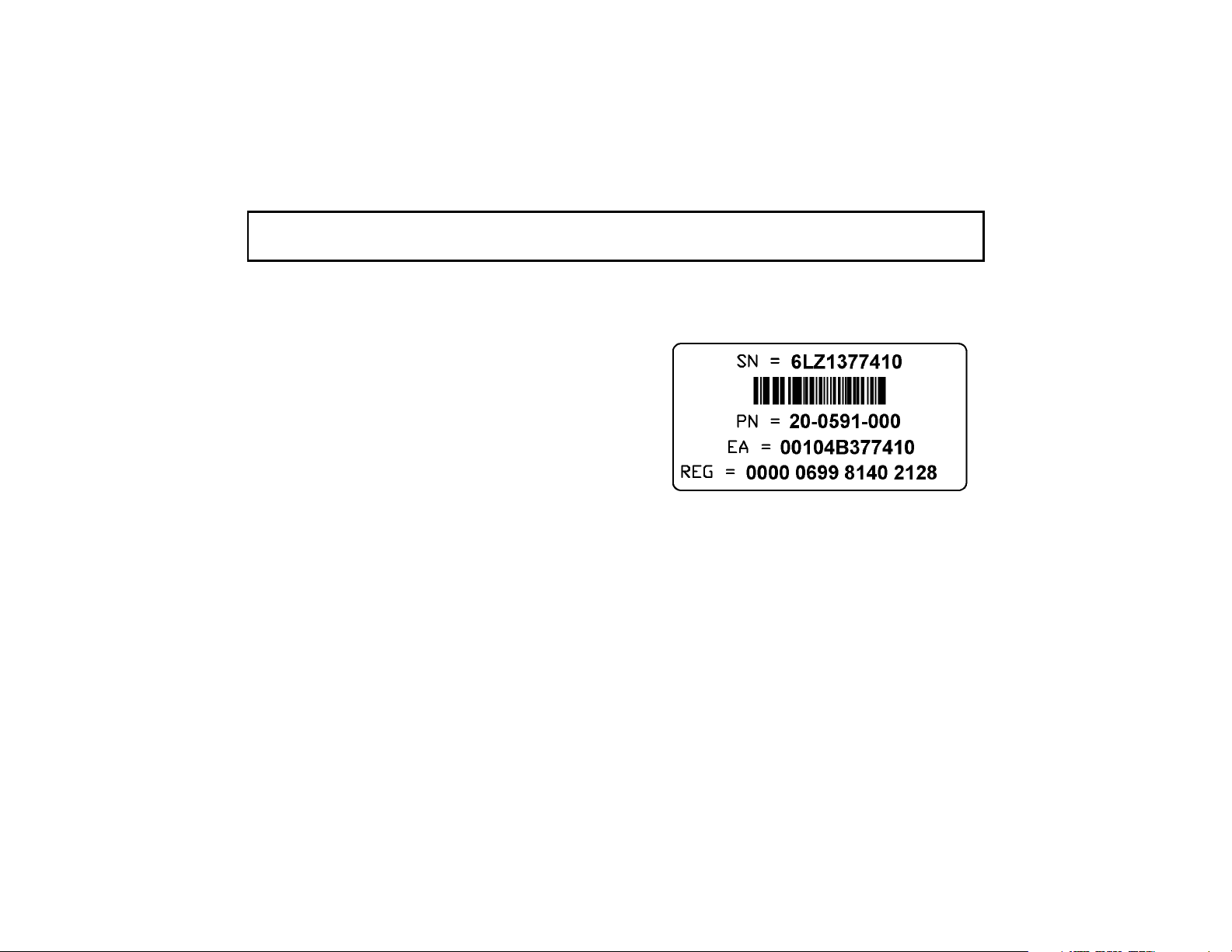
• The modem’s Media Access Control
(MAC) address (located on a bar code
sticker on the back of the modem). The
MAC address consists of 12 characters
preceded by the text EA =. In the
following example label image, the
MAC address is 00104B377410. Write
the MAC address in the blank provided
below.
• The modem’s model number (located
on a sticker on the bottom of the
modem). Your modem’s model number
will be 2940 or 2941.
MAC address: EA = __________________
Model number (circle one): 2940 or 2941
3
Page 7

B
EFORE YOU BEGIN
You should now contact your local cable
company and verify the following:
• You have cable service to your home
that supports two-way cable modem
access. If your cable company does not
provide two-way service, the
U.S. Robotics Cable Modem CMX will
not be able to communicate with your
cable company’s Internet access service.
You should immediately consult your
cable company and place of purchase to
determine the proper U.S. Robotics
cable modem that will work with your
cable company. You can also visit the
following URL for additional
information:
http://www.3com.com/cablemodem
• Your cable company has set up your
cable Internet access account. Your
cable company will establish an Internet
4
access account that will allow you to
send and receive e-mail, access the
World Wide Web, and receive other
Internet services. This account must be
established before you can use your
cable modem.
• You have a cable line near your PC
and it has been prepared for cable
modem service. If you do not have a
cable line in your home that supports
two-way cable modem access or if your
current cable connection is not
conveniently located near your
computer, your cable company can
install one. If you use your cable line for
cable television access, your cable
company can also install an additional
line for use with your cable modem.
Page 8
B
EFORE YOU BEGIN
Preparing Your Workspace
• Position your computer so that it is
located near your cable outlet.
• The cable modem should be located near
your computer and the cable outlet.
There should be plenty of room to guide
the cables away from the modem without
crimping the cables.
• The modem should be located where it
has ample space to allow constant
airflow around the unit.
• Do not stack anything on top of the cable
modem. (See the instructions on page 13
concerning stacking this modem with
3Com OfficeConnect products.)
• The temperature in the room where the
cable modem will be operating should be
between 0 and 40°C (32 and 104°F).
Relative humidity should be between 5
and 95%, non-condensing.
• Familiarize yourself with all of the
materials in this box. Please read these
installation instructions thoroughly
before installing your cable modem.
CAUTION:
Your cable company
will provide a cable connection. Do not
attempt any rewiring without first
contacting your cable company.
You Will Need These Items
Included:
• Cable modem
• Cable modem power supply
• RJ-45 network cable
• Rubber feet and stacking clips kit
• Cable Connections
CD-ROM
5
Page 9

B
EFORE YOU BEGIN
• Fold-out Quick Installation Guide
• This User’s Guide & Reference
Not Included:
• A PC running Windows 95 (or later)
or a Macintosh running System 7.5 (or
later) with TCP/IP protocol installed
(see the following two sections for more
information on installing TCP/IP)
• An active two-way cable line
• An active Ethernet port or network
interface card (NIC) installed in your
computer
• A 7/16 inch (or adjustable) wrench for
securing the cable line to the modem
• A screwdriver, pushpins, and screws (for
optional wall-mounting) The screw
heads should be at least 0.2” (5mm) in
diameter for them to be properly
captured in the slot. If you are using
wood screws, use #6 pan heads or
equivalent.
Configuring the TCP/IP
Protocol on a Windows PC
If you have a PC running Windows 95 or
later, you need to make sure the TCP/IP
communications protocol is installed on
your system before you install your cable
modem. The listing of actual components
installed on your PC depends on the
hardware installed in your computer. The
installation example in this guide assumes a
3Com EtherLink III 3C509B-TPO NIC
has been installed and the screen images
shown below reflect this hardware
configuration. Other networking cards will
work but the screen images will look
somewhat different.
6
Page 10
B
EFORE YOU BEGIN
NOTE:
If you need to install a
network interface card to give your
computer Ethernet capability but have
not yet done so, perform this operation
first by consulting your NIC installation
manual and then return here to
complete installation of the TCP/IP
software.
1.
Click Start, point to Settings, and then
click Control Panel.
2.
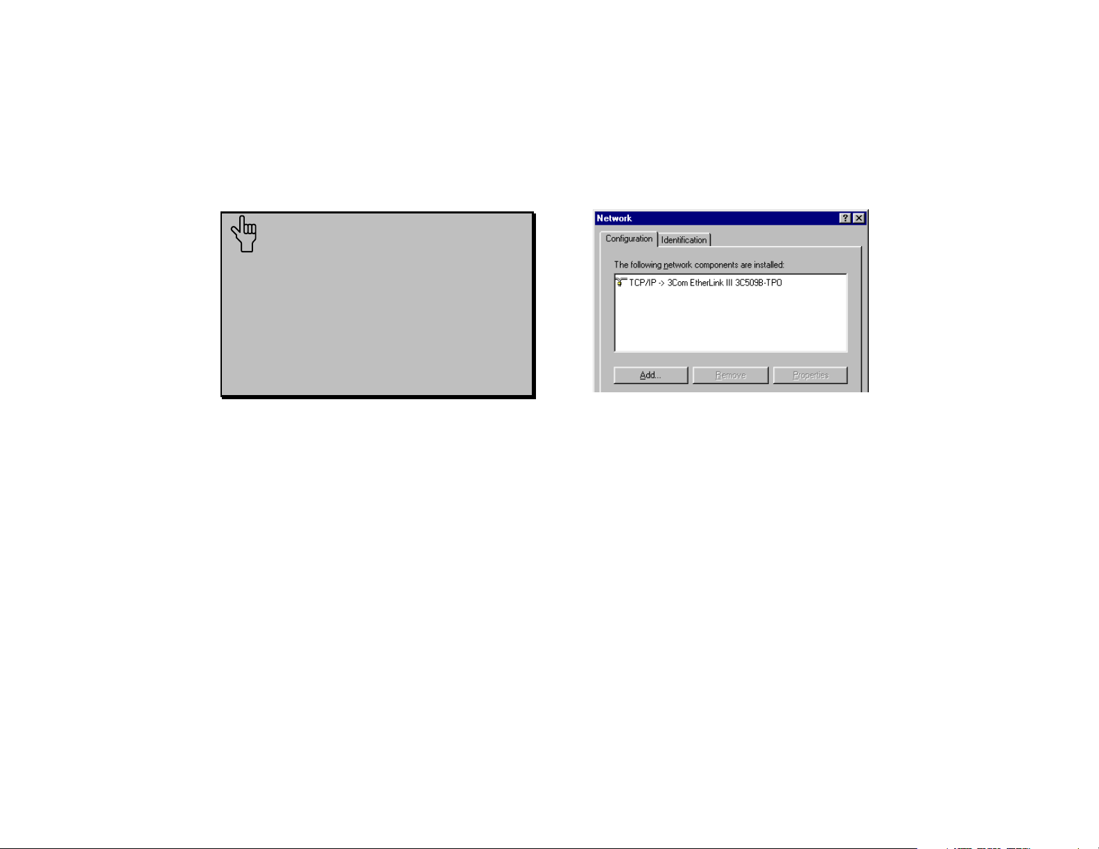
Double-click the Network icon.
3.
A list of installed network components
appears. Look for an entry that includes
TCP/IP -> followed by the NIC
hardware device installed in your
computer. (The entry for the 3C509BTPO example is shown in the following
screen image).
If an entry similar to this is present, go to
step 9 on the next page.
4.
If a similar entry is not present, click
Add...
5.
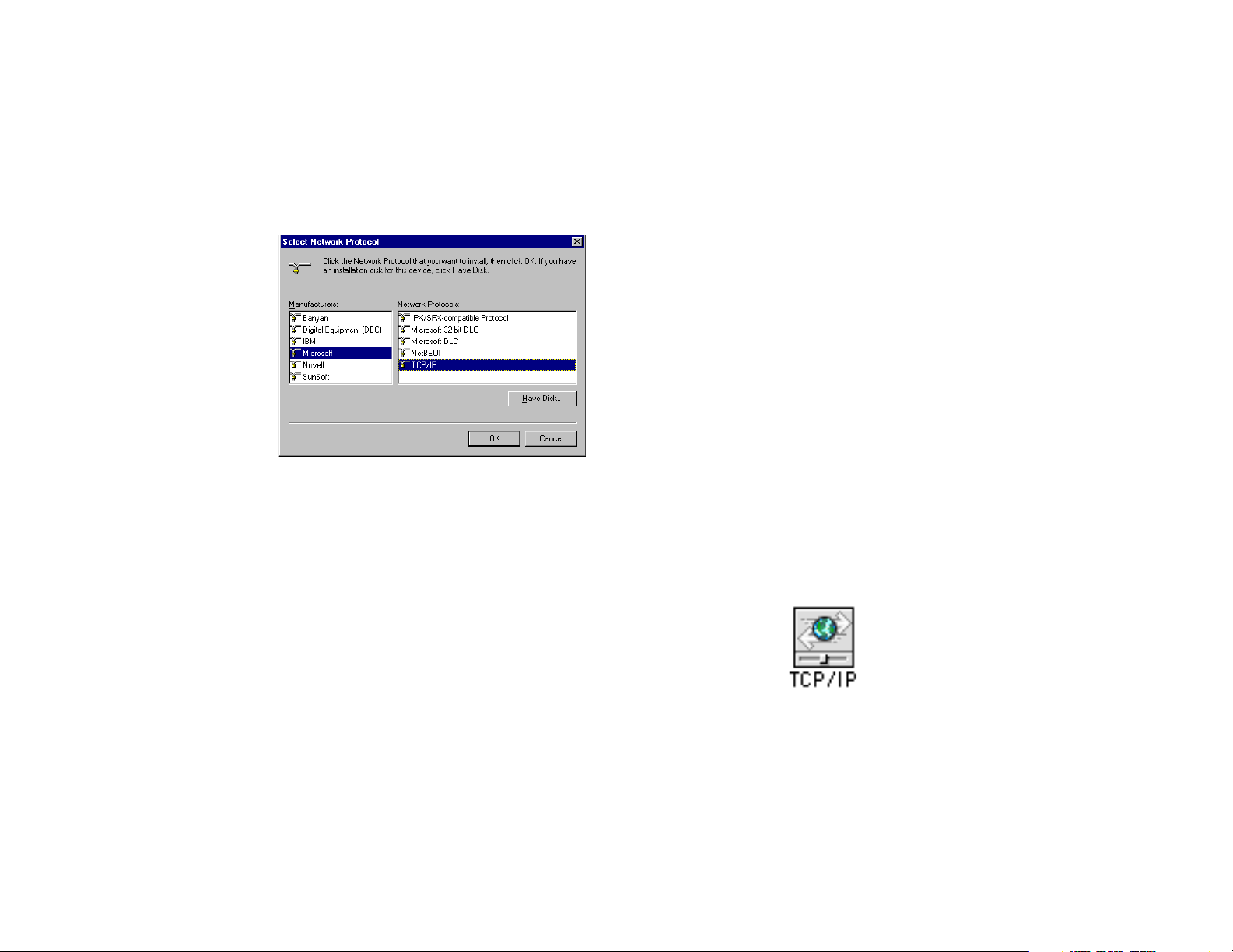
Click Protocol, and then click Add...
6.
Click Microsoft in the “Manufacturers:”
list and then click TCP/IP in the
“Network Protocols:” list. Click OK.
7
Page 11
7.
“TCP/IP” will appear in the list of
installed network components. Click
OK.
8.
Windows will now ask you if you would
like to restart your computer. Click No.
9.
Your cable company may provide you
with additional TCP/IP setup
instructions. Consult those instructions,
if provided, to complete configuration of
B
EFORE YOU BEGIN
your PC to work with your cable
modem. When you are finished, turn to
“Hardware and Software Installation”
(page 11).
Configuring the TCP/IP
Protocol on a Macintosh PC
You will need to configure TCP/IP to work
with your cable modem if you are using a
Macintosh.
1.
Double-click your System folder.
2.
Double-click Control Panels.
3.
Look for the TCP/IP Control Panel
icon.
8
Page 12

If you do not see this icon, you must
reinstall your Macintosh system
software and add networking support.
Consult your Macintosh User Manual
for more information on how to do this.
4.
Exit out of all open windows.
5.
Your cable company may provide you
with additional TCP/IP setup
instructions. Consult those instructions,
if provided, to complete configuration
of your Mac to work with your cable
modem. When you are finished, turn to
“Hardware and Software Installation”
(page 11).
B
EFORE YOU BEGIN
9
Page 13

B
EFORE YOU BEGIN
10
Page 14

ARDWARE AND SOFTWARE INSTALLATION
H
NOTE:
modem, write its serial number in the
space provided on the first page of this
manual. (You’ll find the serial number
above the bar code on the white sticker
on the back of the modem and on the
outside of the modem’s box.) If you
ever call our customer support
department, a representative will ask
you for the serial number. This will
help to identify your modem.
Before you begin installing the cable
modem hardware, you need to determine
how you want to incorporate the modem
into your work environment. There are
three installation options:
Before installing your
Wall-mount installation (this page)
1.
Desktop installation (page 13)
2.
OfficeConnect stacking installation
3.
(page 13)
Wall-Mount Installation
Your cable modem is capable of being wallmounted, if you choose to do so. The
bottom panel of the cable modem has two
raised brackets with slots as shown in the
following illustration.
NOTE:
cable modem, follow the instructions in
the section “Connecting the Cable
Modem to Your Computer” (pages 15-
18). Then return to this point to
continue the process.
Before wall-mounting the
11
Page 15

H
ARDWARE AND SOFTWARE INSTALLATION
1. Remove the mounting template from the
Installation Guide.
mounting
holes
These slots fit over the heads of wallmounting screws to secure the modem to
the wall. A mounting template for marking
the location of the mounting screws is
included in the foldout Installation Guide
that accompanies this manual.
12
®
2. Place the mounting template against the
wall at the location chosen for the cable
modem. The template should be parallel
to and at least 20 inches (50 cm) from
the floor. Insert pushpins through the
template cross hairs into the wall to mark
the locations for the screws.
3. Secure the mounting screws into the
wall. Do not drive the screws flush to the
wall. The screw head should be at least
¼” (6 mm) away from the wall so it can
lock into the slots on the modem’s case.
4. Fit the slots in the brackets on the
modem’s underside over the screw heads
and let the modem slide down into
position.
Page 16

.
User's Guide & Reference
INSTRUCTIONS FOR WALL-MOUNTING THE CABLE MODEM
Wall-mounting Template
See other side for basic instructions.
For complete instructions, see the
20"
[ 50 cm ]
H
ARDWARE AND SOFTWARE INSTALLATION
Computer” (page 15). Otherwise, turn to
“Installing the Cable Connections
CD-ROM” on page 18.
®
Desktop Installation
If you plan to place your modem on a flat
surface, you can use the four self-adhesive
rubber feet included in your modem’s
package to prevent your modem from
sliding around. Stick the feet to the marked
areas at each corner of the underside of your
modem. Turn to “Connecting the Cable
Modem to Your Computer” (page 15).
OfficeConnect Stacking
Installation
If you have not already done so, turn to
“Connecting the Cable Modem to Your
If you own 3Com OfficeConnect products,
you can use the four stacking clips included
in your modem’s package to neatly and
13
Page 17

H
ARDWARE AND SOFTWARE INSTALLATION
securely stack your cable modem with the
OfficeConnect unit(s). If possible, your
cable modem should always be the top unit
in a stack with OfficeConnect products.
Small hubs are the only units that should be
clipped to the top of a cable modem. Follow
these instructions to clip your modem to an
OfficeConnect unit.
1. Place the OfficeConnect device you
want at the bottom of the stack on a flat
surface. The supplied blue clips fit in the
positions on the side of the unit as shown
in step 1 of the illustration on the next
page.
2. Position a clip over one of these holes
and push it in until it clicks into place, as
shown in step 2 of the illustration on the
next page. Repeat this for the other clip
position on the same side.
3. Keeping the front of the units aligned,
position the top-most OfficeConnect
device and rest the bottom of the device
on the clips' spikes, as shown in step 3 of
the illustration on the next page. Push
the clips firmly until they click into
place.
NOTE:
To remove a clip, hold the
units firmly with one hand and hook the
first finger of your other hand around
the back of the clip. Be careful not to
pull so hard that you break the clip.
4. Repeat these steps to secure the other
side.
5. Turn to “Connecting the Cable Modem
to Your Computer” (page 15).
14
Page 18

H
ARDWARE AND SOFTWARE INSTALLATION
Connecting the Cable Modem
to Your Computer
TIP:
label them or make a sketch of how
they are connected. This can be helpful
when you plug them back in later.
CAUTION:
electric shock, make sure your
computer and all peripheral devices are
turned off and unplugged from
electrical outlets.
Before you unplug any cords,
To avoid risk of
15
Page 19

H
ARDWARE AND SOFTWARE INSTALLATION
NOTE:
Refer to the diagram on the following page while following these steps.
1. Turn off your computer and unplug it from the electrical outlet.
2. Using the following illustration as a guide, make the following connections:
• Connect your cable line to the cable modem’s CATV cable connector. Be careful not to
bend the wire in the center of the cable line when you connect it to the cable modem.
After hand-tightening the CATV cable connector, use your 7/16 inch or adjustable wrench
to firmly tighten the connector. Be careful not to over-tighten the connector or you might
damage the connector or your cable modem.
• Plug the cable modem’s power supply into a wall socket or surge protector and into the
+
cable modem’s power jack (labeled with a graphic that looks like this:
-
).
• Plug one end of the RJ-45 network cable into the cable modem’s RJ-45 jack and the other
end into the existing network interface card installed in your computer.
• The serial port on your cable modem is unused during two-way operation. If the cable
modem is being used with an analog modem for telephony-return cable modem operation,
you will receive additional instructions on how to make these connections.
3. Verify that your cable modem starts up and initializes properly. You can tell that your
modem is operating properly if the Cable Modem Power and Cable Modem Status LEDs
16
Page 20

H
ARDWARE AND SOFTWARE INSTALLATION
are lighted solid green. If you are powering up your cable modem for the first time, allow 5
to 15 minutes for this process to complete. Consult the chapter titled “Cable Modem
Operation” for a more in-depth description of the front panel LED indicators.
SERIAL
CATV
10 BT
power supply
(to wall outlet)
cable line (to cable
outlet)
RJ-45 cable
RJ-45 Cable
(to NIC)
4. Plug the computer’s power cord back into the computer. Turn on the computer. When
installation is complete, your setup should resemble the following diagram.
17
Page 21

H
ARDWARE AND SOFTWARE INSTALLATION
RJ-45 cable
(to NIC)
Cable
Modem
power supply cable
Power
(to wall outlet)
cable outlet
212
13
311
410
59
68
7
2585
15
3080
4575
5070
5565
60
CMX
3
Com U.S. Robotics
Cable Modem
Cable
PCLink
FCN
Activity
Activity
Status
Status
Installing the Cable
Connections
CD-ROM
Although you do not need to install the included Cable Connections CD-ROM to use your
Cable Modem CMX, you will want to discover the valuable free software products and Internet
service provider offers included on the CD-ROM. To install Cable Connections, follow the
instructions inside the CD’s jacket or on the CD-ROM itself.
18
Page 22

ABLE
C
ODEM OPERATION
M
Once your cable modem is properly installed and power supply is connected to AC power, it
will automatically scan for the active cable modem channel from your cable company’s server.
Once the front panel LEDs indicate the modem is connected to the server, all you need to do is
launch your Internet or e-mail software and you’re ready to work online.
Here’s a quick overview of the LED lights on the front panel of your modem and what they can
tell you about the performance of your modem and the condition of your connection.
Power
Cable
Modem
1
Status
Cable Modem
CMX
3
Com U.S. Robotics
Cable
PC Link
Activity
Status
4
3
2
Activity
FCN
6
5
19
Page 23

C
ABLE MODEM OPERATION
1. Cable Modem Power - Indicates power is applied to the cable modem. This light is solid
green when the modem is on.
2. Cable Modem Status - This LED varies in color (orange and green) and indicates the
modem’s status as described in the following chart:
LED STATE
SHORT OFF, LONG ORANGE
ORANGE
SHORT OFF, SHORT ORANGE
LONG ORANGE, SHORT GREEN
SHORT OFF, SHORT GREEN
GREEN
REPEATING
YES
NO
YES
YES
YES
NO
DESCRIPTION
Startup, power on self test
Failed power on self test
Downstream hunt
Acquisition in process
Offline/not authorized for service
Fully operational state
3. PC Link Status - Indicates that the cable modem is connected to the Ethernet card in your
computer. This light is solid green when this link is established and your computer is turned
on.
4. PC Link Activity - Indicates that data is being transmitted to or from your PC over the
Ethernet port. Flashing orange indicates traffic. This LED should blink when data is being
transmitted or received over the Ethernet port.
20
Page 24

C
ABLE MODEM OPERATION
5. Cable Activity - Indicates that data is being transmitted to or from your cable company over
the RF (cable) port. Flashing orange indicates traffic.
6. FCN - Individual cable operators determine the function of this LED.
21
Page 25

C
ABLE MODEM OPERATION
22
Page 26

ROUBLESHOOTING AND SUPPORT RESOURCES
T
PROBLEM
I cannot access my
email or Internet
service.
The Cable Status
LED never stops
blinking.
POSSIBLE SOLUTION
1. Check all connections. Make sure the cable line is securely connected to
the cable jack on the back of the modem. Verify that the RJ 45 cable is
securely plugged into both the modem and your network interface card.
Make sure your power supply is properly plugged into both the modem
and a wall outlet or surge protector. If your cable modem is properly
connected, the “Cable Modem Power”, “Cable Modem Status”, and
“PC Link Status” indicator lights on the front of the modem should all
be a solid color.
2. Call your cable service provider to verify that their service is two-way.
This modem is designed for use with two-way cable plants.
3. Your network interface card may be malfunctioning. Refer to its
documentation for troubleshooting information.
4. You may not have installed TCP/IP properly or the TCP/IP parameters
provided by your cable company may not be correct for your computer.
The signal from your cable company’s equipment may be too weak or the
cable line may not be properly attached to the modem. If the cable line is
properly connected to the modem, call your cable company to verify
whether or not a weak signal may be the problem.
23
Page 27

T
ROUBLESHOOTING AND SUPPORT RESOURCES
PROBLEM
All of LEDs on the
front of my modem
look right, but I
still can’t access
the Internet.
The power on my
modem goes on
and off
sporadically. The
Cable Modem
Status light never
stops blinking.
POSSIBLE SOLUTION
1. If the Cable Modem Power, Cable Modem Status, and PC Link Status
LEDs are on but not blinking, your cable modem is operating properly.
Try shutting down and powering off your computer and then turning it
back on. This will cause your computer to re-establish
communications with your cable company’s computer.
2. You may not have installed TCP/IP properly or the TCP/IP parameters
provided by your cable company may not be correct for your computer.
You may be using the wrong power supply. Check that the power supply
you are using is the one that came with your cable modem.
24
Page 28

T
ROUBLESHOOTING AND SUPPORT RESOURCES
Support Resources
3
Com BBS
Dial the 3Com BBS, 847-262-6000, using
the communications software of your
choice.
Internet FTP
Our ftp site provides a free library
containing the same files as the BBS site.
FTP to ftp.usr.com.
Internet on Demand
Our Internet on Demand site provides
automated technical support through a
library containing product information,
quick reference cards, and installation
help. To obtain an index of available
documents, send a blank e-mail to
support@usr.com. To have a document
e-mailed to you, send the document's number
as the subject.
World Wide Web
The 3Com home page contains the same
information as the Internet on Demand
listing. Log on to http://support.3com.com
CompuServe
You can access the same information as the
Internet FTP site through CompuServe. The
forum address is GO THREECOM.
Address private messages to 76711,707.
America Online
Go to the Keyword field and type 3COM to
connect to various 3Com resources, such as
file libraries, message boards, online
customer support, and product
announcements.
25
Page 29

T
ROUBLESHOOTING AND SUPPORT RESOURCES
90-Day Free Installation Support
3Com offers free 90 day installation
support for this product. Please call the
following toll-free number.
90-Day Free Installation Support
888-877-5040
After the 90 day limit, refer to our payper-call options below.
Technical Support Hotline
Technical questions about 3Com
U.S. Robotics modems can also be
answered by technical support
representatives. The hotline is a toll call.
Hotline 847-262-2550
(Hours: 8:00 am - 6:00 pm CST)
If You Are Still Having
Problems
• Review this manual.
• Call or visit your modem dealer. They
may be able to assist you.
• If your dealer can't help you, contact
3Com Customer Support. When you call,
specify your modem’s serial number
(found on the modem and on the outside
of the box) and the software being used.
If You Need to Return the
Modem to Us
Contact 3Com Customer Support. If the
support representative determines that you
need to return the modem, you will receive an
SRO (Service Repair Order) number. You
must have an SRO number before returning
26
Page 30

T
ROUBLESHOOTING AND SUPPORT RESOURCES
the modem to us. Ship the unit, postage
paid, in a strong box made of corrugated
cardboard with plenty of packing material.
DO NOT send the modem back in the
original box. Send ONLY the modem
(NOT manuals, diskettes, etc.). Include
your SRO number, name, and address on
the shipping label as well as inside the
package. If possible, send the package via
a courier capable of tracking the progress
of the shipment. Ship to the following
address:
3
Com
SRO #________
attn: Dock 15 PCD
1800 W. Central Ave.
Mount Prospect, IL 60056
27
Page 31

T
ROUBLESHOOTING AND SUPPORT RESOURCES
28
Page 32

EGULATORY INFORMATION AND LIMITED
R
ARRANTY
W
Manufacturer’s Declaration of
Conformity
3Com
3800 Golf Road
Rolling Meadows, IL 60008
U.S.A.
declares that the product U.S. Robotics
Cable Modem CMX conforms to the FCC’s
specifications:
Part 15:
Operation is subject to the following two
conditions:
(1) this device may not cause harmful
electromagnetic interference, and
(2) this device must accept any interference
received including interference that may
cause undesired operations.
Caution to the User
The user is cautioned that any changes or
modifications not expressly approved by the
party responsible for compliance could void
the user’s authority to operate the
equipment.
Performance Specifications
This equipment has a bit-error rate (BER)
less than 10-8 when the signal-to-noise ratio
(SNR) is 23.5 dB or greater when operating
in 64 QAM mode, and when the SNR is
30.0 dB or greater when operating in 256
QAM mode.
29
Page 33

R
EGULATORY INFORMATION AND LIMITED WARRANTY
Export Notices
• Unlawful to export from the US or
Canada without an approved US
Department of Commerce export
license.
• The hardware contained in this product
contains encryption software which may
not be exported or transferred from the
US or Canada without an approved US
Department of Commerce export
license.
License Agreement
You agree that you will not export or reexport the Software or accompanying
documentation (or any copies thereof) or
any products utilizing the Software or such
documentation in violation of any
applicable laws or regulations of the United
30
States or the country in which you obtained
them.
The software covered by this agreement
may contain strong data encryption code
that cannot be exported outside of the U.S.
or Canada. You agree that you will not
export/reexport, either physically or
electronically, the encryption software or
accompanying documentation (or copies
thereof) or any products utilizing the
encryption software or such documentation
without obtaining written authorization
from the U.S. Department of Commerce.
Industry Canada (IC)
This digital apparatus does not exceed the
Class B limits for radio noise emissions
from digital apparatus set out in the
interference-causing equipment standard
entitled Digital Apparatus, ICES-003 of
Industry Canada.
Page 34

R
EGULATORY INFORMATION AND LIMITED WARRANTY
Cet appareil numérique respecte les limites
de bruits radioélectriques applicables aux
appareils numériques de Classe B préscrites
dans la norme sur le matériel brouilleur:
Appareils Numériques, NMB-003 édictée
par l'Industrie Canada.
UL Listing/CUL Listing
This information technology equipment is
UL-Listed and CUL-Listed for use with
UL-Listed personal computers that have
installation instructions detailing user
installation of card cage accessories.
Radio and Television Interference
This equipment generates and uses radio
frequency energy and if not installed and
used properly, in strict accordance with the
manufacturer’s instructions, may cause
interference to radio and television
reception. This device has been tested and
found to comply with the limits for a Class
B computing device in accordance with the
specifications in Part 15 of FCC rules,
which are designed to provide reasonable
protection against such interference in a
residential installation.
However, there is no guarantee that
interference will not occur in a particular
installation. If this device does cause
interference to radio or television reception,
which you can determine by monitoring
reception when the modem is installed and
when it is removed from the computer, try
to correct the problem with one or more of
the following measures:
• Reorient the receiving antenna (for
televisions with antenna reception only)
or cable input device.
• Relocate the computer with respect to
the receiver.
31
Page 35

R
EGULATORY INFORMATION AND LIMITED WARRANTY
• Relocate the computer and/or the
receiver so that they are on separate
branch circuits.
If necessary, consult your dealer or an
experienced radio/television technician for
additional suggestions. You may find the
following booklet, prepared by the Federal
Communications Commission, helpful:
How to Identify and Resolve RadioTV Interference Problems
Stock No. 004-000-0345-4
U.S. Government Printing Office
Washington, DC 20402
In accordance with Part 15 of the FCC
rules, the user is cautioned that any changes
or modifications to the equipment described
in this manual that are not expressly
approved by 3Com could void the user’s
authority to operate the equipment.
3
Com Corporation Limited
Warranty
3Com warrants this hardware product to be
free from defects in workmanship and
materials, under normal use and service, for
the following length of time from the date
of purchase from 3Com or its authorized
reseller: 5 years. 3Com’s sole obligation
under this express warranty shall be, at
3Com’s option and expense, to repair the
defective product or part, deliver to
Customer an equivalent product or part to
replace the defective item, or if neither of
the two foregoing options is reasonably
available, 3Com may, in its sole discretion,
refund to Customer the purchase price paid
for the defective product. All products that
are replaced will become the property of
3Com. Replacement products may be new
32
Page 36

R
EGULATORY INFORMATION AND LIMITED WARRANTY
or reconditioned. 3Com warrants any
replaced or repaired product or part for
ninety (90) days from shipment, or the
remainder of the initial warranty period,
whichever is longer.
YEAR 2000 WARRANTY: In addition to
the Hardware Warranty stated above, 3Com
warrants that each product sold or licensed
to Customer on and after January 1, 1998
that is date sensitive will continue
performing properly with regard to such
date data on and after January 1, 2000,
provided that all other products used by
Customer in connection or combination
with the 3Com product, including
hardware, software, and firmware,
accurately exchange date data with the
3Com product, with the exception of those
products identified at 3Com’s Web site,
http://www.3com.com/products/yr2000.html
as not meeting this standard. If it appears
that any product that is stated to meet this
standard does not perform properly with
regard to such date data on and after
January 1, 2000, and Customer notifies
3Com before the later of April 1, 2000, or
ninety (90) days after purchase of the
product from 3Com or its authorized
reseller, 3Com shall, at its option and
expense, provide a software update which
would effect the proper performance of
such product, repair such product, deliver to
Customer an equivalent product to replace
such product, or if none of the foregoing is
feasible, refund to Customer the purchase
price paid for such product.
Any software update or replaced or repaired
product will carry a Year 2000 Warranty for
ninety (90) days after purchase or until
April 1, 2000, whichever is later.
33
Page 37

R
EGULATORY INFORMATION AND LIMITED WARRANTY
OBTAINING WARRANTY SERVICE:
Customer must contact a 3Com Corporate
Service Center or an Authorized 3Com
Service Center within the applicable
warranty period to obtain warranty service
authorization. Dated proof of purchase from
3Com or its authorized reseller may be
required. Products returned to 3Com's
Corporate Service Center must be preauthorized by 3Com with a Service Return
Order (SRO) number marked on the outside
of the package, and sent prepaid and
packaged appropriately for safe shipment,
and it is recommended that they be insured
or sent by a method that provides for
tracking of the package. The repaired or
replaced item will be shipped to Customer,
at 3Com's expense, not later than thirty (30)
days after 3Com receives the defective
product.
Dead- or Defective-on-Arrival. In the event
a product completely fails to function or
exhibits a defect in materials or
workmanship within the first forty-eight
(48) hours of installation but no later than
thirty (30) days after the date of purchase,
and this is verified by 3Com, it will be
considered dead- or defective-on-arrival
(DOA) and a replacement shall be provided
by advance replacement. The replacement
product will normally be shipped not later
than three (3) business days after 3Com’s
verification of the DOA product, but may
be delayed due to export or import
procedures. When an advance replacement
is provided and Customer fails to return the
original product to 3Com within fifteen (15)
days after shipment of the replacement,
3Com will charge Customer for the
replacement product, at list price.
34
Page 38

R
EGULATORY INFORMATION AND LIMITED WARRANTY
3Com shall not be responsible for any
software, firmware, information, or memory
data of Customer contained in, stored on, or
integrated with any products returned to
3Com for repair, whether under warranty or
not.
WARRANTIES EXCLUSIVE: IF A
3COM PRODUCT DOES NOT OPERATE
AS WARRANTED ABOVE,
CUSTOMER'S SOLE REMEDY FOR
BREACH OF THAT WARRANTY
SHALL BE REPAIR, REPLACEMENT,
OR REFUND OF THE PURCHASE
PRICE PAID, AT 3COM'S OPTION. TO
THE FULL EXTENT ALLOWED BY
LAW, THE FOREGOING WARRANTIES
AND REMEDIES ARE EXCLUSIVE
AND ARE IN LIEU OF ALL OTHER
WARRANTIES, TERMS, OR
CONDITIONS, EXPRESS OR IMPLIED,
EITHER IN FACT OR BY OPERATION
OF LAW, STATUTORY OR
OTHERWISE, INCLUDING
WARRANTIES, TERMS, OR
CONDITIONS OF MERCHANTABILITY,
FITNESS FOR A PARTICULAR
PURPOSE, SATISFACTORY QUALITY,
CORRESPONDENCE WITH
DESCRIPTION, AND NONINFRINGEMENT, ALL OF WHICH ARE
EXPRESSLY DISCLAIMED. 3COM
NEITHER ASSUMES NOR
AUTHORIZES ANY OTHER PERSON
TO ASSUME FOR IT ANY OTHER
LIABILITY IN CONNECTION WITH
THE SALE, INSTALLATION,
MAINTENANCE OR USE OF ITS
PRODUCTS.
3COM SHALL NOT BE LIABLE UNDER
THIS WARRANTY IF ITS TESTING
35
Page 39

R
EGULATORY INFORMATION AND LIMITED WARRANTY
AND EXAMINATION DISCLOSE THAT
THE ALLEGED DEFECT OR
MALFUNCTION IN THE PRODUCT
DOES NOT EXIST OR WAS CAUSED
BY CUSTOMER'S OR ANY THIRD
PERSON'S MISUSE, NEGLECT,
IMPROPER INSTALLATION OR
TESTING, UNAUTHORIZED
ATTEMPTS TO OPEN, REPAIR OR
MODIFY THE PRODUCT, OR ANY
OTHER CAUSE BEYOND THE RANGE
OF THE INTENDED USE, OR BY
ACCIDENT, FIRE, LIGHTNING, OTHER
HAZARDS, OR ACTS OF GOD.
LIMITATION OF LIABILITY. TO THE
FULL EXTENT ALLOWED BY LAW,
3COM ALSO EXCLUDES FOR ITSELF
AND ITS SUPPLIERS ANY LIABILITY,
WHETHER BASED IN CONTRACT OR
TORT (INCLUDING NEGLIGENCE),
FOR INCIDENTAL, CONSEQUENTIAL,
INDIRECT, SPECIAL, OR PUNITIVE
DAMAGES OF ANY KIND, OR FOR
LOSS OF REVENUE OR PROFITS, LOSS
OF BUSINESS, LOSS OF
INFORMATION OR DATA, OR OTHER
FINANCIAL LOSS ARISING OUT OF OR
IN CONNECTION WITH THE SALE,
INSTALLATION, MAINTENANCE, USE,
PERFORMANCE, FAILURE, OR
INTERRUPTION OF ITS PRODUCTS,
EVEN IF 3COM OR ITS AUTHORIZED
RESELLER HAS BEEN ADVISED OF
THE POSSIBILITY OF SUCH
DAMAGES, AND LIMITS ITS
LIABILITY TO REPAIR,
REPLACEMENT, OR REFUND OF THE
PURCHASE PRICE PAID, AT 3COM'S
OPTION. THIS DISCLAIMER OF
LIABILITY FOR DAMAGES WILL NOT
BE AFFECTED IF ANY REMEDY
36
Page 40

R
EGULATORY INFORMATION AND LIMITED WARRANTY
PROVIDED HEREIN SHALL FAIL OF
ITS ESSENTIAL PURPOSE.
DISCLAIMER: Some countries, states, or
provinces do not allow the exclusion or
limitation of implied warranties or the
limitation of incidental or consequential
damages for certain products supplied to
consumers, or the limitation of liability for
personal injury, so the above limitations and
exclusions may be limited in their
application to you. When the implied
warranties are not allowed to be excluded in
their entirety, they will be limited to the
duration of the applicable written warranty.
This warranty gives you specific legal rights
which may vary depending on local law.
GOVERNING LAW: This Limited
Warranty shall be governed by the laws of
the State of California, U.S.A. excluding its
conflicts of laws principles and excluding
the United Nations Convention on
Contracts for the International Sale of
Goods.
37
 Loading...