

Page 1
3B SCIENTIFIC
Microwave Set 9.4 GHz (230 V, 50/60 Hz)
Microwave Set 10.5 GHz (115 V, 50/60 Hz)
1009951 / U8493600-230
1009950 / U8493600-115
Instruction sheet
08/11 ERL/ALF
®
PHYSICS
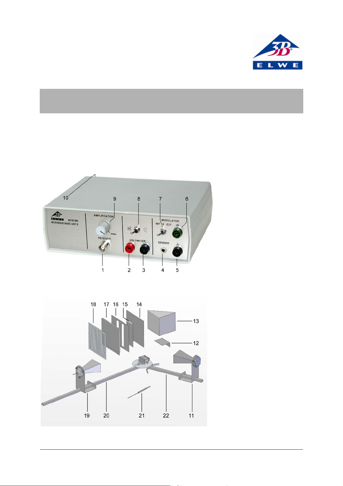
Control unit
1 Receiver terminal
2 Amplifier output
3 Amplifier output (ground)
4 Transmitter terminal
5 Modulation input (ground)
6 Modulation input
7 Modulator selector switch (inter-
nal/off/external),
8 Switch for internal speaker
9 Controller for receiver signal
amplification
10 Socket for 12-V AC plug-in power
supply (rear of case)
Accessories
11 Transmitter with horn antenna
12 Stand for prism
13 Paraffin prism
14 Reflection plate
15 Cover plate for double slit
16 Plate with double slit
17 Absorption plate
18 Polarisation grating
19 Receiver with horn antenna
20 Microwave bench
21 Microwave probe
22 Folding microwave bench with
plate holder
1
Page 2

1. Safety instructions
High frequency radio waves can penetrate biological
tissues and cause them to heat up. The microwave
transmitter included here is sufficiently low-powered
that the hazards are negligible when it is used correctly.
Safe operation of the equipment is guaranteed, provided it is used correctly. However, there is no guarantee of safety if the equipment is used in an improper or careless manner.
• Before setting up or starting any experiments,
check the housing and mains lead for any damage.
• If it is deemed that the equipment can no longer
be operated without risk (e.g. visible damage has
occurred), the equipment should be switched off
immediately and secured against any inadvertent use.
• The transmitter is only permitted to be con-
nected to 3B-ELWE control unit.
• In schools and educational establishments, the
equipment may only be operated under the supervision of trained personnel.
• Avoid looking directly into the antenna horn of
the transmitter or the reflected beam.
• Only trained electricians are permitted to open
up the apparatus’ housing.
2. Description
This apparatus allows microwaves to be transmitted
and received.
The components and equipment included allow for
various experiments to be performed. These can
achieve both qualitative and quantitative results.
A narrow beam of electro-magnetic waves with wavelength in the cm range can be output by a transmitter and picked up using the horn antenna (19) or the
sensor probe (21). The modulation of the receiver
signal can be rendered audible by means of an internal speaker, in which case the loudness of the
acoustic signal varies with the intensity of the received signal.
The microwave apparatus is powered via a 12-V AC
plug-in power supply.
The microwave apparatus 10.5 GHz (1009950) is for
operation with a mains voltage of 115 V (±10 %), and
the microwave apparatus 9.4 GHz (1009951) is for
operation with a mains voltage of 230 V (±10 %).
3. Contents
1 Control unit
1 Transmitter with horn antenna
1 Receiver with horn antenna
1 Microwave probe
1 Mikrowave bench, 800 mm
1 Microwave bench, 400 mm with plate holder
1 Reflection plate 180 x 180 mm²
1 Polarisation grating, 180 x 180 mm²
1 Absorption plate, fibreboard, 180 x 180 mm²
1 Paraffin prism
1 Stand for prism
1 Plate with double slit
1 Cover plate for double slit
1 Instruction sheet
4. Technical data
Transmitter with horn antenna:
Frequency of oscillator: 9,5 GHz (1009951)
10,5 GHz (1009950)
Transmitted power: 10 mW to 25 mW
Modulation type: AM
Modulation signal: Selector switch
Internal/off/external
Internal modulation: 3kHz approx.
80% AM approx.
External modulation: 100 Hz to 20 kHz,
max. 1 V
Acoustic signal: internal (switchable)
Output voltage: 10 V max.
Receiver with horn antenna: Silicon diode with
resonator
Microwave probe: Silicon diode with
resonator
Supply voltage: 12 V AC via plug-in
supply
Dimensions (control unit): 170 x 200 x 75 mm
3
5. Operation
5.1 Set-up of base rails (basic set-up)
• Insert the central screw under the scale disc in
the hole in the long rail.
The default set-up is with the rails opened out in a
line (the arrow on the long rail points to “0°” on the
protractor scale.
• Move the articulated base so that the pointer
coincides with the zero point of the scale.
The pointer is aligned with the normal of the screen
holder and thus allows the angle of incidence to be
read off or adjusted directly (read off the outer numeric scale).
5.2 System set-up
• Connect to the mains.
• Connect the receiver with horn antenna or the
microwave probe to the receiver terminal (1).
• Connect the transmitter with horn antenna to
the transmitter terminal (4).
• Set up the transmitter and receiver on the base
rails as appropriate to the experiment.
• Set the controller for the signal gain of the
speaker (9) to its centre position.
• Use the switch (8) to turn on the speaker.
2
Page 3

• Use switch (7) to send the modulator to “INT”.
The microwave signal emitted is modulated with a
square wave. The modulation frequency can be listened to by means of the built-in speaker.
The amplified receiver signal can be output from
sockets (2) and (3) in the form of a DC signal (once
modulation has been turned off), in the form of a
square wave (with internal modulation) or in the
form of low frequency signal (external modulation).
Modulation is deactivated when switch (7) is in its
centre position. DC signals proportional to the level
and gain are output from sockets (3) and (4).
6. Sample experiments
6.1 Straight-line propagation of microwaves
• Set up the transmitter (11) and receiver (19)
facing one another.
• With the receiver off the rail, move it in a
plane perpendicular to the rail.
The optimum reception is when the horns are
directly facing one another.
Conclusion: microwaves propagate in a straight
line (in uniform media or in a vacuum).
6.2 Penetration
• Attach the dry absorption plate (14) (electrical
insulator) to the plate holder between the
transmitter and receiver.
• Set the amplification (9) to a medium level.
Conclusion: microwaves can penetrate insulators,
as demonstrated by the reception of a signal.
This can, for example, be displayed using an instrument with a dial (e.g. AM50 analog multimeter
1003073/U17450).
If switch (7) is set to “EXT” low frequency signals (e.g.
from an MP3 player) can be input to sockets (5) and
(6) and played on the internal speaker inside the
basic apparatus. (jack to 4-mm socket adapter needed).
Information is sent via the microwave signal from
the transmitter to the receiver.
6.3 Screening and absorption
• Place the reflection plate (14) (electrical con-
ductor) between the transmitter and receiver.
• Set the amplification to a low level.
Conclusion: electrical conductors can screen out
microwaves (metal plates),
as demonstrated by the
fact that no signal is received.
• Attach the absorption plate to the plate holder
having dampened both sides first.
Conclusion: When penetrating materials of low
conductivity, the microwaves are attenuated, i.e.
partially absorbed.
3
Page 4

6.4 Reflection
• Set up the basic configuration (5.1).
• Line up the reflector plate at angles of ap-
proximately 30°, 40°, 50° and 60° with the
help of the pointer for the rails, which points
in the direction of the normal (a line perpendicular to the mirror’s surface).
• Change the angle of the long rail until the
maximum reception is attained.
• Measure angles of incidence from the normal
(arrow).
Conclusion: an electrical conductor reflects microwaves. This confirms the law of reflection.
6.5 Determining wavelength of standing waves
• Set up the transmitter and reflector plate fac-
ing each other about 50 cm apart (angle of incidence 0°).
The transmitted and reflected waves are superimposed, resulting in a standing wave.
• Using the microwave probe (21) (with the
marking on the special probe facing upwards)
determine the distance a between two adjacent minima (this corresponds to half the
wavelength).
• Calculate the frequency f = c/λ from the wave-
length λ of the microwaves.
λ
≈
Results: a =
1,6 cm, ≈f 9,4 GHz
2
6.6 Refraction
• Set up the basic configuration (5.1).
• Insert the stand provided for the prism (12)
into the side facing away from the arrow.
• Put the prism (13) onto the stand and line it
up.
• Turn the long rail until the maximum recep-
tion is attained.
Conclusion: microwaves penetrate paraffin. As the
waves pass from air to paraffin and from paraffin
to air, the speed of propagation is altered and thus
so is the direction (refraction).
4
Page 5

6.7 Huygens’ principle
• Set up the transmitter (11) about 20 cm from
the plate holder and the receiver (19) about 80
cm behind the late holder on the rails.
• Turn the receiver around on its rail so that it is
out of the bundled microwave beam and the
signal is clearly weakened.
• Insert a single slit aperture into the plate
holder and secure it gently in place (line up the
centre of the slit in the centre of the plate).
Conclusion: microwaves are diffracted by the slit
and wavelets can be detected beyond the plate (the
modulation signal is audibly louder).
6.8 Diffraction
• Clamp the cover plate (15) in the holder on the
hinge plate.
• Set up the transmitter about 20 cm in front of
the plate.
• Move the probe (21) in a horizontal plane be-
hind the plate.
Conclusion: even when the probe is in the shadow
of the plate, it can still pick up signals due to diffraction.
6.9 Interference
• Clamp the plate with the double slit (16) cen-
trally in the holder on the plate over the hinge.
• Position the transmitter about 12 cm in front
of the plate.
• Move the receiver probe parallel to the plate
with the double slit about 6 cm behind it.
Conclusion: Since the number of maxima is larger
than the number of slits, this demonstrates the
presence of interference.
5
Page 6

6.10 Polarisation
• Set up the polarisation grating (18) in the
screen holder.
• Check the reception when the polarisation
grating is aligned horizontally.
• Check the reception when the polarisation
grating is aligned vertically.
Conclusion: Since in one state a signal is received
but when the grating is rotated 90° no signal
reaches the receiver, it can be demonstrated that
the horn antenna produces a field that oscillates in
one direction only, i.e. the output is polarised.
The experiment proves that the waves are transverse.
If the transmitter and receiver are set up so that
one is vertical and one horizontal, no reception is
possible
If the polarisation grating introduced into the
beam and tilted by 45°, an attenuated signal is
received. The polarising plane is thus inclined.
6.11 Transmission of information
• Set up the transmitter and receiver facing one
another.
• With the receiver off the rail, move it in a
plane perpendicular to the rail.
• Reception is best when the openings are facing
one another.
Using internal modulation (3 kHz signal) or external modulation (e.g. sound from an MP3 player) it
is possible to transmit information.
Conclusion: microwaves (electro-magnetic waves)
can carry information.
Elwe Didactic GmbH ▪ Steinfelsstr. 5 ▪ 08248 Klingenthal ▪ Germany ▪ www.elwedidactic.com
3B Scientific GmbH ▪ Rudorffweg 8 ▪ 21031 Hamburg ▪ Germany ▪ www.3bscientific.com
Subject to technical amendments
© Copyright 2011 3B Scientific GmbH
 Loading...