

Page 1
3B SCIENTIFIC® PHYSICS
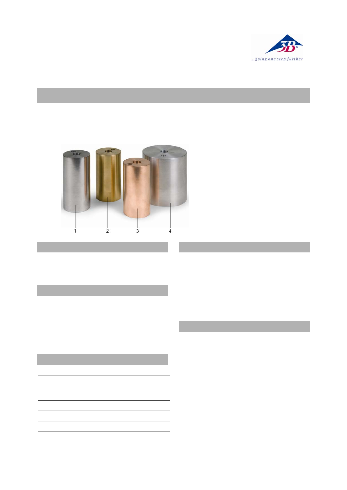
Satz 4 Kalorimeterzylinder U30070
Bedienungsanleitung
11/08 ALF
1 Kalorimeter, Stahl
2 Kalorimeter, Messing
3 Kalorimeter, Kupfer
4 Kalorimeter, Aluminium
1. Sicherheitshinweise
Verbrennungsgefahr durch Heizelement oder
Kalorimeter.
• Apparatur vor dem Abbau abkühlen lassen.
2. Beschreibung
Der Satz 4 Kalorimeterzylinder dient zur Bestimmung
der spezifischen Wärmekapazitäten von Aluminium,
Messing, Kupfer und Stahl.
Die Kalorimeterzylinder sind mit zwei Bohrungen
versehen, um einen Heizstab (12,5 mm Durchmesser)
sowie ein Thermometer oder eine Temperatursonde (8
mm Durchmesser) aufzunehmen.
3. Technische Daten
Masse Zylinder: ca. 1 kg (Genauigkeit ±2 %)
Material
Aluminium 84 75 896
Messing 84 44 377
Kupfer 85 43 385
Stahl 92 44 452
Höhe
(mm)
Durchmesser
(mm)
Spezifische
Wärme
J/(kg*K)
4. Zusätzlich erforderliche Geräte
1 DC-Netzgerät 0 - 20 V, 0 - 5 A (230 V, 50/60 Hz)
U33020-230
oder
1 DC-Netzgerät 0 - 20 V, 0 - 5 A (115 V, 50/60 Hz)
U33020-115
1 Heizelement, 12 V U30075
1 Thermometer, -20°C bis +110°C U40911
1 Mechanische Stoppuhr, 30 min U40800
5. Bedienung
• Kalorimeterzylinder wiegen und die Masse
notieren.
• Kalorimeterzylinder auf eine hitzefeste Unterlage
stellen und ihn mit isolationsmaterial umgeben,
so dass der Wärmeverlust so klein wie möglich ist.
• Heizelement und Thermometer in die
entsprechenden Bohrungen einsetzen. Zuvor
einige Tropfen Öl oder Wasser in die
Thermometerbohrung geben, um einen guten
thermischen Kontakt zwischen Thermometer und
Kalorimeter herzustellen.
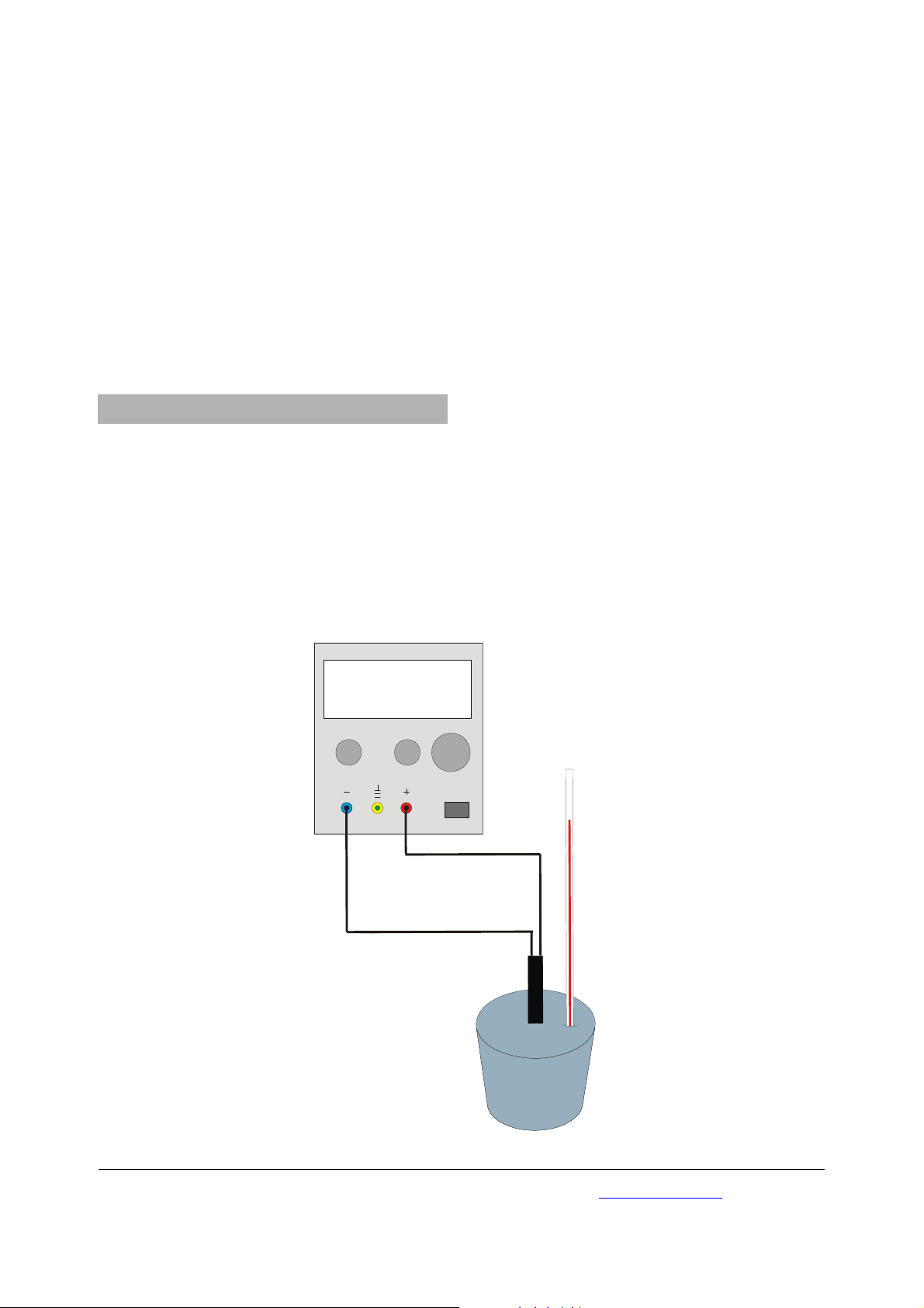
• Schaltung gemäß Fig. 1 herstellen.
• Netzgerät einschalten und einen Strom von ca. 4 A
einstellen. Danach Netzgerät wieder ausschalten.
1
Page 2
• Vor Start des Messlaufs einige Minuten warten.
Dann die Anfangstemperatur des
Kalorimeterzylinders ablesen.
• Netzgerät einschalten und gleichzeitig die
Zeitmessung starten.
• Abwarten bis die Temperatur um ca. 20° C
gestiegen ist. Zeit und Endtemperatur notieren.
Die spezifische Wärmekapazität ist gegeben durch die
Gleichung:
mit I: Strom, U: Spannung, t: Zeit, m: Masse des
Kalorimeterzylinders c: spezifische Wärmekapazität,
θ
: Anfangstemperatur, θ2: Endtemperatur
1
6.1 Hinweise zur Fehlerminimierung
Angenommen, dass die Strom- und Spannungsanzeigen hinreichend genau sind, liegen die zwei
Hauptfehlerquellen des Experiments beim Ablesen der
Temperatur und im Wärmeverlust.
Der Wärmeverlust ist davon abhängig, wie hoch die
Endtemperatur über der Raumtemperatur liegt. Er
lässt sich dadurch minimieren, dass der
Temperaturanstieg möglichst klein gehalten wird.
()
θ−θ⋅⋅=⋅⋅ cmtUI
12
6. Allgemeine Hinweise
U33020
Wenn die Ablesegenauigkeit des Thermometers 1° C
beträgt, dann ergibt sich ein relativ großer Fehler von
10% bei einem Temperaturanstieg um 10° C.
Deshalb gilt es einen Ausgleich zu finden zwischen
dem Fehler, der durch Wärmeverlust bei einem
großen Temperaturanstieg verursacht wird, und dem
relativ großen Fehler beim Ablesen der Temperatur
bei einer geringen Temperaturerhöhung.
Eine Erhöhung der Temperatur um 20° C ergibt eine
Fehlerquote von 5% (bei einer Ablesegenauigkeit des
Thermometers von 1° C) und einen relativ geringen
Fehler durch Wärmeverlust.
6.2 Vermeidung von Wärmeverlust nach Rumford
Nach Rumford kann der Wärmeverlust durch
folgenden Prozess vermieden werden. Wird der
Kalorimeterzylinder vor dem Experiment für einige
Stunden in einem Kühlschrank aufbewahrt, so liegt
seine Anfangstemperatur um θ unter Raumtemperatur. Wenn dann seine Endtemperatur um θ über
Raumtemperatur liegt, dann ist die aufgenommene
Wärmemenge, solange seine Temperatur unter
Raumtemperatur ist, gleich der Wärmemenge, die er
abgibt, wenn seine Temperatur über Raumtemperatur
ist. Es findet dann kein Wärmeverlust statt.
0 0 0 4
.
0...5 A 0...20 V
2 0 1
.
VA
Fig. 1 Experimenteller Aufbau
3B Scientific GmbH • Rudorffweg 8 • 21031 Hamburg • Deutschland • www.3bscientific.com
Technische Änderungen vorbehalten
© Copyright 2008 3B Scientific GmbH
Page 3
3B SCIENTIFIC® PHYSICS
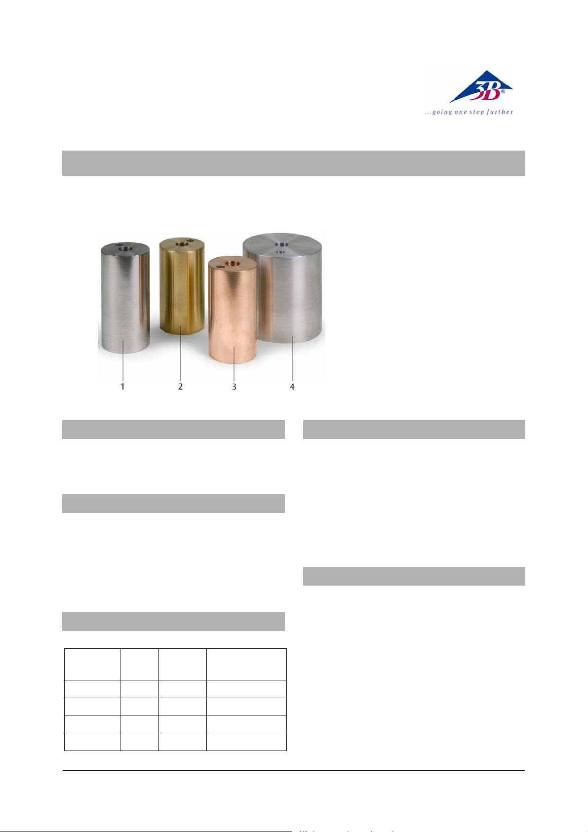
Set of 4 Metal Block Calorimeters U30070
Instruction Sheet
11/08 ALF
1 Steel calorimeter
2 Brass calorimeter
3 Copper calorimeter
4 Aluminium calorimeter
1. Safety instructions
There is a risk of burns from heater or calorimeter.
• Allow apparatus to cool before moving it.
2. Description
The set of 4 metal block calorimeters is used to
determine the specific heat capacity of aluminium,
brass, copper and steel.
The metal blocks are drilled with two holes to
accommodate an immersion heater (12.5 mm dia.)
and a thermometer or temperature probe (8 mm dia.).
3. Technical data
Mass of block: approx. 1 kg (±2% accuracy)
Material
Aluminium 84 75 896
Brass 84 44 377
Copper 85 43 385
Steel 92 44 452
Height
(mm)
Diameter
(mm)
Specific heat
J/(kg*K)
4. Additionally required equipment
1 DC Power Supply 0 - 20 V, 0 - 5 A (230 V, 50/60 Hz)
U33020-230
or
1 DC Power Supply 0 - 20 V, 0 - 5 A (115 V, 50/60 Hz)
U33020-115
1 Immersion Heater, 12 V U30075
1 Thermometer -20°C to +110°C U40911
1 Mechanical stopwatch, 30 min U40800
5. Operation
• Weigh the calorimeter block and record its mass.
• Place the calorimeter block on a heat proof mat
surrounded by insulation, so that the heat losses
are kept to the minimum.
• Insert the immersion heater and the thermometer
into the appropriate hole. Drop some oil or water
into the thermometer hole to ensure good
thermal contact between the thermometer and
the block.
• Set up the circuitry according fig. 1.
• Switch on the power supply and adjust it to give a
current of about 4 A. Switch the heater off.
1
Page 4

• Before starting the experimental run, wait for a
few minutes before taking the temperature of the
calorimeter block.
• Switch on the heater and start the clock.
• Wait until the temperature has risen about 20
o
C
and record the time and final temperature.
The specific heat capacity can then be calculated from
the equation:
()
θ−θ⋅⋅=⋅⋅ cmtUI
12
with I: current, U: voltage, t: time, m: mass of calorimeter block, c: specific heat capacity, θ
temperature, θ
: final temperature
2
: initial
1
6. General notes
6.1 Explanation of how to minimise the error
Assuming that the readings for the current and voltage
are reasonable accurate, the two main sources of error
in the experiment will be the readings of the
temperature change and the effects of any heat loss.
Obviously the heat loss will depend on the excess
temperature above the room temperature, so this can
be minimised by keeping the temperature rise as
small as possible.
U33020
If the thermometer can only be read accurately to 1
then a temperature rise of 10
o
would give a 10% error,
o
,
which is really too large for this type of experiment.
Therefore, it is a balance between the error
introduced by a large temperature increase causing
heat losses, and a small temperature increase giving a
large percentage error in the temperature readings. A
o
20
rise in temperature will give a 5% error in reading
the thermometer (assuming it can only be read
accurately to 1
o
) and a reasonable low error due to
heat loss.
6.2 Rumford’s correction
Rumford argued that heat losses could be eliminated
by the following process. If the metal block is kept in a
fridge for several hours before the experiment, then it
will start at, say, θ below room temperature. If its final
temperature after the experiment was θ above room
temperature, then the heat it took in while below
room temperature would be equal to the heat it gave
out while above room temperature, so there would be
no heat loss.
0 0 0 4
.
0...5 A 0...20 V
2 0 1
.
VA
3B Scientific GmbH • Rudorffweg 8 • 21031 Hamburg • Germany • www.3bscientific.com
Fig. 1 Experimental set up
Subject to technical amendment
© Copyright 2008 3B Scientific GmbH
Page 5

3B SCIENTIFIC® PHYSICS
Blocs calorimétriques en métal, jeu de 4 U30070
Manuel d'utilisation
11/08 ALF
1 Bloc calorimétrique, acier
2 Bloc calorimétrique, laiton
3 Bloc calorimétrique, cuivre
4 Bloc calorimétrique, aluminium
1. Consignes de sécurité
Risques de brûlures provenant de l'élément de
chauffage ou du calorimètre !
• Laissez toujours refroidir l'appareillage avant de
le démonter.
2. Description
Ces blocs calorimétriques en métal de forme
cylindrique servent à déterminer la capacité
thermique spécifique de l'aluminium, du laiton, du
cuivre et de l'acier.
Les blocs en métal présentent deux alésages
permettant d'y rattacher un thermoplongeur
(diamètre de 12,5 mm) et un thermomètre ou une
sonde de température (8 mm Ø).
3. Caractéristiques techniques
Masse de chaque bloc: env. 1 kg (précision de ±2%)
Matériau
Aluminium 84 75 896
Laiton 84 44 377
Cuivre 85 43 385
Acier 92 44 452
Hauteur
(mm)
Diamètre
(mm)
Chaleur
spécifique
J/(kg*K)
4 Accessoires supplémentaires requis
1 Alimentation CC 0 - 20 V, 0 - 5 A (230 V, 50/60 Hz)
U33020-230
ou
1 Alimentation CC 0 - 20 V, 0 - 5 A (115 V, 50/60 Hz)
U33020-115
1 Thermoplongeur, 12 V U30075
1 Thermomètre, -20°C - +110°C U40911
1 Chronomètre mécanique, 30 min U40800
5. Commande
• Pesez le bloc calorimétrique de forme cylindrique
et notez-en la masse.
• Posez le bloc calorimétrique de forme cylindrique
sur une surface résistant à la chaleur et
enveloppez-le d'un matériel isolant afin de
minimiser au maximum la déperdition de
chaleur.
• Insérez l'élément de chauffage et le thermomètre
dans les alésages correspondants. Mettez
auparavant quelques gouttes d'huile ou d'eau
dans l'alésage destiné au thermomètre afin
d'assurer un bon contact thermique entre le
thermomètre et le calorimètre.
• Formez le circuit conformément à la figure 1.
• Allumez le bloc d'alimentation et réglez un
courant d'environ 4 ampères. Éteignez ensuite de
nouveau le bloc d'alimentation.
1
Page 6

• Attendez quelques minutes avant de démarrer le
cycle de mesures. Relevez ensuite la température
initiale du bloc calorimétrique de forme
cylindrique.
• Allumez le bloc d'alimentation tout en démarrant
simultanément la mesure du temps.
• Attendez que la température soit montée à
environ 20° C. Notez le temps ainsi que la
température finale.
L'équation suivante permet d'obtenir la capacité
thermique spécifique :
I : étant le courant, U : étant la tension, t : étant le
temps, m : étant la masse du bloc calorimétrique de
forme cylindrique, c : étant la capacité thermique
spécifique, θ
étant la température finale
6.1 Conseils utiles permettant de minimiser les
erreurs
Si nous partons de l'hypothèse que les affichages de
courant et de tension sont suffisamment précis, dans
cet essai expérimental, les deux sources principales
d'erreurs sont d'une part liées à la lecture de la
température et d'autre part à la déperdition de
chaleur.
La déperdition de chaleur dépend de combien la
température finale dépasse la température ambiante.
Il est possible de minimiser cette déperdition en
réduisant autant que possible la montée en
température.
()
θ−θ⋅⋅=⋅⋅ cmtUI
12
: étant la température initiale et θ2 :
1
6. Remarques générales
U33020
Si la précision de lecture du thermomètre est de 1° C,
l'erreur relativement élevée prend alors une valeur de
10 % pour une montée en température de 10° C.
Il s'agit donc de trouver une compensation entre
d'une part l'erreur liée à la déperdition de chaleur
provenant d'une montée en température élevée et
d'autre part l'erreur relativement élevée se produisant
lors de la lecture de la température pour une
augmentation faible de température.
Une augmentation de la température de 20° C se
traduit par un taux d'erreur de 5 % (pour une
précision de lecture du thermomètre de 1° C) et un
taux d'erreur relativement faible lié à la déperdition
de chaleur.
6.2 Prévention d'une déperdition de chaleur selon
Rumford
Selon Rumford, il est possible d'éviter une déperdition
de chaleur en appliquant la procédure suivante. Si le
bloc calorimétrique de forme cylindrique est conservé
quelques heures au réfrigérateur avant l'essai
expérimental, sa température initiale est alors
inférieure de θ à la température ambiante. Lorsque
sa température finale dépasse la température
ambiante de θ, et tant que sa température est
supérieure à la température ambiante, la quantité de
chaleur absorbée est alors égale à la quantité de
valeur dégagée par le bloc calorimétrique lorsque sa
température est supérieure à la température
ambiante. Il ne se manifeste alors aucune déperdition
de chaleur.
0 0 0 4
.
0...5 A 0...20 V
3B Scientific GmbH • Rudorffweg 8 • 21031 Hamburg • Allemagne • www.3bscientific.com
Fig. 1 : Appareillage expérimental
Sous réserve de modifications techniques
© Copyright 2008 3B Scientific GmbH
2 0 1
.
VA
Page 7

3B SCIENTIFIC® PHYSICS
Blocchi calorimetrici di metallo, set di 4 U30070
Istruzioni per l'uso
11/08 ALF
1 Corpo calorimetro, acciaio
2 Corpo calorimetro, ottone
3 Corpo calorimetro, rame
4 Corpo calorimetro, alluminio
1. Norme di sicurezza
Pericolo di ustioni dovute all'elemento termico o al
barometro.
• Lasciare raffreddare l’apparecchio prima di
smontarlo.
2. Descrizione
Blocchi calorimetrici cilindrici in metallo, per la
determinazione della capacità termica specifica di
alluminio, ottone, rame e acciaio.
I blocchi di metallo presentano due fori in cui
posizionare un riscaldatore a immersione (12,5 mm Ø) e
un termometro o una sonda di temperatura (8 mm Ø).
3. Dati tecnici
Massa dei blocchi: ca. 1 kg (±2% precisione)
Materiale
Alluminio 84 75 896
Ottone 84 44 377
Rame 85 43 385
Acciaio 92 44 452
Altezza
(mm)
Diametro
(mm)
Calore specifico
J/(kg*K)
4. Altri apparecchi necessari
1 Alimentazione CC 0 - 20 V, 0 - 5 A (230 V, 50/60 Hz)
U33020-230
oppure
1 Alimentazione CC 0 - 20 V, 0 - 5 A (115 V, 50/60 Hz)
U33020-115
1 Riscaldatore a immersione, 12 V U30075
1 Termometro da -20°C a +110°C U40911
1 Cronometro meccanico, 30 min U40800
5. Utilizzo
• Pesare i cilindri calorimetrici e annotarne la
massa
• Collocare il cilindro calorimetrico su una base
resistente al calore e circondarlo con materiale
isolante in modo che la dispersione termica sia la
minore possibile.
• Inserire l'elemento termico e il termometro nei
fori corrispondenti. Versare prima alcune gocce
d'olio o di acqua nel foro del termometro, per
creare un buon contatto termico tra termometro e
calorimetro.
• Realizzare il collegamento come illustrato in Fig. 1.
• Attivare l'alimentatore e impostare una corrente
di ca. 4 A. Quindi spegnere di nuovo
l'alimentatore.
1
Page 8

• Attendere alcuni minuti prima di avviare
l'esecuzione della misura. Leggere quindi la
temperatura iniziale del cilindro calorimetrico.
• Accendere l'alimentatore e contemporaneamente
avviare la misurazione del tempo.
• Attendere fino a che la temperatura non è salita
fino a circa 20°C. Annotare tempo e temperatura
finale.
La capacità termica specifica è data dall'equazione:
con I: corrente, U: tensione, t: tempo, m: massa del
cilindro calorimetrico c: capacità termica specifica, θ
temperatura iniziale, θ
6.1 Indicazioni per la minimizzazione degli errori
Assunto che le indicazioni della corrente e della
temperatura siano sufficientemente esatte, le due
fonti principali di errore dell'esperimento stanno
nella lettura della temperatura e nella dispersione
termica.
La dispersione termica dipende da quanto la
temperatura finale è superiore alla temperatura
ambiente. Essa può essere minimizzata grazie al fatto
che l'incremento di temperatura viene mantenuto il
più basso possibile.
()
θ−θ⋅⋅=⋅⋅ cmtUI
12
: temperatura finale
2
6. Indicazioni generali
U33020
:
1
Se la precisione di lettura del termometro è pari a 1°
C, risulta n errore relativamente grande del 10% in
caso di un incremento di temperatura di 10° C.
Pertanto si tratta di trovare un compromesso tra
l'errore dovuto alla dispersione termica, in caso di un
elevato incremento di temperatura, e l'errore
relativamente grande nella lettura della temperatura
in caso di un aumento della temperatura ridotto.
Un aumento della temperatura di 20° C dà come
risultato una percentuale di errore del 5% (con una
precisione di lettura del termometro di 1° C) e un
errore relativamente ridotto a causa della dispersione
termica.
6.2 Evitare la dispersione termica in base a Rumford
Secondo Rumford la dispersione termica può essere
evitata mediante il seguente processo. Se il cilindro
calorimetrico prima dell'esperimento viene
conservato per alcune ore in un frigorifero, la sua
temperatura iniziale rispetto alla temperatura
ambiente è θ volte inferiore.
Se in seguito allo svolgimento dell’esperimento la
temperatura del calorimetro è θ superiore alla
temperatura ambiente, la quantità di calore assorbita
è pari alla quantità di calore che esso cede,
fintantoché la sua temperatura non cala al di sotto
della temperatura ambiente. Non avviene quindi
nessuna dispersione termica.
0 0 0 4
.
0...5 A 0...20 V
2 0 1
.
VA
Fig. 1 Struttura sperimentale
3B Scientific GmbH • Rudorffweg 8 • 21031 Amburgo • Germania • www.3bscientific.com
Con riserva di modifiche tecniche
© Copyright 2008 3B Scientific GmbH
Page 9

3B SCIENTIFIC® PHYSICS
Calorímetros de bloque de metal, juego de 4 U30070
Instrucciones de uso
11/08 ALF
1 Bloque calorimétrico, acero
2 Bloque calorimétrico, latón
3 Bloque calorimétrico, cobre
4 Bloque calorimétrico, aluminio
1. Advertencias de seguridad
Peligro de quemaduras por elemento calentador o por
el calorímetro.
• Deje enfriar el aparato antes de desmontarlo.
2. Instrucciones de uso
Bloques cilíndricos calorímetros, de metal, para la
determinación del calor específico del aluminio, del
latón, del cobre y del acero.
En los bloques de metal se han practicado dos
perforaciones para el alojamiento de un calentador
sumergible (12,5 mm de diámetro), y un termómetro o
una punta de sonda de temperatura (diámetro de 8 mm).
3. Datos técnicos
Peso de bloque: aprox. 1 kg (±2% de exactitud)
Material
Aluminio 84 75 896
Latón 84 44 377
Cobre 85 43 385
Acero 92 44 452
Altura
(mm)
Diámetro
(mm)
Calor específico
J/(kg*K)
4. Aparatos requerdos adicionalmente
1 Fuente de alimentación de c.c. 0 - 20 V, 0 - 5 A (230 V, 50/60 Hz)
U33020-230
o
1 Fuente de alimentación de c.c. 0 - 20 V, 0 - 5 A (115 V, 50/60 Hz)
U33020-115
1 Calentador sumergible, 12 V U30075
1 Termómetro de,-20°C a +110°C U40911
1 Cronómetro mecánico, 30 min U40800
5. Manejo
• Se pesa el calorímetro y se anota su masa.
• Se coloca el cilindro calorimétrico sobre una
superficie resistente al calor y se envuelve con
material aislante al calor para que la pérdida de
calor sea mínima.
• Se insertan el elemento calentador y el
termómetro en sus correspondientes orificios.
Antes se vierten unas gotas de aceite o de agua en
el orificio del termómetro, para lograr un buen
contacto entre el termómetro y el calorímetro.
• Se realiza el circuito según la Fig. 1.
• Se conecta la fuente de alimentación y se ajusta
una corriente de 4 A. Se desconecta nuevamente
la fuente de alimentación.
1
Page 10

• Antes del inicio de la serie de mediciones se
esperan unos minutos. Luego se lee y anota la
temperatura inicial del cilindro calorimétrico.
• Se conecta la fuente de alimentación y al mismo
tiempo se inicia la medición del tiempo.
• Se espera a que la temperatura haya aumentado
en unos 20° C. Se anotan el tiempo y la
temperatura final.
La capacidad calorífica específica se obtiene de la
ecuación:
con I: Corriente, U: Tensión, t: Tiempo, m: Masa del
cilindro calorimétrico c: Capacidad calorífica
específica, θ
final
6.1 Indicaciones para minimizar los errores
Suponiendo que las indicaciones para la corriente y la
tensión son lo suficientemente exactas, las principales
fuentes de errores en el experimento se encuentran
en la lectura de la temperatura y en la pérdida de
calor.
La perdida de calor depende de que tan alta sea la
temperatura final con respecto a la temperatura
ambiente. Ésta se puede minimizar haciendo que el
aumento de la temperatura sea lo más mínimo
posible.
()
θ−θ⋅⋅=⋅⋅ cmtUI
12
: Temperatura inicial, θ2: Temperatura
1
6. Indicaciones generales
U33020
Cuando la exactitud de lectura del termómetro es de
1° C , entonces se tiene un error grande del 10%
cuando se tiene un aumento de temperatura de 10° C.
Se trata por lo tanto de encontrar una compensación
entre el error que se origina por la pérdida de calor
durante un aumento de temperatura grande y el error
grande en la lectura con aumento de temperatura
bajo.
Un aumento de temperatura en 20° C da una
proporción de error del 5% (con una exactitud de
medida del termómetro de 1° C) y un error
relativamente bajo por pérdida de calor.
6.2 Prevención de pérdida de calor según Rumford
Según Rumford es posible prevenir la pérdida de calor
con el siguiente proceso. Si antes de iniciar el
experimento el cilindro calorimétrico se coloca por
varias horas en un refrigerador, su temperatura inicial
estará ahora en θ por debajo de la temperatura
ambiente. Entonces cuando su temperatura final se
encuentre en θ por encima de la temperatura
ambiente, la cantidad de calor absorbida mientras la
temperatura está por debajo de la del ambiente es
igual a la cantidad de calor entregada cuando su
temperatura final está en el mismo θ por encima de la
temperatura del ambiente. No tiene lugar una
pérdida de calor.
0 0 0 4
.
0...5 A 0...20 V
Fig. 1 Montaje de experimentación
2 0 1
.
VA
3B Scientific GmbH • Rudorffweg 8 • 21031 Hamburgo • Alemania • www.3bscientific.com
Se reservan las modificaciones técnicas
© Copyright 2008 3B Scientific GmbH
Page 11

3B SCIENTIFIC® PHYSICS
Calorímetro de bloco de metal, jogo de 4 U30070
Manual de instruções
11/08 ALF
1 Bloco calorímetro, aço
2 Bloco calorímetro, latão
3 Bloco calorímetro,
4 Bloco calorímetro, alumínio
cobre
1. Indicações de segurança
Perigo de queimaduras pelo elemento de
aquecimento ou calorímetro.
• Deixar esfriar o aparelho antes da desmontagem.
2. Descrição
Blocos cilíndricos calorímetros de metal para a
determinação da capacidade de calor específico do
alumínio, do bronze, do cobre e do aço.
Os blocos de metal são perfurados com dois furos para
acomodar um aquecedor de imersão (12,5 mm de
diâmetro) e um termômetro ou sensor de temperatura
(8 mm Ø).
3. Dados técnicos
Massa do bloco: aprox. 1 kg (± % de precisão)
Material
Alumínio 84 75 896
Latão 84 44 377
Cobre 85 43 385
Aço 92 44 452
Altura
(mm)
Diâmetro
(mm)
Calor específico
J/(kg*K)
4. Aparelhos adicionalmente exigidos
1 Fonte de alimentação DC 0 - 20 V, 0 - 5 A (230 V, 50/60 Hz)
U33020-230
ou
1 Fonte de alimentação DC 0 - 20 V, 0 - 5 A (115 V, 50/60 Hz)
U33020-115
1 Aquecedor de imersão, 12 V U30075
1 Termômetro, -20°C a +110°C U40911
1 Cronômetro mecânico, 30 min U40800
5. Operação
• Pesar o calorímetro de cilindro e anotar a massa.
• Colocar o calorímetro de cilindro sobre uma base
resistente ao calor e envolve-lo com material
isolante para que a perda de calor seja a menor
possível.
• Inserir o elemento aquecedor e o termômetro nas
suas respectivas furações. Antes colocar algumas
gotas de óleo ou água na furação do termômetro,
para estabelecer um bom contacto térmico entre
o termômetro e o calorímetro.
• Estabelecer a ligação segundo Fig. 1.
• Ligar a fonte de alimentação e colocar uma
corrente de aprox. 4 A. Depois desligar a fonte de
alimentação de novo.
1
Page 12

• Esperar alguns minutos antes de começar o curso
das medições. Depois ler a temperatura de inicio
do calorímetro de cilindro.
• Ligar a fonte de alimentação e ao mesmo tempo
começar a medição de tempo.
• Esperar até a temperatura aumentar em aprox.
20° C. Anotar o tempo e a temperatura final.
A capacidade de calor específica é dada por meio da
equação:
com I: Corrente, U: Tensão, t: Tempo, m: Massa do
calorímetro de cilindro c: Capacidade de calor
específica, θ
final
6.1 Indicações para a minimização de erros
Supondo que as marcações de corrente e tensão sejam
suficientemente exatas, as duas fontes de erro
encontram-se na leitura da temperatura e na perda de
calor.
A perda de calor é dependente de quanto alta à
temperatura final se encontre acima da temperatura
do ambiente. Ela pode ser minimizada, em que, no
possível, o aumento de temperatura seja mantido
pequeno.
()
θ−θ⋅⋅=⋅⋅ cmtUI
12
: Temperatura inicial, θ2: Temperatura
1
6. Indicações gerais
U33020
Quando a precisão de leitura do termômetro é de 1°
C, então resulta um erro relativamente grande de 10%
num aumento de temperatura em 10° C.
Por isso vale encontrar um equilíbrio entre o erro, que
é causado pela perda de calor num aumento de
temperatura muito acentuado, e do erro
relativamente grande na leitura de um aumento de
temperatura baixo.
Um aumento de temperatura em 20° C resulta numa
quota de erro de 5% (numa precisão de leitura do
termômetro de 1° C) e um erro relativamente
pequeno por perda de calor.
6.2 Evitação da perda de calor segundo Rumford
Segundo Rumford a perda de calor pode ser evitada
pelo seguinte processo. Se o calorímetro de cilindro
for guardado por algumas horas num refrigerador
antes da experiência, então a sua temperatura inicial
encontra-se por θ abaixo da temperatura de
ambiente. Se a seguir a sua temperatura final está em
θ acima da temperatura de ambiente, então a
quantidade de calor recebida, enquanto a sua
temperatura está abaixo da temperatura de ambiente,
é igual à quantidade de temperatura que ele cede,
quando a sua temperatura está acima da temperatura
de ambiente. Então não dará lugar a nenhuma perda
de calor.
0 0 0 4
.
0...5 A 0...20 V
2 0 1
.
VA
Fig. 1 Montagem experimental
3B Scientific GmbH ▪ Rudorffweg 8 ▪ 21031 Hamburgo ▪ Alemanha ▪ www.3bscientific.com
Sob reserva de alterações técnicas
© Copyright 2008 3B Scientific GmbH
 Loading...