

Page 1
3B SCIENTIFIC® PHYSICS
Set of 4 Metal Block Calorimeters U30070
Instruction Sheet
11/08 ALF
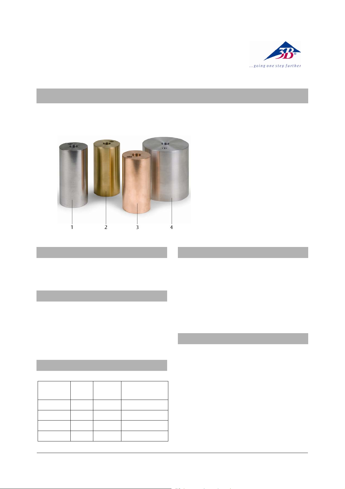
1 Steel calorimeter
2 Brass calorimeter
3 Copper calorimeter
4 Aluminium calorimeter
1. Safety instructions
There is a risk of burns from heater or calorimeter.
• Allow apparatus to cool before moving it.
2. Description
The set of 4 metal block calorimeters is used to
determine the specific heat capacity of aluminium,
brass, copper and steel.
The metal blocks are drilled with two holes to
accommodate an immersion heater (12.5 mm dia.)
and a thermometer or temperature probe (8 mm dia.).
3. Technical data
Mass of block: approx. 1 kg (±2% accuracy)
Material
Aluminium 84 75 896
Brass 84 44 377
Copper 85 43 385
Steel 92 44 452
Height
(mm)
Diameter
(mm)
Specific heat
J/(kg*K)
4. Additionally required equipment
1 DC Power Supply 0 - 20 V, 0 - 5 A (230 V, 50/60 Hz)
U33020-230
or
1 DC Power Supply 0 - 20 V, 0 - 5 A (115 V, 50/60 Hz)
U33020-115
1 Immersion Heater, 12 V U30075
1 Thermometer -20°C to +110°C U40911
1 Mechanical stopwatch, 30 min U40800
5. Operation
• Weigh the calorimeter block and record its mass.
• Place the calorimeter block on a heat proof mat
surrounded by insulation, so that the heat losses
are kept to the minimum.
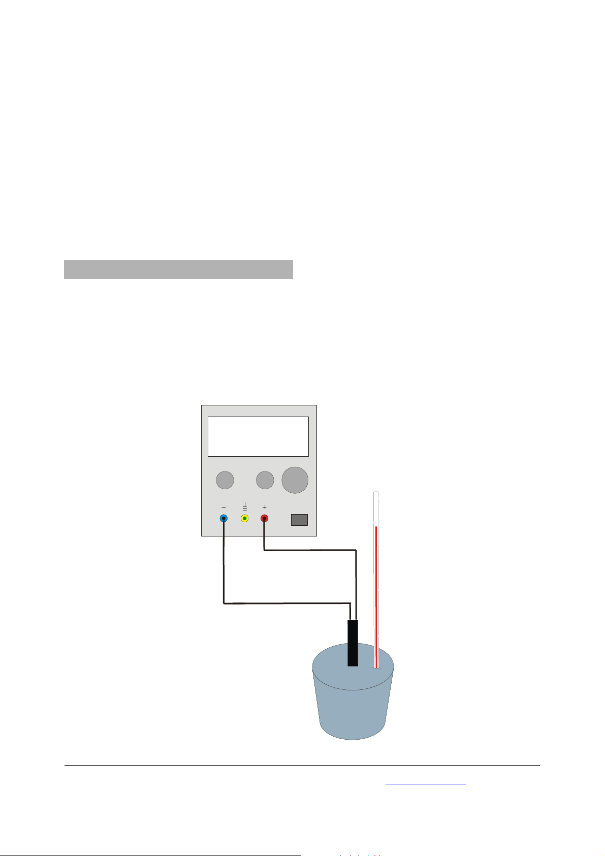
• Insert the immersion heater and the thermometer
into the appropriate hole. Drop some oil or water
into the thermometer hole to ensure good
thermal contact between the thermometer and
the block.
• Set up the circuitry according fig. 1.
• Switch on the power supply and adjust it to give a
current of about 4 A. Switch the heater off.
1
Page 2
• Before starting the experimental run, wait for a
few minutes before taking the temperature of the
calorimeter block.
• Switch on the heater and start the clock.
• Wait until the temperature has risen about 20
o
C
and record the time and final temperature.
The specific heat capacity can then be calculated from
the equation:
()
θ−θ⋅⋅=⋅⋅ cmtUI
12
with I: current, U: voltage, t: time, m: mass of calorimeter block, c: specific heat capacity, θ
temperature, θ
: final temperature
2
: initial
1
6. General notes
6.1 Explanation of how to minimise the error
Assuming that the readings for the current and voltage
are reasonable accurate, the two main sources of error
in the experiment will be the readings of the
temperature change and the effects of any heat loss.
Obviously the heat loss will depend on the excess
temperature above the room temperature, so this can
be minimised by keeping the temperature rise as
small as possible.
U33020
If the thermometer can only be read accurately to 1
then a temperature rise of 10
o
would give a 10% error,
o
,
which is really too large for this type of experiment.
Therefore, it is a balance between the error
introduced by a large temperature increase causing
heat losses, and a small temperature increase giving a
large percentage error in the temperature readings. A
o
20
rise in temperature will give a 5% error in reading
the thermometer (assuming it can only be read
accurately to 1
o
) and a reasonable low error due to
heat loss.
6.2 Rumford’s correction
Rumford argued that heat losses could be eliminated
by the following process. If the metal block is kept in a
fridge for several hours before the experiment, then it
will start at, say, θ below room temperature. If its final
temperature after the experiment was θ above room
temperature, then the heat it took in while below
room temperature would be equal to the heat it gave
out while above room temperature, so there would be
no heat loss.
0 0 0 4
.
0...5 A 0...20 V
2 0 1
.
VA
3B Scientific GmbH • Rudorffweg 8 • 21031 Hamburg • Germany • www.3bscientific.com
Fig. 1 Experimental set up
Subject to technical amendment
© Copyright 2008 3B Scientific GmbH
 Loading...