

Page 1

3B SCIENTIFIC
Instruction sheet
06/09 SP
®
PHYSICS
Maxwell’s wheel U8408305
1 Maxwell’s wheel
2 Axle hub
3 String
4 Clamps with adjusting screw
5 Hanger rail
1. Description
Maxwell’s wheel is used to demonstrate the conversion of kinetic energy into potential energy and
vice versa.
The wheel is suspended by two strings from a supporting rail. The adjusting screws on the clamps are
used for setting the horizontal alignment of the
wheel. Two axle hubs fitted at the end of the axle
prevent the wheel from breaking out during its upand-down motion.
2. Technical data
Wheel diameter: 130 mm
Weight of the wheel: 470 g
Moment of inertia: 10 kg cm²
Hanger rail: 370 mm x 12 mm dia.
3. Operation
For setting up Maxwell’s wheel, the following apparatus is additionally required:
1 Retort stand, H-base U8611130
2 Stainless steel rods, 1000 mm U15004
2 Universal clamps U13255
• Set up the stand rods on the base as shown in
Fig. 1.
• Attach the clamps supporting Maxwell’s wheel
to the horizontal rod.
• Use the adjustment screws to align the wheel
so that the axle is in a horizontal position.
• Gradually move the wheel upwards winding
the strings around the axle. Make sure that the
axle remains in a horizontal position. If necessary, readjust the strings.
• With the wheel at its maximum height, start
the movement of the wheel.
1
Page 2
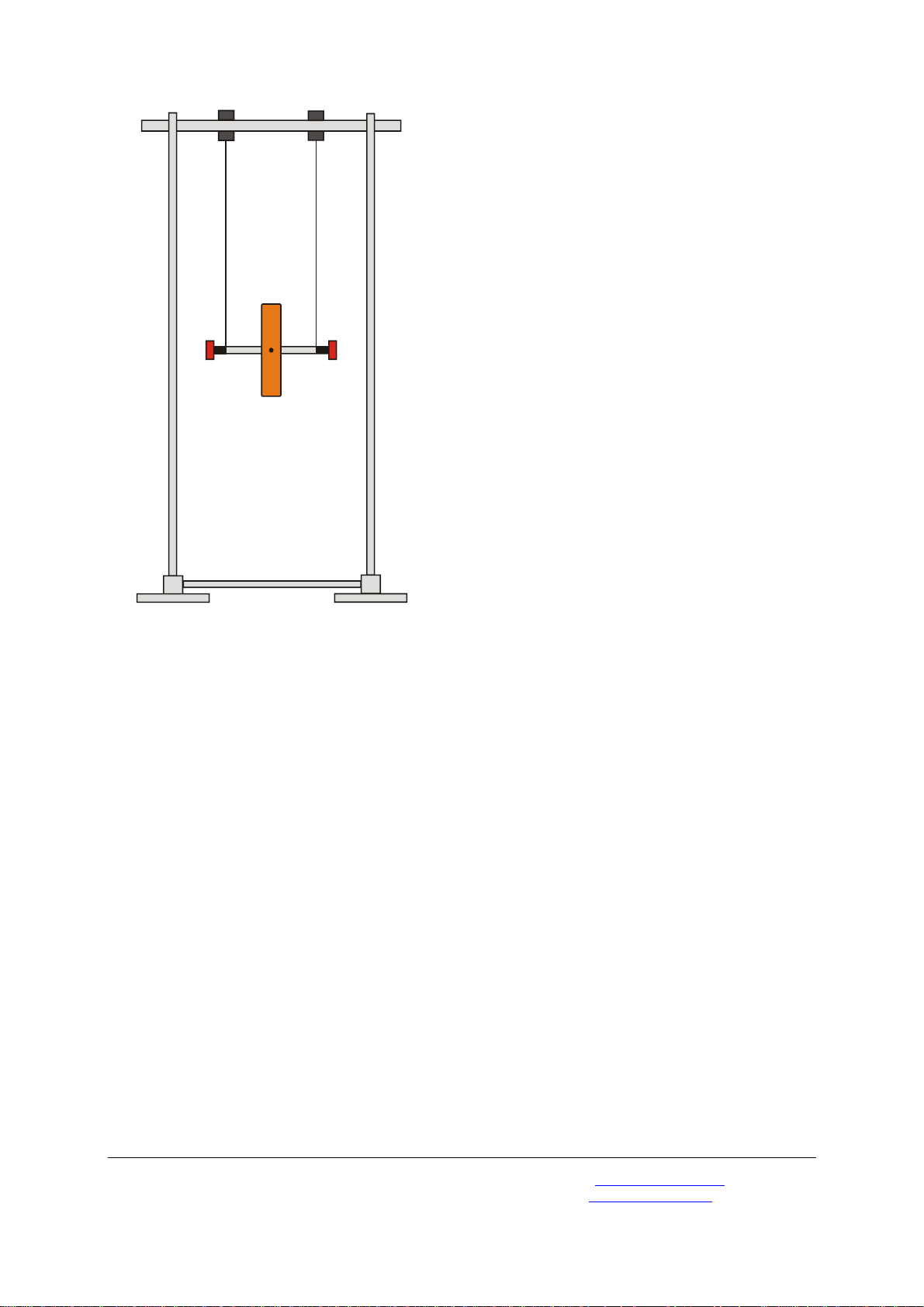
Fig. 1: Experimental set-up of Maxwell’s wheel
Elwe Didactic GmbH • Steinfelsstr. 6 • 08248 Klingenthal • Germany • www.elwedidactic.com
3B Scientific GmbH • Rudorffweg 8 • 21031 Hamburg • Germany • www.3bscientific.com
Subject to technical amendments
© Copyright 2009 3B Scientific GmbH
 Loading...