

Page 1
3B SCIENTIFIC
Magnetic Field Sensor ±2000 mT 1009941
Instruction Sheet
04/12 Hh
®
PHYSICS
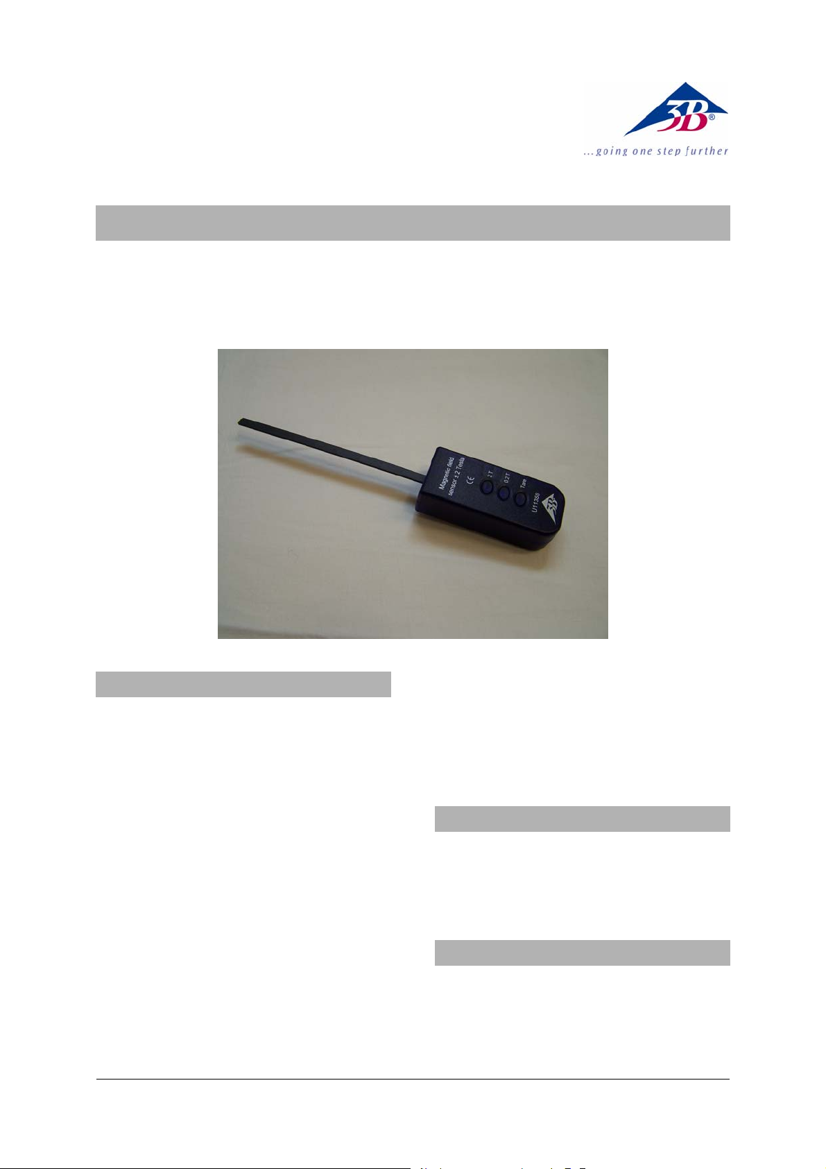
1. Description
Sensor box with attached sensor probe, 140
mm long, 7 mm wide and 1.9 mm thick, for
measuring magnetic flux density B of a mag-
netic field acting outside the box in a tangential
plane, primarily for use with the basic Halleffect apparatus (1009934).
At the tip of the probe there is a Hall sensor
with an active area of about 0.044 mm², which
produces a steady output signal that is ratiometric (i.e., proportional to the operating voltage).
The Hall sensor has an extended temperature
range of -20°C to +180°C for measuring the flux
density of heated germanium semiconductor
crystals (probes).
There are two latching range buttons for 0.2 T
and 2 T plus an additional Tare button for calibration. The current setting of the measurement range is shown visually by a light-emitting
diode on the left of the relevant button.
The stand clamping rod can be adjusted to
hold the sensor in the desired position and
orientation in the magnetic field that is being
measured.
The box is also suitable for use with the connector box (115 V, 50/60 Hz) (1009954) or connector
box (230 V, 50/60 Hz) (1009955). See the relevant technical data.
2. Safety instructions
The magnetic field sensor is not suitable for
applications where safety is essential.
• Only use the magnetic field sensor for
educational purposes!
3. Equipment supplied
1 sensor box with permanently attached probe
1 miniDIN 8-pin connecting cable, 60 cm
1 clamping rod, length 120 mm
1 instruction sheet
1
Page 2

4. Technical data
Measurement ranges: 200 mT, 2000 T
Configuration: Tangential
Sensor type: Linear Hall-effect
sensor
Position of Hall sensor: 135 mm, with refer-
ence to the front of the
sensor box casing
Tare range:
200 mT range: +/- 100 mT
2 T range: +/- 1 T
Non-linearity: Max. ±1,5 % of the
total measurement
range
Temperature dependence:
() ( )
⎡
,KBTB
⎢
⎣
T
⎛
⎜
K
⎝
⎤
⎞
−⋅−⋅= 3000008801300
⎟
⎥
⎠
⎦
When used with a connector box
200 mT range: Conversion factor:
125 mT/V, 1.60 V at
200 mT
2 T range: Conversion factor:
1250 mT/V, 1.60 V at
2000 mT
5. Operation
Note:
• To avoid permanent damage to the Hall
sensor in the sensor probe tip, do not subject it to any mechanical pressure!
• Do not bend the sensor probe tip!
• Hold the sensor box by hand in the mag-
netic field to be measured, or use the
clamping rod to position it as required in
the experimental setup.
• Set the tangential orientation of the sensor
element as required and measure the
magnetic field.
• Insert the sensor probe vertically through
the positioning hole marked "MFS" on the
top of the basic Hall-effect apparatus till it
comes to rest. The centre of the active surface on the sensor will then be within the
uniform magnetic field of the electromagnet and right next to the semiconductor crystal.
• Read off the value of the magnetic flux
density from the 3B NETlog
The sensor box is automatically detected by
the 3B NETlog
TM
unit.
Any change in the measuring range is auto-
matically transmitted to the 3B NETlog
TM
display.
TM
unit.
5.1 Zero calibration for the sensor box
• When a measuring range has been se-
lected, hold down the Tare button for about
1 s. Zero calibration is carried out automatically.
The zero display follows on the 3B NETlog
TM
display row corresponding to the selected sensor input.
• Under certain circumstances it may be
necessary to carry out zero calibration
again between measurements.
• Zero calibration should not be carried out
inside the pole pieces of a transformer.
The poles may possess some remanence
which would need to be taken into account.
6. Experimental applications
Magnetic fields of permanent magnets and
coils
Hysteresis of transformers
Remanence
Saturation effects in ferrite cores
7. Sample experiment
Experiment to measure magnetic flux density involving the Hall effect in semiconductors
Equipment needed:
TM
1 3B NETlog
(115 V, 50/60 Hz) 1000539
1 Transformer with Rectifier (115 V, 50/60 Hz)
1003315
1 DC Power Supply 20 V, 5 A (115 V, 50/60 Hz)
1003311
or
1 3B NETlog
TM
(230 V, 50/60 Hz) 1000540
1 Transformer with Rectifier (230 V, 50/60 Hz)
1003316
1 DC Power Supply 20 V, 5 A (230 V, 50/60 Hz)
1003312
1 Hall Effect Basic Apparatus 1009934
1 P-Doped Ge on Circuit Board 1009810
or
1 N-Doped Ge. on Circuit Board 1009760
1 Magnetic Field Sensor ±2000 mT 1009941
1 U Core 1000979
2 Coils D with 600 Taps 1000988
1 Pair of Pole Shoes 1009935
1 Set of 15 Safety Experiment Leads 1002843
• Set up the experiment as in Fig. 1.
• Switch the transformer and rectifier to the
12-V setting to supply the basic Hall-effect
apparatus with 12 V AC.
2
Page 3

• Select the 2-T range on the magnetic field
sensor and press the Tare button.
• Insert the magnetic field sensor into the
positioning hole marked "MFS".
• Set the DC power supply to constant-
current mode, i.e. turn the current-setting
potentiometer all the way to the left (0 A)
and the voltage-setting potentiometer all
the way to the right (20 V).
• Increase the current in the series circuit
including the transformer coils from 0 A to
2 A in steps of 0.1 A.
• You may also measure the current in the
coils using the current measurement input
of the 3B NETlog
TM
unit (measuring range
2 A DC) and include those measurements
in your evaluation of the experiment.
Example results:
For a pole-piece separation of 8 mm and val-
ues of 10.6 V and 1.74 A the flux density will
be 300 mT.
. Care and maintenance
• Before cleaning the equipment, disconnect
it from its power supply.
• Use a soft, damp cloth to clean it.
9. Disposal
• The packaging should be disposed of at
local recycling points.
• Should you need to dispose of the equip-
ment itself, never throw it away in normal
domestic waste. Local regulations for the
disposal of electrical equipment will apply.
Fig. 1 Measurement of flux density in the air gap between pole pieces of an electro-magnet in an experiment set-
up using the basic Hall-effect apparatus
3B Scientific GmbH ▪ Rudorffweg 8 ▪ 21031 Hamburg ▪ Germany ▪ www.3bscientific.com
Subject to technical amendments
© Copyright 2012 3B Scientific GmbH
Page 4

 Loading...