

Page 1
3B SCIENTIFIC
Magnetfeldsensor ±2000 mT
1009941 / U11359
Bedienungsanleitung
10/11 Hh
®
PHYSICS
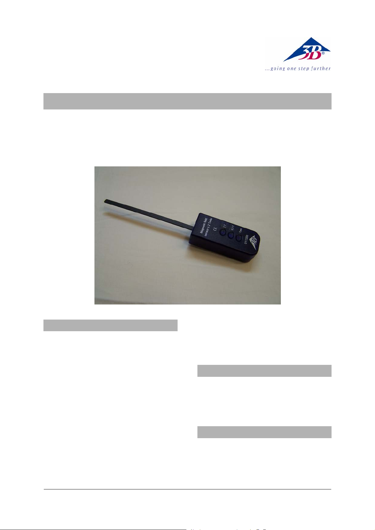
1. Beschreibung
Sensorbox mit angebautem 140 mm langem, 7 mm
breitem und 1,9 mm dickem Fühlerteil zur Messung der magnetischen Flußdichte B eines von
aussen einwirkenden Magnetfeldes in tangentialer
Richtung, vornehmlich für das Hall-EffektGrundgerät (1009934 / U8487000).
Auf der Fühlerspitze befindlicher Hall-Sensor mit
einer aktiven Fläche von ca. 0,044 mm² mit stetigem ratiometrischem (d.h. der Betriebsspannung
proportionalem) Ausgangssignal.
Erweiterter Temperaturbereich des Hall-Sensors von
- 20 °C ... + 180 °C für die Flussdichtenmessung an
geheizten Germanium-Halbleiterkristallen (Probes).
Zwei Bereichstasten mit 0,2 T und 2 T mit EinrastFunktion und einer zusätzlichen Tara-Taste. Optische Anzeige des aktuell eingeschalteten Messbereichs mit einer Leuchtdiode links neben der Taste.
Möglichkeit der Stativstangenbefestigung zur definierten Orientierung im zu messenden Magnetfeld.
Auch für den Betrieb mit der Anschlussbox (115 V,
50/60 Hz) (1009954 / U8533381-115) bzw. Anschlussbox (230 V, 50/60 Hz) (1009955 / U8533381-
230) geeignet; siehe hierzu die Technischen Daten.
2. Sicherheitshinweis
Der Magnetfeldsensor ist nicht für sicherheitsrelevate Anwendungen geeignet!
• Magnetfeldsensor nur für Ausbildungszwecke
einsetzen!
3. Lieferumfang
1 Sensorbox mit fest angebautem Fühlerteil
1 miniDIN-Anschlusskabel 8-pin, 60 cm lang
1 Stativstange, 120 mm lang
1 Bedienungsanleitung
1
Page 2

4. Technische Daten
Messbereiche: 200 mT, 2000 T
Konfiguration: tangential
Sensortyp: Linearer Hall-Effekt-
Sensor
Position des Hall-Sensors: 135 mm,
bezogen auf die Stirnfläche des Sensorboxgehäuses
Tarabereich:
im 200 mT Bereich: +/- 100 mT
im 2 T Bereich: +/- 1 T
Max. Nichtlinearität: ±1,5 % vom gesamten
Messbereich
Temperaturabhängigkeit:
() ( )
⎡
,KBTB
⎢
⎣
T
⎛
⎜
K
⎝
⎤
⎞
−⋅−⋅= 3000008801300
⎟
⎥
⎠
⎦
Verwendung mit der Anschlussbox
im 200 mT-Bereich: Übertragungsfaktor:
125 mT/V; 1,60 V bei
200 mT
im 2 T-Bereich: Übertragungsfaktor:
1250 mT/V; 1,60 V bei
2000 mT
5. Bedienung
Hinweis:
• Um dauerhafte Beschädigungen des in die
Fühlerspitze eingesetzten Hall-Sensors zu vermeiden, diesen keinen mechanischen Pressdrücken aussetzen!
• Fühlerspitze nicht verbiegen!
• Die Sensorbox in das zu messende Magnetfeld
halten oder ggfs. mit dem Stativstab versehen
und hieran am Versuchsaufbau befestigen.
• Die tangentiale Orientierung des Sensorele-
mentes beachten und das Magnetfeld ausmessen.
• Das Sensorelement durch die an der Oberkante
im Hall-Effekt-Grundgerät befindliche Positionierdurchführung "MFS" senkrecht bis zur mechanischen Auflage eintauchen. Hierbei befindet sich das Zentrum der aktiven Fläche des
Sensorelements im homogenen Feld des Elektromagneten und direkt am Halbleiterkristall.
• Im Display des 3B NETlog
TM
den Wert der mag-
netischen Flußdichte ablesen.
Die Sensorbox besitzt eine automatische Erkennung
durch das 3B NETlog
Eine Umschaltung des Messbereichs wird zum 3B
TM
NETlog
übertragen.
TM
.
5.1 Nullpunkt-Abgleich der Sensorbox
• Im gewählten Messbereich die Tara (Tare)-Taste
ca. 1 s lang drücken. Der Abgleich erfolgt automatisch.
Es erfolgt eine Aktualisierung der Null-Anzeige in
der 3B NETlog
TM
-Displayzeile des gewählten Sensor-
eingangs.
• Wenn erforderlich, ist der Nullpunkt-
Abgleichsvorgang zwischen den Messungen zu
wiederholen.
• Nullpunkt-Abgleich ausserhalb der Polschuhe
eines Transformators durchführen! Die Polschuhe besitzen ggf. bereits eine Remanenz,
die berücksichtigt werden muss!
6. Anwendungen
Magnetfelder von Permanentmagneten und Spulen
Hysterese von Transformatoren
Remanenz
Sättigungseffekte in Eisenkernen
7. Experimentierbeispiel
Messung der magnetischen Flussdichte im Experiment zum Hall-Effekt an Halbleitern
Benötigte Geräte:
1 3B NETlog
TM
(115 V, 50/60 Hz) 1000539
U11300-115
1 Transformator mit Gleichrichter (115 V, 50/60 Hz)
1003315
U33020-115
1 DC-Netzgerät 0 ... 20 V, 0 ... 5 A (115 V, 50/60 Hz)
1003311
U33300-115
oder
1 3B NETlog
TM
(230 V, 50/60 Hz) 1000540
U11300-230
1 Transformator mit Gleichrichter (230 V, 50/60 Hz)
1003316
U33300-230
1 DC-Netzgerät 0 ... 20 V, 0 ... 5 A (230 V, 50/60 Hz)
1003312
U33020-230
1 Hall-Effekt-Grundgerät 1009934
U8487000
1 p-Ge auf Leiterplatte 1009810
U8487020
oder
1 n-Ge auf Leiterplatte 1009760
U8487030
1 Magnetfeldsensor ±2000 mT 1009941
U11359
1 U-Kern 1000979
U8497215
2
Page 3
2 Spulen D mit 600 Windungen 1000988
U8497430
1 Paar Polschuhe mit Spannbügel 1009935
U8497205
1 Satz Sicherheitsexperimentierkabel 1002843
U138021
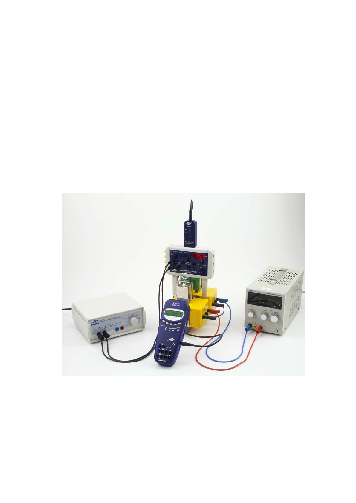
• Experiment gemäß Fig. 1 . aufbauen
• Den Transformator mit Gleichrichter auf 12 V
schalten und das Hall-Effekt-Grundgerät mit 12 V
Wechselspannung versorgen.
• Am Magnetfeldsensor den Messbereich 2 T
wählen und die Tara-Taste betätigen.
• Den Magnetfeldsensor in die Positionierdurch-
führung "MFS" einschieben.
• Das DC-Netzgerät auf Konstantstrombetrieb
einstellen, d.h.: Stromsteller-Potenziometer
auf Linksanschlag (0 A), SpannungsstellerPotenziometer auf Rechtsanschlag (20 V).
• Den Strom in der Reihenschaltung der Trans-
formatorspulen von 0 A bis 2 A in Schritten von
0,1 A erhöhen.
• Ggf. den Spulenstrom über den Strommessein-
gang des 3B NETlog
TM
führen (Messbereich 2 A
DC)) und die Messwerte in die Experimentauswertung einbeziehen.
Exemplarisches Ergebnis:
Bei einem Polschuhabstand von 8 mm und den
Werten 10,6 V und 1,74 A wird eine Flussdichte von
300 mT erreicht.
Fig. 1 Messung der Flussdichte im Luftspalt zwischen den Polschuhen eines Elektromagneten im Experimentieraufbau zum
Hall-Effekt-Grundgerät
3B Scientific GmbH • Rudorffweg 8 • 21031 Hamburg • Deutschland • www.3bscientific.com
Technische Änderungen vorbehalten
© Copyright 2011 3B Scientific GmbH
Page 4

Page 5
3B SCIENTIFIC
Magnetic Field Sensor ±2000 mT
1009941 / U11359
Instruction Sheet
10/11 Hh
®
PHYSICS
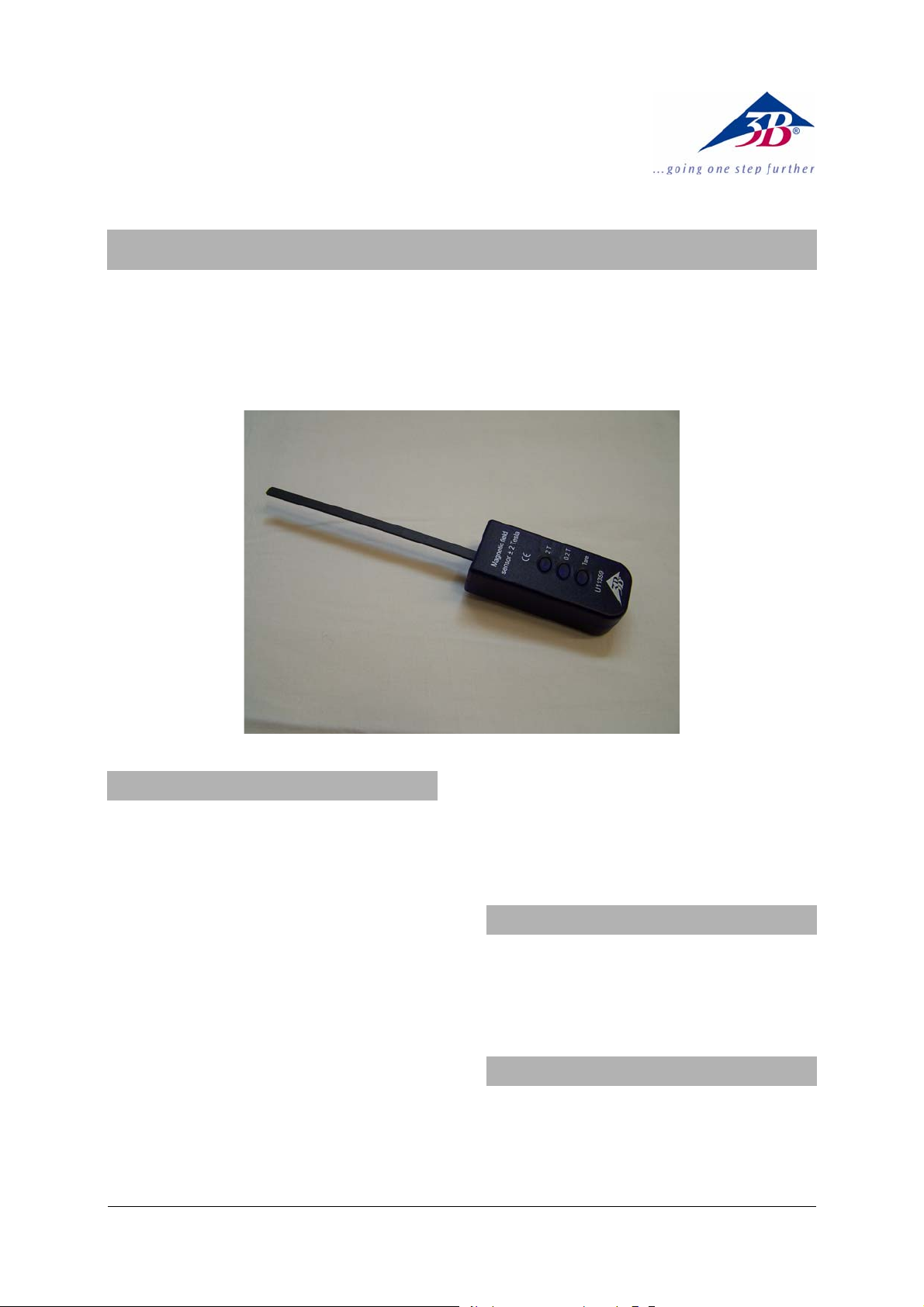
1. Description
Sensor box with attached sensor probe, 140 mm
long, 7 mm wide and 1.9 mm thick, for measuring
magnetic flux density B of a magnetic field acting
outside the box in a tangential plane, primarily for
use with the basic Hall-effect apparatus
(1009934/U8487000).
At the tip of the probe there is a Hall sensor with
an active area of about 0.044 mm², which produces
a steady output signal that is ratiometric (i.e., proportional to the operating voltage).
The Hall sensor has an extended temperature range
of -20°C to +180°C for measuring the flux density of
heated germanium semiconductor crystals (probes).
There are two latching range buttons for 0.2 T and
2 T plus an additional Tare button for calibration.
The current setting of the measurement range is
shown visually by a light-emitting diode on the left
of the relevant button.
The stand clamping rod can be adjusted to hold
the sensor in the desired position and orientation
in the magnetic field that is being measured.
The box is also suitable for use with the connector box
(115 V, 50/60 Hz) (1009954/U8533381-115) or connector box (230 V, 50/60 Hz) (1009955/U8533381-230).
See the relevant technical data.
2. Safety instructions
The magnetic field sensor is not suitable for applications where safety is essential.
• Only use the magnetic field sensor for educa-
tional purposes!
3. Equipment supplied
1 sensor box with permanently attached probe
1 miniDIN 8-pin connecting cable, 60 cm
1 clamping rod, length 120 mm
1 instruction sheet
1
Page 6

4. Technical data
Measurement ranges: 200 mT, 2000 T
Configuration: Tangential
Sensor type: Linear Hall-effect sen-
sor
Position of Hall sensor: 135 mm,
with reference to the
front of the sensor box
casing
Tare range:
200 mT range: +/- 100 mT
2 T range: +/- 1 T
Non-linearity: Max. ±1,5 % of the
total measurement
range
Temperature dependence:
() ( )
⎡
,KBTB
⎢
⎣
T
⎛
⎜
K
⎝
⎤
⎞
−⋅−⋅= 3000008801300
⎟
⎥
⎠
⎦
When used with a connector box
200 mT range: Conversion factor: 125
mT/V, 1.60 V at 200 mT
2 T range: Conversion factor: 1250
mT/V, 1.60 V at 2000 mT
5. Operation
Note:
• To avoid permanent damage to the Hall sensor
in the sensor probe tip, do not subject it to any
mechanical pressure!
• Do not bend the sensor probe tip!
• Hold the sensor box by hand in the magnetic
field to be measured, or use the clamping rod
to position it as required in the experimental
setup.
• Set the tangential orientation of the sensor
element as required and measure the magnetic
field.
• Insert the sensor probe vertically through the
positioning hole marked "MFS" on the top of
the basic Hall-effect apparatus till it comes to
rest. The centre of the active surface on the
sensor will then be within the uniform magnetic field of the electro-magnet and right next
to the semiconductor crystal.
• Read off the value of the magnetic flux density
from the 3B NETlog
The sensor box is automatically detected by the 3B
TM
NETlog
unit.
Any change in the measuring range is automatically transmitted to the 3B NETlog
TM
display.
TM
unit.
5.1 Zero calibration for the sensor box
• When a measuring range has been selected,
hold down the Tare button for about 1 s. Zero
calibration is carried out automatically.
The zero display follows on the 3B NETlog
TM
display
row corresponding to the selected sensor input.
• Under certain circumstances it may be neces-
sary to carry out zero calibration again between measurements.
• Zero calibration should not be carried out
inside the pole pieces of a transformer. The
poles may possess some remanence which
would need to be taken into account.
6. Experimental applications
Magnetic fields of permanent magnets and coils
Hysteresis of transformers
Remanence
Saturation effects in ferrite cores
7. Sample experiment
Experiment to measure magnetic flux density
involving the Hall effect in semiconductors
Equipment needed:
1 3B NETlog
TM
(115 V, 50/60 Hz) 1000539
U11300-115
1 Transformer with Rectifier (115 V, 50/60 Hz)
1003315
U33300-115
1 DC Power Supply 20 V, 5 A (115 V, 50/60 Hz)
1003311
U33020-115
or
1 3B NETlog
TM
(230 V, 50/60 Hz) 1000540
U11300-230
1 Transformer with Rectifier (230 V, 50/60 Hz)
1003316
U33300-230
1 DC Power Supply 20 V, 5 A (230 V, 50/60 Hz)
1003312
U33020-230
1 Hall Effect Basic Apparatus 1009934
U8487000
1 P-Doped Ge on Circuit Board 1009810
U8487020
or
1 N-Doped Ge. on Circuit Board 1009760
U8487030
1 Magnetic Field Sensor ±2000 mT 1009941
U11359
1 U Core 1000979
U8497215
2
Page 7

2 Coils D with 600 Taps 1000988
U8497430
1 Pair of Pole Shoes 1009935
U8497205
1 Set of 15 Safety Experiment Leads 1002843
U138021
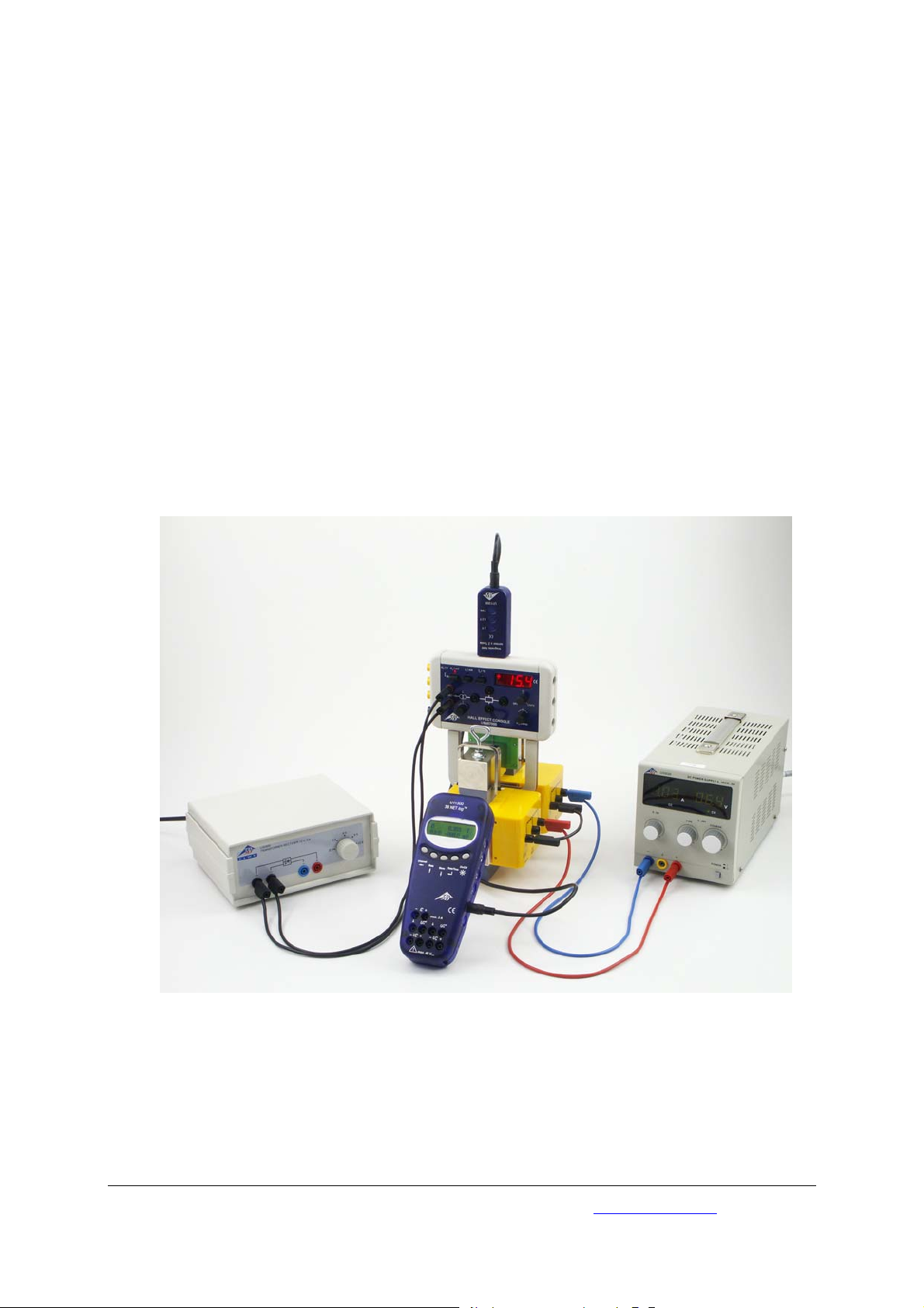
• Set up the experiment as in Fig. 1.
• Switch the transformer and rectifier to the 12-V
setting to supply the basic Hall-effect apparatus with 12 V AC.
• Select the 2-T range on the magnetic field
sensor and press the Tare button.
• Insert the magnetic field sensor into the posi-
tioning hole marked "MFS".
• Set the DC power supply to constant-current
mode, i.e. turn the current-setting potentiometer all the way to the left (0 A) and the voltage-
setting potentiometer all the way to the right
(20 V).
• Increase the current in the series circuit includ-
ing the transformer coils from 0 A to 2 A in
steps of 0.1 A.
• You may also measure the current in the coils
using the current measurement input of the 3B
TM
NETlog
unit (measuring range 2 A DC) and include those measurements in your evaluation
of the experiment.
Example results:
For a pole-piece separation of 8 mm and values of
10.6 V and 1.74 A the flux density will be 300 mT.
Fig. 1 Measurement of flux density in the air gap between pole pieces of an electro-magnet in an experiment set-up using
the basic Hall-effect apparatus
3B Scientific GmbH • Rudorffweg 8 • 21031 Hamburg • Germany • www.3bscientific.com
Subject to technical amendments
© Copyright 2011 3B Scientific GmbH
Page 8

Page 9

3B SCIENTIFIC
Capteur de champ magnétique ±2000 mT
1009941 / U11359
Instructions d'utilisation
10/11 Hh
®
PHYSICS
1. Description
Boîte à capteur avec palpeur de 140 mm de long, 7
mm de large et 1,9 mm d'épaisseur permettant de
mesurer la densité du flux magnétique B d'un champ
magnétique exercé de l'extérieur dans une direction
tangentielle, surtout pour l'appareil de base pour
l'étude de l'effet Hall (1009934 / U8487000).
Capteur Hall disposé sur la pointe du palpeur avec
une surface active d'environ 0,044 mm² à signal de
sortie continu ratiométrique (c'est-à-dire proportionnel à la tension de service).
Plage de température du capteur Hall étendue de 20 °C ... + 180 °C pour mesurer la densité du flux au
niveau des cristaux ge germanium semi-conducteurs
chauffés (essais).
Deux boutons de la gamme 0.2 T et 2 T avec fonction d'enclenchement et un bouton de tare supplémentaire. Signalisation optique du calibre actuel à
l'aide d'une diode lumineuse à gauche de la touche.
Possibilité de fixation sur une barre de support
pour une orientation définie dans le champ
magnétique à mesurer.
Également adapté à l'utilisation d'un boîtier de
connexion (115 V, 50/60 Hz) (1009954 / U8533381-
115) ou d'un boîtier de connexion (230 V, 50/60 Hz)
(1009955 / U8533381-230), se reporter aux caractéristiques techniques.
2. Consignes de sécurité
Le capteur de champ magnétique n'est pas conçu
pour des applications liées à la sécurité !
• N'utilisez le capteur de champ magnétique que
pour la formation.
3. Matériel fourni
1 boîte à capteur avec partie de palpeur fixe
1 câble mini-Din à 8 broches, 60 cm de long
1 barre de support, 120 mm
1 instructions d'utilisation
1
Page 10

4. Caractéristiques techniques
Calibres : 200 mT, 2000 T
Configuration : tangentielle
Type de capteur : capteur à effet Hall
linéaire
Position du capteur Hall : 135 mm,
par rapport à la surface
frontale du boîtier du
capteur
Plage de tare :
dans la gamme 200 mT : +/- 100 mT
dans la gamme 2 mT : +/- 1 T
Non-linéarité : max. ±1,5 % du calibre
Lien avec la température :
() ( )
⎡
,KBTB
⎢
⎣
T
⎛
⎜
K
⎝
⎤
⎞
−⋅−⋅= 3000008801300
⎟
⎥
⎠
⎦
Utilisation avec le boîtier de connexion
dans la gamme 200 mT : Facteur de transfert :
125 mT/V; 1,60 V pour
200 mT
dans la gamme 2 mT : Facteur de transfert :
1250 mT/V; 1,60 V pour
2000 mT
5. Manipulation
Précision :
• Pour éviter des endommagements irréparables
du capteur Hall utilisé dans la pointe du palpeur, n'exposez pas ce dernier à des pressions
mécaniques.
• Ne pliez pas la pointe du palpeur.
• Tenez la boîte à capteur à la main dans le
champ magnétique à mesurer ou, le cas
échéant, fixez-la à la barre de support.
• Observez l'orientation tangentielle de la sonde
et mesurez le champ magnétique.
• Plonger l'élément capteur via l'exécution du
positionnement "MFS" au niveau du bord supérieur de l'appareil de base de l'effet Hall, à
la verticale jusqu'au support mécanique. De
cette façon, le centre de la surface active de l'élément capteur est situé dans le champ homogène de l'électro-aimant et donc en contact
direct avec le cristal semi-conducteur.
• Lire la valeur de la densité du flux magnétique
sur l'écran du 3B NETlog
La boîte à capteurs comprend une fonction de
reconnaissance automatique via le 3B NETlog
Une commutation de la plage de mesure sera reportée sur le 3B NETlog
TM
.
TM
.
TM
.
5.1 Tarage du point zéro de la boîte à capteur
• Dans la plage de mesure sélectionnée, appuyer
sur le bouton de tare (tare) pendant env. 1 s.
Le réglage se fait automatiquement.
L'affichage zéro est actualisé dans la ligne d'affichage de l'entrée du capteur sélectionnée dans le
3B NETlog
• Si nécessaire, il faudra régler le point zéro
TM
.
entre chaque mesure.
• effectuer le réglage du point zéro en-dehors
des cosses d'un transformateur ! Les cosses
possèdent déjà une rémanence qui doit être
prise en compte !
6. Expériences
Champs magnétiques d'aimants permanents et de
bobines
Hystérèse des transformateurs
Rémanence
Effets de saturation à l'intérieur des noyaux de fer
7. Exemple d'expérience
Mesure de la densité du flux magnétique dans l'expérimentation de l'effet Hall de semi-conducteurs
Matériel requis :
1 3B NETlog
TM
(115 V, 50/60 Hz) 1000539
U11300-115
1 Transformateur avec redresseur (115 V, 50/60 Hz)
1003315
U33300-115
1 Alimentation CC 20 V, 5 A (115 V, 50/60 Hz)
1003311
U33020-115
ou
1 3B NETlog
TM
(230 V, 50/60 Hz) 1000540
U11300-230
1 Transformateur avec redresseur (230 V, 50/60 Hz)
1003316
U33300-230
1 Alimentation CC 20 V, 5 A (230 V, 50/60 Hz)
1003312
U33020-230
1 Appareil de base à effet Hall 1009934
U8487000
1 Ge dopé p sur plaque à circuit imprimé 1009810
U8487020
ou
1 Ge dopé n sur plaque à circuit imprimé 1009760
U8487030
1 Capteur de champ mag. ±2000 mT 1009941
U11359
1 Noyau en U 1000979
U8497215
2
Page 11
2 Bobines D à 600 spires 1000988
U8497430
1 Paire de cosses et étrier élastique 1009935
U8497205
1 Jeu de 15 cordons de sécurité 1002843
U138021
• Monter l'expérimentation comme sur la fig. 1
• Brancher le transformateur avec redresseur sur
du 12 V et alimenter l'appareil de base à effet
Hall avec une tension alternative de 12 V.
• Sur le capteur de champ magnétique, sélec-
tionner la plage de mesure 2 T et actionner le
bouton de tare.
• Insérer le capteur de champ magnétique dans
la position "MFS".
• Régler l'alimentation CC sur un foncitonne-
ment avec courant constant, c'est à dire : potentiomètre du variateur d'intensité sur la bu-
tée gauche (0 A), potentiomètre du variateur de
tension sur la butée droite (20 V).
• Augmenter progressivement l'intensité du
branchement en série des bobines du transformateur de 0 A à 2 A.
• Le cas échéant, définir l'intensité des bobines
via l'entrée de mesure de l'intensité du 3B
TM
NETlog
(plage de mesure de 2 A CC)) et inclure
les valeurs de mesure dans l'évaluation de
l'expérience.
Résultat type :
Pour une distance de 8 mm entre les cosses et des
valeurs situées entre 10.6 V et 1.74 A, on atteint
une densité de flux de 300 mT.
Fig. 1 Mesure de la densité du flux dans la couche d'air entre les cosses d'un électro-aimant dans le montage expérimental
de l'appareil de base à effet Hall
3B Scientific GmbH • Rudorffweg 8 • 21031 Hamburg • Allemagne • www.3bscientific.com
Sous réserve de modifications techniques
© Copyright 2011 3B Scientific GmbH
Page 12

Page 13

3B SCIENTIFIC
Sensore campo magnetico ±2000 mT
1009941 / U11359
Istruzioni per l'uso
10/11 Hh
®
PHYSICS
1. Descrizione
Scatola del sensore con sonda applicata lunga 140
mm, larga 7 mm e spessa 1,9 mm per la misurazione della densità di flusso magnetico B di un campo magnetico agente dall'esterno in direzione
tangenziale, prevalentemente per l'apparecchio di
base per effetto Hall (1009934 / U8487000).
Sensore Hall situato sulla punta della sonda con
una superficie attiva di circa 0,044 mm² con segnale di uscita radiometrico costante (ovvero proporzionale alla tensione di esercizio).
Vasto range di temperatura del sensore Hall da - 20
°C a + 180 °C per la misurazione della densità di
flusso su cristalli semiconduttori di germanio riscaldati (campioni).
Due tasti di regolazione dell'intervallo con 0,2 T e 2 T
con funzione a scatto e tasto di tara supplementare.
Display ottico del range di misura attualmente attivato con un diodo luminoso a sinistra del tasto.
Possibilità di fissaggio al supporto dello stativo per
l'orientamento definito nel campo magnetico da
misurare.
Adatto anche per l'impiego con la scatola di connessione (115 V, 50/60 Hz) (1009954 / U8533381-
115) o la scatola di connessione (230 V, 50/60 Hz)
(1009955 / U8533381-230); vedere in proposito
anche le Caratteristiche Tecniche.
2. Norme di sicurezza
Il sensore di campo magnetico non è adatto ad
applicazioni importanti per la sicurezza!
• Utilizzare il sensore di campo magnetico solo
per scopi formativi!
3. Fornitura
1 Scatola del sensore parte della sonda applicata
fissa
1 Cavo di collegamento miniDIN da 8 pin, lungh.
60 cm
1 Supporto stativo, lungh. 120 mm
1 Manuale d'istruzioni
1
Page 14

4. Dati tecnici
Range di misura: 200 mT, 2000 T
Configurazione: tangenziale
Tipo sensore: sensore a effetto Hall
lineare
Posizione del sensore Hall: 135 mm,
riferita alla parte frontale dell'alloggiamento
della scatola del sensore
Range tara:
nel range 200 mT: +/- 100 mT
nel range 2 T: +/- 1 T
Non linearità: max. ± 1,5% del range
di misura totale
Dipendenza della temperatura:
() ( )
⎡
,KBTB
⎢
⎣
T
⎛
⎜
K
⎝
⎤
⎞
−⋅−⋅= 3000008801300
⎟
⎥
⎠
⎦
Uso con scatola di connessione
nel range 200 mT: Fattore di trasmissione:
125 mT/V; 1,60 V a 200
mT
nel range 2 T: Fattore di trasmissione:
1250 mT/V; 1,60 V a
2000 mT
5. Utilizzo
Nota:
• Per evitare danni permanenti al sensore Hall
inserito nella punta della sonda, non sottoporlo a pressioni da compressione meccaniche!
• Non piegare la punta della sonda!
• Tenere manualmente la scatola del sensore nel
campo magnetico da misurare oppure prendere l'asta dello stativo e fissarlo alla struttura
dell'esperimento.
• Fare attenzione all'orientamento tangenziale
del sensore e misurare il campo magnetico.
• Immergere il sensore tramite la bussola di posizi-
onamento "MFS", situata sul bordo superiore
dell'apparecchio di base per effetto Hall, in senso
verticale fino all'appoggio meccanico. Il centro
della superficie attiva del sensore si trova nel
campo omogeneo dell'elettromagnete e direttamente sul cristallo semiconduttore.
• Il display del 3B NETlog
TM
indicherà il valore
della densità di flusso magnetico.
La scatola del sensore viene riconosciuta automaticamente dal 3B NETlog
La commutazione del range di misura viene trasmessa al 3B NETlog
TM
.
TM
.
5.1 Compensazione del punto zero della scatola
del sensore
• Nel range di misura prescelto, tenere premuto
il tasto Tara per circa 1 s. La compensazione
avviene automaticamente.
Nella riga corrispondente all’ingresso selezionato
per il sensore viene eseguito l'aggiornamento
dell'indicazione del 3B NETlog
• Se necessario, ripetere il processo di compen-
TM
.
sazione del punto zero tra le misurazioni.
• Eseguire la compensazione del punto zero
al di fuori delle espansioni polari del trasformatore! Tenere in considerazione che le espansioni polari possono avere una rimanenza!
6. Applicazioni per prove
Campi magnetici di magneti permanenti e bobine
Isteresi di trasformatori
Rimanenza
Effetti di saturazione nell'anima in ferro
7. Esperimento di esempio
Misurazione della densità di flusso magnetico
nell'esperimento per effetto Hall su semiconduttori
Apparecchi necessari:
1 3B NETlog
TM
(115 V, 50/60 Hz) 1000539
U11300-115
1 Trasformatore con raddrizzatore (115 V, 50/60 Hz)
1003315
U33300-115
1 Alimentatore CC 20 V, 5 A (115 V, 50/60 Hz)
1003311
U33020-115
oppure
1 3B NETlog
TM
(230 V, 50/60 Hz) 1000540
U11300-230
1 Trasformatore con raddrizzatore (230 V, 50/60 Hz)
1003316
U33300-230
1 Alimentatore CC 20 V, 5 A (230 V, 50/60 Hz)
1003312
U33020-230
1 Apparecchio di base per effetto Hall 1009934
U8487000
1 p-Ge su circuito stampato 1009810
U8487020
oppure
1 n-Ge su circuito stampato 1009760
U8487030
1 Sensore campo mag. ±2000 mT 1009941
U11359
1 Nucleo a U 1000979
U8497215
2
Page 15

2 Bobine D con 600 spire 1000988
U8497430
1 Coppia di espansioni polari 1009935
U8497205
1 Set di 15 cavi di sicurezza p. esperi. 1002843
U138021
• Eseguire la disposizione sperimentale secondo
Fig. 1.
• Impostare il trasformatore con raddrizzatore a 12
V e alimentare l'apparecchio di base per effetto
Hall con una tensione alternata pari a 12 V.
• Selezionare sul sensore di campo magnetico il
range di misura 2 T e premere il tasto Tara.
• Portare il sensore di campo magnetico nella
bussola di posizionamento "MFS".
• Impostare l'alimentatore CC sul funzionamento
a corrente costante, vale a dire: potenziometro/regolatore di corrente sulla battuta
sinistra (0 A), potenziometro/regolatore di tensione sulla battuta destra (20 V).
• Aumentare la corrente nel collegamento in
serie delle bobine del trasformatore da 0 A fino
a 2 A a passi da 0,1 A.
• Condurre eventualmente la corrente di bobina
attraverso l'ingresso di misura della corrente
del 3B NETlog
TM
(range di misura 2 A CC) e integrare i valori di misurazione nella valutazione
dell'esperimento.
Risultato esempio:
In presenza di una distanza tra le espansioni polari
pari a 8 mm e con valori 10,6 V e 1,74 A, si raggiunge una densità di flusso di 300 mT.
Fig. 1 Misurazione della densità di flusso nel traferro fra le espansioni polari di un elettromagnete nella struttura speri-
mentale relativa all'apparecchio di base per effetto Hall
3B Scientific GmbH • Rudorffweg 8 • 21031 Amburgo • Germania • www.3bscientific.com
Con riserva di modifiche tecniche
© Copyright 2011 3B Scientific GmbH
Page 16

Page 17

3B SCIENTIFIC
Sensor de campo magnético ±2000 mT
1009941 / U11359
Instrucciones de uso
10/11 Hh
®
PHYSICS
1. Descripción
Caja de sensor con parte de sonda de 140 mm de
largo, 7 mm de ancho y 1,9 mm adosada
lateralmente, para la medición de densidades de
flujo magnético B de un campo magnético que actua
externamente en dirección tangencial,
especialmente para el aparato básico del efecto Hall
(1009934 / U8487000).
Sensor de Hall de una superficie activa; de aprox.
0,044 mm² colocado en la punta de la sonda y de
una señal de salida radiométrica constante (es decir,
proporcional a la tensión de trabajo)
Alcance de temperaturas ampliado del sensor de Hall,
de - 20 °C ... + 180 °C para la medición de densidades
de campo magnético en cristales de Germanio
recalentados (Muestras).
Dos teclas de alcances de medida con 0,2 T y 2 T, con
función de enclavamiento y una tecla adicional de
tara. Indicación óptica del alcance de medida activo,
por medio de LED a la izquierda la tecla.
Con posibilidad de ser fijado con varilla soporte para una
orientación definida en el campo magnético a medir.
Tambien apropiado para funcionar con la caja de
conexión (115 V, 50/60 Hz) (1009954 / U8533381-115)
resp. la caja de conexión (230 V, 50/60 Hz) (1009955 /
U8533381-230); véanse, para ello, los datos técnicos.
2. Advertencias de seguridad
¡El sensor de campo magnético no es apropiado para
aplicaciones de relevantes para seguridad!
• ¡Utilizar el sensor de campo magnético sólo para
objetivos didácticos!
3. Volumen de entrega
1 Caja de sensor parte de sonda adosada fijamente
1 Cable de conexión miniDIN de 8 pines, 60 cm de
largo
1 Varilla soporte, 120 mm de largo
1 Instrucciones de uso
1
Page 18

4. Datos técnicos
Alcances de medida: 200 mT, 2000 T
Configuración: tangencial
Tipo de sensor: Sensor lineal de efecto
Hall
Posición del sensor de Hall: 135 mm, con respecto a
la superficie frontal de la
carcasa del sensor
Alcance de tara:
en el alcance de 200 mT: +/- 100 mT
en el alcance de 2 T: +/- 1 T
No linealidad: max. ± 1,5 % del fondo
del alcance de medida
Dependencia con la temperatura:
() ( )
⎡
,KBTB
⎢
⎣
T
⎛
⎜
K
⎝
⎤
⎞
−⋅−⋅= 3000008801300
⎟
⎥
⎠
⎦
Aplicación con la caja de conexión
en el alcance de 200 mT: Relación de trasferencia:
125 mT/V; 1,60 V con 200
mT
en el alcance de 2 T: Relación de trasferencia:
1250 mT/V; 1,60 V con
2000 mT
5. Manejo
Observación:
• Para evitar daños permanentes del sensor de
Hall que se encuentra en la punta de la sonda,
¡No se debe hacer a ninguna clase de presión
mecánica sobre la misma!
• ¡La punta del sensor no se debe doblar!
• La caja de sensor se sostiene manualmente en
campo magnético a medir o en caso necesario se
provee de una varilla soporte para acercarla al
montaje de experimentación.
• Se tiene en cuenta la orientación tangencial del
elemento sensorial y se mide así el campo
magnético.
• Se inserta perpendicularmente el elemento sensor,
hasta el asiento mecánico, a través del orificio de
posicionamiento ”MFS” que se encuentra en el
borde superior del aparato básico del efecto Hall. En
esta forma el centro de la sección activa del
elemento sensor se encuentra en el campo
homogéneo del electroimán y directamente al lado
del cristal semicondutor.
• En el display del 3B NETlog
TM
se lee el valor de la
densidad de campo magnético.
La caja del sensor está dotada de un reconocimiento
automático por medio del 3B NETlog
Una conmutación del alcance de medida se trasmite
directamente al 3B NETlog
TM
.
TM
.
5.1 Compensación del punto cero de la caja de
sensor
• Estando en el alcance de medida elegido se pulsa
la tecla de tara (Tare) aprox. 1 s. La compensaciónn se hace entonces automáticamente.
Se realiza una actualización de la indicación de cero
en las líneas del display del 3B NETlog
TM
de la
entrada de sensor elegida.
• Si es necesario se repite el proceso de
compensación de cero entre las diferentes
mediciones.
• ¡La compensación del punto cero se realiza fuera
del espacio entre las piezas polares de un
transformador! ¡Las piezas pueden tener ya una
remanencia, la cual es necesario tener en
cuenta!
6. Aplicaciones experimentales
Campos magnéticos de imanes permanentes y de
bobinas
Histeresis transformadores
Remanencia
Efectos de saturación en núcleos de hierro
7. Ejemplos experimentales
Medición de la densidad del flujo magnético en el
experimento del efecto Hall en semiconductores
Aparatos necesarios:
1 3B NETlog
TM
(115 V, 50/60 Hz) 1000539
U11300-115
1 Transformador con rectificador (115 V, 50/60 Hz)
1003315
U33300-115
1 Fuente de alimentación CC 20 V (115 V, 50/60 Hz)
1003311
U33020-115
ó
1 3B NETlog
TM
(230 V, 50/60 Hz) 1000540
U11300-230
1 Transformador con rectificador (230 V, 50/60 Hz)
1003316
U33300-230
1 Fuente de alimentación CC 20 V (230 V, 50/60 Hz)
1003312
U33020-230
1 Aparato básico del efecto Hall 1009934
U8487000
1 p-Ge sobre placa de circuito impreso 1009810
U8487020
ó
1 n-Ge sobe placa de circuito impreso 1009760
U8487030
2
Page 19

1 Sensor de campo mag. ±2000 mT 1009941
U11359
1 Núcleo en U 1000979
U8497215
2 Bobinas D con 600 espiras 1000988
U8497430
1 Par de piezas polares y arco tensor 1009935
U8497205
1 Juego de 15 cables 1002843
U138021
• Se monta el experimento de acuerdo con la Fig.
1.
• Se conecta el transformador a 12 V por medio
del rectificador y se alimenta el aparato básico
del efecto Hall con 12 V de tensión alterna.
• Se ajusta el sensor de campo magnétio en el alcance
de medida de 2 T y se pulsa la tecla de tara.
• Se desliza el sensor de campo magnético en el
orificio de posicionamiento ”MFS”.
• La fuente de alimentación de CC se ajusta en el
modo de corriente constante, es decir: El
potenciómetro de ajuste de corriente se lleva al
extremo izquierdo (0 A),el potenciómetro de
ajuste tensión se lleva al extremo derecho (20 V).
• La corriente en la conexión en serie de las
bobinas del transformador se aumenta de 0 A
hasta 2 A en pasos de 0,1 A.
• Si es necesario se pasa la corriente de las
bobinas a través de la entrada de corriente del
3B NETlog
TM
(Alcance de medida 2 A CC) y se
consideran los valores de medida en la
evaluación del experimento.
Resultado ejemplar:
Con una distancia entre las piezas polares de 8 mm y
con los valores de 10,6 V para la tensión y 1,74 A
para la corriente se logra una densidad de flujo
magnético de 300 mT.
Fig. 1 Medición de la densidad de flujo magnético en la ranura de aire entre las piezas polares de un electroimán en el
montaje experimental para el aparato básico del efecto Hall
3B Scientific GmbH • Rudorffweg 8 • 21031 Hamburgo • Alemania • www.3bscientific.com
Se reservan las modificaciones técnicas
© Copyright 2011 3B Scientific GmbH
Page 20

Page 21

3B SCIENTIFIC
Sensor de campo magnético ±2000 mT
1009941 / U11359
Manual de instruções
10/11 Hh
®
PHYSICS
1. Descrição
Sensorbox com elemento sensor integrado de 140
mm de comprimento, 7 mm de largura e elemento
sensor de 1,9 mm de espessura para a medição da
densidade de fluxo magnético B um campo
magnético agindo exteriormente em direção
tangencial, sobre tudo para o aparelho base do
efeito de Hall (1009934 / U8487000).
O sensor Hall que se encontra na ponta do sensor
com uma superfície ativa de aprox. 0,044 mm² com
sinal de saída radiométrico constante (ou seja,
proporcional à tensão).
Faixa de temperatura expandida do sensor Hall de 20 °C ... + 180 °C para medição da densidade de
fluxo em cristais semicondutores de germânio
aquecidos (amostra).
Duas teclas de faixa com 0,2 T e 2 T com função de
fecho e uma tecla adicional de tara. Indicação ótica
da faixa de medição atualmente utilizada por meio
de díodo luminoso.
Possibilidade de fixação na vara do pé de apoio
para uma orientação definida no campo magnético
a ser medido.
Também é adequado para ser operado com a caixa
de conexão (115 V, 50/60 Hz) (1009954 / U8533381-
115), respectivamente, a caixa de conexão (230 V,
50/60 Hz) (1009955 / U8533381-230); para isto
consultar os dados técnicos.
2. Indicações de segurança
O sensor de campo magnético não é adequado
para as utilizações relevantes à segurança!
• Utilizar o sensor de campo magnético somente
para fins didáticos!
3. Fornecimento
1 sensorbox com elemento sensor integrado fixo
1 cabo de conexão mini DIN de 8-pinos, 60 cm de
comprimento
1 vara de pé de apoio, 120 mm de comprimento
1 manual de instruções
1
Page 22

4. Dados técnicos
Faixas de medição: 200 mT, 2000 T
Configuração: tangencial
Tipo de sensor: sensor linear de efeito
Hall
Posição do sensor Hall: 135 mm,
relativo à superfície
frontal da armação do
sensor Box
Faixa de tara:
Na faixa de 200 mT: +/- 100 mT
Na faixa de 2 T: +/- 1 T
Alinhamento: máx. ± 1,5 % da faixa
de medição total
Dependência de temperatura:
() ( )
⎡
,KBTB
⎢
⎣
T
⎛
⎜
K
⎝
⎤
⎞
−⋅−⋅= 3000008801300
⎟
⎥
⎠
⎦
Utilização com a caixa de conexão
Na faixa de 200 mT: Fator de transmissão:
125 mT/V; 1,60 V em
200 mT
Na faixa de 2 T: Fator de transmissão:
1250 mT/V; 1,60 V em
2000 mT
5. Utilização
Indicação:
• Para evitar danos permanentes no sensor Hall
integrado na ponta do sensor, nunca expô-lo a
esforço mecânico!
• Não dobrar a ponta do sensor!
• Segurar o Sensorbox com a mão dentro do
campo magnético a ser medido ou conforme o
caso, instalar a vara do pé de apoio e fixar na
montagem experimental.
• Levar em conta a orientação tangencial do
elemento sensor e medir o campo magnético.
• Inserir o elemento de sensor verticalmente no
conduto de posicionamento "MFS" do canto
superior no aparelho base de efeito Hall até o
suporte mecânico. Nisto o centro da superfície
ativa do elemento de sensor encontra-se no
campo homogêneo do eletroímã e diretamente
no cristal semicondutor.
• Ler no display do 3B NETlog
TM
o valor da
densidade de fluxo magnético.
O sensor Box tem um reconhecimento automático
através do 3B NETlog
Uma comutação da faixa de medição é transmitida
ao 3B NETlog
TM
TM
.
.
5.1 Sensorbox de ajuste de ponto zero
• Na faixa de medição selecionada apertar a
tecla (tara) por aprox. 1 s. O alinhamento
acontece automaticamente.
Acontece uma atualização da indicação do zero na
linha de display do NETlog
TM
da entrada de sensor
selecionada.
• Quando necessário, o processo de balance do
ponto zero entre as medições terá que ser
repetido.
• Efetuar o balance de zero fora das sapatas
polares de um transformador! As sapatas
polares já possuem eventualmente uma
remanência, que deve ser tomada em conta!
6. Utilizações experimentais
Campos magnéticos de ímãs permanentes e de
bobinas
Histerese de transformadores
Remanência
Efeitos de saturação em núcleos de ferro
7. Exemplos de experiências
Messung der magnetischen Flussdichte im Experiment zum Hall-Effekt an Halbleitern
Aparelhos necessários:
1 3B NETlog
TM
(115 V, 50/60 Hz) 1000539
U11300-115
1 Transformador com retificador (115 V, 50/60 Hz)
1003315
U33300-115
1 Fonte de alimentação DC 20 V (115 V, 50/60 Hz)
1003311
U33020-115
ou
1 3B NETlog
TM
(230 V, 50/60 Hz) 1000540
U11300-230
1 Transformador com retificador (230 V, 50/60 Hz)
1003316
U33300-230
1 Fonte de alimentação DC 20 V (230 V, 50/60 Hz)
1003312
U33020-230
1 Aparelho básico para efeito Hall 1009934
U8487000
1 Ge dopado tipo p sobre placa cond. 1009810
U8487020
ou
1 Ge dopado tipo n sobre placa cond. 1009760
U8487030
1 Sensor de campo mag. ±2000 mT 1009941
U11359
2
Page 23

1 Núcleo em U 1000979
U8497215
2 Bobinas D com 600 espiras 1000988
U8497430
1 Par de sapatas polares e tensores 1009935
U8497205
1 Conjunto de 15 cabos 1002843
U138021
• Montar a experiência segundo Fig. 1.
• Comutar o transformador com retificador para
12 V e alimentar o aparelho base de efeito Hall
com 12 V de tensão alternada.
• Escolher no sensor de campo magnético a faixa
de medição 2 T e acionar a tecla de tara.
• Inserir o sensor de campo magnético pelo
condutor de posicionamento "MFS".
• Ajustar a fonte de alimentação DC para operação
de corrente constante, é dizer: o potenciômetro
comutador da corrente no encosto da esquerda
(0 A), o potenciômetro comutador de tensão no
encosto da direita (20 V).
• Aumentar a corrente no circuito em série das
bobinas de transformador de 0 A até 2 A em
passos de 0,1 A.
• Eventualmente conduzir a corrente das
bobinas sobre a entrada de medição de
corrente do 3B NETlog
TM
(Faixa de medição 2 A
DC)) e incluir os valores de medição na
avaliação da experiência.
Resultado de exemplo:
Num espaçamento de sapatas polares de 8 mm e
os valores de 10,6 V e 1,74 A se obtém uma
densidade de fluxo de 300 mT.
Fig. 1 Medição da densidade de fluxo no entreferro entre as sapatas polares de um eletro-ímã na montagem de experiên-
cia no aparelho base para o efeito de Hall
3B Scientific GmbH • Rudorffweg 8 • 21031 Hamburgo • Alemanha • www.3bscientific.com
Sob reserva de alterações técnicas
© Copyright 2011 3B Scientific GmbH
Page 24

 Loading...