

Page 1

2N OfficeRoute
USER MANUAL
version 1.3
www.2n.cz
1
Page 2

2N OfficeRoute
Dear customer,
let us congratulate you on having purchased the 2N
OfficeRoute system. This new product has been
developed and produced in order to provide the
maximum utility value, quality and reliability to the
user. We hope you will be fully satisfied with the 2N
OfficeRoute for a long time.
• The manufacturer constantly improves the software
contained in the product (the so-called firmware). The
technology used therein helps you download the latest
firmware version to the 2N OfficeRoute using an
ordinary PC anytime. For the latest firmware version see
www.2n.cz. We recommend you to apply the latest
version to avoid problems that have already been
eliminated.
• You also find the latest version of the User Manual at
www.2n.cz.
• Check your delivery for completeness according to the
packing list and study this manual carefully before
installing this product. The manufacturer shall not be
responsible for damage caused by any use of this product
in contradiction with the User Manual. The warranty
terms and conditions do not apply to damage incurred as
a result of gross handling and/or undue storing of the
product or violation of the technical parameters included
herein.
• This manual is very much detailed and includes
subsections that are irrelevant for the basic installation
purposes as well as subsections referring to other 2N
OfficeRoute models. Therefore, pay attention to hints
informing you which subsections are necessary for you
and which are not.
www.2n.cz
2
Page 3

2N OfficeRoute
Item Pieces
1 Packing List
Please check your 2N OfficeRoute delivery for
completeness with the following packing list.
2N OfficeRoute – check the model type according to
the order number, see the type label on the gateway
back side
12V/2,5 A mains adapter 1
USB cable 1
ETHERNET cabel 1
Antenna 1
Wall mounting holder 1
Dowels 2
Screws 2
1
Quick user guide 1
Warranty certificate 1
Compliance certificate 1
2N product CD 1
www.2n.cz
3
Page 4

2N OfficeRoute
CONTENTS
1 PACKING LIST ................................................................................................. 3
2 PRODUCT PRESENTATION .............................................................................. 5
2.1 HOW TO SAVE TELEPHONE COSTS.................................................................... 5
2.2 OTHER ADVANTAGES AND APPLICATIONS .......................................................... 6
2.3 RF RADIATION SAFETY PRECAUTIONS ............................................................... 6
3 INSTALLATION ............................................................................................... 7
3.1 BEFORE INSTALLATION .................................................................................. 8
3.2 BRIEF INSTALLATION GUIDE ...........................................................................10
3.3 PROPER MOUNTING....................................................................................11
3.4 LAN CONNECTION ......................................................................................13
3.5 ANTENNA CONNECTION ...............................................................................13
3.6 GATEWAY POWER SUPPLY ............................................................................14
3.7 SIM CARD INSERTION ..................................................................................15
3.8 PC CONNECTION ........................................................................................15
3.9 STATUS INDICATORS ....................................................................................16
3.9.1 Power Indicator .............................................................................16
3.9.2 GSM Indicators ..............................................................................17
3.10 CONSOLE ACCESS .......................................................................................18
3.10.1 Serial console access ......................................................................18
3.10.2 Submenus ......................................................................................19
3.10.3 Commands and Values ..................................................................19
3.10.4 About Menus… ..............................................................................20
3.10.5 Telnet console access .....................................................................21
3.11 WEB BROWSER ACCESS ...............................................................................22
3.11.1 Survey of Group Bookmarks and Menus .........................................23
4 NETWORK SETTINGS .....................................................................................24
5 USER MANAGEMENT ....................................................................................26
6 TELEPHONY SERVICES ...................................................................................28
7 ADMINISTRATION .........................................................................................35
8 STATES&LOGS ...............................................................................................36
9 MESSAGING ..................................................................................................36
10 TECHNICAL PARAMETERS .............................................................................39
www.2n.cz
4
Page 5

2N OfficeRoute
2 Product presentation
The 2N OfficeRoute gateways provide direct
interconnection of VoIP, GSM and UMTS networks
with the support of SIP signalling protocol.
The voice mode, i.e. an outgoing or incoming call, is
the basic function of the system. The gateway is
equipped with all functions necessary for such use
and provides a very high comfort in this mode.
The data mode, i.e. HSPA/EDGE/GPRS data router,
gives a possibility to use 2N OfficeRoute as a router,
firewall and DNS proxy. It also has a DHCP server
functionality. There is also very unique feature –
VRRP+ (virtual router redundancy protocol) so it
can serve as a back-up route of your internet
connectivity.
In addition to voice transmission, 2N OfficeRoute can
send and receive short text messages. It is giving
you an option to integrate SMS functionality to you
email client (i.e. MS Outlook).
2N OfficeRoute contains an inbuilt SIP proxy server
and can thus serve as an IP PBX for SIP telephones.
No extra equipment (an external GSM telephone, etc.)
is needed for normal operation. All programmable
parameters are default-preset in such a manner that
you can commence your telephone traffic the
moment you connect the Ethernet and supply cables,
antenna and SIM card and set the IP parameters.
2.1 How to Save Telephone Costs
You are advised to use the most advantageous tariff
of your GSM provider for your UMTS/GSM calls.
You can bar selected numbers or groups of numbers in
your gateway. You shall pay nothing for the calls
you have barred.
2N OfficeRoute keeps detailed records on all calls.
This helps you find out easily why your bill is
higher than it should be.
The Least Cost Router is flexible enough to help you
set rules for GSM/UMTS/SIP calling at the lowest
possible operation costs.
www.2n.cz
5
Page 6

2N OfficeRoute
2.2 Other Advantages and Applications
2N OfficeRoute integrates the best of all
communication technologies.
With the aid of a built-in SIP proxy server you can
create a complete VoIP network without
additional third party products' costs.
The intelligent routing of incoming calls accelerates
the connection of incoming calls and makes calling
more comfortable.
An easily recordable DISA voice message function is
available.
You can use the conditioned or unconditioned call
forwarding function.
You won’t loose any call with internal voicemail and
Mobility Extension features.
Unlike mobile telephones, this system does not expose
you to the RF electromagnetic field while making
calls.
2.3 RF Radiation Safety Precautions
! It is prohibited to use any transmitters, including
UMTS/GSM devices, in areas where explosives are
used, such as quarries.
! A GSM/UMTS devices may affect sensitive life-
saving devices in medical centres.
! In general, any prohibition regarding mobile phones
based on RF energy radiation applies to GSM/UMTS
devices.
! Where necessary, a 2N OfficeRoute may be installed
at a safe distance (in the neighbouring building, e.g.)
and an Ethernet cable may be carried from the device
gateway to the original building.
! Although 2N OfficeRoute is not intended for
aeroplanes, all relevant prohibitions and regulations
regarding mobile phones apply to them here.
www.2n.cz
6
Page 7

2N OfficeRoute
3 Installation
This section shows how to install the 2N OfficeRoute
gateway including all accessories.
Here is a survey of what you will find in this section:
What you should know before you start;
Overview of installation steps;
How to choose the right place;
Connection to PC network;
Antenna connection;
Supply mains adapter connection;
SIM card replacement;
PC connection with a USB;
How to read LED statuses.
www.2n.cz
7
Page 8
2N OfficeRoute
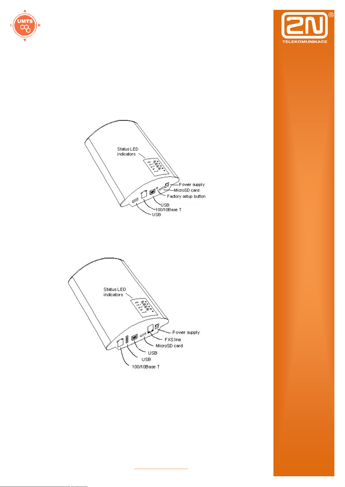
3.1 Before Installation
Before you start installing your 2N OfficeRoute, get
familiar with its physical structure, arrangement of
connectors and status indicators.
Fig. 1 – Bottom View
www.2n.cz
8
Page 9
2N OfficeRoute
Fig. 2 – Top View
www.2n.cz
9
Page 10

2N OfficeRoute
3.2 Brief Installation Guide
Proper mounting – 2N OfficeRoute is designed for
suspension on a vertical surface. Fit the holder
included in the delivery on a wall and hang the
gateway on it. For details on the prescribed working
position and other recommendations refer to
Subsection 1.
Cable connection – connect the gateway using a
patch-cable to the LAN (Local Area Network). For
details on proper wiring refer to Subsection.
Antenna connection – connect an internal antenna or
an external antenna cable to the SMA antenna
connector. Place the external antenna on a place
with a good UMTS/GSM signal (refer to
Subsection).
Gateway power supply – the delivery includes a
mains adapter. Plug in the adapter connector into the
gateway and the power adapter into a mains socket
(≈230V/50Hz). The gateway turns on immediately
(see Subsection).
SIM card insertion – SIM cards are inserted in
holders on the gateway top.
PC connection and initial configuration – a web
browser is used for gateway configuration in normal
operation. If you have not defined the IP address for
the gateway, use the USB cable included in the
delivery for initial configuration of the basic
parameters or reach OfficeRoute on its default IP
address 10.0.0.1.
Setting and monitoring – Having set the basic
network parameters (IP address, etc.), you can
configure OfficeRoute using a standard web browser
(http or https). Configuration options and essential
procedures shall be discussed in detail in respective
sections.
www.2n.cz
10
Page 11

2N OfficeRoute
3.3 Proper Mounting
The device is designed for mounting on a vertical
surface. For this purpose a wall mounting holder is
available. Just fit the holder with dowels and screws
to the wall and hang the device.
Fig. 3 – Gateway Holder Wall-Mounting
Fig. 4 – Gateway Holder-Hanging
It is possible to operate this device in another working
position (e.g. on a desk) for a short time only, for
example in servicing centres for quick testing
purposes.
The allowed working temperature and relative
humidity ranges are included in Section bellow.
Exceeding the recommended operating temperature
values need not affect the gateway function
immediately but may result in more rapid ageing and
lower reliability.
The device is intended for indoor use. It may not be
exposed to rain, flowing water, condensed moisture,
fog, or mist.
www.2n.cz
11
Page 12

2N OfficeRoute
The device may not be exposed to aggressive gas, acid
vapours, solvents, etc. or aggressive liquids, during
cover cleaning, for example.
The device is not designed for high-vibration
environments, e.g. means of transport, machine
rooms, etc.
Free space has to be left under and over the device for
cables and agitated air to remove operational heat.
Install the device on a place with a good UMTS/GSM
signal.
A misplacement of the GSM/UMTS device or its
antenna near television, broadcasting or similar RFsensitive devices may exercise an adverse effect
upon their function.
Being a source of RF energy emission, the device
antenna should not be located close to human
bodies. The hazard is higher than with mobile
telephones because the device is usually used by
many people and thus employed more often.
www.2n.cz
12
Page 13

2N OfficeRoute
3.4 LAN Connection
2N OfficeRoute is connected to the 10/100BASE-T
(Twisted Pair Ethernet) LAN using a standard straight
(non-crossed) cable terminated with RJ-45 connectors
like other types of equipment (PC, etc.).
Fig. 5 – LAN Connection
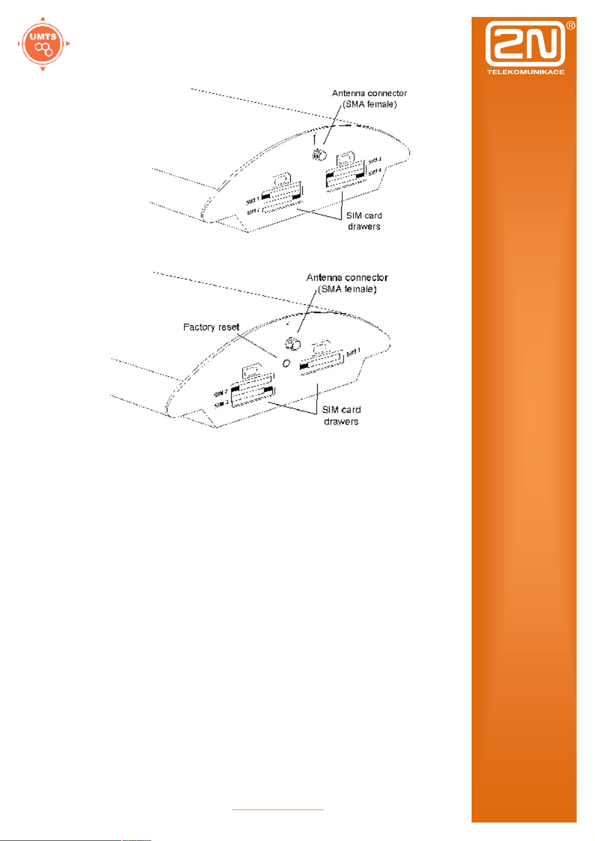
3.5 Antenna Connection
No matter if equipped with one UMTS and one, two ot
three GSM modules, it has just one SMA antenna
connector, to which an external antenna cable is
connected. This external antenna should be installed
vertically on a place with a good UMTS/GSM signal.
Fig. 6 – Antenna Connector Connection
Tighten the antenna connector gently with your hand,
never use a wrench!
www.2n.cz
13
Page 14

2N OfficeRoute
3.6 Gateway Power Supply
Be sure to use only the mains supply adapter that is
included in this device delivery.
Before plugging in the device, make sure that the
mains voltage value meets the data given on the
mains adapter label.
Furthermore, make sure that the antenna has been
connected. If you connect the device to the power
supply without an antenna, the UMTS/GSM module
transmitter might get damaged.
Now plug the supply adapter into a mains socket and
connect the adapter connector to the device,. The
status indicators indicate the proper operation. For
their meanings refer to a Subsection.
Fig. 7 – Supply Adapter Connection
www.2n.cz
14
Page 15

2N OfficeRoute
3.7 SIM Card Insertion
To insert your SIM card in the device, press the yellow
button on the appropriate card drawer with a suitable
tool to make the drawer slide out a little. Remove the
drawer, insert the SIM card and replace the drawer. You
can not replace SIM cards even with your device on.
Fig. 8 – SIM Card Inserting Procedure
3.8 PC Connection
You need direct interconnection of your 2N
OfficeRoute gateway and PC especially when you do
not know the gateway IP address and thus cannot
configure it using a web browser. In such a case,
connect the gateway directly to your PC USB port with
the cable enclosed and select the basic network
parameters using your console interface.
You can control the console interface with any terminalemulating program according to the VT-100
specification at least. The Microsoft Windows OS, e.g.,
contains a communication tool HyperTerminal, which
can be used for this purpose.
By default, the gateway serial port communication
parameters are set at 921,600 bits per second, 8 data
bits, no parity, 1 stop bit, no flow control. Set the
communication program on the PC side identically.
www.2n.cz
15
Page 16

2N OfficeRoute
Indicator (blue)
3.9 Status Indicators
There is a panel with five LEDs on the gateway upper
cover. The Power indicator signals that the gateway as
a whole is in operation. The other LEDs, marked CH 1
to CH 4, indicate the status of each module.
3.9.1 Power Indicator
Basic diagnostic tests are performed automatically
whenever the gateway is connected to supply voltage.
Each test step is signalled by a specific colour
combination of the LEDs. The testing process is usually
shorter than 0.5 sec and so it looks like a quick
sequence of LED flashes at first sight. If, however, a
test step fails, the indicator combination related to the
failed test remains lighted. This provides a convenient
troubleshooting tool to the technical support personnel.
After all hardware tests have been completed
successfully, the operating system kernel is loaded.
During the process, all module indicators are off and the
blue continuous Power light blinks with the period of
approximately 1 second.
When the operating system kernel has been loaded, the
blue Power indicator keeps shining continuously.
In exceptional cases, when a fatal failure of software
occurs and the gateway stops working, the Power
indicator starts flashing quickly. All you can do is
disconnect the gateway from the power supply for a few
seconds and restart it.
Power
No light The system is not working.
Blinking The system kernel is being loaded.
Continuous light The system is working.
Quick flashing Fatal failure
www.2n.cz
16
Page 17

2N OfficeRoute
GSM Indicators
3.9.2 GSM Indicators
The CH 2 to CH 4 indicators signal the status of the
respective GSM module. After connection to the power
supply, the VoIP gateway application starts within two
minutes. During that time, the installed GSM modules
and SIM cards are detected. If a GSM module or SIM
card is not detected, the respective indicator remains
off.
If they are detected, the process of module and SIM
card initialisation is commenced. The respective
indicator shines red during the process. If the process is
unsuccessful, the LED goes off. If the indicator turns
orange, it means that the module has not logged-in to
any GSM network.
If the LED is green, you can make calls and send SMS
via the respective module.
The respective module LED blinks green quickly during
call establishing. When the connection has been built
successfully, the indicator remains green during the
whole call.
No light The module is ready
Red light SIM card initialisation in progress or
no SIM card is in the drawer.
Yellow/Orange light The SIM is not logged-in to any
GSM network.
Quick green blinking A call is being established (dialled).
Green light A call is being made.
www.2n.cz
17
Page 18

2N OfficeRoute
3.10 Console Access
The console system is arranged as a set of nested
menus. By selecting a menu item you either get into a
submenu, or have the required operation executed, or
set the selected parameter.
3.10.1 Serial console access
When the gateway is powered on, the main menu
should get displayed after terminal connection.
When you’re entering an the main menu, press for
to appear.
OfficeRoute V2-2-0 Main Menu
OfficeRoute
Option Value Description
1 – Configuration [ menu ] – General configuration
2 – Set Admin password – Set administration password
3 – Help – Display help for serial
console settings
Enter an option number, <ESC> previous menu
>
Every menu consists of the following parts:
Header: Contains (from the left): the product name,
firmware version, menu name and network name
assigned to the equipment.
Options column: Displays numbers and names of
available options.
Value column: If "[menu]" is displayed, the item
includes a submenu. Otherwise it shows the actual
value of the option.
Description column: Explains briefly the meaning of
every option in the menu.
„Enter an option number…>“: Here enter the option
number.
To select an option from a menu, enter its first number
and press for confirmation.
www.2n.cz
18
Page 19

2N OfficeRoute
3.10.2 Submenus
If you select a submenu, this submenu gets displayed.
Now you can select items from the selected submenu or
return by pressing .
3.10.3 Commands and Values
If you are requested to enter some information after
selecting an item, you should enter one of the following
values:
Key word: A list of one or more fixed strings. To
select one, enter only so many initial characters as
can differ it unambiguously from other key words.
Enter one of [ansi,color,teletype] : a
In the above mentioned case, select a key word by
entering just an "a", "c", or "t"“ and press .
String: an arbitrary number of characters. The
acceptable value interval may be included in the
prompt.
Enter a hostname from 1 to 32 characters:
OfficeRoute
Integer: A decadic integral number. The acceptable
value interval may be included in the prompt.
Enter a size between 1 and 100 : 99
A hexadecimal integral number – number to be
entered in the hexadecimal format using characters
0÷9 and a÷f or A÷F.
Enter a hex number between 1h and ffh : 1a
MAC address: up to 12 hexadecimal digits of the
physical address. Zeros at the beginning can be
omitted.
Enter the remote network address :
50C229C4E2
IP address: an Internet address in the format of four
digits of 0÷255 separated with dots.
Enter an IP address : 192.168.22.30
www.2n.cz
19
Page 20

2N OfficeRoute
As soon as the requested information is entered, the
respective operation is executed, new values are
displayed in the redrawn menu.
Some configuration parameters may have just one of
two constant values. By selecting such an item you
immediately make its value opposite to that preceding
the selection. Typical examples are on and off
parameters. If their value is on, then it becomes off
when the item is selected and vice versa.
Some commands execute operations that have a serious
impact on the behaviour of the entire system (such as
restart). Therefore, the system usually "makes sure"
before execution whether it is really your intention.
Are you sure [y/n] :
If you give an answer other than "y" or "Y", the
command will not be executed.
To cancel the command execution and quit the prompt
press the key any time.
3.10.4 About Menus…
We shall discuss the serial console menus in detail in
sections devoted to gateway parameter settings. Below
is a brief survey of these menus only.
Main menu: Appears after the USB cable is connected
to the terminal (sometimes you must press Enter).
Configuration menu: Contains six submenus: network
configuration, serial console settings, command line,
states, reboot and settings.
Network configuration: Used for setting the gateway
IP address, network mask, initial router, DNS addresses,
network name and domain.
Serial console configuration: Helps set the terminal
type and change the initial serial link parameters –
transition rate, data and stop bits, parity and flow
control type.
Command line: Allows you to set/change basic
telephony settings – lcr, routes, sip, devices, calls, disa.
States: There are states of devices (strength of signal,
register status, etc.) and calls.
Reboot: This option restarts the device.
Settings: DHCP and VRRP server settings.
www.2n.cz
20
Page 21

2N OfficeRoute
3.10.5 Telnet console access
This is a short description of new features added to the
serial console configuration. For the standard serial
console configuration capabilities refer to the 2N
OfficeRoute
There is also a possibility of using Telnet for 2N
OfficeRoute configuration in addition to the standard
serial console configuration. Connect to your
OfficeRoute via Telnet (type telnet <your OfficeRoute
IP address> in command line). If successful,
OfficeRoute will require an authentization from you. To
log in, use valid login and password of one of
OfficeRoute’s users who is in Administrators group. No
user other than user from Administrators group will be
logged in. If login and password entered correctly, you
will be logged in.
Now you will see the window similar to the standard
serial console configuratoin window and you can work
with it in the same way. To log out Telnet
configuration, get to the main menu and choose Logout
option (this option is not visible in the serial console
window).
There are all menus available as by USB access.
www.2n.cz
21
Page 22

2N OfficeRoute
3.11 Web Browser Access
While the serial console interface enables you to change
the basic gateway parameters only, the web browser
gives you access to all parameter settings and services
available in the OfficeRoute gateway. To establish
connection with the gateway, enter the gateway IP
address into the Internet address setting line in the
browser, e.g.:
http://10.0.0.1
If you have connected all parts properly and set the
correct gateway and PC IP addresses, the request to
enter the access user name and password should get
displayed.
The manufacturer supplies the gateways with a
predefined default user account Admin without having
set its default password. Mind the Upper/Lower Case
while entering the user name and password! The first
thing you should do for safety reasons after putting your
gateway in operation is to change the administrator
password.
Fig. 9 – Web Administration Login Page
www.2n.cz
22
Page 23

2N OfficeRoute
After a successful login you get onto the main page of
the web application. The window is divided into four
parts,.
Fig. 10 – Web Interface Desktop
Header bar: Network, User management, Telephony
services, Administration, States&logs and Messaging.
Above the header bar are bookmarks which help you
select the user relation language and displays the
currently logged-in user.
Group menu: There is a group menu for each selection
from Header bar on the left side. The bookmark settings
are arranged in two menu levels. By selecting a Level 1
item you display the respective Level 2 subitems. If the
Level 1 item contains no more subitems or if you select
a subitem, the appropriate application form gets
displayed on the remaining window space.
3.11.1 Survey of Group Bookmarks and Menus
Network: IP address settings, DHCP server settings,
Firewall settings, NATP settings, DNS proxy settings
and HSPA/EDGE/GPRS data settings.
User management: User groups and user (extension)
management.
www.2n.cz
23
Page 24

2N OfficeRoute
Telephony services: Devices (SIP, H.323, DISA lines)
management, GSM incoming routing settings
(Operator/DISA), LCR settings.
Administration: Main settings, Time and Timezone
settings, Firmware upgrade, Licence upload,
Configuration back-up/restore.
States&Logs: States of Devices and calls, Logs for
debugging/troubleshooting, CDR.
SMS: SMS delivery settings (web and SMTP/POP3),
SMS sending web portal.
There is just basic survey of menus. Individual types of
forms, their meanings and options will be discussed
later.
4 Network settings
Main settings: OfficeRoute’s own IP address, mask,
default gateway and DNS. There is also a possibility to
switch on DHCP client (when OfficeRoute doesn’t
serve as a DHCP server and there is another DHCP
server in the network). It is also possible to set Main
settings via serial console or via telnet console.
Filtering: Settings of embedded firewall. It is possible
to set rule for accepting/baring according type of traffic,
source or destination IP address or port.
Port mapping: NATP setting for access devices in an
internal LAN via UMTS network (public IP must be
assigned to OfficeRoute by an operator).
DHCP server: Settings for DHCP server in case that
OfficeRoute serves as LAN DHCP server.
www.2n.cz
24
Page 25

2N OfficeRoute
Fig. 11 – DHCP server settings form
Lease time: validity of a leased IP address
Start address: start of an IP addresses pool
End address: end of an IP addresses pool
Subnet option: Subnet mask for internal network
Router option: Default gateway of subnet (typically it is
IP address of the OfficeRoute, for VRRP it is IP address
of the virtual router.
Primary and Secondary DNS: Used only in case of local
DNS servers in the LAN.
DNS proxy: Serves for caching DNS records in case
that OfficeRoute works as an UMTS router.
VRRP: Settings for Virtual Router Redundancy
Protocol (Described in other part of this manual).
www.2n.cz
25
Page 26

2N OfficeRoute
5 User management
Users: List of all users, Add/Remove user. User is
either extension or user allowed to send SMSes.
Fig. 13 – List of available users
There are 2 default users: Admin and vbegw.
Admin is default user and it is not possible to remove
him. Mainly serves for management of the device.
Emergency change of Admin’s password – connect
OfficeRoute via USB cable and by serial console
change Admin’s password (it is not necessary to know
previous password.
Vbegw is default user for internal SIP line (explanation
of internal SIP line is further in this manual).
Groups: Settings of user’s rights.
Fig. 12 – List of available groups
Administrators is group with all rights enabled.
Add group: A new group adding
www.2n.cz
26
Page 27

2N OfficeRoute
Fig. 13 – ‘Add group’ form
By ticking checkboxes assign rights.
Add user: Adding of a new user/extension
Fig. 16 – ‘Add user’ form
User name: User name for log-in to OfficeRoute’s web
interface and SIP authentication.
New password: Password for log-in and SIP
authentication.
Group: Select group of the user
Default application: Webpage/Form after logging into
OfficeRoute’s web interface.
Rights/Rights denied: Select rights or left empty – rights
are assigned by group selection except SMS rights.
Line number: In case that user is both – extension and
user, Line number is UID (number of extension/SIP
name)
Mobility extension: It is discussed further. In case you
need to set Mobility Extension for this user, tick
Outgoing/Incoming ME checkbox and fill his mobile
phone number.
www.2n.cz
27
Page 28

2N OfficeRoute
Voicemail: It is discussed later. Set PIN for entering
user’s voicemail and set his mobile phone number for
receiving notification SMSes.
6 Telephony services
Devices: List of SIP lines (SIP trunks), SIM cards
(available in the unit or presented in the past) and DISA
lines. DISA line can be standard welcome message or
customized welcome message, voicemail system and
basic IVR.
Fig. 14 – List of available SIM cards
Modification of SIM card’s parameters:
There is a checkbox ‘Present’ at the top of the form
which indicates whether SIM is present in the tray at the
moment. It is highly recommended to power unit off
when you plug/unplug SIM.
Bellow this checkbox are information abour SIM’s
serial number (IMSI), operator’s network code and
name.
There is also possible to fill ‘USSD code for credit’
check for prepaid SIM cards. If you fill proper USSD
code and SIM card is prepaid, you can obtain
information about credit by clicking to ‘Get credit’ in
the SIM cards list.
For sending SMSes is necessary to fill proper ‘Service
centre number’.
In order to be able to use SIM for data/internet
connection (for GPRS/EDGE/UMTS/HSPA) is
necessary to set following parameters – ‘GPRS provider
name’ (it can be any random name) and ‘APN (GPRS
access point)’. Other parameters depend on a specific
www.2n.cz
28
Page 29

2N OfficeRoute
network provider – you can find these information on a
webpage of a network provider or obtain from his
helpline.
Fig. 15 – Modify SIM card form
LCR: Least Cost Router is ‘the brain’ of OfficeRoute.
All rules for call routing (inbound and outbound) can be
set there.
www.2n.cz
29
Page 30

2N OfficeRoute
Fig. 169 – List of LCR rules
LCR menu contains Time intervals (for using time
conditions), Normalization (for incoming/outgoing
number normalization), Tariffication (for setting free
minutes, free SMS, etc.), Blacklist, Routes (a Route is
outgoing direction/trunk consisting of GSM/UMTS
module(s), SIM card(s), SIP line(s) or DISA line).
Main window shows list of LCR rules (used prefixes
and routes).
Time intervals – There is a possibility to define time
interval (condition) for using certain LCR Route.
Default Time intervals are ‘Weekdays’, ‘Weekend’,
‘Workdays’. It is also possible to define certain Time
range.
Normalization – This menu item is used when certain
dialed numbers should be modified.
Example:
Fig. 17 – ‘Add normalization’ form
If dialed number is 0737555666, all LCR rules are
applied and before it is sent to selected LCR route, 0 is
removed (prefix is removed automatically) and +420 is
www.2n.cz
30
Page 31

2N OfficeRoute
added. Remove count is number of removed digits
behind prefix. Final normalized number in this case is
+420737555666.
It is also possible to modify number before LCR rules
are applied (Type is ‘Called incoming’) or modify
calling party number.
Tariffication – possibility to limit SIM card by free
minutes and free SMSes.
Fig. 18 – ‘Add LCR tariff’ form
Tariff name – It’s user defined name for certain tariff.
Line ID – Selected SIM or Line to which tariff is
applied.
Time intervals – Time when tariff is applied.
Restore limit every day - tick when tariff (free minutes)
should be restored every day.
Day of restore call limit – Day in month when tariff
(free minutes) are restored.
Tariffication – settings for counting used
seconds/minutes.
Free minutes, Free SMS – amount of minutes/SMSes to
be used during accounting period (month or day).
www.2n.cz
31
Page 32

2N OfficeRoute
Example on the picture – the tariff is applied to SIM
card 89.......8413, only during weekdays and workdays
(time intervals defined in previous step). Limit is
restored for 1st day in each months (proper time and day
must be set in the unit). Accounting of called minutes is
done following way: when call starts, it charges 60
seconds immediately, when these 60 seconds are spent,
then next 30 seconds are charged. SIM can be used for
300 outgoing minutes and 50 sent SMSes per each
month. When the call limit is exceed, it is not possible
to make an outgoing call.
Routes – List of existing routes and adding and
removing routes. A Route means outgoing trunk (bundle
of SIMs, modules, SIP lines or DISA lines).
Fig. 19 – ‘Add route’ form
There is a route named ‘Mobile Networks’ on the
picture which contains all modules, it is being used
during all defined time intervals without suppressing
CLI (CLI can be suppressed for mobile networks only).
LCR rule – Routing of call is based on the called
number. LCR rule basically defines to which Route
dialed numbers are routed (according prefix).
www.2n.cz
32
Page 33

2N OfficeRoute
Fig. 20 – ‘Add LCR table item’ form
There is an example of a LCR rule. Destination name is
user defined, the rule is applied to called numbers with
prefixes 6 or 7, call is routed to the route ‘ Mobile
networks’ with unknown priority. Priority can be
according free minutes, first free or cycle (for free
minutes and cycle a tariff must be defined for each line
of the route).
LCR test – you can test routing rules after setting all
routing rules and routes. For routing test SIM cards
must be placed in the unit in order to have test fully
functional.
GSM routing – setting of incoming calls routing. The
procedure is follow: at first it is necessary to define
operator’s service and then assign operator’s service to
a module. Operator’s service can be routing to a
www.2n.cz
33
Page 34

2N OfficeRoute
specific number through the specified line (for calls to a
IP phone registered in the internal SIP proxy it is
internal SIP line – in this case is necessary to fill
operator’s number).
SIP PROXY – into the internal SIP proxy IP phones
are registered. SIP proxy serves as a registrar and
location server. For outgoing calls out from SIP proxy
(e.g. to a SIP provider) serves also as a RTP proxy.
Fig. 21 – SIP proxy’s main screen
By SIP proxy routing rules is defined routing (according
the prefix of dialed number). There are 2 rules by
default: all dialed numbers with prefix 0 are routed to
the internal SIP line and the rest is considered as to be
looked up for registered IP phones.
Fig. 22 – ‘Add rule’ for proxy routing form
On the picture: routing is done according prefix, action
might be: ‘connect to LCR’, ‘reject’, ‘change host and
port’ and ‘lookup registration’. By parameter is meant
routing destination of the call. There is a significant
difference against Normalization table – prefix is not
removed in the proxy rule.
Switch SIP Proxy off – proxy may be switched off
when the unit is used as an UMTS router only.
Registration – you can check registered phones here.
www.2n.cz
34
Page 35

2N OfficeRoute
7 Administration
Main configuration: There can be set main parameters
for using the device (e.g. PIN for SIM cards, DSP
codecs – G.729 or G.723, enable Mobility Extension).
Fig. 23 – Administration – Main configuration
Set timezone: setting of timezone where OfficeRoute is
used.
Synchronize time: Synchronization of OfficeRoute’s
time with PC time.
Update firmware: The new firmware can be found on
the webpage www.2n.cz.
Update licence: You can ask for main and additional
licences your distributor/reseller.
Configuration backup: Back-up of whole
configuration (includes the licence and IP address
www.2n.cz
35
Page 36

2N OfficeRoute
setting = when is loaded into a unit, erases the previous
licence and changes IP address of the unit).
SNMP: Setting of SNMP traps sending.
Reboot: Reboot the device. Reboot takes approximately
3 minutes.
8 States&Logs
States: Tariffication – Amount of free minutes/SMSes.
Calls – Information about actual calls.
Devices – Strength of signal, status of registration to
external proxies.
Registrations – Information about registered users.
Call accounting – detailed records of calls to mobile
networks.
Logs – Overview of logs for debugging and
troubleshooting.
Download logs – Possibility to download all logs
zipped into one file. There can be set main parameters
for using the device (e.g. PIN for SIM cards, DSP
codecs – G.729 or G.723, enable Mobility Extension).
9 Messaging
SMS: Sending of SMSes from web interface. Each user
with SMS rights can log in ans send or receive SMSes.
There are 4 folders: Inbox, Sent, To Send, Failed. By
clicking to icon in the right downer corner ‘Create a
new message’ you can create a new SMS message.
SMS delivery: Settings for SMS sending/receiving.
Settings are applied to both web and SMTP/POP3 way
of sending/receiving SMSes.
Settings for SMS sending/receiving via SMTP/POP3
protocols: OfficeRoutes’s internal POP3 server
provides SMS downloading from VBE via e-mail.
Authorization goes through USERNAME and
PASSWORD, which are used for registering to webbased interface of VBE. Each SMS will be changed to
e-mail in the Inbox directory, after successful
www.2n.cz
36
Page 37

2N OfficeRoute
authorization of VBE. There will be SMS sender tel.
number@domain name and SMS receiver tel. number@
domain name (domain name could be set through webbased interface, according to Figure 27 in the header of
e-mail, subject of the message will be filled according
to VBE settings. You can use formatting strings in the
text as well (%n – sender number, %u – receiver
number, %d – date). Message, which is already read,
could be deleted from POP3 server. You can delete the
message from VBE, or mark it as already read (i.e. it is
still available in the Inbox directory through web-based
interface, but POP3 server can not see it, Fig. 27.
Fig. 24 – SMS delivery – Main configuration
OfficeRoute’s internal SMTP server provides sending email messages as SMS from VBE. USERNAME and
www.2n.cz
37
Page 38

2N OfficeRoute
PASSWORD for authorization are the same as the
USERNAME and PASSWORD for web-based interface
of VBE. Authentication could be set in web-based
interface of VBE. Domain name must be equal to POP3
domain name (Fig. 27). Server awaits e-mail in format
Text/Plain, Text/HTML, Multipart/Mixed or
Multipart/Alternative. From the message in format
Text/HTML, only the body of HTML message, without
formatting, is put onto the SMS message. From
messages Multipart/Mixed and Multipart/Alternative
only the first part of message is used, enclosed between
strings, mentioned in the header under name
“boundary“. Server supports the only messages in 7 bit
format in encoding according to ISO-8859-1 or 16 bit
Unicode UTF-8 (messages with the different encoding
could be illegible after receiving message in form of
SMS). SMTP server enables sender IP address control
as well as authentication. With help of web-based
interface, you can enable or disable IP address control
as well as set the list of allowed IP addresses (Fig. 27
and Fig. 28). SMTP server makes one or more SMS
messages from incoming e-mail (maximum number of
created SMS messages is set in web-based interface. It
is possible to set from 0 to 100 messages, Fig. 27) in
form F:<sender><CRLF>S:<e-mail subject (max. 10
characters)><CRLF>e-mail body. Messages with length
of 160 characters are sent subsequently to receiver via
Admin account (already sent SMS messages are
available in SENT directory of user Admin).
Fig. 25 – SMS delivery – SMTP IP access
www.2n.cz
38
Page 39

2N OfficeRoute
VoIP
Mobile networks
Antenna
Power Supply
10 Technical Parameters
Signalling standards SIP
Number of channels 4
Codecs G.711 PCM (64 kbps)
G.729A CS-ACELP (8 kbps)
G.723.1 MP-MLQ/ACELP 6.3 kbps (optional)
PCM quantizing
Mobile network type UMTS WCDMA FDD
SIM cards Plug-in 3V ("small“)
Transmission power 2W (1W)
Receiver sensitivity -95 (-104) dBm
A-law / µ-law
EGSM 900 phase II
GSM 1800 MHz
Frequency UMTS WCDMA FDD 850/1900/2100 MHz
GSM 850/900/1800/1900 MHz
Impedance
Maximum output power 2W
Antenna connector type SMA
50 Ω
Adapter
Supply voltage 12V / 2.5A
Supply connector DC jack, 2.1 mm
Power input max. 20W
230V±10%, 50/60Hz / 12V DC
www.2n.cz
39
Page 40

2N OfficeRoute
Interface
Oper
ational Conditions
Others
USB Connector type A and B, host and master
USB 2.0
Micro SD
Ethernet RJ-45
10/100 Base T
Protocols IP, ICMP, TCP, UDP, DHCP, RTP, TELNET, SSH,
HTTP, HTTPS, SMTP, SNMP, POP3
Temperature
Relative humidity
0°C ÷ 40°C
5 ÷ 90% non-condensing
Dimensions (without
connectors)
CE certification EN 60 950:2000, EN 55 024, EN 55 022 Class B
250×150×50 mm
www.2n.cz
40
 Loading...