

Page 1
www.2n.czVersion
Firmware
2N
®
Helios IP
IP Intercom
Configuration Manual
2.8
2.8.1
Page 2
The 2N TELEKOMUNIKACE a.s. is a Czech manufacturer and supplier of telecommunications
equipment.
The product family developed by 2N TELEKOMUNIKACE a.s. includes GSM gateways, private
branch exchanges (PBX), and door and lift communicators. 2N TELEKOMUNIKACE a.s. has
been ranked among the Czech top companies for years and represented a symbol of
stability and prosperity on the telecommunications market for almost two decades. At
present, we export our products into over 120 countries worldwide and have exclusive
distributors on all continents.
2N is a registered trademark of 2N TELEKOMUNIKACE a.s. Any product and/or other
®
names mentioned herein are registered trademarks and/or trademarks or brands protected
by law.
2N TELEKOMUNIKACE a.s. administers the FAQ database to help you quickly find
information and to answer your questions about 2N products and services. On
www.faq.2n.cz you can find information regarding products adjustment and instructions for
optimum use and procedures „What to do if...“.
2N TELEKOMUNIKACE a.s. hereby declares that the 2N product complies with all
®
Helios IP
basic requirements and other relevant provisions of the 1999/5/EC directive. For the full
wording of the Declaration of Conformity see the CD-ROM (if enclosed) or our website at
www.2n.cz.
This device complies with part 15 of the FCC Rules. Operation is subject to the following
two conditions: (1) This device may not cause harmful interference, and (2) this device
must accept any interference received, including interference that may cause undesired
operation.
The 2N TELEKOMUNIKACE a.s. is the holder of the ISO 9001:2009 certificate. All
development, production and distribution processes of the company are managed by this
standard and guarantee a high quality, technical level and professional aspect of all our
products.
Page 3

Content
1. Product Overview . . . . . . . . . . . . . . . . . . . . . . . . . . . . . . . . . . 4
2. Express Wizard for Basic Settings . . . . . . . . . . . . . . . . . . . . 6
3. Model Differences and Function Licensing . . . . . . . . . . . . . 11
4. Signalling of Operational Statuses . . . . . . . . . . . . . . . . . . . . 14
5. Intercom Configuration . . . . . . . . . . . . . . . . . . . . . . . . . . . . . 16
5.1Status .........................................................19
5.2Directory .......................................................21
5.3Hardware ......................................................33
5.4Services .......................................................60
5.5System ........................................................93
6. Supplementary Information . . . . . . . . . . . . . . . . . . . . . . . . . . 110
6.1Troubleshooting .................................................111
6.2Directives,LawsandRegulations ...................................112
6.3GeneralInstructionsandCautions ...................................114
Page 4

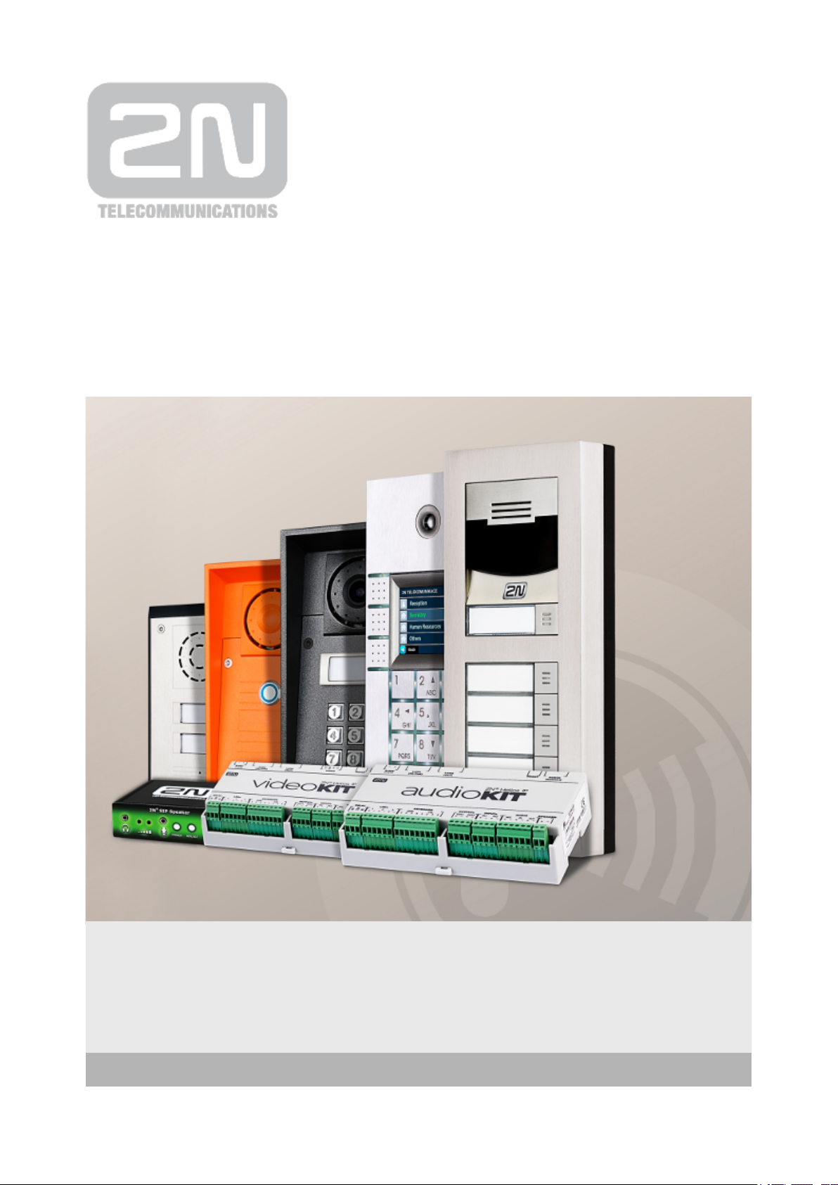
1. Product Overview
The door intercoms can smartly replace traditional doorbell2N Helios IP
®
push-button speakerphone panels and all wiring, bells and home intercom installations
in buildings with structured cabling. The intercoms provide more advanced and wider
services than standard home phones. The installation is very easy, all you need is
connect the intercom to the other LAN elements using a UTP cable and set necessary
parameters.
Thanks to the integrated SIP protocol, the intercom can make use of all VoIP services:
call forwarding at absence (to another office, VoiceMail or a cellular phone) or call
transfer (from the secretary’s office to the required person, e.g.).
The intercoms are equipped with a programmable number of quick dial buttons for
speed calling to the users whose numbers are included in the intercom Phone Book.
Each of the quick dial buttons can be assigned up to three phone numbers, which can
be dialled in parallel or sequentially. Thanks to an integrated time sheet it is possible to
configure each of the buttons in such a way that the called party is always accessible
and/or calls to selected phone numbers can be barred off the working hours.
Some models are equipped with a numeric keypad, which can be used2N Helios IP
®
as a code lock or a standard push-button phone.
The intercoms help LAN users scan the area in front of the camera via 2N Helios IP
®
video streaming. Thanks to the full ONVIF support, the intercoms can become part of
the Video Surveillance System in your facility .
The intercoms can be equipped with an RFID card reader for authorised2N Helios IP
®
access control and thus become a key part of your surveillance or attendance control
systems.
The intercom is equipped with a relay switch (and, optionally, other2N Helios IP
®
relays and outputs), which controls the electric lock or other equipment connected to
the intercom. Its activation time and method can be programmed flexibly: it can be
activated by a code, automatically by a call, by pressing a button, and so on.
The following symbols and pictograms are used in the manual:
®
42N TELEKOMUNIKACE a.s., www.2n.cz
Page 5
Safety
abide by this information to prevent persons from injury.Always
Warning
abide by this information to prevent damage to the device.Always
Caution
Important information for system functionality.
Tip
Useful information for quick and efficient functionality.
Note
Routines or advice for efficient use of the device.
®
52N TELEKOMUNIKACE a.s., www.2n.cz
Page 6

2. Express Wizard for Basic Settings
LAN Connection Setting
You have to know the intercom configuration interface address to connect to the LAN
successfully. Automatic IP address retrieval from the DHCP server is set by default in
the intercoms. Thus, if connected to a network in which a DHCP server2N Helios IP
®
configured to assign IP addresses to all new devices is available, the intercom will
obtain an IP address from the DHCP server. The intercom IP address can be found in
the DHCP server status (according to the MAC address given on the production plate),
or will be communicated to you by the intercom voice function; refer to the Installation
Manual of your intercom model.
If there is no DHCP server in your LAN, use the intercom buttons to set the static IP
address mode, refer to the Installation Manual of your intercom model. Your intercom
address will then be Use it for the first login and then change it if192.168.1.100.
necessary.
Now enter the intercom IP address into your favourite browser. We recommend you to
use the latest Chrome, Firefox or Internet Explorer 9+ versions as is2N Helios IP
®
not fully compatible with earlier browser versions.
Use the name and password (i.e. default reset password) for your first loginadmin 2n
to the configuration interface. We recommend you to change the default password
upon your first login; refer to the parameter in the Password Services / Web Server
menu. Remember the password well or put it down just in case. Because if you forget
the password, you will have to reset the intercom to default values (refer to the
Installation Manual of your intercom model) and lose all your current configuration
changes.
®
62N TELEKOMUNIKACE a.s., www.2n.cz
Page 7
Firmware Update
We also recommend you to update your intercom firmware upon the first login to the
intercom. Refer to for the latest firmware version. Press the www.2n.cz Update
button in the menu to upload firmware. TheFirmware System Maintenance /
intercom will get restarted upon upload and only then the updating process will be
complete. The process takes about 30 seconds.
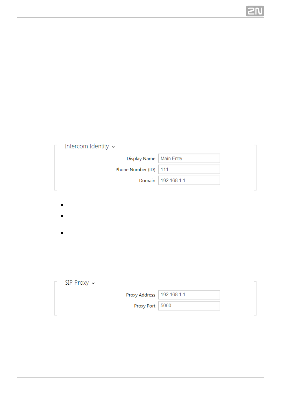
SIP Server Connection Setting
Set the following parameters in the menu to allow yourServices Phone SIP / /
intercom make calls and be accessible within your VoIP infrastructure.
– set the name to be displayed as CLIP on the called party'sDisplay name
phone, in the login window and on the web interface start page.
– set the intercom phone number (or another unique IDPhone number (ID)
composed of characters and digits) to identify the intercom uniquely in calls and
registration.
– set the domain name of the service with which the intercom isDomain
registered. Typically, it is equivalent to the SIP Proxy or Registrar address. If you
do not use a SIP Proxy in your intercom installation, enter the intercom IP
address.
If you use a SIP server (Proxy, Registrar), set the addresses for the following network
elements:
®
72N TELEKOMUNIKACE a.s., www.2n.cz
Page 8
– set the SIP Proxy IP address or domain name.Proxy address
– set the SIP Registrar IP address or domain name. The SIPRegistrar address
Proxy and SIP Registrar addresses are usually identical.
– enable intercom registration with the set SIP Registrar.Registration enabled
If your SIP server requires authentication of terminal equipment, enter the following
parameters:
– enter the password for intercom authentication.Password
Quick Dial Button Settings
All the models are equipped with quick dial buttons. If you press a2N Helios IP
®
quick dial button, a call will be set up to the phone number assigned to the respective
Phone Book position.
Select position 1, which corresponds to quick dial button 1, in the Directory Phone/
menu.Book
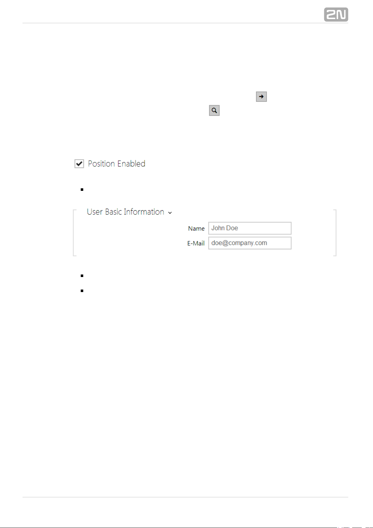
Enable the position in the field and enter the called station phonePosition Enabled
number into the parameter in the section.Phone Number User Phone Numbers
®
82N TELEKOMUNIKACE a.s., www.2n.cz
Page 9
You can also use the intercom with one or more IP phones without a2N Helios IP
®
SIP server. Use the for outgoing calls and enter the called phone SIPDirect SIP Call
address ( ) instead of the phone number.sip:phone_number@phone_ip_address
Electric Lock Switching Settings
An electric lock can be attached to the intercoms and controlled by a2N Helios IP
®
code from the intercom numeric keypad, or a code from the IP phone keypad during a
call. Connect the electric lock as instructed in the Installation Manual of your intercom
model.
®
92N TELEKOMUNIKACE a.s., www.2n.cz
Page 10
Enable the switch in the parameter in the Switch Enabled Hardware Switches / /
tab, set the to the intercom output to which the electric Switch 1 Controlled Output
door lock is connected. Now set one or more activation codes for the electric door lock
switching.
®
102N TELEKOMUNIKACE a.s., www.2n.cz
Page 11
3. Model Differences and Function Licensing
This manual is valid for all members of the family and so some features2N Helios IP
®
described herein are only available in selected models or need to be2N Helios IP
®
activated with a valid licence key. This section provides a short list of differences
between the models and licences which affect the configuration options. If a function is
not available in all the models, there is a note in the respective subsection and
reference to this section.
The table below includes an overview of properties and functions of all the 2N Helios
®
models.IP
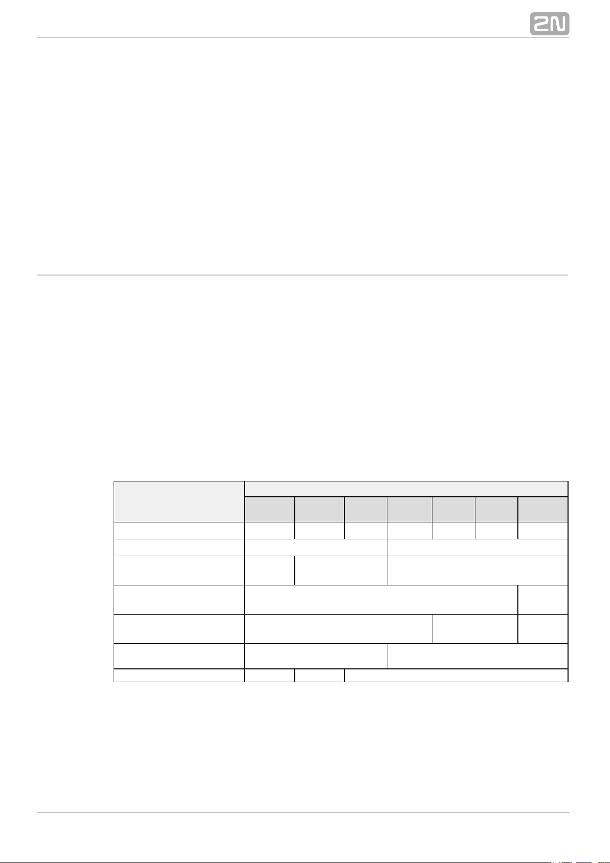
Property/Model
2N Helios IP
®
Verso Vario Force Safety Uni
Audio
Kit
Video
Kit
Part No. 9155… 9137…. 9151… 9152… 9153… 9154… 9154…C
Integrated camera optional ne
Camera resolution
1280 x
960
640 x 480
External analogue
camera support
no yes
External IP camera
support
yes no yes
Internal RFID card
reader
optional no
Display no optional no
®
112N TELEKOMUNIKACE a.s., www.2n.cz
Page 12
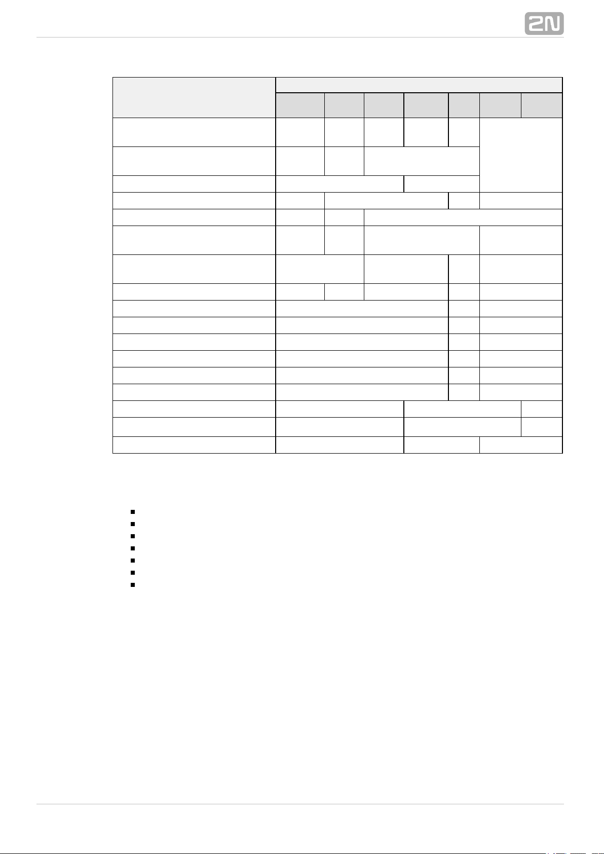
Property/Model
2N Helios IP
®
Verso Vario Force Safety Uni
Audio
Kit
Video
Kit
Basic unit button count 1
1, 3
or 6
1, 2
or 4
1
1 or
2
up to 16
external
programmable
buttons
Button extenders
up to
145
up to
48
no
Numeric keypad optional no
Digital input yes optional no 2
Adaptive volume control yes no yes
Amplifier power output 2 W
150
mW
1 W 10 W
Extended amplifier power
output (10 W)
no yes no no
Tamper switch optional no optional yes no
Phone Book position count 1999 2 16
User deputy yes no yes
User activation/deactivation yes no yes
Controlled switch count 4 1 4
Switch universal code count 10 2 10
User profile count 20 2 20
JPEG HTTP video yes no yes
2N Helios IP Eye® support
yes no yes
Telephone mode yes no yes
Some functions are unavailable until a valid licence key is entered2N Helios IP
®
(refer to the Licence subsection). The following types of licences are available:
Enhanced Audio (Part No. 9137905)
Enhanced Video (Part No. 9137906)
Enhanced Integration (Part No. 9137907)
Enhanced Security (Part No. 9137908)
Gold (Part No. 9137909)
G.729 (Part No. 9137902)
InformaCast (Part No. 9137910)
The G.729 licence allows the audio codec G.729 to be used.
The InformaCast licence allows the SingleWire InformaCast protocol to be used.
No licenced features available for model 2N Helios IP Uni.
@
The table below includes the functions that need to be activated by the licence keys
corresponding to the above mentioned licences. The licences can be combined
arbitrarily.
®
122N TELEKOMUNIKACE a.s., www.2n.cz
Page 13
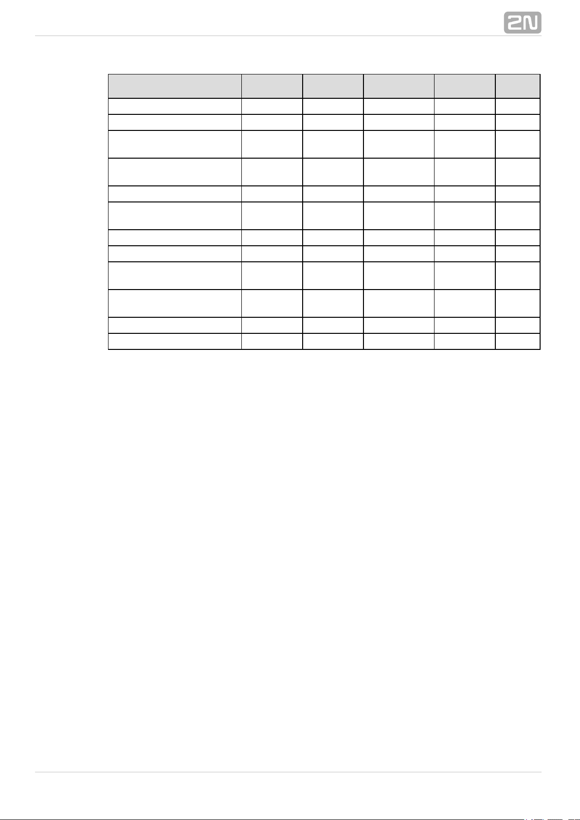
Property/Licence
Enhanced
Audio
Enhanced
Video
Enhanced
Integration
Enhanced
Security
Gold
(Profi)
User sounds • •
Automatic audio test • •
Audio/video streaming
(RTSP Server)
• •
External IP camera
support
• •
ONVIF support • •
Extended switch setting
options
• •
HTTP switch control • •
Automation functions • •
E-mail sending
(SMTP Client)
• •
Automatic update
(TFTP/HTTP Client)
• •
802.1x support • •
SIPS (TLS) support • •
®
132N TELEKOMUNIKACE a.s., www.2n.cz
Page 14
4. Signalling of Operational Statuses
2N Helios IP® generates sounds to signal switching and changes of operational
statuses. Each status change is assigned a different type of tone. See the table below
for the list of signals.
Tone Meaning
User activated
This tone signals entering of the user activation code. The
activation code is used for user (Phone Book position) .activation
Refer to the Phone Book subsection for the activation code
settings.
User deactivated
This tone signals entering of the user deactivation code. The
deactivation code is used for user (Phone Book position) deactiva
tion. A deactivated user may not be called but the call can, if
necessary, be forwarded to a deputy if defined. Refer to the
.Phone Book subsection for the deactivation code settings
Profile activated
This tone signals profile . This function helps enableactivation
alerting of a user group in an office, for example. Refer to the
.Profile subsection for the activation code settings
Profile deactivated
This tone signals profile deactivation. This function helps, for
example, disable alerting of a user group in an office and routing
calls either to a pre-defined phone number (porter's lodge, e.g.)
or user mobile phones. Refer to the Profile subsection for the
.deactivation code settings
Note
Signalling of some of the above mentioned statuses can be modified; refer
to the User Sounds subsection.
®
142N TELEKOMUNIKACE a.s., www.2n.cz
Page 15
Call prolongation confirmation signalling
Calls are time-limited in for security reasons2N Helios IP
®
(protection against blocking). Refer to the Miscellaneous
.subsection for details
Internal application launched
The internal application is launched upon power 2N Helios IP
®
up or restart. A successful launch is signalled by this tone
combination.
Connected to LAN, IP address received
2N Helios IP® logs in upon the internal application launch. A
.successful LAN login is signalled by this tone combination
Disconnected from LAN, IP address lost
This tone signals UTP cable disconnection from .2N Helios IP
®
Disconnection .is signalled by this tone combination
Invalid telephone number or invalid switch activation code
2N Helios IP® allows the user to dial an extension number
directly using the keypad or enter the door unlocking code. An
invalid code is signalled by this tone sequence.
Default reset of network parameters
Upon power up, a 30 s timeout is set for the default reset code
entering. Refer to the Device Configuration subsection in the 2N
Installation Manual for details. Helios IP
®
Call end signalling
2N Helios IP® enables the user to set a call end timeout to
avoid call blocking. Press a key on your VoIP phone to extend the
call time during this timeout.
Connected VoIP phone – 2N Helios IP call
®
This short tone signals successful connection between a VoIP
phone and .2N Helios IP
®
®
152N TELEKOMUNIKACE a.s., www.2n.cz
Page 16
5. Intercom Configuration
®
162N TELEKOMUNIKACE a.s., www.2n.cz
Page 17

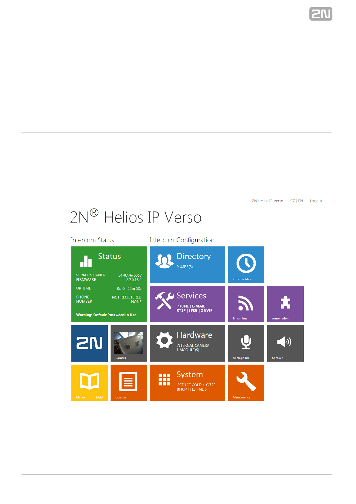
Start Screen
The start screen is an introductory overview screen displayed upon login to the
intercom web interface. Use the back arrow in the left-hand upper corner of the
following web interface pages to return to this screen anytime.
The screen header includes the intercom name (refer to the parameterDisplay Name
in the menu). Select the web interface language with the Services / Phone SIP / CZ
and buttons. Press the button in the right-hand upper corner to log out.EN Log out
The start screen is also the first menu level and quick navigation (click on a tile) to
selected intercom configuration sections. Some tiles also display the state of selected
services.
Configuration Menu
The configuration includes 5 main menus: 2N Helios IP
®
State, Directory,
and including submenus; see below.Hardware, Services System
Status
Device – essentials on the intercom
Services – information on active services and their states
Licence – current states of licences and available intercom functions
Directory
Phone Book – settings for user phone numbers, quick dial buttons, access cards
and switch control user codes
Time Profiles – time profile settings
Access Cards – access card settings
Hardware
Switches – electric lock, lighting, etc. settings
Speaker – audio, signalling, etc. volume control
Microphone – microphone parameters, echo cancelling
Camera – internal camera, external IP camera settings
Keyboard – button and keyboard settings
Display – basic display settings
Card Reader – card reader, Wiegand interface settings
Extenders – extender settings 2N Helios IP Verso
®
®
172N TELEKOMUNIKACE a.s., www.2n.cz
Page 18

Services
Phone – telephone and SIP connection settings
Streaming – audio/video streaming settings (ONVIF, RTSP, Multicast, etc.)
E-Mail – E-mail sending and SMTP connection settings
Automation – flexible intercom settings according to the user's requirements
User Sounds – user sound settings and upload
Web Server – web server and access password settings
Audio Test – automatic audio test settings
System
Network – LAN connection settings, 802.1x, packet capturing
Date and Time – real time and time zone settings
Licence – licence settings, trial licence activation
Certificates – certificate and private key settings
Auto provisioning – automatic firmware and configuration update settings
Syslog – syslog message sending settings
Maintenance – backup and configuration reset, firmware update
®
182N TELEKOMUNIKACE a.s., www.2n.cz
Page 19
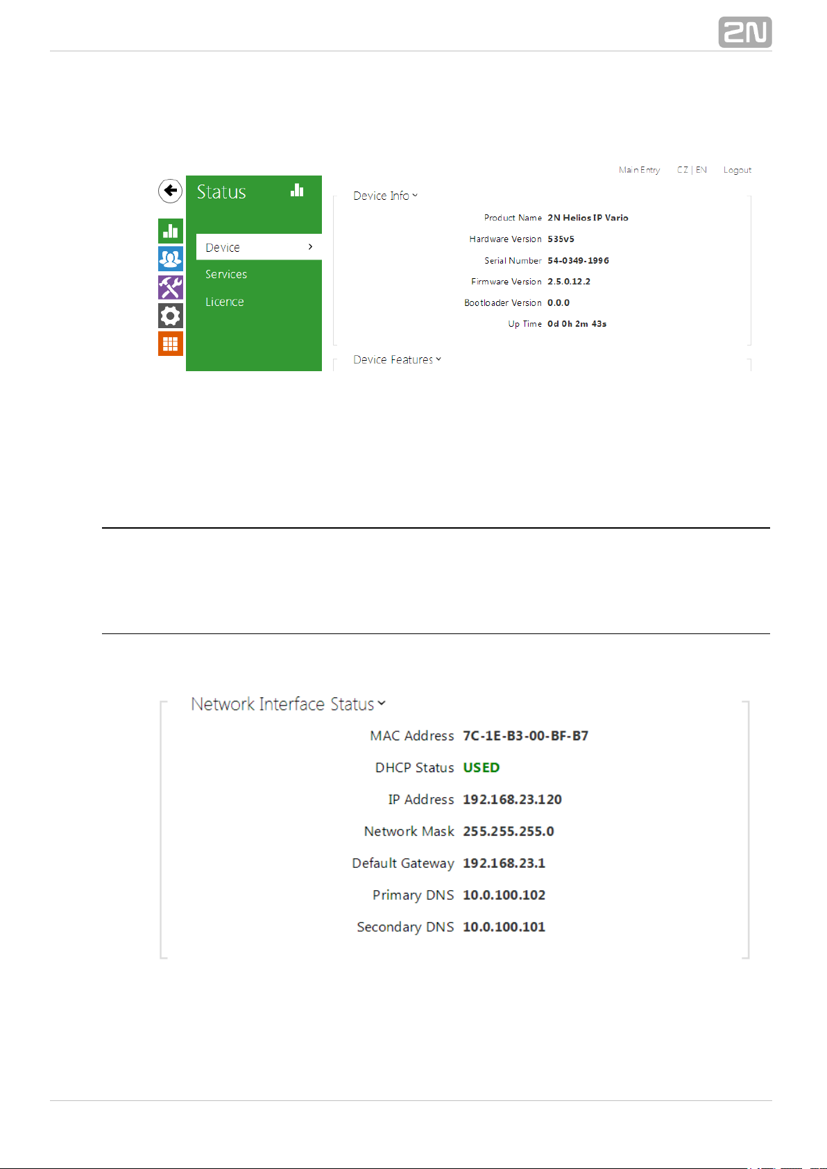
5.1 Status
The menu provides clear status and other essential information on theStatus
intercom. The menu is divided into three tabs: , and .Device Services Licence
Device
The tab displays basic information on the intercom model, its features,Device
firmware and bootloader versions and so on.
Services
The tab displays the status of the network interface and selected services.Services
®
192N TELEKOMUNIKACE a.s., www.2n.cz
Page 20
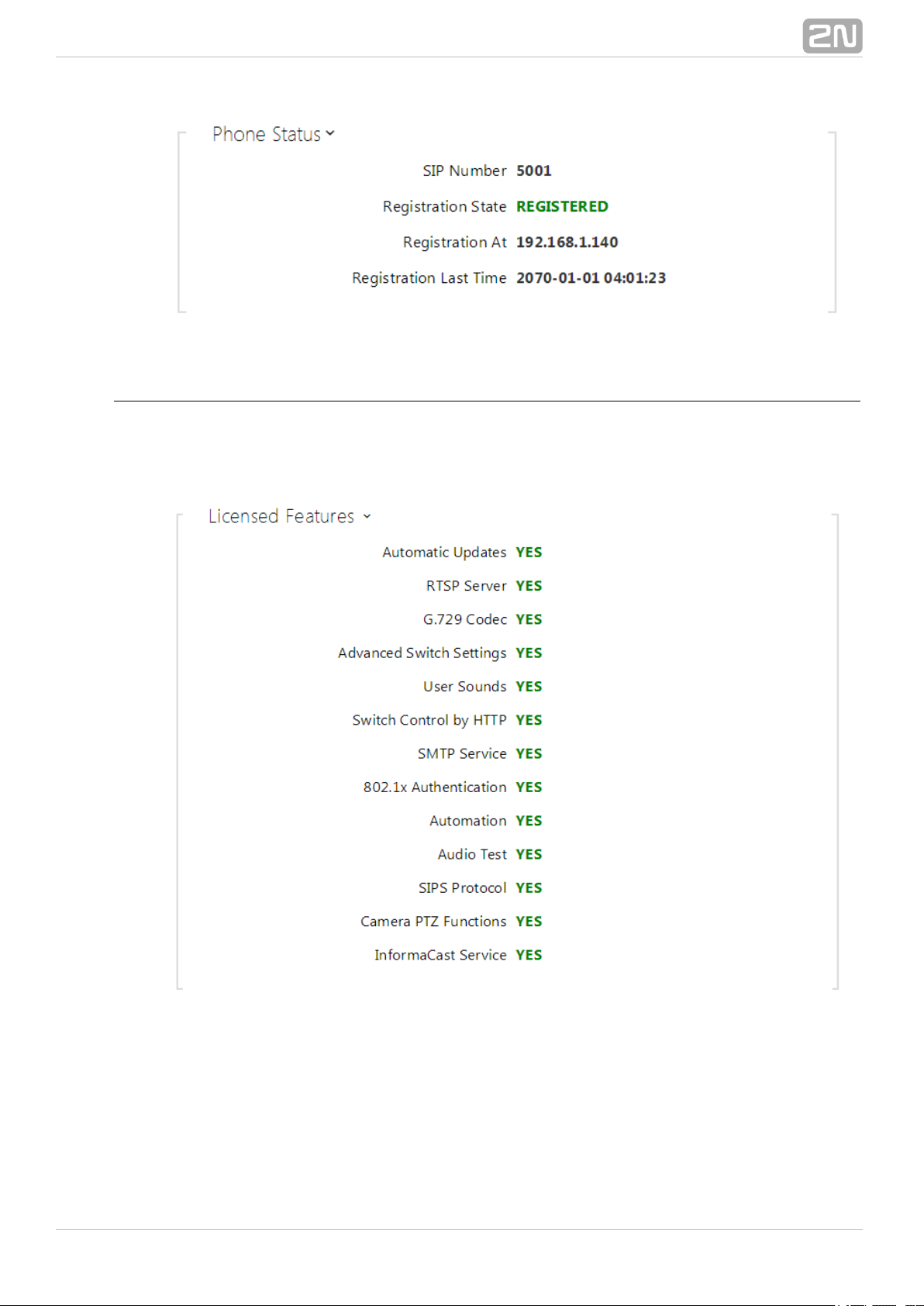
Licence
The tab displays the list of licensed functions of the intercom including their Licence
current availability (on the basis of a valid licence key entered in the System |
menu).Licence
®
202N TELEKOMUNIKACE a.s., www.2n.cz
Page 21

5.2 Directory
Here is what you can find in this subsection:
5.2.1 Phone Book
5.2.2 Time Profiles
5.2.3 Access Cards
®
212N TELEKOMUNIKACE a.s., www.2n.cz
Page 22
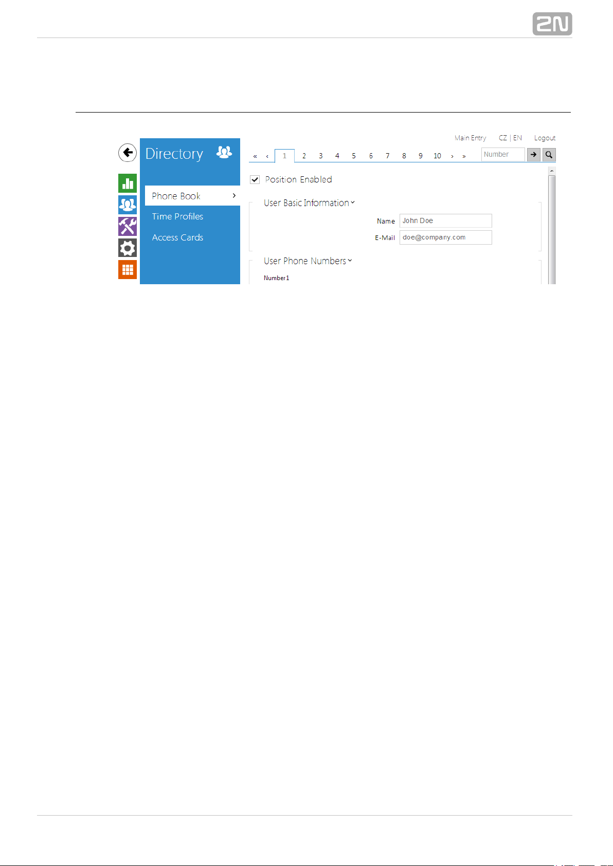
5.2.1 Phone Book
The Phone Book is one of the crucial parts of the intercom configuration. It contains
user information relevant for such intercom functions as quick dialling, RFID card/code
door unlocking, missed call e-mails and so on.
The Phone Book is arranged as a table with up to 1999 positions (depending on the
particular model): typically, each user is assigned just one position.2N Helios IP
®
The Phone Book includes information on the users that are accessible by quick dialling
and users that are only allowed to enter the facility with their RFID cards. As the user
Phone Book position substantially affects the intercom functions, please read the
following text carefully and design the optimum layout according to your needs before
filling the Phone Book with data.
Each intercom user has a specific Phone Book position: 1 through 1999. The user
position number is very important as it also defines the asquick dial button number
signed to the user. Therefore, place the user on the position that corresponds to the
required quick dial button and complete the user phone number to make quick dialling
efficient. Most models are equipped with one or more quick dial2N Helios IP
®
buttons. Refer to the Installation Manual of your intercom model for the button count,
extending options and Phone Book position mapping details.
You are advised to place the users that are not supposed to be assigned any quick dial
button but should have the right to enter the facility with the RFID card or numeric
code onto the top positions of the Phone Book (position 100 and higher). If such user,
for some reason, has to be placed on a position that corresponds to a quick dial button,
leave the user phone number parameter empty and complete the door unlocking RFID
card ID or numeric code only. Thus, you will make the quick dial button act as a
non-programmed key.
In case the number of the users that are to be accessible by the intercom is higher
than the count of the quick dial buttons installed, you can enable user dialling by
entering the Phone Book position via the numeric keypad: the caller dials the position
number and pushes the * key. Enable this using the Dial Users by Phonebook Position
parameter in the menu . If you decide to useHardware / Keyboard / Basic Settings
this user calling method, you are advised to place a clear list of user names and Phone
Book positions including brief instructions near the intercom.
You can also combine quick button dialling and numeric keypad dialling. In this case,
reserve the Phone Book beginning positions for the quick dial buttons and complete the
®
222N TELEKOMUNIKACE a.s., www.2n.cz
Page 23
higher positions (from position 100 up, e.g.) with data on the users to be included in
the public user list. Then select the users to be accessible by quick dialling and copy
their phone numbers to the lower Phone Book positions corresponding to the quick dial
buttons.
Refer to the menu for the Phone Book settings. Use theDirectory / Phone Book
navigation panel for selecting the Phone Book positions easily and arrows for scrolling
pages. Or, you can enter the position number and push to move to the position
quickly. If you know the user's name, push to find its position.
List of Parameters
Position enabled – enable calling to this Phone Book position.
Name – enter the user name for the selected Phone Book position. This
parameter is optional and helps you find items in the Phone Book more easily.
E-mail – enter the user E-mail to which information on missed or successful calls
can be sent. Refer to the E-Mail subsection for more details.
®
232N TELEKOMUNIKACE a.s., www.2n.cz
Page 24

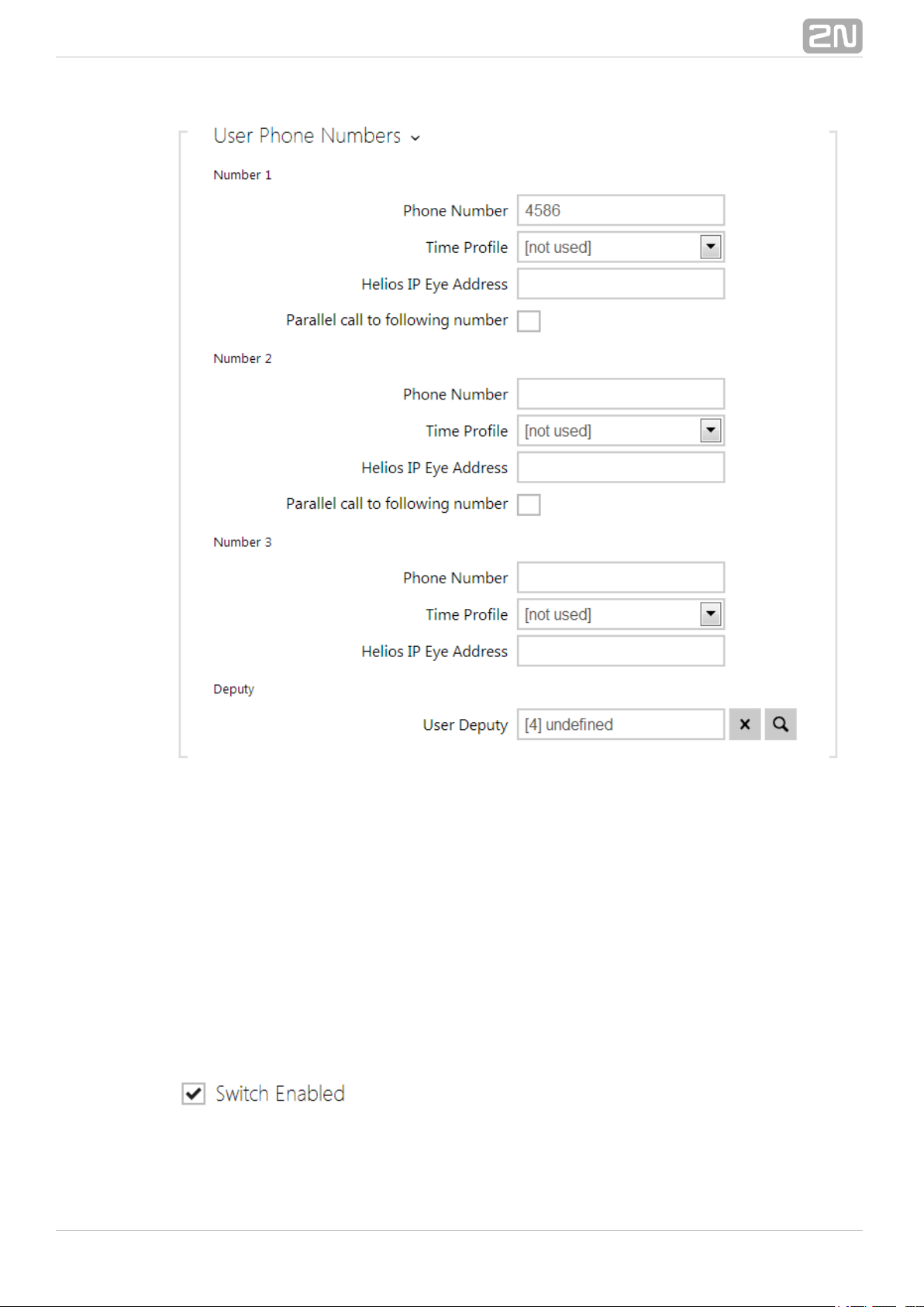
You can assign up to three user phone numbers to each Phone Book position. In case
the user is inaccessible on one number, the following number will be dialled after a
ringing timeout. Enable the to enable diallingParallel call to following number
multiple numbers simultaneously. The phone number validity can also be time
profile-limited.
Phone number – enter the phone number of the station to which the call shall
be routed. Enter the address sip:[user_id@]domain[:port] for Direct SIP calling,
e.g.: sip:200@192.168.22.15 or .sip:name@yourcompany
Enter device:device_name for calls to the application. Set2N Helios IP Mobile
®
the device name in the mobile application. Enter or behind the phone/1 /2
number to specify which SIP account shall be used for outgoing calls (account 1
or 2).
Time profile – assign a time profile to each phone number to define the number
validity. If the profile in inactive, the phone number is not used and the following
phone number is dialled if defined.
Helios IP Eye address – set the address of the PC to be sent a special UDP
message on each active user phone number call. With the aid of this message,
the application displays the camera image screen for those2N Helios Eye
®
users who are not provided with a display-equipped videophone. Enter the
®
242N TELEKOMUNIKACE a.s., www.2n.cz
Page 25
address as follows: ip_address[: ][: ]. The and port1 port2 port1 port2
parameters are optional and are used in case there is Network Address
Translation (NAT) between the PC and intercom and the addresses have to
comply with the router or another NAT-executing device. The port1 (default
value: 8003) parameter defines the destination port for the UDP messages sent
to . The port2 (default value: 80) parameter defines the2N Helios IP Eye
®
destination port for the – intercom HTTP communication.2N Helios IP Eye
®
Parallel call to following number – enable group calling, i.e. calling to more
phone numbers at the same time. You can call the first two numbers, the last
two numbers, or all of the three user numbers in parallel. Answering one call
automatically terminates the other calls.
User deputy – select a user to which the user calls will be routed in the event of
inaccessibility. Enter Phone Book position number or use search button. The
deputy setting is applied when the user fails to answer the call to any of its
phone numbers within the predefined timeout, or if the user numbers are
inaccessible for other reasons (time profiles, user deactivation).
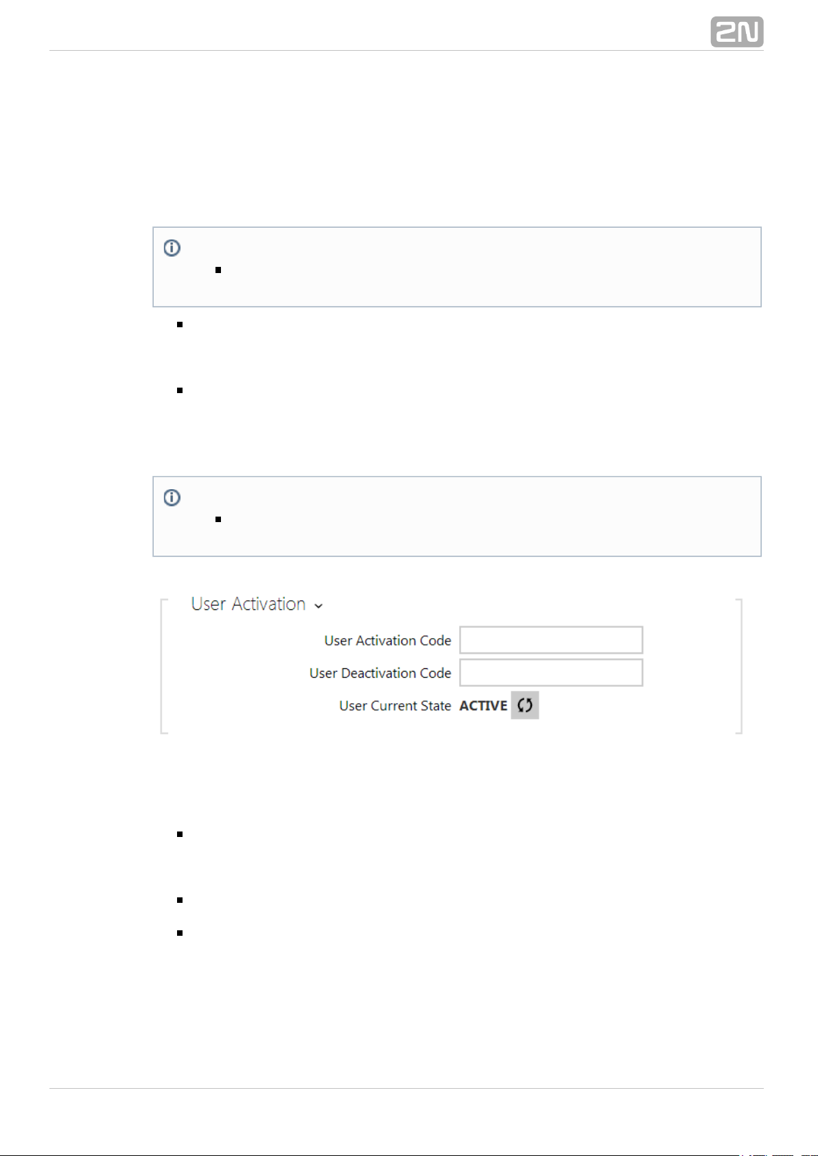
Each intercom user can be assigned its activation/deactivation code for call routing
purposes. If a user is deactivated, calls are routed not to its phone numbers but to the
predefined user deputy at inaccessibility.
User activation code – set a private user activation code: up to 16 characters
including digits 0-9 only. If the user activation code is the only code defined or
the activation and deactivation codes are identical, the activation code is used
both for user activation and deactivation.
User deactivation code – set a private user deactivation code: up to 16
characters including digits 0-9 only.
User current state – select the current state of the user.
Note
The 'Helios IP Eye Address' function is available in selected 2N Helios
®
models only (refer to the model and licence overview).IP
Note
The User Deputy function is available in selected 2N Helios IP®models
).only (refer to the model and licence overview
®
252N TELEKOMUNIKACE a.s., www.2n.cz
Page 26
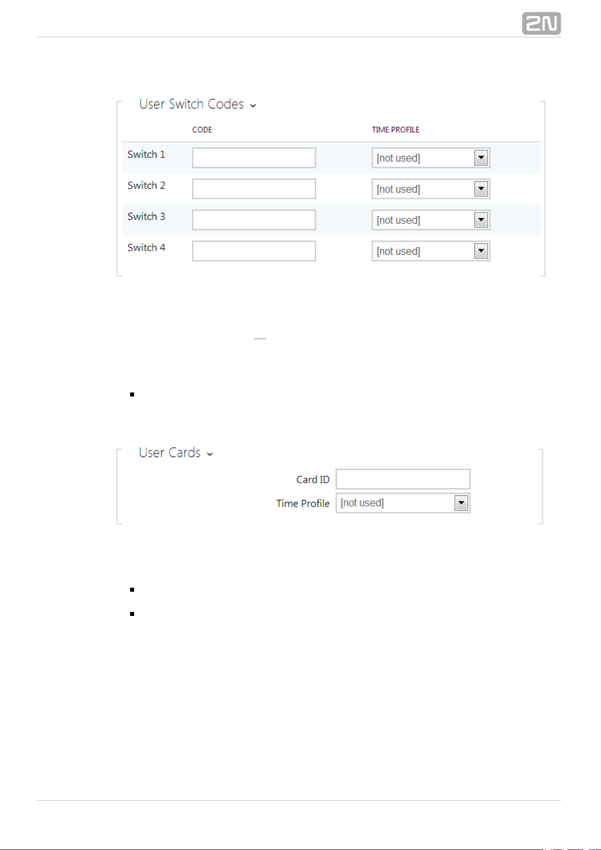
Each user can be assigned a private switch activation code. The user switch codes can
be arbitrarily combined with the universal switch codes defined in the Hardware |
menu. If the codes are identical with the codes already defined in theSwitches
intercom configuration, the mark will appear at the colliding codes.
Code – set a private user switch activation code: up to 16 characters including digits
0–9 only.
Time profile – assign a time profile to the switch code to define the code
validity. If the time profile is inactive, the switch will not be activated by the
code.
Each of the intercom users can be assigned one access RFID card. Refer to the Access
subsection for details.Cards
Card ID – set the user access card ID: 6–16 characters including 0–9, A–F. Each
user can be assigned just one access card.
Time profile – assign a time profile to the user access card to define the card
validity. If the time profile is inactive, the user access card will be detected as
invalid.
®
262N TELEKOMUNIKACE a.s., www.2n.cz
Page 27
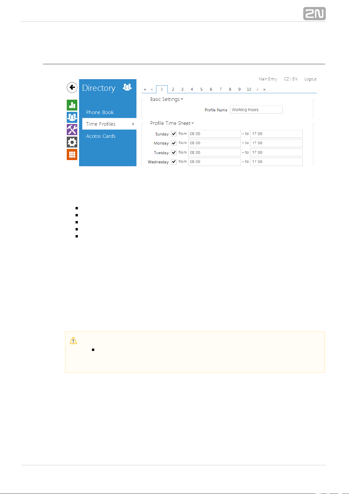
5.2.2 Time Profiles
Such intercom functions as outgoing calls and RFID card/numeric code access, for
example, can be time-limited by being assigned a . By assigning a timetime profile
profile you can:
block all calls to a selected user beyond the set time interval
block calls to selected phone numbers beyond the set time interval
block RFID access for a user beyond the set time interval
block numeric code access for a user beyond the set time interval
block switch activation beyond the set time interval
Assign a time profile according to a week time sheet to define availability of the
selected function. Just set from-to or days in the week on which the function shall be
available. helps you create up to 20 time profiles (depending on the 2N Helios IP
®
2N
model) that can be assigned to the function; refer to the Phone Book, Helios IP
®
Access Cards and Switches settings.
The time profiles are defined not only using the week time sheet but also manually with
the aid of special activation/deactivation codes that you can assign to them after
arriving in/before leaving your office, for example. Enter the activation/deactivation
codes using the numeric keypad of your intercom or phone (during the intercom call).
Refer to the / menu for the time profile settings.Directory Time Profiles
Caution
In case you use the 2N
®
Manager for intercom configuration,Helios IP
we do not recommend you to modify the time profile settings via the web
interface.
®
272N TELEKOMUNIKACE a.s., www.2n.cz
Page 28
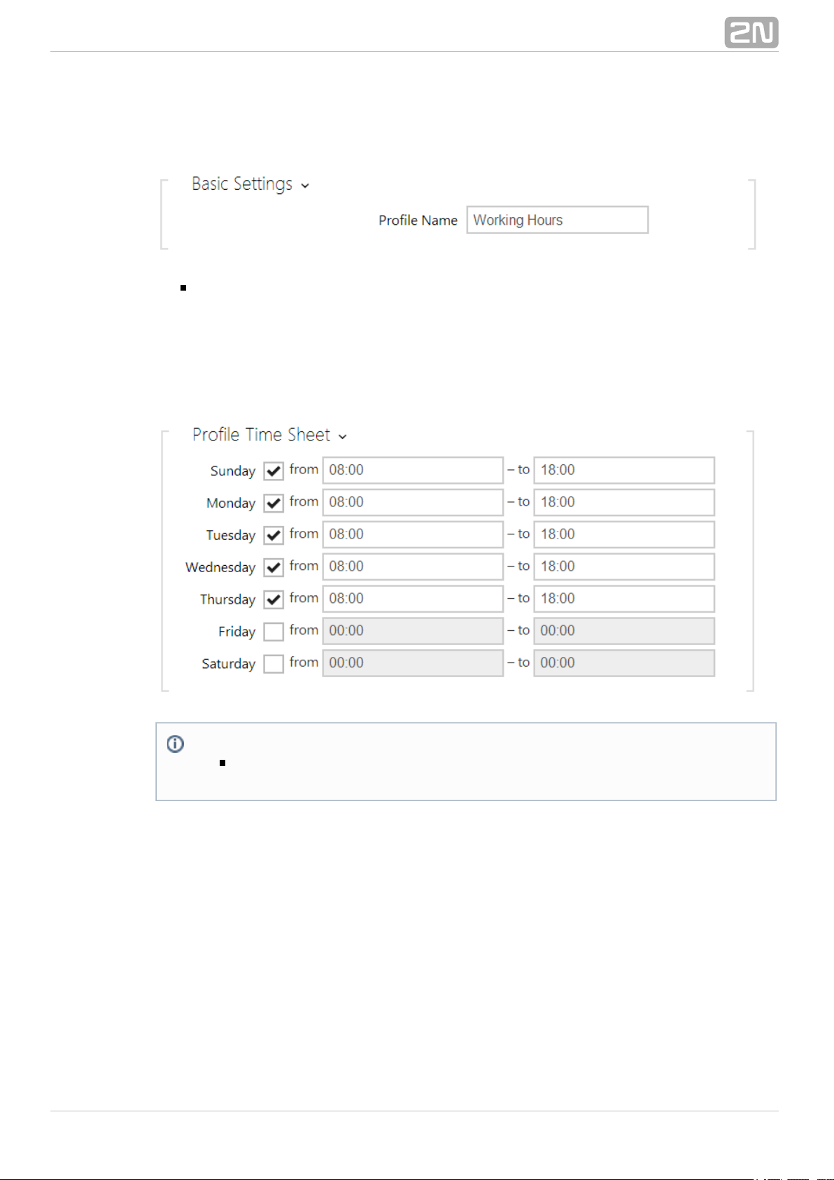
List of Parameters
Profile name – enter a profile name. This parameter is optional and helps you
find items in the time profile list and select profiles in the switch, card and phone
number settings more easily.
This parameter helps you set time profiles within a week period. A profile is active
when it matches the set intervals. Make sure that the real time settings are correct
(refer to the Date and Time subsection) to make this function work properly.
If the profile activation/deactivation code is not defined, the profile state is based on
the time sheet exclusively.
If you apply a time profile together with the activation/deactivation code, the profile
will be active only if the time condition is met and the profile is code-activated at the
same time.
Note
Check off a day and set the From/To fields to 00:00 to make a time profile
active the whole day.
®
282N TELEKOMUNIKACE a.s., www.2n.cz
Page 29
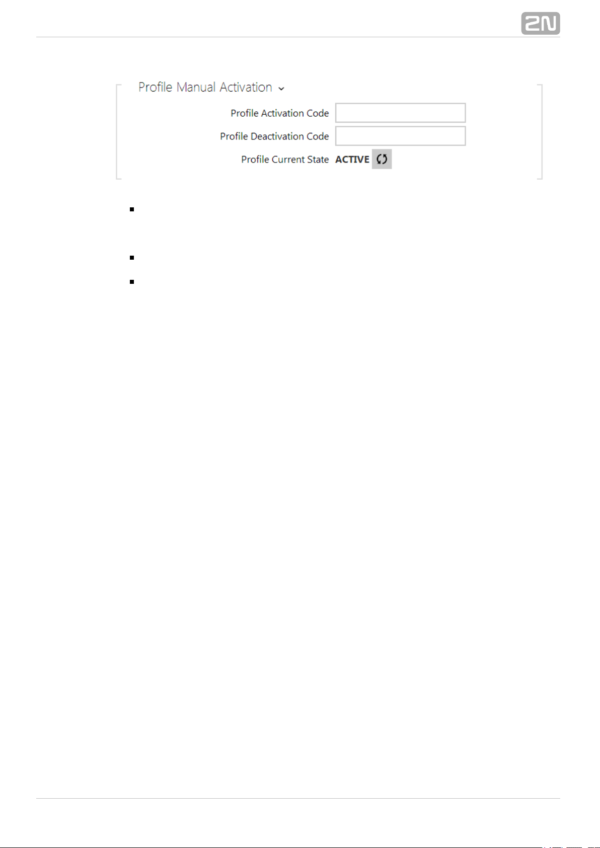
Profile activation code – set the profile activation code: 16 characters
including digits 0–9 only. If the activation code is the only code defined or the
activation and deactivation codes are identical, then the activation code is used
both for profile activation and deactivation.
Profile deactivation code – set the profile deactivation code: 16 characters
including digits 0–9 only.
Profile current state – select the current state of the user.
®
292N TELEKOMUNIKACE a.s., www.2n.cz
Page 30
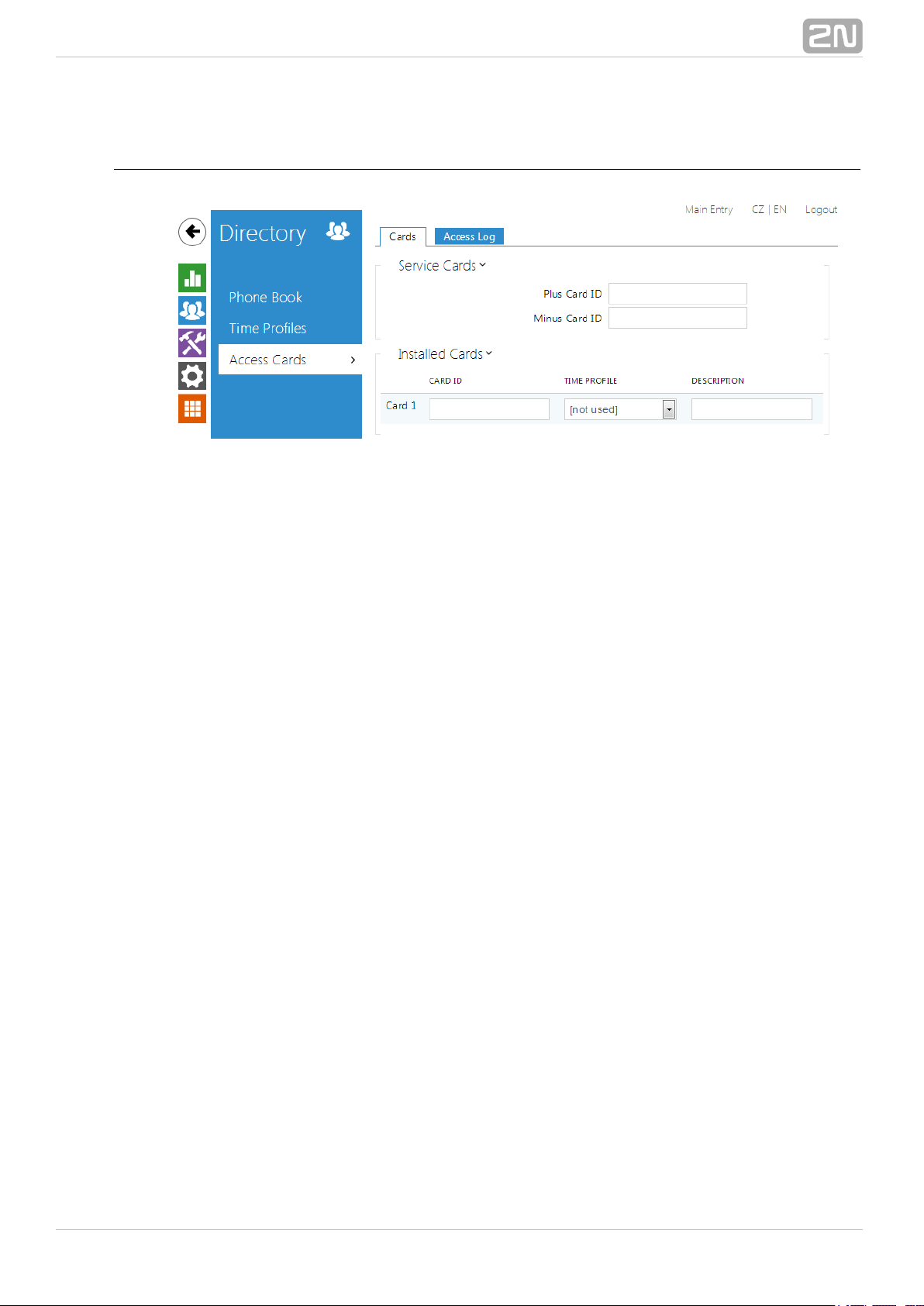
5.2.3 Access Cards
Each intercom user can be assigned one or more access RFID cards. Typically, the card
ID is included in the Phone Book together with such user data as phone numbers,
E-mail address and so on. Or, you can define the RFID cards in the Installed Cards list,
which defines a limited number of unassigned cards reserved for visitors, for example.
You can manage – add, remove and modify items – the list of installed cards manually
via the intercom configuration interface. The main advantage of this list is the option to
add/remove using the Service plus/minus cards without accessing the configuration
interface. Unlike the Phone Book with its up to 1999 positions, the Installed Cards may
contain only 20 cards.
To add a card to the list, apply the plus card and then tap the card to be added on the
reader. The RFID card will be added if the list in not full and does not include the card
yet. To remove a card from the list, apply the minus card and then tap the card to be
removed on the reader. The RFID card record will be cancelled and access via this card
will be blocked.
Service cards help you add/remove cards to/from the list. Enter their IDs in the Plus
Card ID and Minus Card ID fields in the : 6–16 characters including 0–9,Service Cards
A–F (i.e. hexadecimal number of the length of 24 to 64 bits). The number of characters
in the card ID can be different in different card types. However, it holds true that cards
of one and the same type have identically long IDs.
If your external card reader is connected to the intercom via the Wiegand interface, the
card ID is shortened to 6 or 8 characters for transmission (depending on the
transmission parameters). If you apply a card to the reader, you will receive a
complete ID, which is typically longer (8 chars or more). The last 6 or 8 characters,
however, are identical. This is useful for comparing card IDs with the intercom
database: if the IDs to be compared have different lengths, they are compared from
the end and match has to be found in 6 characters at least. If they have identical
lengths, all the characters are compared. This ensures mutual compatibility of the
internal and external readers. Go to the menuDirectory / Access Cards Records/
to identify whether the card was tapped on the internal or external reader.
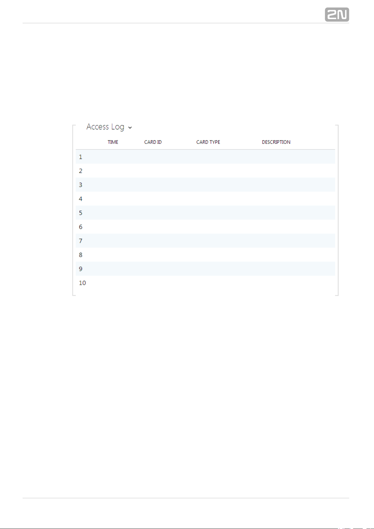
All cards applied via the reader or the Wiegand interface are recorded. Refer to the
menu for the last 10 cards including the cardDirectory Access Cards Records/ /
ID/type, card tapping time and other information if necessary. With small systems, you
can make a trick to enter card IDs: tap the card on the intercom reader and find it in
®
302N TELEKOMUNIKACE a.s., www.2n.cz
Page 31

the . Double-click to select the card ID and push CTRL+C. Now that you haveRecords
the card ID in your box, you can insert it with CTRL+V in any intercom setting field.
Having been read, the card ID is compared with the intercom card database. If the
card ID matches any of the cards in the database, the appropriate action will be
executed: switch activation (door unlocking, etc.). To change the switch number to be
activated, use the parameter in the mAssociated Switch Hardware Card Reader/
enu ( models) or the parame2N Helios IP Vario, Force, Safety
®
Associated Switch
ter in the menu of the card reader module (Hardware Modules/ 2N Helios IP
®
model).Verso
Refer to the menu for the access card settings.Directory Access Cards /
List of Parameters
Cards
Plus card ID – enter the service card ID for adding cards to the Installed cards:
a sequence of 6–16 characters including 0–9, A–F.
Minus card ID – enter the service card ID for removing cards from the Installed
cards: a sequence of 6–16 characters including 0–9, A–F.
Card ID – enter the access card ID: a sequence of 6–16 characters including
0–9, A–F.
Time profile – assign a time profile to the user access card to define the card
validity. If the time profile is inactive, the user access card will be detected as
invalid.
Description – enter such information as the card owner name and similar. The
description gets displayed in the menu whenever the card is appliedRecords
®
312N TELEKOMUNIKACE a.s., www.2n.cz
Page 32
and helps you find the card list items more easily without affecting the intercom
function.
Records
The tab displays the last 10 records on applied cards. Each record includesRecords
the card tapping time, card ID and type and description details (validity, card owner,
etc.).
®
322N TELEKOMUNIKACE a.s., www.2n.cz
Page 33

5.3 Hardware
Here is what you can find in this section:
5.3.1 Switches
5.3.2 Speaker
5.3.3 Microphone
5.3.4 Camera
5.3.5 Keyboard
5.3.6 Display
5.3.7 Card Reader
5.3.8 Extenders
®
332N TELEKOMUNIKACE a.s., www.2n.cz
Page 34

5.3.1 Switches
Switches provide a very flexible and efficient control of such intercom peripherals as
electric door locks, lighting, additional ringing signalling, and so on. allo2N Helios IP
®
ws you to configure up to 4 (depending on model types) independent all-purpose
switches.
A switch can be activated:
by entering the valid code via the intercom numeric keypad or receiving a DTMF
sequence during a call.
by tapping a valid RFID card on the reader.
with a predefined delay after another switch activation.
by an incoming or outgoing call 1).
by pressing a quick dial button 1).
by receiving the HTTP command from another LAN device 1).
via Automation using the Action.ActivateSwitch action.
Switch activation can be blocked by an appropriately selected time profile if necessary.
If a switch is active, you can:
activate any logical output of the intercom (relay, power output).
activate the output to which the Security Relay module is2N Helios IP
®
connected.
send an HTTP command to another device.
The switch can work in the monostable or bistable mode. The switch is switched off
after a timeout in the monostable mode, and switched on with the first activation and
off with the next activation in the bistable mode.
The switch signals its state:
by a programmable beep or a predefined user sound.
by a LED indicator if available in the intercom model.
by an open-door icon on the display if available in the intercom model.
®
342N TELEKOMUNIKACE a.s., www.2n.cz
Page 35

List of Parameters
Switch enabled – enable/disable the switch globally. When disabled, the switch
cannot be activated by any of the available codes (including user switch codes),
by a call or quick dial button.
Switch mode – set the monostable/bistable mode for the switch. The switch is
switched off after a timeout in the monostable mode, and switched on with the
first activation and off with the next activation in the bistable mode.
Switch-on duration – set the switch-on time for a monostable switch. This
value is not applied in the bistable mode.
Time profile – assign the switch a time profile to enable switch-on. If the time
profile is inactive, the switch cannot be activated by a code, call or quick dial
button.
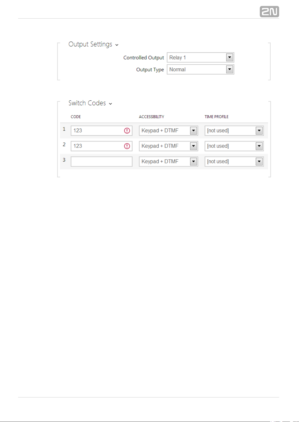
Controlled output – assign an electric output to the switch. Choose one of the
available intercom outputs: relay, power output, extender output. If you select
, the switch will not control any electric output but can control externalNone
equipment via HTTP commands.
Output type – if you use the Security Relay module, set the 2N Helios IP
®
output type to . In the mode, the output works in the inverseSecurity Security
mode, i.e. remains closed and controls the Security Relay module 2N Helios IP
®
using a specific pulse sequence.
Note
Switch time profiles are available with the Gold or Enhanced Integration
licence only.
®
352N TELEKOMUNIKACE a.s., www.2n.cz
Page 36

The table above includes a list of universal codes that help you activate switches from
the phone or intercom keypad. Up to 10 universal codes can be defined for each switch
(depending on the particular intercom model).
Code – enter a numeric code for the switch. The code must include 2 characters
at least but we recommend you to use four characters at least to make the code
accessible from the intercom numeric keypad. Codes 00 and 11 can't be entered
from numeric keypad. Code is confirmed with *.
Accessibility – block the switch activation code entering from the intercom
numeric keypad or your phone.
Time profile – assign a time profile to the switch code to control its validity.
Activation by call – enable switch activation by an incoming or outgoing call,
for example. During an outgoing call the switch is activated after SIP message
180 Ringing is received. The called party confirms ringing by this message. The
switch is active during the whole call in the bistable mode, and activated by the
call beginning and deactivated after the predefined switch-on duration in the
monostable mode.
Note
2N® – be sure to set the internal power supply andHelios IP Vario
switching relay on the configuration connector.
2N® – the security relay is connected to the DOOR +Helios IP Force
and - terminals.
Note
The extended switch activation is available with the Gold or Enhanced
Integration licence only.
®
362N TELEKOMUNIKACE a.s., www.2n.cz
Page 37

Activation by quick dial button – assign a quick dial button to the switch. The
switch is activated whenever the button is pressed.
Sound signalling – set the sound signalling type for switch activation. Choose
the Short beep, Long beep (during the whole activation) or a User sound (refer to
the User Sounds subsection).
Display info – enable/disable signalling of an activated switch on the display.
Synchronise with – set switch synchronisation to enable automatic switch
activation after another switch activation with a predefined delay. Define the
delay in the parameterSynchronisation delay
Synchronisation delay – set the time interval between synchronised activations
of two switches. The parameter will not be applied if the function isSynchronise
disabled.
Command sent upon activation – set the command to be sent to the external
device (WEB relay, e.g.) upon switch activation. The command is sent via the
HTTP (GET request) and must be as follows: http://ip_address/path. E.g.:
.http://192.168.1.50/relay1=on
Command sent upon deactivation – set the command to be sent to the
external device (WEB relay, e.g.) upon switch deactivation. The command is sent
via the HTTP (GET request) and must be as follows: http://ip_address/path.
Note
The HTTP command sending is available with the Gold or Enhanced
Integration licence only .
®
372N TELEKOMUNIKACE a.s., www.2n.cz
Page 38

E.g.: http://192.168.1.50/relay1=off
Enable switch control by HTTP – enable the HTTP switch control option. Refer
to the Switch Control by HTTP details below.
Legacy switch code – enable the option to activate the first-listed switch
When this box is checked,code from the phone without being confirmed with *.
first code does not require confirmation by *. This setting does not apply to other
switch codes listed and to numeric keypad code activation, those must be always
confirmed by *. The Legacy switch code helps you keep back compatibility with
earlier 2N intercom models.
Switch Control by HTTP
To change the switch state, send the HTTP request (GET request) to the intercom
IP address. Make sure that the function is enabled in the Enable Switch Control by
parameter. The request format is as follows: (use any browser to try):HTTP
http://intercom_address/enu/lockstate.xml.p?lock state= &answer=X Y Z
where is the switch number (1–4) and specifies the type of action: 0 – switch off, 1X Y
– switch on, and 2 – state change.
The response to the HTTP request contains an XML message including the current
states of all switches:
<result>
<lock1state>0</lock1state>
<lock2state>0</lock2state>
<lock3state>0</lock3state>
<lock4state>0</lock4state>
</result>
If the parameter is included in the HTTP request, the response in not in theanswer
XML format, but only contains text .Z
Note
The HTTP switch control function is available with the Gold or Enhanced
Integration licence only .
Note
The switch time profiles are available with the Gold or Enhanced
Integration licence only.
®
382N TELEKOMUNIKACE a.s., www.2n.cz
Page 39
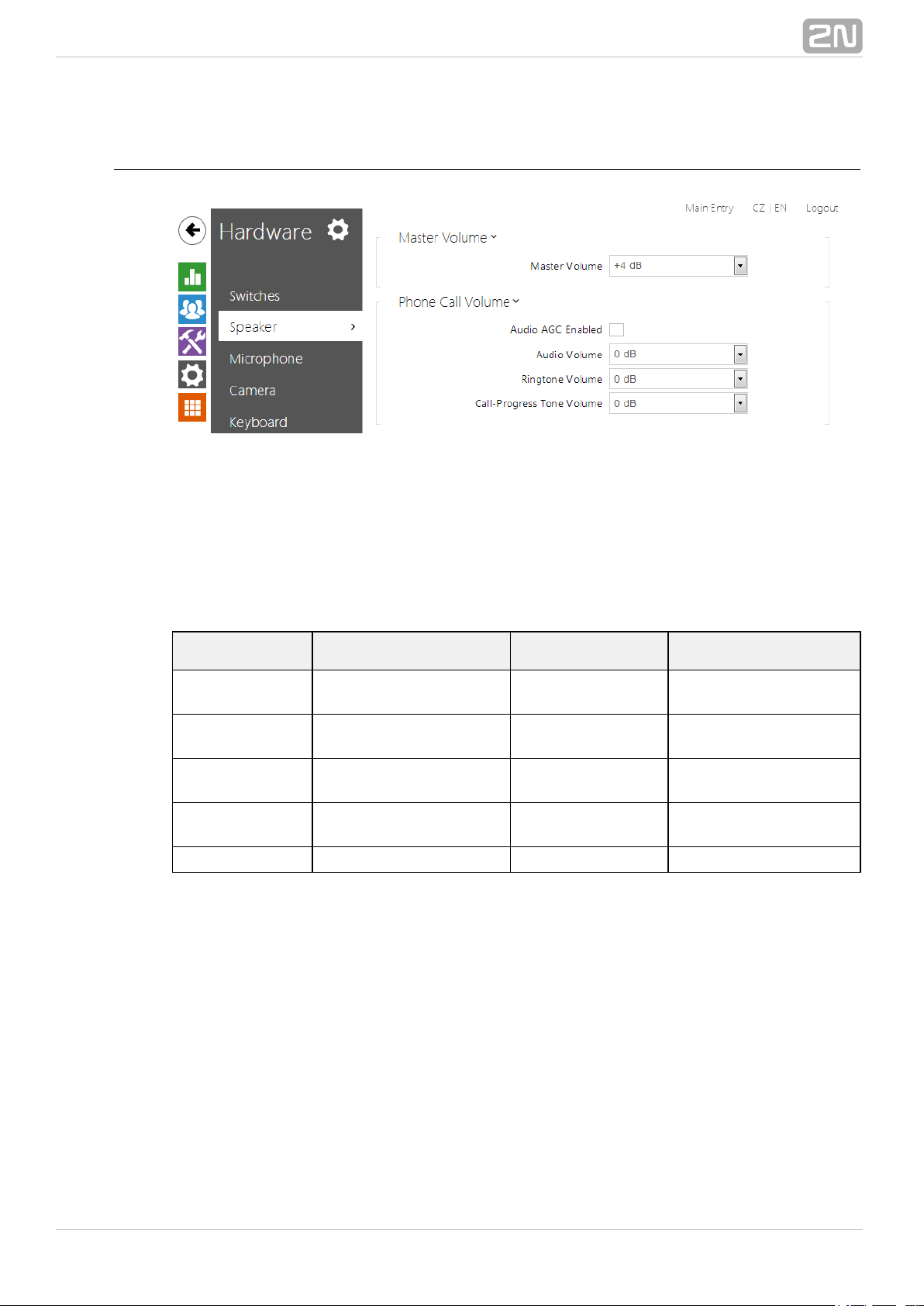
5.3.2 Speaker
All the models are equipped with a speaker or power amplifier output2N Helios IP
®
to which an external loudspeaker can be connected. Set the phone call and state
signalling volume control in this configuration section. The speaker volume settings are
closely associated with the microphone sensitivity parameters as explained below.
Set the intercom speaker volume and microphone sensitivity values in the Master
, and parameters. The valuesvolume Phone call volume Microphone sensitivity
can be different for different intercom models as shown in the table below:
Model Master volume
Phone call
volume
Microphone
sensitivity
Vario
−6 db .. +6 dB (150
mW)
−6 dB .. +18 dB −6 dB .. +6 dB
Force/Safety
1W
−20 dB .. +16 dB (1
W)
−6 dB .. +18 dB −6 dB .. +12 dB
Force/Safety
10W
−20 dB .. +20 dB (10
W)
−6 dB .. +18 dB −6 dB .. +12 dB
Uni
−20 dB .. +16 dB (1
W)
−6 dB .. +18 dB −6 dB .. +12 dB
Verso −12 dB .. 12 dB (2 W) 6 dB .. +18 dB− 6 dB .. +12 dB−
The parameter controls the general loudness of the device, i.e. callMaster volume
and signal volumes, for example. Set the values with respect to the noise level of the
surroundings. People tend to speak more loudly in noise environments than on quiet
places and so remember that the noisier the surrounding environment, the lower the
microphone sensitivity.
The parameter controls the reproduced phone call signal loudness.Phone call volume
Adjust the value if the current master volume is still insufficient for the given
environment. Values higher than +6dB may lead to some signal distortion without
substantially affecting the intelligibility of speech.
The parameter controls the integrated microphone signalMicrophone sensitivity
loudness and affects the audibility of the intercom user. The microphone sensitivity
value is relative against the automatic microphone sensitivity setting in the Master
volume parameter.
®
392N TELEKOMUNIKACE a.s., www.2n.cz
Page 40

List of Parameters
Master volume – set the master volume for the entire system. This setting
affects the volume of phone calls and all signalling tones.
Adaptive volume – enable the adaptive volume mode in which the speaker
volume is adjusted automatically depending on the noise level of the intercom
installation site.
Minimum volume – set the minimum volume in the adaptive mode to avoid
dropping below the acceptable limit.
Maximum volume – set the maximum volume in the adaptive mode to avoid
exceeding of the acceptable limit.
Tip
If the Speaker volume and Microphone sensitivity values exceed + 12 dB
if put together, the sound quality of the intercom-to-phone signal may
deteriorate in some cases due to acoustic feedback between the
microphone and the speaker depending on the intercom installation site
conditions (mounting method, device placement, environment qualities,
surrounding noise, etc.). If you hear interference in your handset during
intercom communication, set the value to LowAEC Artefacts Reduction
or High as necessary.
Note
This setting is available in the adaptive mode supporting models only.
®
402N TELEKOMUNIKACE a.s., www.2n.cz
Page 41
Audio AGC enabled – enable the automatic gain control of the line signal.
Audio volume – set the phone call volume. The volume values are relative
against the set master volume.
Ringtone volume – set the incoming call signal loudness.
Call-progress tone volume – set the dial, ring and busy tone volume. In case
the call-progress tones are automatically generated by the PBX, this setting will
not be applied.
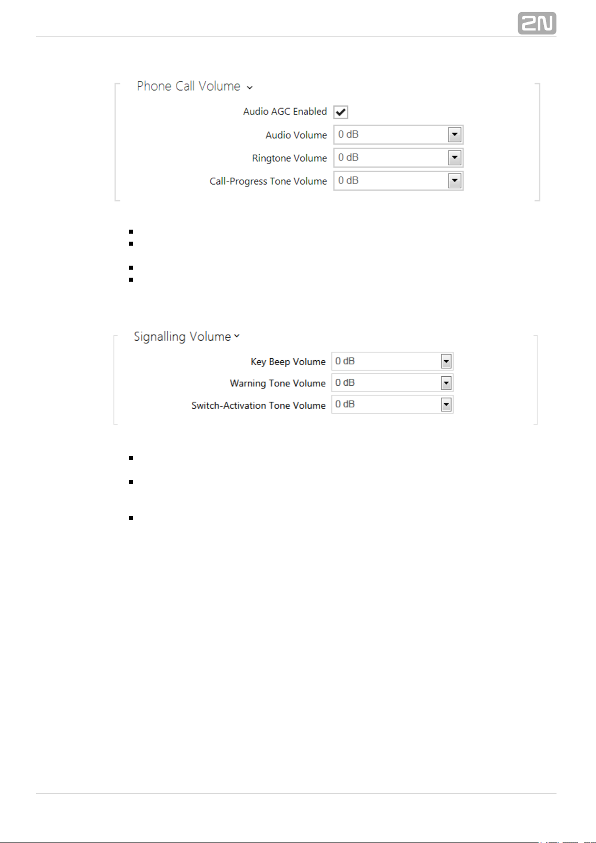
Key beep volume – set the key beep volume. The volume values are relative
against the set master volume.
Warning tone volume – set the volume of warning and signalling tones
described in the section. The volumeSignalling of Operational Statuses
values are relative against the set master volume.
Switch activation tone volume – set the volume of the switch activation tone.
The volume values are relative against the set master volume.
®
412N TELEKOMUNIKACE a.s., www.2n.cz
Page 42

5.3.3 Microphone
Set the microphone and line audio input volume parameters in this intercom
configuration section. The microphone volume settings are closely associated with the
speaker sensitivity parameters and intercom installation site conditions, which affect
the general audio reproduction and recording quality. If you notice a deteriorated audio
quality, please read the subsection carefully too to set the intercom audioSpeaker
parameters on your installation site properly.
List of Parameters
Microphone sensitivity – set the microphone sensitivity.
Microphone AGC enabled – set the automatic gain control (AGC) mode for
the microphone.
AEC artefacts reduction – enable cancelling of interfering noise (i.e. artefacts
caused by cancellation of the local acoustic feedback on the intercom installation
site); refer to the Specification of Audio Parameter Function parameter.
®
422N TELEKOMUNIKACE a.s., www.2n.cz
Page 43

Default audio input – set the default audio input (microphone, line input or
audio module input) for phone calls and audio streaming.
Line input gain – set the line input gain independently of the microphone gain
setting.
Note
This setting is available in the line input supporting models only.
®
432N TELEKOMUNIKACE a.s., www.2n.cz
Page 44

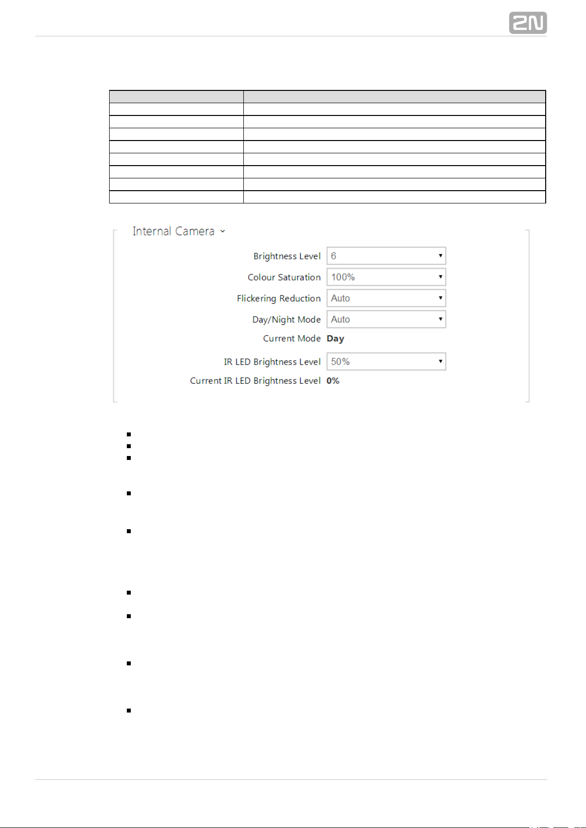
5.3.4 Camera
This menu is only available in the models that are equipped with an2N Helios IP
®
internal camera or can be connected to an external camera. The camera signal can be
streamed directly into the call via a videophone, sent by E-mail, streamed via
ONVIF/RTSP to another device (a video surveillance device, e.g.), or simply HTTP
downloaded from the intercom in the JPEG format.
The following video signal sources can be used:
internal integrated camera or external analogue camera (2N Helios IP Video
®
only)Kit
standard external IP camera supporting MJPEG/RTSP stream with VGA (640 x
480) resolution
The menu helps you set such camera parameters as brightness, colourCamera
saturation and external IP camera login data if necessary. Refer to the Services
and menus for the video/ Phone, Services Streaming / Services E-Mail /
call/streaming parameters.
List of Parameters
Default video source – set the default video signal source. Choose an Internal
camera (or an analogue camera connected to the intercom) or an External IP
camera.
PTZ control enabled – enable the PTZ (Pan-Tilt-Zoom) function to control the camera
display area during the call via DTMF (for 2N® Helios IP Verso only) from your IP
phone numeric keypad. Click the * key to enable/disable the PTZ mode. The meanings
®
442N TELEKOMUNIKACE a.s., www.2n.cz
Page 45
of the IP phone keys in the PTZ mode are as follows:
IP phone key PTZ mode function
* Enable/disable PTZ
1 Zoom in
3 Zoom out
2 Move cropped display up
4 Move cropped display to the left
6 Move cropped display to the right
8 Move cropped display down
5 Return to initial state
Brightness level – set the camera image brightness level.
Colour saturation – set the camera image colour saturation.
Flickering reduction – set reduction of image flickering caused by artificial light
sources (fluorescent lamps, e.g.). Select your network frequency or keep the
setting.Auto
Automatic framerate decreasing – enable automatic frame rate decreasing
under worsened illumination conditions to improve image quality by lowering the
frame rate.
Image trimming – the camera view angle allows you to2N Helios IP Force
®
scan the largest area possible. Use this parameter to enable automatic camera
image trimming to eliminate the (sometimes annoying) view of the intercom
frame. Disable this function to get the maximum possible view angle. The
parameter is available in the models only.2N Helios IP Force
®
Day/Night mode - set the camera day/night mode. The options are automatic
(controlled by the ambient light level), or permanently day or night mode.
Current mode - display the currently selected camera mode (day/night). in the
day mode, the camera uses an IR suppressing filter and infrared illumination is
disabled. In the night mode, the IR suppressing filter is disabled and infrared
illumination is on.
IR LED brightness level - set the infrared LED brightness level in the range
of 0-100% in several steps. Infrared illumination is automatically activated if the
intercom detects lack of ambient light and the camera image is used. The IR LED
brightness level settings are only available in the model. 2N® Helios IP Verso
Current IR LED brightness level - display the current IR LED brightness level
percentage. The level can be decreased below the set value so thatautomatically
the maximum power consumption cannot be exceeded (typically, when multiple
®
452N TELEKOMUNIKACE a.s., www.2n.cz
Page 46
extenders are connected and PoE supply is used).
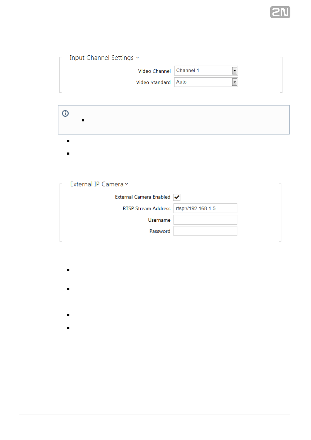
Video input – choose one of the analogue camera inputs. You can change the
input by automation via the Action.SetCameraInput during operation.
Video standard – set the video standard for the camera connected. Modify the
value only if the automatic video standard detection does not work well (Auto
value).
External camera enabled – enable RTSP stream download from the external IP
camera. Complete the valid RTSP stream address or the username and password
to make the function work properly.
RTSP stream address – enter the IP camera RTSP stream address:
rtsp://camera_ip_address/parameters. The parameters are specific for the
selected IP camera model. If you choose another intercom for2N Helios IP
®
the external camera, enter http://ip_address/mjpeg_stream
Username – enter the username for the external IP camera authentication. The
parameter is obligatory only if the external IP camera requires authentication.
Password – enter the external IP camera authentication password. The
parameter is obligatory only if the external IP camera requires authentication.
Note
This setting is only available in the models equipped with an external
analogue camera input.
®
462N TELEKOMUNIKACE a.s., www.2n.cz
Page 47

5.3.5 Keyboard
This configuration section helps you set the numeric keypad and quick dial button
functions. allows you to:2N Helios IP
®
use the numeric keypad for dialling common phone numbers
use the numeric keypad for dialling a Phone Book position
use the numeric keypad for entering the access code for door unlocking, e.g.
set the # function
set the quick dial button functions during a call
set the timeout for entering codes and phone numbers
set the function of the buttons and keys of the connected 2N Helios IP
®
unitsAudio/Video Kit
List of Parameters
Basic Settings
Button function during call – set the quick dial button function during a call.
You can only set the button that initiated the call. The following options are
available:
Note
The 2N® models that are not equipped with a numeric keypad,Helios IP
do not provide all setting options mentioned herein.
®
472N TELEKOMUNIKACE a.s., www.2n.cz
Page 48
None – button pressing does not affect the call setup or active call.
Hang up – button pressing terminates the call setup or active call.
Dial the following – button pressing initiates dialling of the following user
number in the Phone Book. This accelerates the dialling process in case the
user is inaccessible on some of its phone numbers.
Flash – button pressing sends a special DTMF character (FLASH) into the
current call, to which the connected PBX can response with the selected
action.
Restore network settings by buttons – enable restoration of the default
network settings by pressing a sequence of the quick dial buttons after the
intercom restart as described in the subsection in theDevice Configuration
Installation Manual of the respective model.
Enable calling to position number – enable calling to a Phone Book user by
dialling the user position number (2 to 4 digits) and pressing * for confirmation.
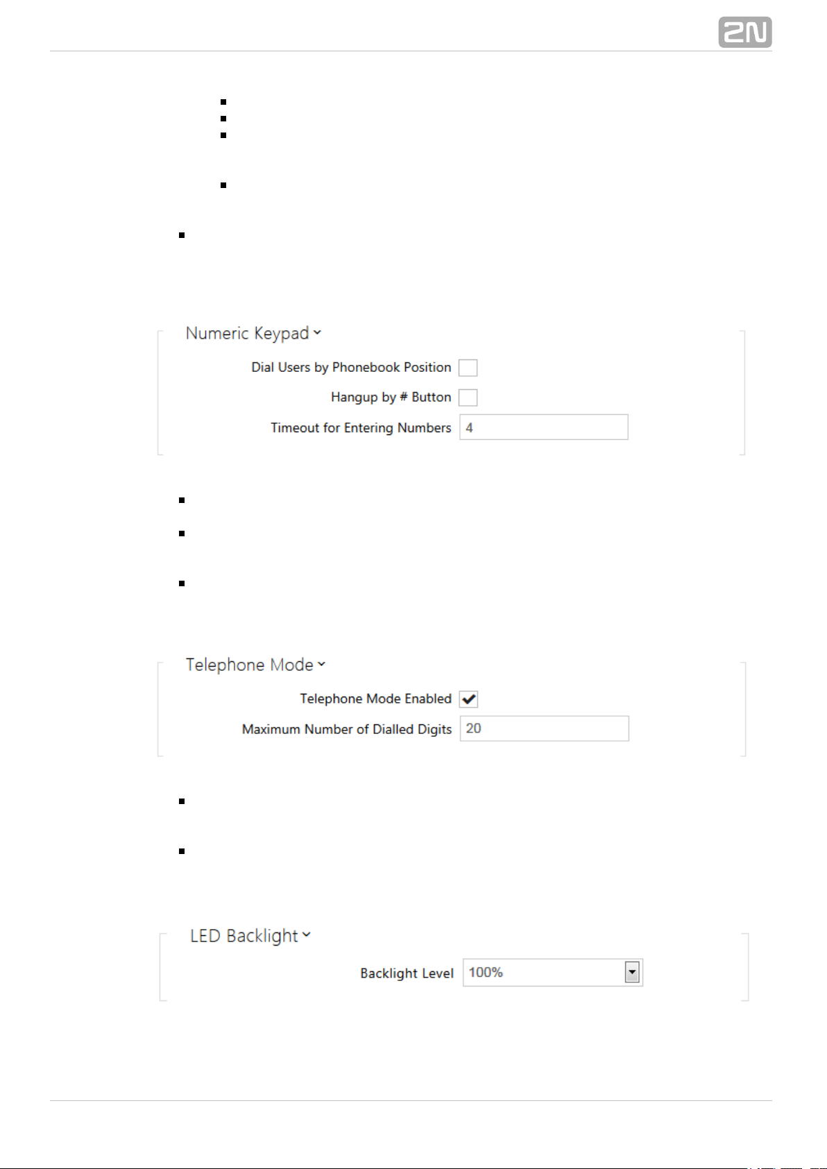
Hang up by # button – enable termination of the active call by the # key. If
the call was initiated by a quick dial button, the same button has to be
repressed; refer to the parameter.Button function during call
Timeout for entering numbers – set the maximum interdigit timeout for code
or phone number dialling via the intercom numeric keypad. When the timeout
elapses, the dialling is automatically confirmed as if the * key was pressed.
Telephone mode enabled – enable the option to set up calls directly to the
phone numbers dialled via the intercom numeric keypad. Enter the
key sequence to set up the call.* telephone_number *
Maximum number of dialled digits – set the maximum count of digits for a
phone number in the Telephone mode. When this limit is reached, the number is
dialled automatically without pressing *.
®
482N TELEKOMUNIKACE a.s., www.2n.cz
Page 49

Backlight level – set the keypad and button backlight level.
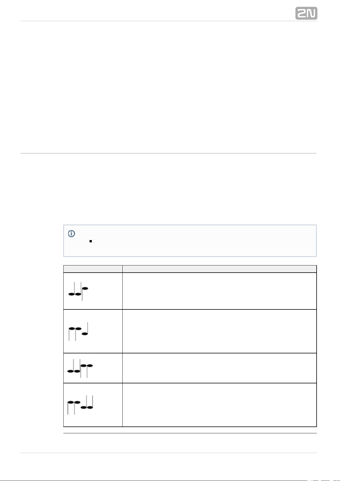
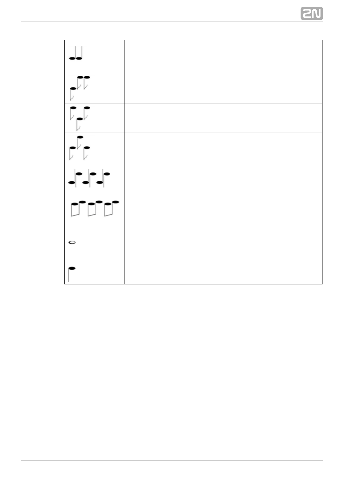
Keyboard Mapping
The and models are equipped2N Helios IP Audio Kit
®
2N Helios IP Video Kit
®
with eight terminals for up to 16 external buttons or a keypad. The functions can be set
for each button separately.
The buttons and their settings are arranged in a matrix of 4 columns x 4 rows; see the
figure below.
The figure below shows the default button settings.
You can assign one function to each matrix position: numeric keypad keys 0 through 9,
*, # or one of the quick dial buttons 1–16.
®
492N TELEKOMUNIKACE a.s., www.2n.cz
Page 50

5.3.6 Display
Some models are equipped with a colour display. Configure the2N Helios IP Vario
®
display exclusively via the . In this menu, you can only switch2N Helios IP Manager
®
the display on/off and set a few parameters.
List of Parameters
Display enabled – enable/disable the display function.
Ad screen activation timeout – set the maximum idle time (i.e. time during
which the user does not control the device using the buttons or numeric keypad)
after which the advertisement displaying mode is switched on automatically.
Quick dial screen activation timeout – set the maximum idle time (i.e. time
during which the user does not control the device using the buttons or numeric
keypad) after which the Phone Book is switched into the nametag displaying
mode.
Phone Book search mode – set the Phone Book searching mode. You can
search users either according to the first username characters (Prefix only) or an
arbitrary incidence of the selected characters in the username (Arbitrary
®
502N TELEKOMUNIKACE a.s., www.2n.cz
Page 51

incidence).
®
512N TELEKOMUNIKACE a.s., www.2n.cz
Page 52

5.3.7 Card Reader
This menu is available in the and models2N Helios IP Vario
®
2N Helios IP Force
®
only. Configure the card reader in the menu.2N Helios IP Verso
®
Extenders
The card reader helps you control access to your building effectively using contactless
RFID cards. The supported card types depend on the card reader model used.
The and card readers are equipped with2N Helios IP Vario
®
2N Helios IP Force
®
an input/output Wiegand interface. The interface direction is configurable. In the input
mode, the interface can be used for connection of external card readers, fingerprint
readers, biometric data readers and so on. In the output mode, the interface helps
connect the intercom to the security exchange, e.g. and send IDs of the cards tapped
on the internal reader to this exchange.
The (91371…U) and all models are2N Helios IP Vario
®
2N Helios IP Force
®
equipped with a red LED indicator. You can control the LED state via the digital inputs
on the card reader. Typically, this function helps signal the secured/unsecured state via
a wire from the security exchange to the intercom connected to one of the card reader
inputs.
List of Parameters
®
522N TELEKOMUNIKACE a.s., www.2n.cz
Page 53

Card reader enabled – enable the card reader function. If disabled, the card
reader ignores all applied cards. If the card is disabled and the Wiegand interface
is OUT, all codes of the used cards are resent to the Wiegand interface.
Associated switch – select a switch to be activated whenever a valid card is
applied.
Accepted HID cards – set the type of HID Prox cards to be accepted by the card
reader. The card reader supports just one card type at an instant. This setting is not
applied if you do not use the HID Prox cards.
Interface mode – enable the Wiegand function and set Wiegand IN/OUT. The
IDs of the cards tapped on the internal card reader are always resent to Wiegand
OUT.
Message format – set the sent/received message format: 26-bit, 32-bit, 37-bit
or RAW.
Change facility code – set the mode in which the first 8 bits of the 24 card ID
resent to the Wiegand interface are replaced with the value included in the
. The parameter is applied only if the Wiegand is OUT.Facility code
Facility code – enter the facility code for card ID resending to Wiegand.
Red LED control – enable the red LED control according to the card reader
digital input states. The values defines the condition under which the red LED
shall be on.
®
532N TELEKOMUNIKACE a.s., www.2n.cz
Page 54

5.3.8 Extenders
The intercoms can be enhanced with extending modules2N Helios IP Verso
®
connected to the intercom basic unit. The following modules are available:
five-button module
keypad module
Infopanel module
card reader module
I/O module
Wiegand module
The modules are chain-like interconnected. Each of the modules has its number
depending on the chain position (the first module has number 1). The basic unit is a
special type of module and has number 0.
You can configure each module separately. The parameters are specific for the given
module type.
Brightness
This tab helps you control the backlight level of nametags, buttons and brightness of
signalling LEDs. You can set backlight brightness for the day and night. The intercom
automatically chooses the appropriate backlight level from a predefined range of values
according to the ambient light intensity.
If the Brightness during day and Brightness during night are set to one and the same
value, the ambient light level is ignored.
Note
The modules can also be configured via the text line with a list of
parameters (parameter_name=parameter_value) separated with
semicolons. At present, just a few of these parameters are available. The
other parameters are not public as they are rather experimental and can
be modified in the future.
®
542N TELEKOMUNIKACE a.s., www.2n.cz
Page 55

Brightness during day - set the LED brightness percentage value for the day
mode.
Brightness during night - set the LED brightness percentage value for the
night mode.
Current brightness - display the current LED brightness value automatically
selected according to the ambient daylight level.
Poznámka
The brightness parameters affect the function, power consumption and
general appearance of your device. A high nametag and button backlight
value may, if the ambient light level is low, dazzle the persons standing in
front of the intercom and, in general, increase the power consumption of
the device. A low LED brightness value, on the other hand, may, if the
intercom is placed in direct sun, result in a lower LED on/off contrast and
potential LED state identification problems.
®
552N TELEKOMUNIKACE a.s., www.2n.cz
Page 56

Basic Unit Module Configuration
Output 1 maximum power - set the maximum load to be connected to the
power output available on the basic unit. When he the output is active, t
consumption of the other modules (backlight level, etc.) can be adjusted
automatically in order that the maximum allowed consumption of the intercom
cannot be exceeded.
Button Module Configuration
Button function – assign Phone Book positions to the buttons.
®
562N TELEKOMUNIKACE a.s., www.2n.cz
Page 57

Keypad Module Configuration
No parameters are available to the public at present.
Infopanel Module Configuration
No parameters are available to the public at present.
®
572N TELEKOMUNIKACE a.s., www.2n.cz
Page 58

Card Reader Module Configuration
Associated switch – set the number of the switch to be activated by tapping of
a valid RFID card.
Forward to Wiegand output - set a group of Wiegand outputs to which all the
received RFID card IDs will be resent.
I/O Module Configuration
Module name – set the module name for input/output specification in the
SetOutput, GetInput and InputChanged objects in . 2N Helios IP Automation
®
®
582N TELEKOMUNIKACE a.s., www.2n.cz
Page 59

Wiegand Module Configuration
The Wiegand module is equipped with the input and output , whichWiegand interfaces
are mutually independent, have separate settings and can receive and send codes at
the same time. The Wiegand input helps you connect such equipment as RFID card
readers, biometric readers and so on. With the Wiegand output, you can connect the
intercom to the security system in your building, for example (to send IDs of the RFID
cards tapped on the RFID reader or codes received on any Wiegand input). The
Wiegand module is also equipped with one logical input and one logical output, which
can be controlled via 2N Helios IP Automation®.
Module name - set the module name for input/output specification in
the SetOutput, GetInput and InputChanged objects in the 2N Helios
®
settings. IP Automation
Associated switch - set the number of the switch to be activated whenever a
valid code is received.
Received code format - set the format for the codes to be received (Wiegand
26, 32, 37 and RAW).
Forward to Wiegand output - set the group of Wiegand outputs to which all
the received codes will be resent.
Transmitted code format - set the format for the codes to be
transmitted (Wiegand 26, 32, 37 and RAW).
Output Wiegand group - assign the output Wiegand group to which the codes
from the connected card readers or Wiegand inputs can be resent.
®
592N TELEKOMUNIKACE a.s., www.2n.cz
Page 60

5.4 Services
Here is what you can find in this section:
5.4.1 Phone
5.4.2 Streaming
5.4.3 ONVIF
5.4.4 E-Mail
5.4.5 Automation
5.4.6 User Sounds
5.4.7 Web Server
5.4.8 Audio Test
®
602N TELEKOMUNIKACE a.s., www.2n.cz
Page 61

5.4.1 Phone
The Phone service is one of the basic functions of the intercom: helps you establish
connections with other IP network terminal equipment. The intercoms2N Helios
®
support the extended SIP and are compatible with and certified by the leading SIP PBX
and terminal equipment manufacturers (CISCO, Avaya, Broadsoft, etc.).
The intercom supports up to five parallel calls: 1 outgoing and up to 4 incoming calls.
Just one of the calls can be – the audio stream is interconnected with theactive
microphone and speaker and video stream with the camera. The other calls are always
– the microphone and speaker are muted, the intercom receives the DTMFinactive
characters for the opponent to control the intercom (activate/deactivate profiles, users,
etc.).
Typically, the intercoms are used for outgoing calls and incoming calls are inactive –
the microphone and speaker are muted. However, you can configure your intercom to
make incoming calls active and ringing; refer to the tab. Press the * and # keysCalls
on the numeric keypad to answer and terminate an incoming call.
The intercoms use the , and protocols (with a licence2N Helios IP
®
G.711 L16 G.729
key) to encrypt or compress audio streams and the or codecs toH.263 H.264
compress video streams. Choose your preferential codecs in the or tab.Audio Video
®
612N TELEKOMUNIKACE a.s., www.2n.cz
Page 62

Explanation of IP Telephony Terms
SIP – is a phone call signalling transmission(Session Initiation Protocol)
protocol used in IP telephony. It is primarily used for setting up, terminating and
forwarding calls between two SIP devices (the intercom and another IP phone in
this case). SIP devices can establish connections directly with each other (Direct
SIP Call) or, typically, via one or more servers: SIP Proxy and SIP Registrar.
SIP Proxy – is an IP network server responsible for call routing (call transfer to
another entity closer to the destination). There can be one or more SIP Proxy
units between the users.
SIP Registrar – is an IP network server responsible for user registration in a
certain network section. As a rule, SIP device registration is necessary for a user
to be accessible to the others on a certain phone number. SIP Registrar and SIP
Proxy are often installed on one and the same server.
RTP – is a protocol defining the standard(Real-Time Transport Protocol)
packet format for audio and video transmission in IP networks. 2N Helios IP
®
uses the RTP for audio and video stream transmission during a call. The stream
parameters (port numbers, protocols and codecs) are defined and negotiated via
the SDP (Session Description Protocol).
The intercoms support three ways of SIP signalling:2N Helios IP
®
via the ( ), which is the most frequently usedUser Datagram Protocol UDP
unsecured signalling method
via the , which is less frequent, yetTransmission Control Protocol ( TCP)
recommended unsecured signalling method
via the protocol, where SIP messages areTransaction Layer Security (TLS)
secured against third party monitoring and modification
List of Parameters
The Phone settings are arranged in five tabs:2N Helios IP
®
SIP 1 and SIP 2 – complete SIP terminal settings
Calls – incoming and outgoing call settings
Audio – audio codec, DTMF transmission and other audio stream transmission
settings
Video – video codec, video resolution and other video stream transmission
settings
®
622N TELEKOMUNIKACE a.s., www.2n.cz
Page 63

SIP 1 and SIP 2
The 2N® Helios IP intercoms allow two independent SIP accounts (SIP 1 and SIP 2 tabs)
to be configured. Thus, the intercom can be registered under two phone numbers, with
two different SIP exchanges and so on. Both the SIP accounts process incoming calls
equivalently. Outgoing calls are primarily processed by account 1, or, if account 1 is not
registered (due to SIP exchange error, e.g.), by account 2. Select the account number
for the phone numbers included in the phone directory to specify the account to be
used for outgoing calls (example: 2568/1 - calls to number 2568 go via account 1, sip:
calls to s1234@192.168.1.1. ip uri via account 2).
Display name – set the name to be displayed as CLIP on the called party's
phone.
Phone number (ID) – set the intercom phone number (or another unique ID
including characters and digits). Together with the domain, this number
represents a unique intercom identification in calls and registration.
Domain – set the domain name of the service with which the intercom is
registered. Typically, it is identical with the SIP Proxy or Registrar address.
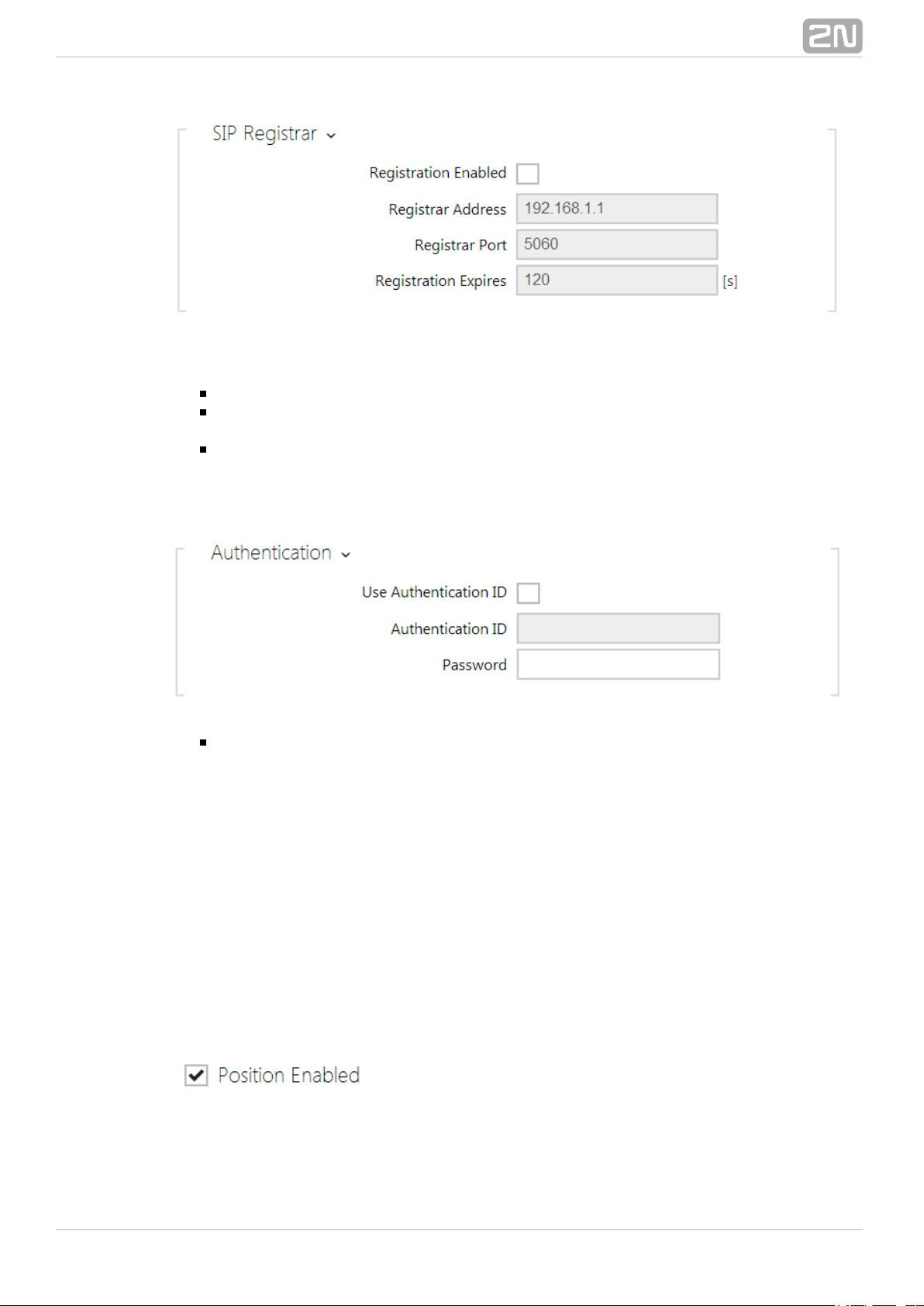
Use authentication ID – enable the use of an alternative ID for intercom
authentication. If disabled, the phone number defined above is used for
authentication.
Authentication ID – enter the alternative ID for authentication.
Password – enter the password for authentication. The parameter is applied on
if your PBX requires authentication.
®
632N TELEKOMUNIKACE a.s., www.2n.cz
Page 64

Proxy address – set the SIP Proxy IP address or domain name.
Proxy port – set the SIP Proxy port (typically 5060).
Registration enabled – enable intercom registration with the set SIP Registrar.
Registrar address – set the SIP Registrar IP address or domain name.
Registrar port – set the SIP Registrar port (typically 5060).
Registration expires – define the registration expiry, which affects the network
and SIP Registrar load by periodically sent registration requirements. The SIP
Registrar can modify the expiry limit without letting you know.
SIP transport protocol – set the SIP communication protocol: UDP (default),
TCP or TLS.
®
642N TELEKOMUNIKACE a.s., www.2n.cz
Page 65

Trusted certificate – specify one of the three sets of certificates issued by
certification authorities to verify the SIP server public certificate validity, refer to
the Certificates subsection. If none is included, the SIP server public certificate is
not verified.
User certificate – specify the user certificate and private key to verify the
intercom authorisation to communicate with the SIP server. There are three sets
of user certificates and private keys, refer to the Certificates subsection.
Local SIP port – set the local port to be used for SIP signalling. The parameter
is not applied until the intercom is restarted. The default value is 5060.
PRACK enabled - enable the PRACK method for reliable confirmation of SIP
messages with codes 101 - 199.
Send KeepAlive packets – define whether the intercom shall, during a call,
send periodical SIP OPTIONS requests to inquire about the state of the called
station (to detect the station failure, e.g.).
IP address filter enabled – enable the blocking of SIP packet receiving from
addresses other than SIP Proxy and SIP Registrar. The primary purpose of the
function is to enhance communication security and eliminate unauthorised phone
calls.
QoS DSCP value – set the SIP packet priority in the network. The set value is
sent in the TOS (Type of Service) field in the IP packet header.
Starting RTP port – set the starting local RTP port in the range of the length of
60 ports to be used for audio and video transmissions. The default value is 5000
(i.e. the used range is 5060–5059). The parameter is only set for account 1 but
applies to both the SIP accounts.
RTP timeout – set the audio stream RTP packet receiving timeout during a call.
If this limit is exceeded (RTP packets are not delivered), the call is terminated by
the intercom. Set the parameter to 0 to disable this function. The parameter is
only set for account 1 but applies to both the SIP accounts.
Calls
Automatic answer – enable automatic answering of incoming calls. If this
function is disabled, the intercom signals incoming calls by ringing and the user
can answer them by pushing the * button on the numeric keypad.
Call activation – select automatic or manual microphone, speaker or camera
activation during an incoming call. The parameter is applied only if the
is enabled. If you select manual activation, enter theAutomatic Answer
activation code, see below.
Activation code – enter the call activation code via the IP phone numeric
keypad to activate the microphone, speaker and camera if available. The
parameter is applied only if the manual call activation is enabled.
®
652N TELEKOMUNIKACE a.s., www.2n.cz
Page 66

Ring time limit – set the outgoing call setup and ringing time limit after which
the calls shall be automatically terminated. If the calls are routed to the GSM
network via GSM gateways, your are advised to set a value higher than 20 s.
Call time limit – set the call duration limit after which the call is automatically
terminated. The intercom signals termination with a beep 10 s before the call
end. Enter any DTMF character into the call (# on your IP phone, e.g.) to extend
the call time. The limit is valid for both outgoing and incoming calls.
Dial cycles limit – set the maximum count of user deputy dial cycles if the user
dialled by the Phone Book position number is inaccessible. The function helps you
avoid deadlock if the is set to the same value in the Phone Book.User Deputy
Audio
Codec 1–4 – set the order of audio codecs for call setup: G.711 (PCMA or
PCMU), L16 or G.729. The order defines the codec priority, i.e. the first codec has
the highest priority. Codec G.729 is available in selected intercoms only with a
valid licence G.729.
The tab below helps you define how DTMF characters shall be sent from the intercom.
Check the DTMF receiving options and settings of the opponent to make the function
work properly.
®
662N TELEKOMUNIKACE a.s., www.2n.cz
Page 67
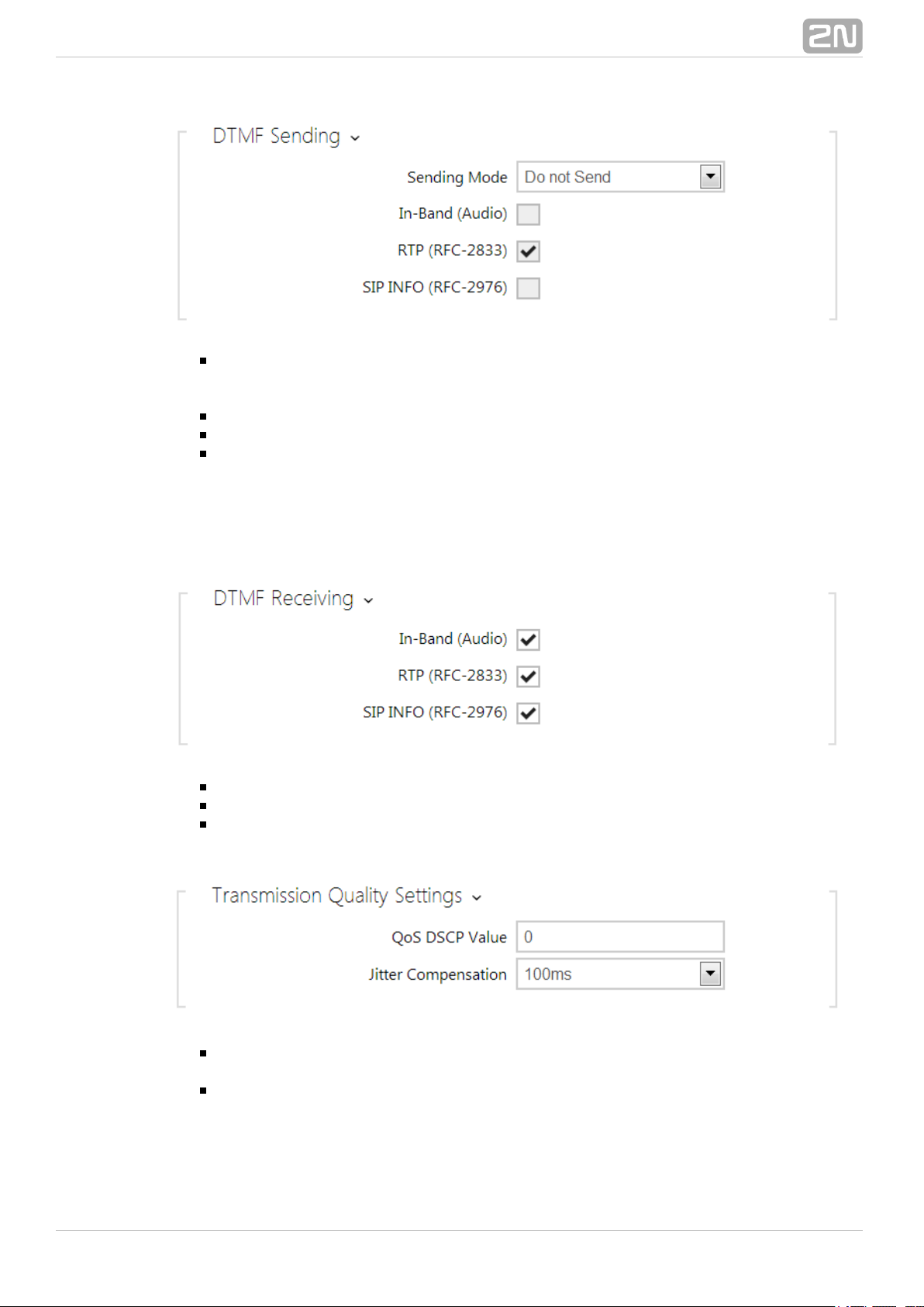
Sending mode – define whether it will be possible to send DTMF during a call by
pressing 0 through 9, * and # on the intercom numeric keypad. Set the sending
mode for incoming/outgoing/all calls.
In-Band (Audio) – enable classic DTMF dual tone sending in the audio band.
RTP (RFC-2833) – enable DTMF sending via the RTP according to RFC-2833.
SIP INFO (RFC-2976) – enable DTMF sending via SIP INFO messages
according to RFC-2976.
The tab below helps you define how DTMF characters shall be received from the
intercom. Check the DTMF receiving options and settings of the opponent to make the
function work properly.
In-Band (Audio) – enable classic DTMF dual tone receiving in the audio band.
RTP (RFC-2833) – enable DTMF receiving via the RTP according to RFC-2833.
SIP INFO (RFC-2976) – enable DTMF receiving via SIP INFO messages
according to RFC-2976.
QoS DSCP value – set the audio RTP packet priority in the network. The set
value is sent in the TOS (Type of Service) field in the IP packet header.
Jitter compensation – set the buffer capacity for jitter compensation in audio
packet transmissions. A higher capacity improves the transmission resistance at
the cost of a greater sound delay.
®
672N TELEKOMUNIKACE a.s., www.2n.cz
Page 68

Video
Codec 1–4 – set the order of video codecs for call setup: H.264, H.263+ or
H.263. The order defines the codec priority, i.e. the first codec has the highest
priority.
Video resolution – set the video resolution for phone calls.
Video framerate – set the video frame rate for phone calls.
Video bitrate – set the video stream bit rate for phone calls.
QoS DSCP value – set the video RTP packet priority in the network. The set
®
682N TELEKOMUNIKACE a.s., www.2n.cz
Page 69

value is sent in the TOS (Type of Service) field in the IP packet header.
Maximum packet size – set the size limit for the video RTP packets to be sent.
H.264 payload type (1) – set the payload type for video codec H.264
(packetisation mode 1). Set a value from the range of 96 through 127, or 0 to
disable this codec type.
H.264 payload type (2) – set the payload type for video codec H.264
(packetisation mode 2). Set a value from the range of 96 through 127, or 0 to
disable this codec type.
H.263+ payload type – set the payload type for video codec H.263+
(packetisation mode 3). Set a value from the range of 96 through 127.
Polycom compatibility mode – set SDP compatibility with some earlier
Polycom and Cisco phone models. If this mode in on, the intercom does not send
the flag in the SDP message in the video codec offer.sendonly
®
692N TELEKOMUNIKACE a.s., www.2n.cz
Page 70

5.4.2 Streaming
The intercoms provide several audio/video streaming methods; refer to 2N Helios IP
®
the table below:
Transmission
method
Description
JPEG/HTTP Static JPEG image transmission. Refer to the JPEG tab below.
MJPEG/HTTP
A series of consecutive JPEG images, the Server Push multipart/x-mixed-replace method. Refer to the JPEG tab below.
RTSP + RTP/UDP
RTSP with separate RTP/UDP audio and video streams. Supported
both for audio (G.711) and video (H.264, H.263, MPEG-2 and
MJPEG). .Refer to the RTSP tab below
RTP/RTSP
RTP tunnelling via RTSP. audio (G.711) andSupported both for
video (H.264, H.263, MPEG-2 and MJPEG). Refer to the RTSP tab
.below
RTP/RTSP/HTTP
RTSP tunnelling via HTTP. audio (G.711) andSupported both for
video (H.264, H.263, MPEG-2 and MJPEG). Refer to the RTSP tab
.below
RTP/UDP-Multicast
Uncontrolled RTP packet multicast. Supported for audio (G.711)
only. .Refer to the Multicast tab below
®
702N TELEKOMUNIKACE a.s., www.2n.cz
Page 71

Explanation of Terms
RTP (Real-Time Transport Protocol) – is a protocol defining the standard packet
format for audio/video transmission via IP networks. employs 2N Helios IP
®
this protocol for audio/video streaming. The RTP transport protocol is either UDP
or also RTSP and HTTP.
RTSP – is a network protocol for streaming(Real-Time Streaming Protocol)
server control (controls setting up, launching and stopping of audio/video
streams).
HTTP – helps transmit practically any contents(Hypertext Transfer Protocol)
and is used primarily by internet browsers for web server communication. 2N
®
uses the HTTP to transmit static JPEG images or MJPEG streams viaHelios IP
the HTTP Server Push.
IP Multicast – is a way of parallel sending of IP packets from one source to
multiple stations via IP networks. uses IP multicast for sending2N Helios IP
®
and receiving audio streams.
ONVIF (Open Network Video Interface Forum) – is a set of video camera
search, configuration and administration specifications for the IP network. The
intercoms are ONVIF compatible and fully implement the ONVIF2N Helios IP
®
Profile S.
JPEG – is a standard method of lossy compression of images.
MJPEG – is a video stream encoding format in which each image is compressed
separately by JPEG. MJPEG encoding produces high-quality video at a
significantly higher bit rate compared to the methods mentioned below.
H.263 – is a video stream compression standard used in telecommunications.
Unlike MJPEG, H.263 uses differences between consecutive images and provides
a significantly higher level of compression to the detriment of the video stream
quality.
H.263+ – is like H.263, but supports a different bit stream packetisation
method.
MPEG-4 part 2 – is a video stream compression standard used mostly in areas
other than telecommunications, but often supported by IP camera and video
surveillance systems. In , the compression level and image2N Helios IP
®
quality are comparable with the H.263 standard.
H.264 – is a video stream compression standard. Compared to H.263 and
MPEG-4, H.264 provides an approximately identical level of video stream quality
but a half bit rate. This type of compression is sometimes called MPEG-4 part 10.
G.711 – is one of the most common audio transmission standards in
telecommunications. It uses the sampling frequency of 8 kHz and data are
compressed using logarithmic compression.
List of Parameters
RTSP
The intercoms integrate an RTSP server, which can be configured in2N Helios IP
®
this tab. The RTSP server allows for audio/video streaming. You can choose the data
transmission method, video compression method/parameters and other parameters
associated with transmission security and quality.
Enter the following RTSP Uri for connection to the intercom RTSP server:
rtsp://intercom_ip_address/
®
712N TELEKOMUNIKACE a.s., www.2n.cz
Page 72

a.
b.
c.
Set the video stream (video codec type, image resolution, frame rate and bit rate)
parameters in the section.Video
Or, use the following RTSP Uri and choose a codec type other than the currently set
one:
rtsp://ip_intercom_address/h264_stream
rtsp://ip_intercom_address/mpeg_stream
rtsp://ip_intercom_address/mjpeg_stream
RTSP server enabled – enable the RTSP server function in the intercom.
Audio stream enabled – enable offering of audio stream while establishing
connection with the RTSP server.
Video stream enabled – enable offering of video stream while establishing
connection with the RTSP server.
Video codec – set the default video codec for RTSP streaming.
®
722N TELEKOMUNIKACE a.s., www.2n.cz
Page 73

Video resolution – set the default image resolution for RTSP streaming.
Video framerate – set the default video frame rate for RTSP streaming.
Video bitrate – set the default video bit rate for RTSP streaming.
Video quality - set the video compression level (for MJPEG only) ranging
between 10 (low quality, lowest bitrate) and 99 (top quality, highest bitrate).
IP address 1–4 – set up to 4 authorised IP addresses from which you can log in
to the RTSP server. If none of the four fields is completed, any IP address can be
used for login.
QoS DSCP value – set the audio/video RTP packet priority in the network. The
set value is sent in the TOS (Type of Service) field in the IP packet header.
UDP unicast enabled – enable audio/video stream sending via the RTP/UDP. If
this mode is off, the audio/video stream data are sent via the RTP/RTSP only.
Maximum video packet size – set the maximum size of the video packets to
be sent via the RTP/UDP.
JPEG
Here configure the simplest way of video streaming: JPEG/HTTP and MJPEG/HTTP.
Send the following GET address query to download images from the intercom:
http://intercom_ip_address/enu/camera x .jpgW H
®
732N TELEKOMUNIKACE a.s., www.2n.cz
Page 74

or (for MJPEG, HTTP Server Push):
http://intercom_ip_address/enu/camera x .jpg?fps=W H N
where and specify image resolution (supported resolutions: 160x120, 320x240,W H
640x480, 176x144, 322x272, 352x288, 1280x960 – for 1MPix camera equipped
models only) and gives the count of snapshots per second (1 through 10).N
Snapshot download enabled – enable download of JPEG snapshots from any
IP address without authentication.
JPEG compression level – set the JPEG compression level (1–99). The
recommended value is 85. The parameter affects the image size and quality.
Some IP phones (SNOM 820/570) do not support video calls but are able to download
and display JGEG snapshots from the predefined IP address during a call. The 2N
®
intercoms do support this function: set the parameters in this tab.Helios IP
JPEG video activated by call – enable camera snapshot downloading by Snom
820/870 phones during a call.
JPEG video frame rate – set the frame rate or time periods for camera
snapshot downloading by Snom 820/570 phones.
Multicast
The intercoms allow you to stream audio signals (from the microphone2N Helios IP
®
or another intercom audio input) via RTP packets sent to the multicast address and
receive audio streams in the same format and play them via the integrated speaker or
another intercom audio output. The audio stream is encoded by G.711 u-law.
Note
The HTTP Server Push method with the multipart/x-mixed-replace
contents is not supported by all internet browsers. Test the function in the
Firefox browser, for example.
®
742N TELEKOMUNIKACE a.s., www.2n.cz
Page 75

Multicast receiver enabled – enable receiving of RTP packets on the selected
multicast address and port. The audio stream received is played during an active
call too and the sounds from the two sources get mixed.
Receive address – set the multicast IP address to receive multicast RTP
packets.
Receive port – set the local port to receive multicast RTP packets.
Volume – set the received audio stream playing volume.
Multicast sender enabled – enable RTP packet sending to the selected
multicast address and port.
Send to address – set the destination multicast IP address for the audio
stream.
Send to port – set the destination port for the audio stream.
Informacast
The intercoms support the audio streaming Informacast protocol, which2N Helios IP
®
helps you set up an audio stream (unicast/multicast RTP/UDP encoded with G.711
U-law) between the intercom and an Informacast server or any other Informacast
client.
When you enable this service, the Informacast servers are found automatically in the
LAN via the SLP and the intercom gets registered with them automatically. The
Informacast server with which the intercom is registered can send the audio stream
setting up commands to the intercom.
Broadcast - the intercom receives audio from the Informacast server and plays
it via an integrated speaker.
Capture - the intercom records audio via an internal microphone and sends it to
the Informacast server.
Listen - the intercom receives audio from another Informacast client.
®
752N TELEKOMUNIKACE a.s., www.2n.cz
Page 76
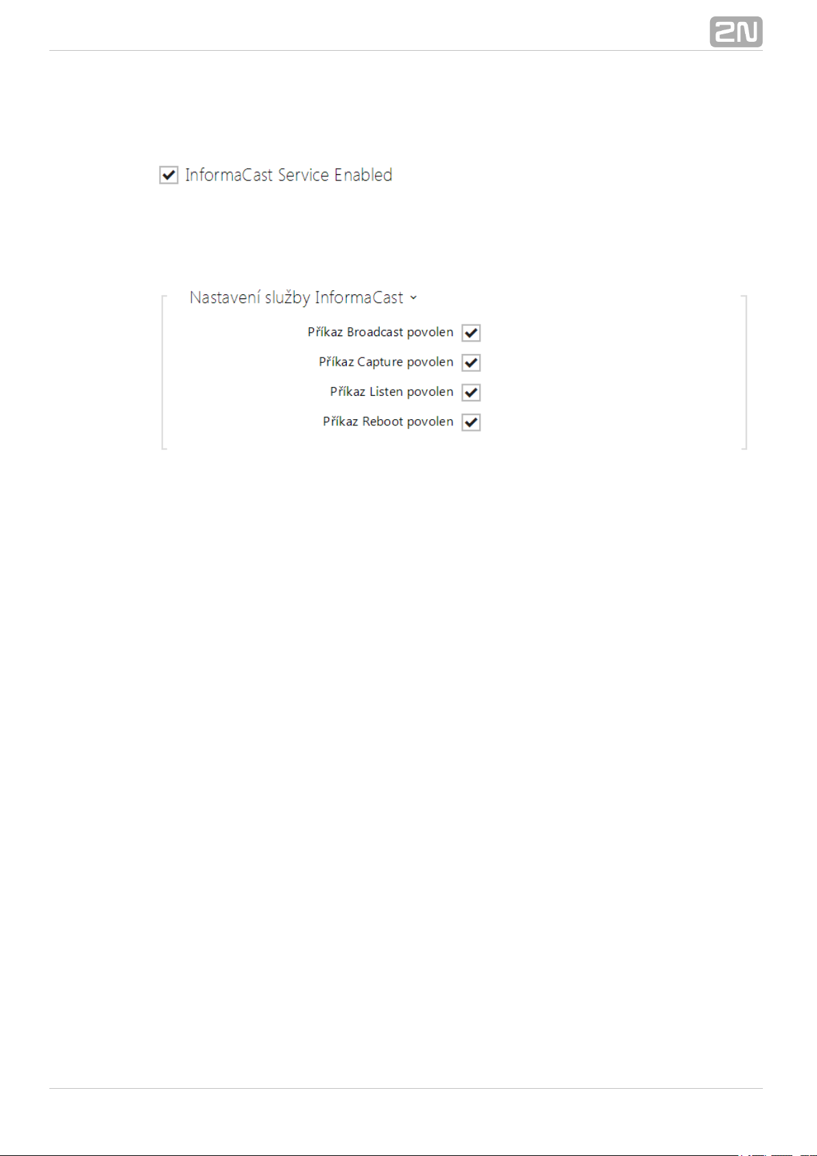
The intercom supports registration with up to 4 Informacast servers at the same time
and setup of up to 6 parallel audio streams.
Informacast service enabled - enable the Informacast service on your intercom
side.
Broadcast enabled - enable the Broadcast command to set up an audio stream sent
from the Informacast server to the intercom.
Capture enabled - enable the Capture command to set up an audio stream sent from
the intercom to the Informacast server.
Listen enabled - enable the Listen command to set up an audio stream sent from
another Informacast client to the intercom.
Reboot enabled - enable the Reboot command to allow the Informacast server to
restart the intercom.
®
762N TELEKOMUNIKACE a.s., www.2n.cz
Page 77

5.4.3 ONVIF
List of Parameters
The intercoms are ONVIF compatible and fully implement the ONVIF2N Helios IP
®
Profile S.
Discovery mode – enable the WS-Discovery function, which allows the other
ONVIF clients to search a compatible device in the LAN. Set the parameter to
to use your intercom as an ONVIF compatible device.Discoverable
User name - set the user name for access to ONVIF.
Password - set the password for access to ONVIF.
a.
b.
c.
d.
Note
Check the following RTSP and JPEG functions for enable to make the
ONVIF function work properly (to gain full compatibility with the third
party equipment):
on the RTSP tabRTSP Server enabled
RTSP tabVideo stream enabled on the
o RTSP tabUDP unicast enabled n the
o JPEG tabSnapshot download enabled n the
®
772N TELEKOMUNIKACE a.s., www.2n.cz
Page 78

Note
Preset authorisation for ONVIF
Username: admin
Password: 2n
®
782N TELEKOMUNIKACE a.s., www.2n.cz
Page 79

5.4.4 E-Mail
To inform the intercom users on all missed and/or successfully completed calls,
configure to send an E-mail after every call to the called user. You can2N Helios IP
®
compile the E-mail subject and message text of your own. If your intercom is equipped
with a camera, you can automatically attach one or more snapshots taken during the
call or ringing.
The intercom sends E-mails to all the users whose valid E-mail addresses are included
in the Phone Book. If the parameter in the Phone Book is empty, E-mails areE-Mail
sent to the default E-mail address.
You can also send E-mails via Automation using the action.Action.SendEmail
List of Parameters
SMTP
SMTP service enabled – enable/disable sending E-mails from the intercom.
Note
The E-mail function is available with the Gold or Enhanced Integration
licence only.
®
792N TELEKOMUNIKACE a.s., www.2n.cz
Page 80

Server address – set the SMTP server address to which E-mails shall be sent.
Server port – specify the SMTP server port. Modify the value only if the SMTP
server setting is substandard. The typical SMTP port value is 25.
Username – enter a valid username for login if the SMTP server requires
authentication, or leave the field empty if not.
Password – enter the SMTP server login password.
User certificate – specify the user certificate and private key for the intercom –
SMTP server communication encryption. Choose one of the three sets of user
certificates and private keys (refer to the Certificates subs.) or keep the Self
setting, in which the certificate automatically generated upon the firstSigned
intercom power up is used.
Deliver in – set the time limit for delivering an E-mail to an inaccessible SMTP
server.
Click to send a testing E-mail to the defined address with the aim to testApply & Test
the functionality of the current E-mail sending setting. Complete the E-mail destination
address in the . The current E-mail sendingdialogue window displayed after the click
state is continuously displayed in the dialogue window for you to detect an E-mail
setting problem if any on the intercom or another network element.
®
802N TELEKOMUNIKACE a.s., www.2n.cz
Page 81

E-Mail
Send E-Mail at – set E-mail sending upon outgoing phone calls. The E-Mail is
sent when the connection is terminated. The following options are available:
Any Outgoing call - an E-mail will be sent upon every outgoing call.
Missed Outgoing call - an E-mail will be sent upon every missed outgoing
call.
Via Automation - no E-mail messages will be sent upon outgoing calls.
Automation have to be set up in order to send an E-mail.
Note
An E-mail can always be sent via Automation.
®
812N TELEKOMUNIKACE a.s., www.2n.cz
Page 82

a.
b.
c.
d.
Sender – enter the sender's E-mail.
Default recipient – typically, the intercom sends E-mail messages to the user
addresses included in the Phone Book. If the Phone Book E-mail parameter is not
completed, the messages are sent to the address included in this parameter. If a
user is not included in the Phone Book or this field, no E-mail is sent.
Message subject – set the E-mail subject to be sent.
Message body – edit the text to be sent. Use the HTML formatting marks in the
text. You can insert special symbols substituting the username, date and time,
intercom identification or called number, which will be replaced with the actual
value before sending. Refer to the table of substitute symbols below:
$User$ Called username
$DateTime$ Current date and time
$DialNumber$Called number
$HeliosId$ Intercom identification
Attach snapshots – enable sending of an attachment including one or more
camera snapshots taken during ringing or calling.
Number of snapshots – set the count of snapshots to be attached to the E-mail
message.
®
822N TELEKOMUNIKACE a.s., www.2n.cz
Page 83

Snapshot resolution – set the snapshot resolution for the images to be sent.
®
832N TELEKOMUNIKACE a.s., www.2n.cz
Page 84

5.4.5 Automation
The intercom provides highly flexible setting options to satisfy variable2N Helios IP
®
user needs. There are situations in which the standard configuration settings (switch or
call modes, e.g.) are insufficient and so offers 2N Helios IP
®
2N Helios IP
®
, a special programmable interface for applications that require complexAutomation
interconnections with third party systems.
Refer to the Configuration Manual for the 2N Helios IP Automation
®
2N Helios IP
®
function and configuration details.Automation
Note
The Automation function is available with the Gold or Enhanced
Integration licence only.
®
842N TELEKOMUNIKACE a.s., www.2n.cz
Page 85

a.
b.
c.
d.
e.
f.
5.4.6 User Sounds
The intercoms provide standard signalling of operational statuses by2N Helios IP
®
tone sequences; refer to the Signalling of Operational Statuses subsection. If you find
the standard sound signalling inconvenient, modify the sounds for the following
statuses:
Ringing before answering call
Call busy tone
Call hang-up
Invalid input
Invalid Phone Book position
Switch activation
You can either completely mute the above-mentioned sounds or replace them with a
sound file of your own simply recorded into the intercom. The sound file must have the
WAV format and use PCM encoding with 8 kHz sampling frequency and 8/16-bit sample
resolution, and the file size may not exceed 128 kB. The maximum file playing time is
limited to approximately 16 seconds for 8-bit and 8 seconds for 16-bit resolution.
You can also play the recorded files via Automation using the Action.PlayUserSound
and, optionally, with the aid of the intercom speaker and/or directly into the phone call.
®
852N TELEKOMUNIKACE a.s., www.2n.cz
Page 86

List of Parameters
Ringing before answering call – set the sound to be played before answering
an incoming call (intercom ring tone).
Call busy tone – set the sound to be played when the called user is busy.
Call hang-up signalling – set the sound to be played upon the call end.
Invalid input signalling – set the sound to be played when an invalid code in
entered (switch/user/profile activation).
Invalid position signalling – set the sound to be played when a quick dial
button is pressed but the corresponding Phone Book position is not programmed.
Switch activation signalling – set the sound to be generated when a switch is
activated. Specify signalling details for each switch; refer to the Switches
subsection.
You can record up to 10 user sound files into the intercom and assign names to them
for convenience.
Press to record a sound file to the intercom. Select a file from your PC via a
dialogue window and push . Press to remove a file. Press to replay theRecord
sound file (locally on your PC).
®
862N TELEKOMUNIKACE a.s., www.2n.cz
Page 87

®
872N TELEKOMUNIKACE a.s., www.2n.cz
Page 88

a.
b.
c.
d.
5.4.7 Web Server
You can configure your intercom using a standard browser which2N Helios IP
®
accesses the integrated web server. Use the secured HTTPS protocol for
communication between the browser and intercom. Having accessed the intercom,
enter the login name and password. The default login name and password are aadmin
nd respectively. We recommend you to change the default password as soon as2n
possible.
The unction is used by the following intercom functions too: Web Server f
JPEG snapshot/MJPEG video download; refer to Streaming.
ONVIF protocol for video streaming, refer to Streaming.
HTTP commands for switch control, refer to Switches.
Event.HttpTrigger in 2N Helios IP Automation, refer to the respective
manual.
The unsecured HTTP protocol can be used for these special communication cases.
List of Parameters
Device name – set the device name to be displayed in the right upper corner of
the web interface, login window and other applications if available (2N Helios IP
®
Manager, 2N Helios IP Network Scanner, etc).®
Web interface language – set the default language for administration web
server login. Use the upper toolbar buttons to change the language temporarily.
®
882N TELEKOMUNIKACE a.s., www.2n.cz
Page 89

Password – set the intercom access password. Press to change the
password. The 8-character password must include one lower-case letter, one
upper-case letter and one digit at least.
HTTP port – set the web server port for HTTP communication. The port setting
will not be applied until the intercom gets restarted.
HTTPS port – set the web server port for HTTPS communication. The port
setting will not be applied until the intercom gets restarted.
HTTPS user certificate – specify the user certificate and private key for the
intercom HTTP server – user web browser communication encryption. Choose
one of the three sets of user certificates and private keys (refer to the
Certificates subsection) or keep the setting, in which the certificateSelfSigned
automatically generated upon the first intercom power up is used.
Remote access enabled – enable remote access to the intercom web server
from off-LAN IP addresses.
Original language – download the original file containing all the user interface
texts in English. The file format is XML; see below.
User language – record, load and remove, if necessary, a user file containing
your own user interface text translations.
®
892N TELEKOMUNIKACE a.s., www.2n.cz
Page 90

<?xml version="1.0" encoding="UTF-8"?>
<strings language="English" languageshort="EN">
<!-- Global enums-->
<s id="enum/error/1">Invalid value!</s>
<s id="enum/bool_yesno/0">NO</s>
<s id="enum/bool_yesno/1">YES</s>
<s id="enum/bool_user_state/0">ACTIVE</s>
<s id="enum/bool_user_state/1">INACTIVE</s>
<s id="enum/bool_profile_state/0">ACTIVE</s>
<s id="enum/bool_profile_state/1">INACTIVE</s>
..
..
..
</strings>
While translating, modify the value of elements only. Do not modify the values.<s> id
The language name specified by the attribute of the element willlanguage <strings>
be available in the selections of the Web interface language parameter. The
abbreviation of the language name specified by the attribute of the languageshort
element will be included in the language list in the right-hand upper corner<strings>
of the window and will be used for a quick language switching.
®
902N TELEKOMUNIKACE a.s., www.2n.cz
Page 91

5.4.8 Audio Test
The intercoms allow you to perform periodical tests of the integrated2N Helios IP
®
speaker and microphone. For the test purpose, the integrated speaker generates one
or more short beeps. The integrated microphone receives the generated tone and the
test is successful if the tone is detected correctly. The test takes approximately 4
seconds. If the test fails (which may be due to an extreme surrounding noise level,
e.g.), a new test is carried out in 10 minutes. The result of the last test can be
displayed in the intercom confirmation interface or processed by the 2N Helios IP
®
Automation.
List of Parameters
Audio test enabled – enable automatic execution of the audio test.
Note
The audio test is available with the Gold or Enhanced Audio licence only.
®
912N TELEKOMUNIKACE a.s., www.2n.cz
Page 92

Test period – set the test period: daily or weekly.
Test start time – set the test starting time in the HH:MM format. We
recommend you to set a time at which a low intercom traffic is expected.
Test now – push the button to start the test immediately regardless of the
current settings.
Test status – this parameter displays the current test status.
Last test time – this parameter displays the time of the last-performed test.
Last test result – this parameter displays the result of the last-performed test.
®
922N TELEKOMUNIKACE a.s., www.2n.cz
Page 93

5.5 System
Here is what you can find in this section:
5.5.1 Network
5.5.2 Date and Time
5.5.3 Licence
5.5.4 Certificates
5.5.5 Auto Provisioning
5.5.6 Syslog
5.5.7 Maintenance
®
932N TELEKOMUNIKACE a.s., www.2n.cz
Page 94

5.5.1 Network
As the intercom is connected to the LAN, make sure that its IP address2N Helios IP
®
has been set correctly or obtained from the LAN DHCP server. Configure the IP address
and DHCP in the subsection.Network
If you use the RADIUS server and 802.1x-based verification of connected equipment,
you can make the intercom use the EAP-MD5 or EAP-TLS authentication. Set this
function in the tab.802.1x
The tab helps you launch capture of incoming and outgoing packets on theTrace
intercom network interface. The file with captured packets can be downloaded for
Wireshark processing, e.g. (www.wireshark.org).
List of Parameters
Network
Use DHCP server – enable automatic obtaining of the IP address from the LAN
DHCP server. If the DHCP server is unavailable or inaccessible in your LAN, use
the manual network settings.
Tip
To know the current IP address of your intercom, use the 2N Helios IP
®
, which can be freely downloaded from , or apply theScanner www.2n.cz
steps described in the Installation Manual of the respective intercom: the
intercom communicates its IP address to you via a voice function.
®
942N TELEKOMUNIKACE a.s., www.2n.cz
Page 95

Static IP address – static IP address of the intercom, which is used together
with the below mentioned parameters if the parameter isUse DHCP Server
disabled.
Network mask – network mask.
Default gateway – address of the default gateway, which provides
communication with off-LAN equipment.
Primary DNS – primary DNS server address for translation of domain names to
IP addresses.
Secondary DNS – secondary DNS server address, which is used in case the
primary DNS is inaccessible.
External IP address – set the public IP address of the router to which your
intercom is connected. If the intercom IP address is public, leave this field blank.
802.1x
Device identity – username (identity) for authentication via EAP-MD5 and
EAP-TLS.
®
952N TELEKOMUNIKACE a.s., www.2n.cz
Page 96

MD5 authentication enabled – enable authentication of network devices via
the 802.1x EAP-MD5 protocol. Do not enable this function if your LAN does not
support 802.1x. If you do so, the intercom will become inaccessible.
Password – enter the access password for EAP-MD5 authentication.
TLS authentication enabled – enable authentication of network devices via the
802.1x EAP-TLS protocol. Do not enable this function if your LAN does not
support 802.1x. If you do so, the intercom will become inaccessible.
Trusted certificate – specify the set of trusted certificates for verification of the
RADIUS server public certificate validity. Choose one of three sets of certificates;
refer to the Certificates subsection. If no trusted certificate is included, the
RADIUS public certificate is not verified.
User certificate – specify the user certificate and private key for verification of
the intercom authorisation to communicate via the 802.1x-secured network
element port in the LAN. Choose one of three sets of user certificates and private
keys; refer to the Certificates subsection.
Trace
In the tab, you can launch capturing of incoming and outgoing packets on theTrace
intercom network interface. The captured packets are stored in a 4 MB buffer. When
the buffer fills up, the oldest packets are overwritten automatically. We recommend
you to lower the video stream transmission rate below 512 kbps while capturing. Press
to start, to stop and to download the packet capture file.
Poznámka
This function is available with the Gold or Enhanced Security licence only.
®
962N TELEKOMUNIKACE a.s., www.2n.cz
Page 97

®
972N TELEKOMUNIKACE a.s., www.2n.cz
Page 98

5.5.2 Date and Time
If you control validity of phone numbers, lock activation codes and similar by time
profiles, make sure that the intercom internal date and time are set correctly.
Most models are equipped with a back-up real-time clock to withstand2N Helios IP
®
up to several days' long power outages. If not equipped with this function, the intercom
loses the real time data upon power outage (or restart). Therefore, if the intercom is
powered up after a rather long period of time (after new intercom installation, e.g.),
time is set to the default value and has to be reset. You can synchronise the intercom
time with your PC anytime by pressing the button.Synchronise
Synchronise the intercom internal time with any available SNTP server if your intercom
is not equipped with a real-time clock.
Practically, the intercom real-time circuit accuracy is approximately ±0,005 %, which
may mean a deviation of 2 minutes per month. Therefore, we recommend you to±
synchronise time with the NTP server to achieve the highest accuracy and reliability.
The intercom sends a query to the NTP server periodically to update its time value.
List of Parameters
Note
The intercom does not need the basiccurrent date and time values for its
function. However, be sure to set these values when you apply time
profiles and display time of listed events (Syslog, used cards, logs
downloaded by HTTP API, etc.).2N Helios IP
®
®
982N TELEKOMUNIKACE a.s., www.2n.cz
Page 99

Synchronise – push the button to synchronise the intercom time value with your PC
time value.
Time zone – set the time zone for the installation site to define time shifts and
winter/summer time transitions.
Time zone rule – if the intercom is installed on a site that it not included in the
parameter, set the time zone rule manually. The rule is applied onlyTime zone
if the parameter is set to .Time zone Manual
Use NTP server – enable the NTP server use for intercom time synchronisation.
NTP server address – set the IP address/domain name of the NTP server used
for your intercom time synchronisation.
®
992N TELEKOMUNIKACE a.s., www.2n.cz
Page 100

5.5.3 Licence
Some functions are available with a valid licence key only. Refer to the2N Helios IP
®
subsection for the list of intercom Model Differences and Function Licensing
licensing options.
List of Parameters
Licence key – enter the valid licence key.
Licence key valid – check whether the used licence key is valid.
Current licence – check current licence type: Basic, Gold or Enhanced.
Enhanced security – check whether the functions activated by the Enhanced
®
1002N TELEKOMUNIKACE a.s., www.2n.cz
 Loading...