


TECHNICAL GUIDE
SPLIT-SYSTEM
AIR CONDITIONERS
13 SEER – R-410A
MODELS: YCJD18 THRU 60
(1.5 THRU 5 NOMINAL TONS, 1 PHASE)
|
ISO 9001 |
LISTED |
Certified Quality |
Management System |
Due to continuous product improvement, specifications are subject to change without notice.
Visit us on the web at www.york.com
Additional rating information can be found at www.ahridirectory.org
364834-YTG-C-0708
DESCRIPTION
The 13 SEER Series condensing unit is the outdoor part of a versatile system of air conditioning. It is designed to be cus- tom-matched with one of UPG’s complete line of evaporator sections, with each serving a specific function. Matching Air Handlers are available for upflow, downflow, or horizontal applications to provide a complete system. Electric Heaters are available, if required. Add-on coils are available for use with upflow, downflow, or horizontal furnaces and air handlers.
WARRANTY
Single Phase Units:
5-year limited parts warranty.
10-year limited compressor warranty.
FEATURES
•QUALITY CONDENSER COILS - The coil is constructed of aluminum microchannel tubing and enhanced aluminum fins for increased efficiency and corrosion protection.
•PROTECTED COMPRESSOR - The compressor is internally protected against high pressure, temperature, and externally by a factory installed high pressure switch. This is accomplished by the simultaneous operation of high pressure relief valve and a temperature sensor which protects the compressor if undesirable operating conditions occur. A liquid line filter-drier further protects the compressor.
•DURABLE FINISH - The cabinet is made of pre-painted steel. The pre-treated galvanized steel provides a better paint to steel bond, which resists corrosion and rust creep. Special primer formulas and matted-textured finish insure less fading when exposed to sunlight.
•LOWER INSTALLED COST - Installation time and costs are reduced by easy power and control wiring connections. Available in sweat connect models only. The unit contains enough refrigerant for matching indoor coils and 15 feet of interconnecting piping. The small base dimension means less space is required on the ground or roof.
•TOP DISCHARGE - The warm air from the top mounted fan is blown up away from the structure and any landscaping. This allows compact location on multi-unit applications.
•LOW OPERATING SOUND LEVEL - The upward air flow carries the normal operating noise away from the living area. The rigid top panel effectively isolates any motor sound. Isolator mounted compressor and the rippled fins of the condenser coil muffle the normal fan motor and compressor operating sounds.
•LOW MAINTENANCE - Long life permanently lubricated motor-bearings need no annual servicing.
•EASY SERVICE ACCESS - Fully exposed refrigerant connections, and a single panel covering the electrical controls make for easy servicing of the unit.
•SECURED SERVICE VALVES - Secured re-usable service valves are provided on both the liquid and vapor sweat connections for ease of evacuating and charging.
•U.L. and C.U.L. listed - approved for outdoor application.
Certified in accordance with the Unitary Small Equipment certification program, which is based on ARI Standard 210/240.
FOR DISTRIBUTION USE ONLY - NOT TO BE USED AT POINT OF RETAIL SALE
364834-YTG-C-0708
Physical and Electrical Data
MODEL |
|
YCJD18 |
YCJD24 |
YCJD30 |
|
YCJD36 |
|
YCJD42 |
YCJD48 |
YCJD60 |
|
S41S1(H) |
S41S1(H) |
S41S1(H) |
|
S41S1(H) |
|
S41S1(H) |
S41S1(H) |
S41S1 |
|
|
|
|
|
|||||||
|
|
|
|
|
|
|
|
|
|
|
Unit Supply Voltage |
|
|
|
208-230V, 1φ, 60Hz |
|
|
|
|||
|
|
|
|
|
|
|
|
|
||
Normal Voltage Range 1 |
|
|
|
|
187 to 252 |
|
|
|
||
Minimum Circuit Ampacity |
10.0 |
12.4 |
14.7 |
|
17.9 |
|
21.5 |
21.1 |
34.3 |
|
|
|
|
|
|
|
|
|
|
|
|
Max. Overcurrent Device Amps 2 |
15 |
20 |
25 |
|
30 |
|
35 |
35 |
60 |
|
Min. Overcurrent Device Amps 3 |
15 |
15 |
15 |
|
20 |
|
25 |
25 |
35 |
|
Compressor Type |
|
Rotary |
Recip |
Recip |
|
Recip |
|
Recip |
Recip |
Scroll |
|
|
|
|
|
|
|
|
|
|
|
Compressor Amps |
Rated Load |
7.6 |
9.3 |
10.6 |
|
13.1 |
|
16.0 |
15.7 |
26.2 |
|
|
|
|
|
|
|
|
|
|
|
Locked Rotor |
40.0 |
43.0 |
54.0 |
|
74 |
|
84 |
84 |
150 |
|
|
|
|
|
|
|
|
|
|
|
|
Crankcase Heater |
|
No |
No |
No |
|
No |
|
No |
No |
No |
|
|
|
|
|
|
|
|
|
|
|
Fan Motor Amps |
Rated Load |
0.5 |
0.8 |
1.4 |
|
1.5 |
|
1.5 |
1.5 |
1.5 |
|
|
|
|
|
|
|
|
|
|
|
Fan Diameter Inches |
17.5 |
17.5 |
17.5 |
|
22 |
|
22 |
22 |
24 |
|
|
|
|
|
|
|
|
|
|
|
|
|
Rated HP |
1/12 |
1/8 |
1/4 |
|
1/4 |
|
1/4 |
1/4 |
1/4 |
Fan Motor |
|
|
|
|
|
|
|
|
|
|
Nominal RPM |
1100 |
1075 |
1100 |
|
850 |
|
850 |
850 |
850 |
|
|
|
|
|
|
|
|
|
|
|
|
|
Nominal CFM |
1400 |
1950 |
2050 |
|
3200 |
|
2950 |
2950 |
3600 |
|
|
|
|
|
|
|
|
|
|
|
|
Face Area Sq. Ft. |
9.60 |
9.60 |
9.60 |
|
13.07 |
|
14.16 |
14.16 |
18.68 |
Coil |
|
|
|
|
|
|
|
|
|
|
Rows Deep |
1 |
1 |
1 |
|
1 |
|
1 |
1 |
1 |
|
|
|
|
|
|
|
|
|
|
|
|
|
Fin / Inches |
23 |
23 |
23 |
|
23 |
|
23 |
23 |
23 |
|
|
|
|
|
|
|
|
|
|
|
Liquid Line Set OD (Field Installed) |
3/8 |
3/8 |
3/8 |
|
3/8 |
|
3/8 |
3/8 |
3/8 |
|
|
|
|
|
|
|
|
|
|
|
|
Vapor Line Set OD (Field Installed) |
5/8 |
3/4 |
3/4 |
|
3/4 |
|
7/8 |
7/8 |
7/8 |
|
|
|
|
|
|
|
|
|
|
|
|
Unit Charge (Lbs. - Oz.) 4 |
3 - 3 |
3 - 13 |
3 - 14 |
|
4 - 9 |
|
4 - 5 |
4 - 9 |
5 - 6 |
|
Charge Per Foot, Oz. |
0.58 |
0.62 |
0.62 |
|
0.62 |
|
0.67 |
0.67 |
0.67 |
|
|
|
|
|
|
|
|
|
|
|
|
Operating Weight Lbs. |
97 |
129 |
131 |
|
145 |
|
173 |
173 |
195 |
|
|
|
|
|
|
|
|
|
|
|
|
Models with “H” on the end of the model number have a factory installed start kits.
1.Rated in accordance with ARI Standard 110, utilization range “A”.
2.Dual element fuses or HACR circuit breaker. Maximum allowable overcurrent protection.
3.Dual element fuses or HACR circuit breaker. Minimum recommended overcurrent protection.
4.The Unit Charge is correct for the outdoor unit, matched indoor coil and 15 feet of refrigerant tubing. For tubing lengths other than 15 feet, add or subtract the amount of refrigerant, using the difference in length multiplied by the per foot value.
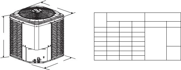
|
All dimensions are in inches. They are subject to change |
||||||
|
without notice. Certified dimensions will be provided upon |
||||||
C |
request. |
|
|
|
|
|
|
|
Unit |
|
Dimensions |
|
Refrigerant Connection |
||
|
|
(Inches) |
|
|
Service Valve Size |
||
|
Model |
A1 |
B |
|
C |
Liquid |
Vapor |
|
|
|
|||||
|
18 |
28 |
23-1/2 23-1/2 |
|
|
||
A |
24 |
28 |
23-1/2 |
23-1/2 |
|
3/4” |
|
30 |
28 |
23-1/2 23-1/2 |
|
||||
|
|
|
|||||
|
36 |
28 |
29 |
|
29 |
3/8” |
|
|
42 |
30 |
29 |
|
29 |
|
|
|
48 |
30 |
29 |
|
29 |
|
7/8” |
|
60 |
32 |
33-5/8 |
33-5/8 |
|
|
|
B |
1. Including Fan Guard. |
|
2 |
Johnson Controls Unitary Products |

364834-YTG-C-0708
Additional R-410A Charge / Orifice Size for Various Matched Systems
Outdoor Unit |
YCJD18 |
YCJD24 |
YCJD30 |
YCJD36 |
YCJD42 |
YCJD48 |
YCJD60 |
|
S41S1(H) |
S41S1(H) |
S41S1(H) |
S41S1(H) |
S41S1(H) |
S41S1(H) |
S41S1 |
||
|
||||||||
|
|
|
|
|
|
|
|
|
Required Orifice or TXV 1,2 |
0.048 / 902 |
0.055 / 902 |
0.061 / 907 |
0.065 / 903 |
0.075 / 903 |
0.073 / 904 |
0.087 / 905 |
|
Factory Charge, lbs-oz |
3 - 3 |
3 - 13 |
3 - 14 |
4 - 9 |
4 - 5 |
4 - 9 |
5 - 6 |
|
|
|
|
|
|
|
|
|
|
Indoor Coil3,4 |
|
|
Additional Charge, Oz |
|
|
|||
FC/MC/PC/UC18A3X |
48 + 0 |
– |
– |
– |
– |
– |
– |
|
902 + 0 |
– |
– |
– |
– |
– |
– |
||
|
||||||||
FC/MC/PC/UC18B3X |
48 + 0 |
– |
– |
– |
– |
– |
– |
|
902 + 0 |
– |
– |
– |
– |
– |
– |
||
|
||||||||
FC/MC/PC32A3X |
– |
55 + 4 |
61 + 0 |
– |
– |
– |
– |
|
– |
902 + 4 |
907 + 0 |
– |
– |
– |
– |
||
|
||||||||
FC/MC/PC35B3X |
– |
55 + 4 |
61 + 0 |
– |
– |
– |
– |
|
– |
902 + 4 |
907 + 0 |
– |
– |
– |
– |
||
|
||||||||
FC/MC/PC35C3X |
– |
55 + 4 |
61 + 0 |
– |
– |
– |
– |
|
– |
902 + 4 |
907 + 0 |
– |
– |
– |
– |
||
|
||||||||
FC/MC/PC/UC36A3X |
– |
55 + 0 |
– |
– |
– |
– |
– |
|
– |
902 + 0 |
– |
– |
– |
– |
– |
||
|
||||||||
FC/MC/PC/UC36B3X |
– |
55 + 0 |
– |
– |
– |
– |
– |
|
– |
902 + 0 |
– |
– |
– |
– |
– |
||
|
||||||||
FC/MC/PC/UC36C3X |
– |
55 + 0 |
– |
– |
– |
– |
– |
|
– |
902 + 0 |
– |
– |
– |
– |
– |
||
|
||||||||
FC/MC/PC37A3X |
– |
55 + 4 |
61 + 2 |
65 + 0 |
– |
– |
– |
|
– |
902 + 4 |
907 + 2 |
903 + 0 |
– |
– |
– |
||
|
||||||||
FC/MC/PC43B3X |
– |
55 + 4 |
61 + 2 |
65 + 0 |
75 + 0 |
– |
– |
|
– |
902 + 4 |
907 + 2 |
903 + 0 |
903 + 0 |
– |
– |
||
|
||||||||
FC/MC/PC43C3X |
– |
55 + 4 |
61 + 2 |
65 + 0 |
75 + 0 |
– |
– |
|
– |
902 + 4 |
907 + 2 |
903 + 0 |
903 + 0 |
– |
– |
||
|
||||||||
FC/MC/PC/UC48C3X |
– |
– |
– |
65 + 8 |
75 + 2 |
73 + 4 |
– |
|
– |
– |
– |
903 + 8 |
903 + 2 |
904 + 4 |
– |
||
|
||||||||
FC/MC/PC/UC48D3X |
– |
– |
– |
65 + 8 |
75 + 2 |
73 + 4 |
– |
|
– |
– |
– |
903 + 8 |
903 + 2 |
904 + 4 |
– |
||
|
||||||||
FC/MC/PC/UC60D3X |
– |
– |
– |
– |
– |
73 + 0 |
87 + 0 |
|
– |
– |
– |
– |
– |
904 + 0 |
905 + 0 |
||
|
||||||||
FC/MC62D3X |
– |
– |
– |
– |
– |
– |
87 + 4 |
|
– |
– |
– |
– |
– |
– |
905 + 4 |
||
|
||||||||
HC18A3X |
48 + 0 |
– |
– |
– |
– |
– |
– |
|
902 + 0 |
– |
– |
– |
– |
– |
– |
||
|
||||||||
HC30A3X |
– |
55 + 0 |
– |
– |
– |
– |
– |
|
– |
902 + 0 |
– |
– |
– |
– |
– |
||
|
||||||||
HC36B3X |
– |
55 + 4 |
61 + 0 |
– |
– |
– |
– |
|
– |
902 + 4 |
907 + 0 |
– |
– |
– |
– |
||
|
||||||||
HC42C3X |
– |
55 + 4 |
61 + 2 |
65 + 0 |
75 + 0 |
– |
– |
|
– |
902 + 4 |
907 + 2 |
903 + 0 |
903 + 0 |
– |
– |
||
|
||||||||
HC60D3X |
– |
– |
– |
– |
– |
– |
87 + 0 |
|
– |
– |
– |
– |
– |
– |
905 + 0 |
||
|
||||||||
AHP18B3X |
48 + 0 |
– |
– |
– |
– |
– |
– |
|
902 + 0 |
– |
– |
– |
– |
– |
– |
||
|
||||||||
AHP30B3X |
– |
55 + 4 |
61 + 0 |
– |
– |
– |
– |
|
– |
902 + 4 |
907 + 0 |
– |
– |
– |
– |
||
|
||||||||
AHP36C3X |
– |
– |
61 + 2 |
65 + 0 |
– |
– |
– |
|
– |
– |
907 + 2 |
903 + 0 |
– |
– |
– |
||
|
||||||||
AHP42C3X |
– |
– |
– |
65 + 0 |
75 + 0 |
– |
– |
|
– |
– |
– |
903 + 0 |
903 + 0 |
– |
– |
||
|
||||||||
Johnson Controls Unitary Products |
3 |
364834-YTG-C-0708
Additional R-410A Charge / Orifice Size for Various Matched Systems (Continued)
Outdoor Unit |
YCJD18 |
YCJD24 |
YCJD30 |
YCJD36 |
YCJD42 |
YCJD48 |
YCJD60 |
|||
S41S1(H) |
S41S1(H) |
S41S1(H) |
S41S1(H) |
S41S1(H) |
S41S1(H) |
S41S1 |
||||
|
|
|
||||||||
|
|
|
|
|
|
|
|
|
|
|
Required Orifice or TXV 1,2 |
0.048 / 902 |
0.055 / 902 |
0.061 / 907 |
0.065 / 903 |
0.075 / 903 |
0.073 / 904 |
0.087 / 905 |
|||
Factory Charge, lbs-oz |
3 - 3 |
3 - 13 |
3 - 14 |
4 - 9 |
4 - 5 |
4 - 9 |
5 - 6 |
|||
|
|
|
|
|
|
|
|
|
|
|
Indoor Coil3,4 |
|
|
Additional Charge, Oz |
|
|
|||||
AHP/SHP60D3X |
– |
– |
– |
– |
– |
73 + 0 |
87 + 0 |
|||
– |
– |
– |
– |
– |
904 + 0 |
905 + 0 |
||||
|
|
|
||||||||
AV36C3X |
|
|
– |
55 + 4 |
61 + 2 |
65 + 0 |
– |
– |
– |
|
|
|
– |
902 + 4 |
907 + 2 |
903 + 0 |
– |
– |
– |
||
|
|
|
||||||||
AV/SV48D3X |
– |
– |
– |
– |
– |
73 + 0 |
– |
|||
– |
– |
– |
– |
– |
904 + 0 |
– |
||||
|
|
|
||||||||
AV60D3X |
|
|
– |
– |
– |
– |
– |
– |
87 + 0 |
|
|
|
– |
– |
– |
– |
– |
– |
905 + 0 |
||
|
|
|
||||||||
F4FP024 |
|
|
48 + 0 |
– |
– |
– |
– |
– |
– |
|
See Caution below |
|
|
|
|
|
|
|
|
||
902 + 0 |
– |
– |
– |
– |
– |
– |
||||
|
|
|
||||||||
F4FP036 |
|
|
– |
55 + 0 |
– |
– |
– |
– |
– |
|
See Caution below |
|
|
|
|
|
|
|
|
||
– |
902 + 0 |
– |
– |
– |
– |
– |
||||
|
|
|
||||||||
F4FP040 |
|
|
– |
– |
61 + 0 |
– |
– |
– |
– |
|
See Caution below |
|
|
|
|
|
|
|
|
||
– |
– |
907 + 0 |
– |
– |
– |
– |
||||
|
|
|
||||||||
F5FP048 |
|
|
– |
– |
– |
65 + 8 |
75 + 2 |
73 + 4 |
– |
|
See Caution below |
|
|
|
|
|
|
|
|
||
– |
– |
– |
903 + 8 |
903 + 2 |
904 + 4 |
– |
||||
|
|
|
||||||||
F5FP060 |
|
|
– |
– |
– |
– |
– |
73 + 0 |
87 + 0 |
|
See Caution below |
|
|
|
|
|
|
|
|
||
– |
– |
– |
– |
– |
904 + 0 |
905 + 0 |
||||
|
|
|
||||||||
F4FV060 |
|
|
– |
– |
– |
– |
– |
73 + 0 |
87 + 0 |
|
See Caution below |
|
|
|
|
|
|
|
|
||
– |
– |
– |
– |
– |
904 + 0 |
905 + 0 |
||||
|
|
|
||||||||
FOOTNOTES: |
|
|
|
|
|
|
|
|||
1.For applications requiring a TXV use 1TVM900 series kit.
2.Approved orifice shipped with outdoor unit.
3.Systems matched with furnace or air handlers not equipped with blower-off delays may require blower Time Delay Kit 2FD06700224.
4.PC coils cannot be used in downflow or horizontal applications. FC coils cannot be used in horizontal applications.
PROCEDURES:
1.Unit factory charge listed on the unit nameplate includes refrigerant for the condenser, the smallest evaporator and 15 feet of interconnecting line tubing.
2.Verify the TXV or orifice and additional charge required for specific evaporator coil in the system using the above table.
3.Additional charge for the amount of interconnecting line tubing greater than 15 feet at the rate specified in Physical and Electrical Data Table.
4.For TXV match charge weight needs to be weighed in for specififc coil match and lineset length.
5.Permanently mark the unit nameplate with the total system charge. Total System Charge = Base Charge (as shipped) + adder for evaporator + adder for line set.
Models 12-48 require start kits for TXV matches. Models with “H” on the end of the model number have factory installed start kits. For models without an “H” refer to tech guide for kit number reference.
F*FP Air Handlers come with a factory installed R-22 TXV which MUST BE CHANGED OUT to R-410A TXV or an orifice for proper operation. If the TXV is not changed out system damage will occur.
4 |
Johnson Controls Unitary Products |
364834-YTG-C-0708
COOLING CAPACITY - With Air Handler Coils
UNIT |
|
AIR HANDLER |
|
COIL |
|
|
COOLING |
|
|
|
|
|
|
|
RATED |
NET MBH |
|
|
|||
MODEL |
|
MODEL |
|
W |
MODEL1 |
SEER |
EER |
|||
|
|
CFM |
TOTAL |
SENS. |
||||||
|
|
|
|
|
|
|
|
|||
|
|
|
|
|
13 SEER AC WITH MA |
|
|
|
|
|
YCJD18S41S1(H) |
|
MA08B |
|
17 |
FC/MC18B |
600 |
17.5 |
12.9 |
13.00 |
11.00 |
|
|
MA08B |
|
17 |
FC/MC36B |
800 |
24.0 |
16.7 |
13.00 |
11.00 |
YCJD24S41S1(H) |
|
|
|
|
|
|
|
|
|
|
|
MA08B |
|
17 |
FC/MC35B |
800 |
24.0 |
16.7 |
13.00 |
11.00 |
|
|
|
MA08B |
|
17 |
FC/MC43B |
800 |
24.0 |
16.7 |
13.00 |
11.00 |
YCJD30S41S1(H) |
|
MA12B |
|
17 |
FC/MC35B |
1000 |
29.0 |
21.0 |
13.00 |
11.00 |
|
MA12B |
|
17 |
FC/MC43B |
1000 |
29.0 |
21.0 |
13.00 |
11.00 |
|
|
|
|
||||||||
YCJD36S41S1(H) |
|
MA12B |
|
17 |
FC/MC43B |
1200 |
35.0 |
24.8 |
13.00 |
11.00 |
|
MA14D |
|
24 |
FC/MC48D |
1200 |
35.0 |
24.8 |
13.00 |
11.00 |
|
|
|
|
||||||||
|
|
MA16C |
|
21 |
FC/MC43C |
1400 |
42.0 |
29.2 |
13.00 |
11.00 |
YCJD42S41S1(H) |
|
|
|
|
|
|
|
|
|
|
|
MA14D |
|
24 |
FC/MC48D |
1400 |
42.0 |
29.2 |
13.00 |
11.00 |
|
|
|
MA16C |
|
21 |
FC/MC48C |
1400 |
42.0 |
29.2 |
13.00 |
11.00 |
|
|
MA16C |
|
21 |
FC/MC48C |
1600 |
48.0 |
34.4 |
13.00 |
11.00 |
YCJD48S41S1(H) |
|
MA20D |
|
24 |
FC/MC48D |
1600 |
48.0 |
34.4 |
13.00 |
11.00 |
|
MA16C |
|
21 |
FC60C |
1600 |
48.0 |
34.4 |
13.00 |
11.00 |
|
|
|
|
||||||||
|
|
MA20D |
|
24 |
FC/MC60D |
1600 |
48.0 |
34.4 |
13.00 |
11.00 |
YCJD60S41S1 |
|
MA20D |
|
24 |
FC/MC60D |
1800 |
57.0 |
38.5 |
13.00 |
11.00 |
|
MA20D |
|
24 |
FC/MC62D |
1800 |
57.0 |
38.5 |
13.00 |
11.00 |
|
|
|
|
||||||||
|
|
|
|
13 SEER AC WITH MV - VARIABLE SPEED |
|
|
|
|||
YCJD18S41S1(H) |
|
MV12B |
|
17 |
FC/MC18B |
600 |
17.5 |
13.3 |
14.00 |
12.50 |
|
|
MV12B |
|
17 |
FC/MC36B |
800 |
24.0 |
17.4 |
14.00 |
12.00 |
YCJD24S41S1(H) |
|
|
|
|
|
|
|
|
|
|
|
MV12B |
|
17 |
FC/MC35B |
800 |
24.0 |
17.4 |
14.00 |
12.00 |
|
|
|
MV12B |
|
17 |
FC/MC43B |
800 |
24.0 |
17.3 |
14.00 |
12.00 |
|
|
MV12B |
|
17 |
FC/MC35B |
1000 |
29.0 |
21.6 |
14.00 |
12.00 |
YCJD30S41S1(H) |
|
MV16C |
|
21 |
FC/MC35C |
1000 |
30.0 |
21.6 |
14.00 |
12.00 |
|
MV12B |
|
17 |
FC/MC43B |
1000 |
29.0 |
21.6 |
14.00 |
12.00 |
|
|
|
|
||||||||
|
|
MV16C |
|
21 |
FC/MC43C |
1000 |
30.0 |
21.6 |
14.00 |
12.00 |
|
|
MV16C |
|
21 |
FC/MC43C |
1200 |
36.0 |
25.4 |
14.00 |
12.00 |
YCJD36S41S1(H) |
|
MV16C |
|
21 |
FC/MC48C |
1200 |
36.0 |
25.4 |
14.00 |
12.00 |
|
MV20D |
|
24 |
FC/MC48D |
1200 |
36.0 |
25.6 |
14.00 |
12.00 |
|
|
|
|
||||||||
|
|
MV12D |
|
24 |
FC/MC48D |
1135 |
35.0 |
25.4 |
14.00 |
12.00 |
|
|
MV16C |
|
21 |
FC/MC43C |
1400 |
42.0 |
30.0 |
13.50 |
12.00 |
YCJD42S41S1(H) |
|
|
|
|
|
|
|
|
|
|
|
MV16C |
|
21 |
FC/MC48C |
1400 |
42.0 |
30.0 |
13.50 |
12.00 |
|
|
|
MV20D |
|
24 |
FC/MC48D |
1400 |
42.0 |
30.0 |
14.00 |
12.00 |
|
|
MV16C |
|
21 |
FC/MC48C |
1600 |
48.0 |
35.0 |
13.50 |
12.00 |
YCJD48S41S1(H) |
|
|
|
|
|
|
|
|
|
|
|
MV20D |
|
24 |
FC/MC48D |
1600 |
48.0 |
35.0 |
13.50 |
12.00 |
|
|
|
MV20D |
|
24 |
FC/MC60D |
1600 |
48.0 |
35.0 |
13.50 |
12.00 |
YCJD60S41S1 |
|
MV20D |
|
24 |
FC/MC60D |
1800 |
57.0 |
38.5 |
13.00 |
11.00 |
|
MV20D |
|
24 |
FC/MC62D |
1800 |
57.0 |
38.5 |
13.00 |
11.00 |
|
|
|
|
||||||||
|
|
13 SEER AC WITH AV / SV / F*FV - VARIABLE SPEED |
|
|
|
|||||
YCJD24S41S1(H) |
|
AV36 |
|
21 |
– |
765 |
24.0 |
17.4 |
14.00 |
12.00 |
YCJD30S41S1(H) |
|
AV36 |
|
21 |
– |
1015 |
30.0 |
21.8 |
14.00 |
12.00 |
YCJD36S41S1(H) |
|
AV36 |
|
21 |
– |
1270 |
35.0 |
25.2 |
14.00 |
12.00 |
|
|
AV/SV48 |
|
24 |
– |
1610 |
48.0 |
35.0 |
13.50 |
12.00 |
YCJD48S41S1(H) |
|
AV/SV60 |
|
24 |
– |
1655 |
48.0 |
35.0 |
13.50 |
12.00 |
|
|
F4FV060 |
|
24 |
– |
1600 |
48.0 |
34.4 |
14.00 |
11.50 |
YCJD60S41S1 |
|
AV/SV60 |
|
24 |
– |
1765 |
58.0 |
39.0 |
13.50 |
11.00 |
|
F4FV060 |
|
24 |
– |
1780 |
57.0 |
38.5 |
13.50 |
11.00 |
|
|
|
|
||||||||
For Notes See Page 6. |
|
|
|
|
|
|
|
|
|
|
Johnson Controls Unitary Products |
5 |

364834-YTG-C-0708
COOLING CAPACITY - With Air Handler Coils (Continued)
UNIT |
AIR HANDLER |
|
COIL |
|
|
|
COOLING |
|
|
|
|
|
|
RATED |
|
NET MBH |
|
|
|||
MODEL |
MODEL |
|
W |
MODEL1 |
|
SEER |
EER |
|||
|
CFM |
|
TOTAL |
SENS. |
||||||
|
|
|
|
|
|
|
|
|||
|
|
|
13 |
SEER AC WITH AHP |
/ SHP / F*FP |
|
|
|
|
|
YCJD18S41S1(H) |
AHP18 |
|
17 |
– |
650 |
|
17.5 |
12.9 |
13.00 |
11.00 |
F4FP024 |
|
18 |
– |
600 |
|
17.5 |
12.9 |
13.00 |
11.00 |
|
|
|
|
||||||||
YCJD24S41S1(H) |
AHP30 |
|
17 |
– |
795 |
|
24.0 |
16.8 |
13.00 |
11.00 |
F4FP036 |
|
21.5 |
– |
800 |
|
24.0 |
16.7 |
13.00 |
11.00 |
|
|
|
|
||||||||
|
AHP30 |
|
17 |
– |
1015 |
|
29.0 |
21.0 |
13.00 |
11.00 |
YCJD30S41S1(H) |
|
|
|
|
|
|
|
|
|
|
AHP36 |
|
21 |
– |
1040 |
|
29.0 |
21.0 |
13.00 |
11.00 |
|
|
F4FP040 |
|
18 |
– |
1050 |
|
29.0 |
21.0 |
13.00 |
11.00 |
|
AHP36 |
|
21 |
– |
1235 |
|
35.0 |
24.8 |
13.00 |
11.00 |
YCJD36S41S1(H) |
|
|
|
|
|
|
|
|
|
|
AHP42 |
|
21 |
– |
1255 |
|
35.0 |
24.8 |
13.00 |
11.00 |
|
|
F5FP048 |
|
24 |
– |
1235 |
|
35.0 |
24.8 |
13.00 |
11.00 |
YCJD42S41S1(H) |
AHP42 |
|
21 |
– |
1485 |
|
41.0 |
29.2 |
13.00 |
11.00 |
F5FP048 |
|
24 |
– |
1455 |
|
41.0 |
29.2 |
13.00 |
11.00 |
|
|
|
|
||||||||
|
AHP/SHP48 |
|
24 |
– |
1675 |
|
48.0 |
34.4 |
13.00 |
11.00 |
YCJD48S41S1(H) |
AHP/SHP60 |
|
24 |
– |
1600 |
|
48.0 |
35.0 |
13.50 |
11.00 |
F5FP048 |
|
24 |
– |
1600 |
|
48.0 |
34.4 |
13.00 |
11.00 |
|
|
|
|
||||||||
|
F5FP060 |
|
24 |
– |
1600 |
|
48.0 |
34.4 |
13.00 |
11.00 |
YCJD60S41S1 |
AHP/SHP60 |
|
24 |
– |
1850 |
|
57.0 |
38.5 |
13.00 |
11.00 |
F5FP060 |
|
24 |
– |
1900 |
|
57.0 |
38.5 |
13.00 |
11.00 |
|
|
|
|
||||||||
Rated in accordance with DOE test procedures (Federal Register 12-27-79 and 3-18-88) and ARI Standards 210. Cooling MBH based on 80°F entering air temperature, 50% RH, and rated air flow.
EER (Energy Efficiency Ratio) is the total cooling output in BTU’s at 95°F outdoor ambient divided by the total electric power in watt-hours at those conditions. SEER (Seasonal Energy Efficiency Ratio) is the total cooling output in BTU’s during a normal annual usage period for cooling divided by the total electric power input in watt-hours during the same period.
1. MC coils available with a factory installed horizontal drain pan. See price pages for specific model number.
— = Not applicable.
6 |
Johnson Controls Unitary Products |
 Loading...