


 Loading...
FORM 160.80-EG1 (808)
Model YS Rotary Screw Liquid Chillers
Design Level E
Rated in Accordance with the latest edition of ARI
STANDARD 550/590
100 thru 675 tons
(315 thru 2375 KW) R-22 and R-134a

TABLE OF CONTENTS
|
PAGE |
INTRODUCTION............................................................ |
3 |
RATINGS....................................................................... |
4 |
OptiView CONTROL CENTER................................... |
5 |
MECHANICAL SPECIFICATIONS................................. |
13 |
ACCESSORIES & MODIFICATIONS............................ |
17 |
UNIT COMPONENTS.................................................... |
19 |
APPLICATION DATA...................................................... |
20 |
DIMENSIONS – STD..................................................... |
28 |
S0-S3 Compressor.................................................... |
28 |
S4 & S5 Compressor ................................................ |
29 |
Compact Water Box Nozzle Arrangements............... |
30 |
Floor Layout............................................................... |
31 |
Cooler Nozzle Arrangements..................................... |
32 |
Condenser Nozzle Arrangements.............................. |
34 |
WEIGHTS – STD........................................................... |
36 |
DIMENSIONS – METRIC............................................... |
38 |
S0-S3 Compressor.................................................... |
38 |
S4 & S5 Compressor ................................................ |
39 |
Compact Water Box Nozzle Arrangements............... |
40 |
Floor Layout............................................................... |
41 |
Cooler Nozzle Arrangements..................................... |
42 |
Condenser Nozzle Arrangements.............................. |
44 |
WEIGHTS – METRIC..................................................... |
46 |
GUIDE SPECIFICATIONS............................................. |
48 |
Metric Conversion tABLES.................................. |
53 |
|
LIST OF TABLES |
|
TABLE |
|
PAGE |
NO. |
|
|
1 |
Water Flow Rate Limits.................. |
20 |
2 |
Motor Voltage Variations................ |
23 |
3 |
60 Hz Electrical Data...................... |
25 |
4 |
Motor Starters................................ |
25 |
5 |
50 Hz Electrical Data...................... |
26 |
6Available Compressor/Shell/ Motor Combinations
(R-22 & R-134a)............................. |
26 |
7Available Compressor/Shell/ Motor Combinations
(50 Hz, R-134a Only)..................... |
27 |
NOMENCLATURE
The model number denotes the following characteristics of the unit:
|
|
|
|
|
|
YS BB |
BA S0 – CF E S |
|||||||||||||||||||||||||
Model |
|
|
|
|
|
|
|
|
|
|
|
|
|
|
|
|
|
|
|
|
|
|
|
|
|
|
|
|
|
|
|
Special Features |
|
|
|
|
|
|
|
|
|
|
|
|
|
|
|
|
|
|
|
|
|
|
|
|
|
|
|
|
|
|
|
||
Cooler Code |
|
|
|
|
|
|
|
|
|
|
|
|
|
|
|
|
|
|
|
|
|
|
|
|
|
|
|
|
|
|
Design Level |
|
|
|
|
|
|
|
|
|
|
|
|
|
|
|
|
|
|
|
|
|
|
|
|
|
|
|
|
|
|
|
|||
|
Condenser Code |
|
|
|
|
|
|
|
|
|
|
|
|
|
|
|
|
|
|
|
|
|
|
|
|
|
|
Motor Code |
||||
|
|
|
|
|
|
|
|
|
|
|
|
|
|
|
|
|
|
|
|
|
|
|
|
|
|
|
|
|||||
|
|
|
|
|
|
|
|
|
|
|
|
|
|
|
|
|
|
|
|
|
|
|
|
|
|
|||||||
|
Compressor Code |
|
|
|
|
|
|
|
|
|
|
|
|
|
|
|
|
|
|
|
|
|
|
|
Power Supply: |
|||||||
|
|
|
|
|
|
|
|
|
|
|
|
|
|
|
|
|
|
|
|
|
|
|
|
|||||||||
|
|
|
|
|
|
|
|
|
|
|||||||||||||||||||||||
|
|
|
|
|
|
|
|
|
|
|
|
|
|
|
|
|
|
|
|
|
|
|
|
|
|
|
|
|
– for 60 Hz |
|||
|
|
|
|
|
|
|
|
|
|
|
|
|
|
|
|
|
|
|
|
|
|
|
|
|
|
|
|
|
5 for 50 Hz |
|||
|
|
|
|
|
|
|
|
|
|
|
|
|
|
|
|
|
|
|
|
|
|
|
|
|
|
|
|
|
|
JOHNSON CONTROLS |
||

Introduction
FORM 160.80-EG1 (808)
The YORK Millennium YS Chiller offers a complete combination of features for total owner satisfaction.
MATCHED COMPONENTS MAXIMIZE EFFICIENCY
Actual chiller efficiency cannot be determined by analyzing the theoretical efficiency of any one chiller component. It requires a specific combination of heat exchanger, compressor, and motor performance to achieve the lowest system kW/Ton. YORK Millennium chiller technology matches chiller system components to provide maximum chiller efficiency under actual – not just theoretical – operating conditions.
Real-world energy performance
Johnson Controls pioneered the term “Real-World Energy” to illustrate the energy-saving potential of focusing on chiller performance during off-design conditions. Off-de- sign is not only part load, but full load operation as well, with reduced entering condenser water temperatures (ECWTs). This is where chillers operate 99% of the time, and where operating costs add up.
The YS Millennium chillers are the only chillers designed to operate on a continuous basis with cold ECWT and full condenser flow at all load points, taking full advantage of Real-World conditions. This type of operation benefits the cooling tower as well; reducing cycling of the fan motor and ensuring good coverage of the cooling fill.
YORK Millennium chillers offer the most efficient Real-
World operation of any chiller, meaning lower operating costs and an excellent return on your chiller investment.
OPEN DRIVE DESIGN
Hermetic motor burnout can cause catastrophic damage to a chiller. The entire chiller must be cleaned, and the refrigerant replaced. YORK Millennium screw chillers eliminate this risk by utilizing air cooled motors. Refrigerant never comes in contact with the motor, preventing contamination of the rest of the chiller.
Insurance companies that offer policies on large air conditioning equipment often consider air cooled motors a significant advantage over hermetic refrigerant cooled units.
HIGH EFFICIENCY HEAT EXCHANGERS
Millennium chiller heat exchangers offer the latest tech nology in heat transfer surface design to give you maxi mum efficiency and compact design. Water side and refrigerant side design enhancements minimize both energy consumption and tube fouling.
FACTORY PACKAGING REDUCES FIELD LABOR COSTS
YORK Millennium screw chillers are designed to keep installation costs low. Where installation access is not a problem, the unit can be shipped completely packaged, requiring minimal piping and wiring to complete the installation.
For those units utilizing a factory installed Solid State Starter, the three power leads provide all power to the chiller and its auxiliaries.
TAKE ADVANTAGE OF COLDER COOLING TOWER WATER TEMPERATURES
YORK Millennium screw chillers are designed to take full advantage of colder cooling tower water temperatures, which are naturally available during most operating hours. Considerable energy savings are available by letting tower water temperature drop, rather than artificially holding it above 75°F (23.9°C), especially at low load, as some chillers require.
U.L. ACCEPTANCE – YOUR ASSURANCE OF RELIABILITY
YORK Millennium screw chillers are approved for listing by Underwriter’s Laboratories for the United States and Canada. Recognition of safety and reliability is your assurance of trouble free performance in day to-day building operation.
JOHNSON CONTROLS |
|

Ratings
Rated in accordance with the latest issue of ARI Standard 550/590.
ARI Certification Program
The performance of YORK Millennium chillers is certified to the Air Conditioning and Refrigeration Institute (ARI) complying with the certification sections of the latest issue of ARI Standard 550/590. Under this Certification Program, chillers are regularly tested in strict compliance with this Standard. This provides an independent, third party verification of chiller performance.
Computerized Performance Ratings
Each chiller is custom matched to meet the individual building load and energy requirements. A large number of standard heat exchangers and pass arrangements are available to provide the best possible match.
It is not practical to provide tabulated performance for each combination, as the energy requirements at both full and part load vary significantly with each heat exchanger and pass arrangement. Computerized ratings are avail-
able through each Johnson Controls sales office. These ratings can be tailored to specific job requirements, and are part of the ARI Certification Program.
off-design Performance
Since the vast majority of its operating hours are spent at off design conditions, a chiller should be chosen not only to meet the full load design, but also for its ability to perform efficiently at lower loads and lower tower water temperatures. It is not uncommon for chillers with the same full load KW/TON to have an operating cost difference of over 10% due to part load operation.
Part load information can be easily and accurately generated by computer. And because it is so important to an owner’s operating budget, this information is now standard within the ARI Certification Program in the form of an Integrated Part Load Value (IPLV), and Non-Standard Part Load Value (NPLV).
The IPLV / NPLV formulas from ARI Standard 550/590 closely track chiller operations, and provide a more accurate indication of chiller performance than the previous IPLV / APLV formula. A more detailed analysis must take into account actual building load profiles, and local weather data. Part load performance data should be obtained for each job using its own design criteria.
|
JOHNSON CONTROLS |
OptiView Control Center
FORM 160.80-EG1 (808)
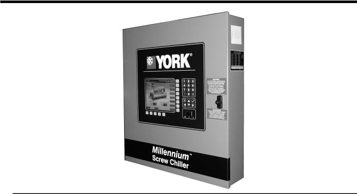
OPTIVIEW CONTROL CENTER
The YORK OptiView Control Center, furnished as standard on each chiller, provides the ultimate in efficiency, monitoring, data recording, chiller protection and operating ease. The control center is a factory mounted, wired, and tested state-of-the-art microprocessor based control system for
R-134a or R-22 screw chillers. The panel is configured with a 10.4 inch diagonal color Liquid Crystal Display
(LCD) surrounded by “soft” keys, which are redefined with one keystroke based on the screen display at that time. This revolutionary development makes chiller operation quicker and easier than ever before. Instead of requiring keystroke after keystroke to hunt for information on a small monochrome LCD screen, a single button reveals a wide array of information on a large, full-color illustration of the appropriate component, which makes information easier to interpret. This is all mounted in the middle of a keypad interface and installed in a locked enclosure.
The LCD display allows graphic animated display of the chiller, chiller sub-systems and system parameters; this allows the presentation of several operating parameters at once. In addition, the operator may view a graphical representation of the historical operation of the chiller as well as the present operation. A Status Bar is displayed at all times on all screens. It contains the System - Status Line and Details Line, the Control Source, Access Level, Date and Time. All date representations and calculations use four digits for the year to provide Year 2000 compliance.
During the Start Sequence and System Lockout Delay, the system status will include a countdown timer indicating the time remaining. The control panel is compatible with the YORK Solid State Starter (optional), Electro-mechanical (E-M) starter, or any customer supplied E-M starter that complies with the YORK R-1051 standard. The locations of various chiller parameters are clearly marked and instructions for specific operations are provided. The panel verbiage is available in other languages as an option, with English always available. Data can be displayed in either English or Metric units, plus keypad entry setpoints of 0.1 increments.
Security access is provided to prevent unauthorized access and/or a change of setpoints. This is accomplished with three different levels of access and passwords for each level. There are screens, displayed values, programmable setpoints and manual controls not shown available to service the chiller. They are only displayed when logged in at the service access level. The Advanced Diagnostics and troubleshooting information for the chiller and the panel is also included.
The panel is fused through a 1-1/2 or 2 KVA transformer in the compressor motor starter to provide individual over-current protected power for all controls. Numbered terminal strips for wiring such as Remote Start/Stop, Flow Switch, Chilled Water Pump and Local or Remote Cycling Device are provided. The Panel also provides field interlocks that indicate the chiller status. These contacts include a Remote Mode Ready To Start, a Cycling
JOHNSON CONTROLS

OptiView Control Center - continued
Shutdown, a Safety Shutdown and a chiller Run Contact. Pressure transducers sense system pressures and thermistors sense system temperatures. The output of each transducer is a DC voltage that is analogous to the pressure input. The output of each thermistor is a DC voltage that is analogous to the temperature it is sensing.
Setpoints can be changed from a remote location via 0-10VDC, 4-20mA, contact closures or through serial communications. The adjustable remote reset range [up to 20°F (11.1°C)] provides flexible, efficient use of remote signal depending on reset needs. Serial data interface to the YORK ISN Building Automation System (BAS) is through the General Protocol Interface Card (GPIC), which can be mounted inside the Control Center.
This printed circuit board requests the required data from the Micro Board and makes it available for the YORK ISN network. This optional board is available through the Johnson Controls BAS group. The operating program is stored in non-volatile memory (EPROM) to eliminate chiller failure due to AC power failure/battery discharge. Programmed setpoints are retained in lithium batterybacked RTC memory for 11 years minimum.
Smart Freeze Point Protection can operate the chiller as low as 36°F (2.22°C) leaving chilled water temperature, without nuisance trips on Low Water Temperature. The sophisticated program and sensor monitors the chiller water temperature to prevent freeze-up. Each programmable point has a pop-up screen with the allowable ranges, so the chiller cannot be programmed to operate outside of its design limits.
Thermal ice storage systems are based on the concept of using off-peak, lower cost electricity to build ice for handling the cooling load during peak hours. The most efficient way to build ice is to maximize chiller load and minimize run time. Standard chiller control systems are not designed for this operating mode. In a typical application, chillers will load and unload to maintain a leaving chilled liquid setpoint. When the YORK YS chiller operates in the thermal storage control mode, the unit will remain at 100% load until the setpoint shutdown temperature is reached.
To add greater operating flexibility and eliminate unnecessary chiller cycling, two different Low Water (Liquid) Temperature Restart Thresholds can be programmed, one for the ice mode and one for the standard cooling mode. This control enhancement is standard on all YS chillers. The chiller can also be left in the standard control mode for temperatures ranging between 20 and 70°F (-6.7 and 21.1°C), for applications involving a process cooling duty that requires leaving chilled liquid temperature setpoint control.
When power is applied to the chiller, the HOME screen is displayed. This screen displays a visual representation of the chiller and a collection of data detailing important operations and parameters. When the chiller is running, the flow of chilled liquid is animated by the alternating shades of color moving in and out of the pipe nozzles. The primary values that need to be monitored and controlled are shown on this screen. They are as follows:
Display Only:
•Chilled Liquid Temperature – Leaving
•Chilled Liquid Temperature – Return
•Condenser Liquid Temperature – Return
•Condenser Liquid Temperature – Leaving
•Motor Run (LED)
•% Full Load Amps
•Operating Hours
With the “soft” keys the operator is only one touch away from the 8 main screens that allow access to the major information and components of the chiller. The 8 screens are the SYSTEM, EVAPORATOR, CONDENSER, COMPRESSOR, OIL SUMP, MOTOR, SETPOINTS, and the
HISTORY. Also on the Home Screen is the ability to LOG IN, LOG OUT and PRINT. Log In and Log Out is the means by which different security levels are accessed.
The SYSTEM screen gives a general overview of common chiller parameters for both shells. This is an end view of the chiller with a 3-D cutaway of both the shells. The following can be viewed from this screen:
Display Only:
• Discharge Temperature
• Chilled Liquid Temperature – Leaving
•Chilled Liquid Temperature – Return
•Chilled Liquid Temperature – Setpoint
•Evaporator Pressure
•Evaporator Saturation Temperature
•Condenser Liquid Temperature – Leaving
•Condenser Liquid Temperature – Return
•Condenser Pressure
•Condenser Saturation Temperature
•Oil Temperature
•Differential Oil Pressure
•% Full Load Amps
•Current Limit
•Slide Valve Position
JOHNSON CONTROLS

FORM 160.80-EG1 (808)
The EVAPORATOR screen displays a cutaway view of the chiller evaporator. All setpoints relating to the evaporator side of the chiller are maintained on this screen. Animation of the evaporation process indicates whether the chiller is presently in RUN condition (bubbling) and liquid flow in the pipes is indicated by alternating shades of color moving in and out of the pipes. Adjustable limits on the low water temperature setpoints allow the chiller to cycle on and off for greater efficiency and less chiller cycling. The chiller cycles off when the leaving chilled water temperature is below setpoint and is adjustable from 1°F (0.55°C) below to a minimum of 36°F (2.22°C).
Restart is adjustable from setpoint up to a max of 80°F (44.4°C). The Panel will check for flow to avoid freezeup of the tubes. If flow is interrupted, shutdown will occur after a minimum of two seconds. The following can also be performed through this screen:
Display Only:
•Chilled Liquid Flow Switch (Open/Closed)
•Chilled Liquid Pump (Run/Stop)
•Evaporator Pressure
•Evaporator Saturation Temperature
•Return Chilled Liquid Temperature
•Leaving Chilled Liquid Temperature
•Evaporator Refrigerant Temperature
•Small Temperature Difference
•Leaving Chilled Liquid Temperature Setpoints – Setpoint
•Leaving Chilled Liquid Temperature Setpoints – Remote Range
•Leaving Chilled Liquid Temperature Setpoints – Shutdown
•Leaving Chilled Liquid Temperature Setpoints – Shutdown Offset
•Leaving Chilled Liquid Temperature Setpoints – Restart
•Leaving Chilled Liquid Temperature Setpoints – Restart Offset
•Ice Storage Active (LED)
Programmable:
•Local Leaving Chilled Liquid Temperature – Range
•Local Leaving Chilled Liquid Temperature – Setpoint
•Leaving Chilled Liquid Temperature Cycling Offset – Shutdown
•Leaving Chilled Liquid Temperature Cycling Offset – Restart
The CONDENSER screen displays a cutaway view of the chiller condenser. The liquid flow is animated to indicate flow through the condenser. All setpoints relating to the condenser side of the chiller are maintained on this screen. With the proper access level this screen also serves as a gateway to controlling the Refrigerant Level. The following can also be viewed through this screen:
Display Only:
•Leaving Condenser Liquid Temperature
•Return Condenser Liquid Temperature
•Condenser Pressure
•Condenser Saturation Temperature
•Small Temperature Difference
•High Pressure Switch (Open/Closed)
•Condenser Liquid Flow Switch
•Condenser Liquid Pump (Run/Stop)
Programmable:
•High Pressure Warning Threshold
•Freeze Warning (Enabled/Disabled)
•Freeze Time
The VARIABLE ORIFICE CONTROL screen, accessed from the CONDENSER screen in SERVICE access level, displays all of the applicable Variable Orifice control parameters and allows a Service Technician to program the Delta P setpoint. The Low Evaporator Pressure and Superheat Override LED’s are located on this screen.
A view of the liquid flow piping to the chiller condenser, along with the solenoid flow control valve, is shown. The following can also be performed through this screen:
Display Only:
•Condenser Pressure
•Evaporator Pressure
•Delta P (Condenser – Evaporator)
•Discharge Temperature
•Condenser Saturation Temperature
•Superheat Temperature
•Low Evaporator Override (LED)
•Superheat Override (LED)
Programmable:
• Delta P Setpoint
JOHNSON CONTROLS |
|

OptiView Control Center - continued
The COMPRESSOR screen displays a cutaway view of the chiller compressor, revealing the rotary screw, and shows all conditions associated with the compressor. The slide valve positioning is animated and with the proper Access level, it can be manually controlled. Animation of the compressor rotors indicates whether the chiller is presently in a run condition. This screen also serves as a gateway to sub-screens for calibrating the slide valve or configuring the optional Hot Gas Bypass. From this screen you can view the following:
Display Only:
•Differential Oil Pressure
•Oil Temperature
•Discharge Temperature
•Discharge Superheat
•Slide Valve Position
•Oil Return Solenoid (LED)
•Full Load Amps (E.M. Starter Only)
•Phase A, B, C Current (SSS Only)
Programmable:
•Slide Valve Load (Manual)
•Slide Valve Hold (Manual)
•Slide Valve Unload (Manual)
•Slide Valve Auto
•Max. Load Temperature
•Minimum Load FLA
•Minimum Load Control Source
The HOT GAS BYPASS screen, accessed from the COMPRESSOR screen, displays a pictorial of the bypass line and solenoid valve location on the chiller. The Hot Gas ON and OFF Setpoints are programmed on this screen and system parameters pertinent to Hot Gas Bypass operation are displayed. An LED illuminates when the Hot Gas solenoid is ON. If the chiller is equipped with the Hot Gas Bypass option, operation must be enabled on the OPERATIONS screen. From this screen you can perform the following:
Display Only:
•Slide Valve Position
•Return Chilled Liquid Temperature
•Leaving Chilled Liquid Temperature
•Hot Gas Solenoid (LED)
Programmable:
•On Setpoint
•Off Setpoint
The SLIDE VALVE CALIBRATION screen displays a cutaway view of the chiller compressor, revealing the rotary screw and slide valve and provides the capability of calibrating the slide valve. From this screen, you can perform the following:
Display Only:
•Slide Valve Loading (LED)
•Slide Valve Unloading (LED)
•Calibration Message
Programmable:
•Start Calibration
•Cancel Calibration
The OIL SEPARATOR screen displays a close-up view of the chiller oil separator/sump and provides all the necessary setpoints for maintaining the Variable Speed Oil Pump (VSOP). This screen also allows manual control of the Frequency Command sent to the VSOP. From this screen you can perform the following:
Display Only:
•Discharge Temperature
•Oil Sump Temperature
•Discharge Superheat
•Oil Pressure
•Filter Pressure
•Seal Pressure
•Differential Oil Pressure
•Differential Filter Pressure
•Differential Seal Pressure
•Offset Pressure
•Oil Return Solenoid (LED)
•Low Separator Oil Level (LED)
1.The MOTOR “soft” key on the HOME screen, when pressed, shows a picture of either a YORK ElectroMechanical Starter or a Solid State Starter, depending on chiller configuration. The Programmable pulldown demand to automatically limit motor loading can be used to minimize building demand charges. Pulldown
JOHNSON CONTROLS

FORM 160.80-EG1 (808)
time period control over four hours, and verification of time remaining in pulldown cycle from display readout. Separate digital setpoint for current limiting between 30 and 100%.
The ELECTRO-MECHANICAL STARTER (E–M) screen displays a picture of the starter and the following values. The ones below are common among both offerings and the values will be displayed on both types of starter screens. From this screen you can perform the following:
Display Only:
•Motor Run (LED)
•Motor Current % Full Load Amps
•Current Limit Setpoints
•Pulldown Demand Time Left
Programmable:
•Local Motor Current Limit
•Pulldown Demand Limit
•Pulldown Demand Time
The SOLID STATE STARTER (SSS) screen displays a picture of the starter and the following values, which are displayed in addition to the common ones listed above. From this screen, you can perform the following:
Display Only:
•Input Power
•kW Hours
•Starter Model
•Voltage – Phase A, B, C
•Current – Phase A, B, C
•Temperature – Phase A, B, C
Programmable:
•Full Load Amps
•Voltage Range
•Starting Current
•Open SCR
•Shorted SCR
•kWH Reset
The SETPOINTS screen provides a convenient location for programming the most common setpoints involved in the chiller control. The Setpoints are shown on other individual screens, but to cut down on needless search-
ing, they can all be found on this screen. This screen also serves as a gateway to a sub-screen for defining the setup of general system parameters. From this screen you can perform the following:
Display Only:
•Leaving Chilled Liquid Temperature – Setpoint
•Leaving Chilled Liquid Temperature Cycling – Shutdown
•Leaving Chilled Liquid Temperature Cycling – Restart
•Current Limit Setpoint
Programmable:
•Local Leaving Chilled Liquid Temperature – Range
•Local Leaving Chilled Liquid Temperature – Setpoint
•Leaving Chilled Liquid Temperature Cycling Offset – Shutdown
•Leaving Chilled Liquid Temperature Cycling Offset – Restart
•Remote Analog Input Range
•Local Motor Current Limit
•Pulldown Demand Limit
•Pulldown Demand Time
The SETUP is the top level of the general configuration parameters. It allows programming of the time and date, along with specifications as to how the time will be displayed. In addition, the chiller configuration as determined by the micro board program jumpers and program switches is displayed. From this screen you can perform the following:
Display Only:
•Chilled Liquid Pump Operation (Displays Standard or
Enhanced)
•Refrigerant Selection (Displays R-22 or R-134a)
•Anti-Recycle (Displays Disabled or Enabled)
•Power Failure Restart (Displays Manual or Automatic)
•Liquid Type (Displays Water or Brine)
Programmable:
•Set Date
•Set Time
•Clock (Enabled/Disabled)
•12/24 Hour
JOHNSON CONTROLS

OptiView Control Center - continued
The following six subscreens can be accessed from the SETUP screen:
The SCHEDULE screen contains more programmable values than a normal display screen. Each programmable value is not linked to a specific button; instead, the select key is used to enable the cursor arrows and check key to program the Start/Stop times for any day of the week up to 6 weeks in advance. The user has the ability to define a standard set of Start/Stop times that are utilized every week or specify exceptions to create a special week.
Programmable:
•Exception Start/Stop Times
•Schedule (Enable/Disable)
•Repeat Sunday Schedule
•Standard Week Start/Stop Times
•Reset All Exception Days
•Select
The USER screen allows definition of the language for the chiller to display and defines the unit of measure.
Programmable:
•System Language
•English/Metric Units
The COMMS screen allows the user to define communications parameters.
Programmable:
•Chiller ID
•COM 2 Baud Rate
•COM 2 Data Bit(s)
•COM 2 Parity Bit(s)
•COM 2 Stop Bit(s)
•Printer Baud Rate
•Printer Data Bit(s)
•Printer Parity Bit(s)
•Printer Stop Bit(s)
The PRINTER screen permits the user to define communications Parameters for the Printer.
Display Only
• Time Remaining Until Next Print
Programmable
• Log Start Time
10
•Output Interval
•Automatic Printer Logging (Enabled/Disabled)
•Print Type
•Print Report
•Print All Histories
The SALES ORDER screen allows definition of the order parameters. Note: This information is loaded at the factory or by the installation service technician.
Display Only
•Model Number
•Panel Serial Number
•Chiller Serial Number
•YORK Order Number
•System Information
•Condenser and Evaporator Design Load Information
•Nameplate Information
The OPERATIONS screen permits definition of parameters pertaining to operation of the chiller. What is defined is whether the control of the chiller will be Local, Digital Remote, Analog Remote, Modem Remote or ISN Remote.
Programmable
• Control Source
The HISTORY screen allows the user to browse through the last ten faults; either safety or cycling shutdowns with the conditions, while the chiller is running or stopped. The faults are color coded for ease in determining the severity at a glance, recording the date, time and description. (See Display Messages for Color Code meanings.)
Display Only
•Last Normal Shutdown
•Last Fault While Running
•Last Ten Faults
Programmable:
•Print History
•Print All Histories
By pressing the VIEW DETAILS key you will move to the HISTORY DETAILS screen. From these screens you are able to see an on-screen printout of all the system parameters at the time of the selected shutdown.
JOHNSON CONTROLS
FORM 160.80-EG1 (808)
Display Only:
• History Printout
Programmable:
•Page Up
•Page Down
•Print History
Also under the HISTORY screen is the TRENDING screen, accessible by the key marked the same. On this screen, up to six operator-selected parameters, selected from a list of over 140, can be plotted in an X/Y graph format. The graph can be customized to record points once every second up to once every hour. There are two types of charts that can be created: single screen, or continuous screen. The single screen collects data for one screen width (450 data points across the X-axis), then stops. The continuous screen keeps collecting the data, but the oldest data drops off the graph from left to right at the next data collection interval. For ease of identification, each plotted parameter, title and associated Y-axis labeling is color coordinated.
Display Only:
•This screen allows the user to view the graphical trending of the selected parameters and is a gateway to the graph setup screens.
Programmable:
•Start
•Stop
•Y-axis
•X-axis
The TREND SETUP screen is used to configure the trending screen. The parameters to be trended are selected from the Trend Common Slots screen, accessed from the Slot Numbers button or the Master Slot Numbers List found in the Operating Manual. The interval at which all the parameters are sampled is selected under the Collection Interval button. The data point minimum and maximum values may be adjusted closer to increase viewing resolution.
Programmable:
•Chart Type (select continuous or one screen)
•Collection Interval
•Select
•Data Point Slot Number (1 - 6)
•Data Point Min (1 - 6)
•Data Point Max (1 - 6)
The TREND COMMON SLOTS screen displays the Master Slot Numbers List of the monitored parameters.
Display Only:
• Slot Numbers
Programmable:
•Page Up
•Page Down
Display Messages
The Control Center continuously monitors the operating system, displaying and recording the cause of any shutdowns (Safety, Cycling or Normal). The condition of the chiller is displayed at the System Status line that contains a message describing the operating state of the chiller; whether it is stopped, running, starting or shutting down. A System Details Line displays Warning, Cycling, Safety, Start Inhibit and other messages that provide further details of the Status Bar messages. Messages are colorcoded: Green – Normal Operations; Yellow – Warnings; Orange – Cycling Shutdowns; and Red – Safety Shutdowns to aid in identifying problems quickly.
Status messages include:
•System Ready To Start
•Cycling Shutdown – Auto Restart
•Safety Shutdown – Manual Restart
•Start Sequence Initiated
•System Run (with countdown timers)
•Start Inhibit
•Slide Valve Closing Before Shutdown
•System Lockout Delay
Run Messages include:
•Leaving Chilled Liquid Control
•Motor Pulldown Limit
•Motor – High Current Limit
Start Inhibit Messages include:
•Anti-Recycle XX min/sec.
•Slide Valve – Position >30%
•Motor Current >15% FLA
•LCSSS – High-Temperature Phase X - Stopped
JOHNSON CONTROLS |
11 |

OptiView Control Center - continued
Warning Messages include:
•Real Time Clock Failure
•Setpoint Override
•Condenser – High Pressure Limit
•Evaporator – Low Pressure Limit
•Freeze Threat From Operating Chiller
•Freeze Threat, Condenser Flow Switch Open
•Low Discharge Superheat Limit
•Low Discharge Superheat Detected
•Maximum Load – Load Limit
•Minimum Load – Load Limit
•Oil – Dirty Filter
•Oil – High Temperature
•Slide Valve Uncalibrated
Routine Shutdown Messages Include:
•Remote Stop
•Local Stop
•Place Compressor Switch In Run Position
Cycling Shutdown Messages Include:
•Multiunit Cycling – Contacts Open
•System Cycling – Contacts Open
•Control Panel – Power Failure
•Leaving Chilled Liquid – Low Temperature
•Leaving Chilled Liquid – Flow Switch Open
•Condenser – Flow Switch Open
•Motor Controller – Contacts Open
•Motor Controller – Loss of Current
•Power Fault
•Control Panel – Schedule
Solid State Starter Only (LCSSS)
•Initialization Failed
•Serial Communications
•Requesting Fault Data
•Stop Contacts Open
•Power Fault
•Low Phase (X) Temperature Sensor
•Run Signal
•Invalid Current Scale Selection
•Phase Locked Loop
•Low Supply Line Voltage
•High Supply Line Voltage
•Logic Board Processor
•Logic Board Power Supply
•Phase Loss
Safety Shutdown Messages include:
•Evaporator – Low Pressure
•Evaporator – Low Pressure – Smart Freeze
•Evaporator – Transducer or Leaving Liquid Probe
•Evaporator – Transducer or Temperature Sensor
•Condenser – High Pressure Contacts Open
•Condenser – High Pressure
•Condenser – Pressure Transducer Out of Range
•Auxiliary Safety – Contacts Closed
•Discharge – High Temperature
•Discharge – Low Temperature
•Oil – High Temperature
•Oil – Low Differential Pressure
•Oil – Low Differential Seal Pressure
•Oil or Condenser Transducer Error
•Oil – Clogged Filter
•Oil – High Pressure
•Oil – Separator – Low Level
•Control Panel – Power Failure
•Watchdog – Software Reboot
Solid State Starter Only (LCSSS)
•Shutdown – Requesting Fault Data . . .
•High Instantaneous Current
•High Phase (X) Heatsink Temperature – Running
•105% Motor Current Overload
•Motor or Starter – Current Imbalance
•Open SCR
•Phase Rotation
12 |
JOHNSON CONTROLS |

Mechanical Specifications
FORM 160.80-EG1 (808)
standard unit General
The YORK Millennium YS Rotary Screw Chiller is completely factory-packaged, including evaporator, condenser, sub-cooler, oil separator, compressor, motor, lubrication system, control center and refrigerant isolation valves. The factory package consists of a “leak tight” design. All units ship as standard with a full charge of refrigerant and oil. Units can also be shipped in sections (optional) to accommodate job site requirements.
The services of a Johnson Controls factory-trained, field service representative are incurred to supervise or perform the final leak testing, charging, the initial start-up, and concurrent operator instructions.
Compressor
The Frick Rotary Twin Screw Compressor is engineered and constructed to meet the exact requirements of the industrial refrigeration market. It utilizes state-of-the-art technology to provide the most reliable and energy-ef- ficient compressor available at all operating conditions.
The compressor operates at 3750 RPM for 60 Hertz and 2975 RPM for 50 Hertz. The compressor housing is made of cast iron, precision-machined to provide minimal clearance for the rotors. Compressor housing has a design working pressure (DWP) of 300 PSIG (2068 kPa) minimum, and hydro-tested at 544 PSIG (3751 kPa).
The rotors are manufactured from forged steel and use asymmetric profiles. The compressor incorporates a complete anti-friction bearing design for reduced power and increased reliability. Four separate cylindrical roller bearings handle radial loads. Two 4-point angular contact ball bearings handle axial loads. Together, they maintain accurate rotor positioning at all pressure ratios, thereby minimizing blow-by and maintaining efficiency.
A check valve is installed in the compressor discharge housing (suction housing for S4 and S5 compressor) to prevent compressor rotor back spin because of system refrigerant pressure gradients during shutdown.
The open-drive compressor shaft seal consists of precision ceramic seal faces, metallic bellows, rotating member,
PTFE ‘C’-Ring static seal, and multi-port oil injection ring.
The seal cavity is maintained at intermediate pressure with its oil discharged to the oil drain from the compressor.
Combining intermediate pressure with direct oil injection provides cool, non-foaming lubricant to the seal assuring a longer lifespan.
Capacity Control
Capacity control is achieved by use of a slide valve which JOHNSON CONTROLS
provides fully modulating capacity control from 100% to 10% of full load. The slide valve is actuated by oil pressure, controlled by external solenoid valves via the OptiView Control Center.
Oil Separator
The oil separator is a horizontal design without moving parts. Effective oil separation is achieved by gravity dropout of oil from the refrigerant gas as velocity decreases upon entering the separator, and by mesh pads to provide final gas/oil separation before gas enters the condenser.
The oil separator is designed for 345 PSIG (2378 kPa) design working pressure, tested at 517 PSIG (3565 kPa), and stamped in accordance with ASME Boiler and Pressure Vessel Code, Section VIII - Division 1.
Each vessel has a refrigerant relief device(s) set at 300 PSIG (2068 kPa). In addition to the spring-loaded, re-seat- ing-type relief valves sized for pressure vessel volume, each unit is equipped with a rupture disk. This rupture disk is able to relieve the entire pumping capacity of the compressor if electronic safeties fail, providing protection for property and personnel. This device is set for 345 PSIG (2378 kPa). Alternatively, the shell side may be designed to European Pressure Vessel Codes and stamped in accordance with A.D. Merkblatter or other European Pressure Vessel design code. When required by the refrigeration safety code, each vessel has a dual refrigerant relief device(s).
Lubrication
The main unit oil reservoir is located in the oil separator. The compressor also has an oil reservoir located at the rotor bearings to provide lubrication during start-up, coat down, and in the event of a power failure. During operation, system pressure differential provides proper oil flow without the need of an auxiliary oil pump. This minimizes energy consumption.
The chiller is shipped with a 3 Micron absolute oil filter, ensuring a clean oil system and superior compressor life.An external, replaceable cartridge oil filter is supplied with manual isolation stop valves for ease of servicing.
An optional dual oil filter housing with isolation valves is available on all units. This allows immediate switching from one filter to the other, eliminating downtime during filter changes. The off-line oil filter can be changed during chiller operation.
A 500 watt (115 volt - 1-phase - 60/50Hz) immersion oil heater is located in the oil separator reservoir, temperature actuated to efficiently remove refrigerant from the oil. Oil heater power supply is factory wired from the control panel. A factory-piped refrigerant-cooled oil
13

Mechanical Specifications - continued
cooler is provided as standard. No auxiliary water piping is required. An oil eductor automatically removes oil which may have migrated to the evaporator and returns it to the compressor.
motor driveline
The compressor motor is an open drip-proof, squirrel cage, induction type constructed to Johnson Controls design specifications. 60 Hertz motors operate at 3750
RPM; 50 Hertz motors operate at 2975 RPM. The open motor is provided with a D-Flange and is factory-mounted to a cast-iron adaptor mounted on the compressor. This unique design allows the motor to be rigidly coupled to the compressor to provide factory alignment of motor and compressor shafts.
Motor drive shaft is directly connected to the compressor shaft with a flexible disc coupling. Coupling has all metal construction with no wearing parts to assure long life. Additionally, no lubrication is required – providing low maintenance.
For units utilizing remote electro-mechanical starters, a large steel terminal box with gasketed front access cover is provided for field connected conduit. There are six terminals (three for medium voltage) brought through the motor casing into the terminal box. Jumpers are furnished for three-lead type of starting. Motor terminal lugs are not furnished. Overload/overcurrent transformers are furnished with all units. For units furnished with factorypackaged Solid State Starters, refer to the Accessories and Modifications section (page 17).
Heat Exchangers
Shells
Evaporator and condenser shells are fabricated from rolled carbon steel plates with fusion welded seams. Carbon steel tube sheets, drilled and reamed to accommodate the tubes, are welded to the end of each shell. Intermediate tube supports are fabricated from carbon steel plates, drilled and reamed to eliminate sharp edges, and spaced no more than four feet apart. The refrigerant side of each shell is designed, tested, and stamped in accordance with ASME Boiler and Pressure Vessel Code, Section VIII – Division I, or other pressure vessel code as appropriate.
Tubes
Heat exchanger tubes are state-of-the-art, high efficiency, externally and internally enhanced type to provide optimum performance. Tubes in both the evaporator and condenser are 3/4” O.D. copper alloy and utilize the
“skip-fin” design, providing a smooth internal and external surface at each intermediate tube support. This provides
14
extra wall thickness (up to twice as thick) and non-work hardened copper at the support location, extending the life of the heat exchangers. Each tube is roller expanded into the tube sheets providing a leak-proof seal, and is individually replaceable.
Evaporator
The evaporator is a shell and tube, flooded type heat exchanger. A distributor trough provides uniform distribution of refrigerant over the entire shell length to yield optimum heat transfer. A suction baffle or aluminum mesh eliminators are located above the tube bundle to prevent liquid refrigerant carryover into the compressor. A 1 1/2” liquid level sight glass is conveniently located on the side of the shell to aid in determining proper refrigerant charge. The evaporator shell contains a dual refrigerant relief valve arrangement set at 180 PSIG (1241 kPa); or single-relief valve arrangement, if the chiller is supplied with the optional refrigerant isolation valves. A 1” refrigerant charging valve is provided.
Condenser
The condenser is a shell and tube type, with a discharge gas baffle to prevent direct high velocity impingement on the tubes. The baffle is also used to distribute the refrig erant gas flow properly for most efficient heat transfer.
An integral sub cooler is located at the bottom of the condenser shell providing highly effective liquid refriger ant subcooling to provide the highest cycle efficiency. The condenser contains dual refrigerant relief valves set at 235 PSIG (1620 kPa).
Water Boxes
The removable water boxes are fabricated of steel. The design working pressure is 150 PSIG (1034 kPa) and the boxes are tested at 225 PSIG (1551 kPa). Integral steel water baffles are located and welded within the water box to provide the required pass arrangements. Stub out water nozzle connections with ANSI/AWWA C-606 grooves are welded to the water boxes. These nozzle connections are suitable for ANSI/AWWA C-606 couplings welding or flanges, and are capped for shipment. Plugged 3/4” drain and vent connections are provided in each water box.
refrigerant flow control
The YS Chiller is equipped with a refrigerant metering device consisting of a fixed orifice and bypass solenoid valve, which automatically adjusts to all real-world operating conditions.This control ensures proper refrigerant flow to the evaporator over a wide range of operating conditions, including thermal storage applications and chilled water reset. Valve operation is programmable and can be customized for a specific application via the control panel keyboard.
JOHNSON CONTROLS

FORM 160.80-EG1 (808)
refrigerant isolation
The condenser shell serves as a refrigerant receiver to store the system charge during servicing. Manually operated isolation valves are located at the inlet and outlet of the condenser. Valves are also provided to facilitate removal of the refrigerant from the system when necessary.
Optiview control center General
The chiller is controlled by a stand-alone microprocessorbased control center. The chiller control panel provides control of chiller operation and monitoring of chiller sensors, actuators, relays and switches.
Control Panel
The control panel includes a 10.4 inch diagonal color liquid crystal display (LCD) surrounded by “soft” keys, which are redefined based on the screen displayed at that time, mounted in the middle of a keypad interface and installed in a locked enclosure. The screen details all operations and parameters, using a graphical representation of the chiller and its major components. Panel verbiage is available in other languages as an option with English always available. Data can be displayed in either English or Metric units. Smart Freeze Point Protection will run the chiller at 36°F (2.22°C) leaving chilled water temperature and not experience nuisance trips on low water temperature. The sophisticated program and sensor monitors the chiller water temperature to prevent freeze-up. When needed, Hot Gas Bypass is available as an option. The panel displays countdown timer messages so the operator knows when functions are starting and stopping. Every programmable point has a pop-up screen with the ranges included, so the chiller can not be programmed to operate outside of its design limits.
The control panel includes a thermal ice storage control mode which enhances system performance during ice building operation when compared to standard cooling logic. In thermal storage control mode, the chiller will operate at 100% load until the setpoint shutdown temperature is reached. To add greater operating flexibility and eliminate unnecessary chiller cycling, two different Low Water (Liquid) Temperature Restart Thresholds are programmable, one for the ice mode and one for the standard cooling mode. The chiller has the capability to remain in the standard control mode for temperatures between 20°F to 70°F (–6.7°C to 21.1°C) for applications involving a process cooling duty that requires leaving chilled liquid temperature setpoint control.
The chiller control panel also provides:
JOHNSON CONTROLS
1.System operating information including:
•Return and Leaving Chilled Water Temperature
•Return and Leaving Condenser Water Tem perature
•Evaporator and Condenser Saturation Tem perature
•Oil Pressure at Compressor and Oil Filter Differential
•Percent Motor Current
•Evaporator and Condenser Saturation Tem perature
•Compressor Discharge Temperature
•Oil Temperature
•Percent Slide Valve Position
•Operating Hours
•Number of Unit Starts
2.Digital Programming of Setpoints Through The Universal Keypad Including:
•Leaving Chilled Water Temperature
•Percent Current Limit
•Pull-Down Demand Limiting
•Six-Week Schedule For Starting and Stopping The Chiller, Pumps and Tower
•Remote Reset Temperature Range
3.Status Messages Indicating:
•System Ready To Start
•System Running
•System Coastdown
•System Safety Shutdown – Manual Restart
•System Cycling Shutdown – Auto Restart
•System Prelube
•Start Inhibit
4.The text displayed within the system status and system details field is displayed as a color-coded message to indicate severity: red for safety fault; orange for cycling faults; yellow for warnings; and green for normal messages.
5.Safety shutdowns are enunciated through the display and the status bar, and consist of system status, system details, day, time, cause of shutdown, and type of restart required. Safety shutdowns with a fixed speed drive include:
•Evaporator – Low Pressure
•Evaporator – Low Pressure - Smart Freeze
•Evaporator – Transducer or Leaving Liquid Probe
15

Mechanical Specifications - continued
•Evaporator – Transducer or Temperature Sensor
•Condenser – High Pressure Contacts Open
•Condenser – High Pressure
•Condenser – Pressure Transducer Out Of Range
•Auxiliary Safety – Contacts Closed
•Discharge – High Temperature
•Discharge – Low Temperature
•Oil – High Temperature
•Oil – Low Differential Pressure
•Oil – Low Differential Seal Pressure
•Oil Or Condenser Transducer Error
•Oil – Clogged Filter
•Oil – High Pressure
•Oil – Separator – Low Level
•Control Panel – Power Failure
•Watchdog – Software Reboot
5.1Safety shutdowns with a Solid State Starter (LCSSS) include:
•Shutdown Requesting Fault Data...
•High Instantaneous Current
•High Phase (X) Heatsink Temperature Run ning
•105% Motor Current Overload
•Motor Or Starter – Current Imbalance
•Phase (X) Shorted SCR
•Open SCR
•Phase Rotation
6.Cycling shutdowns enunciated through the display and the status bar, and consists of system status, system details, day, time, cause of shutdown, and type of restart required.
Cycling shutdowns with a fixed speed drive include:
•Multiunit Cycling Contacts Open
•System Cycling Contacts Open
•Control Panel Power Failure
•Leaving Chilled Liquid – Low Temperature
•Leaving Chilled Liquid – Flow Switch Open
•Condenser Flow Switch Open
•Motor Controller – Contacts Open
•Motor Controller – Loss Of Current
•Power Fault
16
•Control Panel – Schedule
6.1Cycling shutdowns with a Solid State Starter (LCSSS) include:
•Initialization Failed
•Serial Communications
•Requesting Fault Data
•Stop Contacts Open
•Power Fault
•Low Phase (X) Temperature Sensor
•Run Signal
•Invalid Current Scale Selection
•Phase Locked Loop
•Low Supply Line Voltage
•High Supply Line Voltage
•Logic Board Processor
•Logic Board Power Supply
•Phase Loss
7.Security access to prevent unauthorized change of setpoints, to permit local or remote control of the chiller, and to allow manual operation of the prerotation vanes and oil pump. Access is through ID and password recognition, which is defined by three different levels of user competence: view, operator, and service.
8.Trending data with the ability to customize points of once every second to once every hour. The panel will trend up to 6 different parameters from a list of over 140, without the need of an external monitoring system.
9.The operating program is stored in non volatile memory (EPROM) to eliminate reprogramming the chiller due to AC power failure or battery discharge. Programmed setpoints are retained in lithium battery backed RTC memory for a minimum of 11 years with power removed from the system.
10. A fused connection through a transformer in the compressor motor starter to provide individual over current protected power for all controls.
11. A numbered terminal strip for all required field interlock wiring.
12. An RS 232 port to output all system operating data, shutdown/cycling message, and a record of the last
10 cycling or safety shutdowns to a field supplied printer. Data logs to a printer at a set programmable interval. This data can be pre-prograrnmed to print from 1 minute to 1 day.
13. The capability to interface with a building automation
JOHNSON CONTROLS

FORM 160.80-EG1 (808)
system to provide:
•remote chiller start and stop
•remote leaving chilled liquid temperature adjust
•remote current limit setpoint adjust
•remote ready to start contacts
•safety shutdown contacts
•cycling shutdown contacts
•run contacts
Codes and Standards
•ASME Boiler and Pressure Vessel Code – Section Vlll Division 1.
•ARI Standard 550/590
•c/U.L. – Underwriters Laboratory
•ASHRAE 15 – Safety Code for Mechanical Refrigeration
•ASHRAE Guideline 3 – Reducing Emission of Halogenated Refrigerants in Refrigeration and Air-Condition- ing Equipment and Systems
•NEC – National Electrical Code
•OSHA – Occupational Safety and Health Act
•A.D. Merkblatter
Isolation Mounting
The unit is provided with four vibration isolation mounts consisting of 1” (25.4 mm) thick neoprene isolation pads for field mounting under the steel mounting pads located on the tube sheets.
Refrigerant Containment
The standard unit has been designed as a complete and compact factory packaged chiller. As such, it has mini mum joints from which refrigerant can leak. The entire assembly has been thoroughly leak tested at the factory prior to shipment. The YORK chiller includes service valves conveniently located to facilitate transfer of refrig erant to a remote refrigerant storage/recycling system. Optional condenser isolation valves permit storage of the charge in the condenser.
Paint
Exterior surfaces are protected with one coat of Carib bean blue, durable alkyd modified, vinyl enamel, ma chinery paint.
JOHNSON CONTROLS |
17 |
Loading...