


TOSHIBA Thermal Printer
B-EX4 SERIES
 Maintenance Manual
Document No. EO18-33027
Original Mar, 2011 (Revised )
(PRELIMINARY VERSION)
PRINTED IN JAPAN
EO18-33027
|
|
|
TABLE OF CONTENTS |
|
|
|
Page |
1. |
UNPACKING-------------------------------------------------------------------------------------------------------- |
1- 1 |
|
|
1.1 |
PROCEDURES --------------------------------------------------------------------------------------------------- |
1- 1 |
|
1.2 |
CHECKS ------------------------------------------------------------------------------------------------------------ |
1- 3 |
2. |
PRINTER INSTALLATION-------------------------------------------------------------------------------------- |
1- 3 |
|
3.NOTE FOR OPTIONAL EQUIPMENT INSTALLATION
/MAJOR UNIT REPLACEMENT/MAINTENANCE---------------------------------------------------- |
3- 1 |
|
3.1 |
OPENING/CLOSING THE TOP COVER------------------------------------------------------------------- |
3- 3 |
3.2 |
REMOVING THE SIDE PANEL (L) -------------------------------------------------------------------------- |
3- 3 |
3.3 |
OPENING/CLOSING THE PRINTER BLOCK ------------------------------------------------------------ |
3- 3 |
3.4 |
REMOVING THE OPERATION PANEL -------------------------------------------------------------------- |
3- 5 |
4. INSTALLATION PROCEDURE FOR OPTIONAL EQUIPMENT |
-------------------------------------4- 1 |
|
4.1 |
DISK CUTTER (B-EX204-QM-R)----------------------------------------------------------------------------- |
4- 2 |
4.2 |
ROTARY CUTTER (B-EX204-R-QM-R)-------------------------------------------------------------------- |
4- 4 |
4.3 |
PEEL OFF MODULE (B-EX904-H-QM-R) ---------------------------------------------------------------- |
4-12 |
4.4 |
RIBBON SAVING MODULE (B-EX904-R-QM-R) ------------------------------------------------------- |
4-20 |
4.5 |
RTC/USB INTERFACE BOARD (B-EX700-RTC-QM-R)---------------------------------------------- |
4-23 |
4.6 |
EXPANSION I/O INTERFACE BOARD (B-EX700-IO-QM-R) --------------------------------------- |
4-25 |
4.7 |
WIRELESS LAN BOARD (B-EX700-WLAN-QM-R) ---------------------------------------------------- |
4-28 |
4.8 |
PARALLEL INTERFACE BOARD (B-EX700-CEN-QM-R) ------------------------------------------- |
4-31 |
TBD: |
|
|
B-EX700-RS-QM-R Serial I/F card
B-EX700-RFID-QM-R HF RFID module mount kit
B-EX700-RFID-EU-QM-R UHF RFID kit for EU
B-EX700-RFID-U2-QM-R UHF RFID kit for US
B-EX700-RFID-U2-CN-R UHF RFID kit for CN
EO18-33027
5. SYSTEM MODE---------------------------------------------------------------------------------------------------- |
5- 1 |
|
5.1 |
OPERATION PANEL -------------------------------------------------------------------------------------------- |
5- 1 |
5.2 |
OVERVIEW -------------------------------------------------------------------------------------------------------- |
5- 2 |
5.3 |
SELF-DIAGNOSTIC TEST------------------------------------------------------------------------------------- |
5- 3 |
|
5.3.1 Counter, Parameter / MAINTENACE COUNT ------------------------------------------------------ |
5- 3 |
|
5.3.2 Auto Diagnostic / AUTO DIAGNOTICS ------------------------------------------------------------- |
5-16 |
|
5.3.3 Print Head Element Check ------------------------------------------------------------------------------ |
5-23 |
5.4 |
PARAMETER SETTING --------------------------------------------------------------------------------------- |
5-24 |
|
5.4.1 Printer setting / PRINTER SET ------------------------------------------------------------------------ |
5-24 |
|
5.4.1.1 Media loading / MEDIA LOAD------------------------------------------------------------------- |
5-24 |
|
5.4.1.2 Setting for forward feed standby / FORWARD WAIT -------------------------------------- |
5-25 |
|
5.4.1.3 Forward feed standby position / FORWARD WAIT POS. ------------------------------- |
5-25 |
|
5.4.1.4 Standby action / FW/BK ACT. ------------------------------------------------------------------ |
5-25 |
|
5.4.1.5 HU CUT/RWD --------------------------------------------------------------------------------------- |
5-25 |
|
5.4.1.6 Ribbon save / RBN SAVE ------------------------------------------------------------------------ |
5-25 |
|
5.4.1.7 Pre peel-off / PRE PEEL OFF ------------------------------------------------------------------- |
5-26 |
|
5.4.1.8 Back feed / BACK SPEED ----------------------------------------------------------------------- |
5-26 |
|
5.4.2 Soft control setting / SOFTWARE SET------------------------------------------------------------------ |
5-27 |
|
5.4.2.1 Character code / FONT CODE------------------------------------------------------------------ |
5-28 |
|
5.4.2.2 Font “0” type / ZERO FONT---------------------------------------------------------------------- |
5-28 |
|
5.4.2.3 Control code / CODE ------------------------------------------------------------------------------ |
5-28 |
|
5.4.2.4 Manual selection / MANUAL --------------------------------------------------------------------- |
5-29 |
|
5.4.2.5 Peel-off wait status / PEEL OFF STATUS---------------------------------------------------- |
5-29 |
|
5.4.2.6 USB STATUS / USB I/F STATUS -------------------------------------------------------------- |
5-29 |
|
5.4.2.7 FEED Key Function -------------------------------------------------------------------------------- |
5-29 |
|
5.4.2.8 Kanji special code / KANJI CODE -------------------------------------------------------------- |
5-30 |
|
5.4.2.9 Euro code / EURO CODE ------------------------------------------------------------------------ |
5-30 |
|
5.4.2.10 Auto head broken check / AUTO HD CHK ------------------------------------------------- |
5-30 |
|
5.4.2.11 WEB Printer / WEB PRINTER ----------------------------------------------------------------- |
5-30 |
|
5.4.2.12 Ribbon near end / RBN NEAR END---------------------------------------------------------- |
5-31 |
|
5.4.2.13 External I/O mode / EX.I/O --------------------------------------------------------------------- |
5-31 |
|
5.4.2.14 Paper / ribbon end / LBL/RBN END ---------------------------------------------------------- |
5-31 |
|
5.4.2.15 MaxiCode specification / MAXI CODE------------------------------------------------------- |
5-32 |
|
5.4.2.16 XML -------------------------------------------------------------------------------------------------- |
5-32 |
|
5.4.2.17 Threshold selection / THRESHOLD SELECT---------------------------------------------- |
5-33 |
|
5.4.2.18 Print method / ENERGY TYPE ---------------------------------------------------------------- |
5-33 |
|
5.4.2.19 Power save time / PW SAVE TIME----------------------------------------------------------- |
5-33 |
|
5.4.3 LCD DISPLAY SETTING / PANEL----------------------------------------------------------------------- |
5-34 |
|
5.4.3.1 Language of LCD display / LCD LANGUAGE ----------------------------------------------- |
5-34 |
|
5.4.3.2 Machine name / MACHINE NAME ------------------------------------------------------------- |
5-34 |
|
5.4.3.3 Print page / PRINT PAGE ------------------------------------------------------------------------ |
5-34 |
|
5.4.3.4 IP address / IP ADDRESS ----------------------------------------------------------------------- |
5-34 |
|
5.4.3.5 Contrast adjustment / CONTRAST------------------------------------------------------------- |
5-35 |
|
5.4.4 Password setting / PASSWORD-------------------------------------------------------------------------- |
5-35 |
|
5.4.4.1 Boot display of system mode and user mode when password is enabled------------ |
5-36 |
EO18-33027
5.5 Fine adjustment value setting/ ADJUST SET ------------------------------------------------------------ |
5-37 |
|
5.5.1 |
Feed / FEED ADJ.----------------------------------------------------------------------------------------- |
5-38 |
5.5.2 |
Cut position / CUT ADJ ---------------------------------------------------------------------------------- |
5-38 |
5.5.3 |
Back feed / BACK ADJ----------------------------------------------------------------------------------- |
5-43 |
5.5.4 |
X direction position / X ADJUST ----------------------------------------------------------------------- |
5-44 |
5.5.5 |
Density fine tune (Thermal transfer) / TONE ADJ.(TRANS.) ---------------------------------- |
5-44 |
5.5.6 |
Density fine tune (Direct thermal transfer) / TONE ADJ.(DIRECT) --------------------------- |
5-44 |
5.5.7 |
Ribbon (Rewinder) / RBN ADJ.<FW> ---------------------------------------------------------------- |
5-45 |
5.5.8 |
Ribbon (Feeder) / RBN ADJ.<BK>-------------------------------------------------------------------- |
5-45 |
5.5.9 |
Refrective sensor fine tune / THRESHOLD <REFL.> ------------------------------------------- |
5-46 |
5.5.10 |
Transmissive sensor fine tune / THRESHOLD <TRANS.> ------------------------------------- |
5-46 |
5.6 TEST PRINT ------------------------------------------------------------------------------------------------------ |
5-48 |
5.6.1 Print condition setting / PRINT CONDITION-------------------------------------------------------- |
5-48 |
5.6.2 1-dot slant line print / SLANT LINE(1DOT) --------------------------------------------------------- |
5-51 |
5.6.3 3-dot slant line print / SLANT LINE(3DOT) --------------------------------------------------------- |
5-51 |
5.6.4 Character print / CHARACTERS ---------------------------------------------------------------------- |
5-52 |
5.6.5 Barcode print / BARCODE ------------------------------------------------------------------------------ |
5-52 |
5.6.6 White line print / NON-PRINTING --------------------------------------------------------------------- |
5-53 |
5.6.7 Factory test / FACTORY TEST ------------------------------------------------------------------------ |
5-53 |
5.6.8 Auto print (Transmissive) / AUTO PRINT (TRANS.) --------------------------------------------- |
5-53 |
5.6.9 Auto print (Reflective) / AUTO PRINT (REFL.) ---------------------------------------------------- |
5-54 |
5.7 |
SENSOR ADJUSTMENT-------------------------------------------------------------------------------------- |
5-55 |
|
|
5.7.1 |
Temperature sensor/ TEMPERATURE -------------------------------------------------------------- |
5-55 |
|
5.7.2 |
Reflective sensor / REFLECT -------------------------------------------------------------------------- |
5-55 |
|
5.7.3 |
Transmissive / TRANS. --------------------------------------------------------------------------------- |
5-56 |
|
5.7.4 |
Paper empty level / PE REFL./TRANS. ------------------------------------------------------------- |
5-56 |
|
5.7.5 |
Ribbon end / RIBBON ------------------------------------------------------------------------------------ |
5-56 |
5.8 |
RAM CLEAR ------------------------------------------------------------------------------------------------------ |
5-57 |
|
|
5.8.1 |
No RAM clear / NO RAM CLEAR ------------------------------------------------------------------- |
5-57 |
|
5.8.2 |
Counter clear / MAINTE.CNT CLEAR-------------------------------------------------------------- |
5-57 |
|
5.8.3 |
Parameter clear / PARAMETER CLEAR ---------------------------------------------------------- |
5-58 |
5.9 |
IP ADDRESS SETTING --------------------------------------------------------------------------------------- |
5-64 |
|
|
5.9.1 |
Network / NETWORK ------------------------------------------------------------------------------------ |
5-64 |
|
5.9.2 |
USB ----------------------------------------------------------------------------------------------------------- |
5-69 |
|
5.9.3 |
RS-232C----------------------------------------------------------------------------------------------------- |
5-70 |
|
5.9.4 |
Centronics / CENTRO. ---------------------------------------------------------------------------------- |
5-71 |
5.10 |
BASIC SETTING------------------------------------------------------------------------------------------------- |
5-72 |
|
|
5.10.1 |
Basic function / BASIC ----------------------------------------------------------------------------------- |
5-72 |
|
5.10.2 |
File display / FILE MAINTENANCE------------------------------------------------------------------- |
5-72 |
|
5.10.3 |
Trace function / TRACE---------------------------------------------------------------------------------- |
5-72 |
|
5.10.4 |
Extended mode / EXPAND MODE-------------------------------------------------------------------- |
5-72 |
5.11 |
RFID Module Setting-------------------------------------------------------------------------------------------- |
5-73 |
|
|
5.11.1 |
Test / TEST ------------------------------------------------------------------------------------------------- |
5-74 |
|
5.11.2 |
Module / MODULE ---------------------------------------------------------------------------------------- |
5-75 |
|
5.11.3 |
Retry / RETRY --------------------------------------------------------------------------------------------- |
5-77 |
|
5.11.4 |
UHF setting / UHF SETTING --------------------------------------------------------------------------- |
5-79 |
|
5.11.5 |
Other / OTHER--------------------------------------------------------------------------------------------- |
5-83 |
EO18-33027
6. |
ON LINE MODE----------------------------------------------------------------------------------------------------- |
6-1 |
|
|
6.1 |
THRESHOLD SETTING-------------------------------------------------------------------------------------------- |
6-8 |
|
6.2 |
ONLINE MODE LCD DISPLAY--------------------------------------------------------------------------------- |
6-11 |
|
6.3 |
HELP DISPLAY ----------------------------------------------------------------------------------------------------- |
6-14 |
7. |
PERIODIC MAINTENANCE PROCEDURE ---------------------------------------------------------------- |
7- 1 |
|
8 |
TROUBLESHOOTING -------------------------------------------------------------------------------------------- |
8 1 |
|
9.(TBD)
10. MAJOR UNIT REPLACEMENT (T.B.D)---------------------------------------------------------------------- |
10- |
||
10.1 |
POWER SUPPLY UNIT----------------------------------------------------------------------------------------- |
10- |
|
10.2 |
MAIN PC BOARD ------------------------------------------------------------------------------------------------ |
10- |
|
10.3 |
PANEL PC BOARD AND LCD UNIT ------------------------------------------------------------------------ |
10- |
|
|
10.3.1 |
LCD ------------------------------------------------------------------------------------------------------------- |
10- |
|
10.3.2 |
Panel PC Board---------------------------------------------------------------------------------------------- |
10- |
10.4 |
STEPPING MOTOR --------------------------------------------------------------------------------------------- |
10- |
|
10.5 |
RIBBON MOTORS (TAKE-UP, FEED) --------------------------------------------------------------------- |
10- |
|
|
10.5.1 Ribbon Motor (Take-up) ------------------------------------------------------------------------- |
10- |
|
|
10.5.2 Ribbon Motor (Feed)------------------------------------------------------------------------------ |
10- |
|
10.6 |
RIBBON MOTOR SENSORS (TAKE-UP, FEED)-------------------------------------------------------- |
10- |
|
|
10.6.1 Ribbon Motor Sensor (Take-up) ------------------------------------------------------------------------- |
10- |
|
|
10.6.2 Ribbon Motor Sensor (Feed) ----------------------------------------------------------------------------- |
10- |
|
10.7 |
PRINT HEAD ------------------------------------------------------------------------------------------------------ |
10- |
|
10.8 |
PLATEN------------------------------------------------------------------------------------------------------------- |
10- |
|
10.9 |
FEED ROLLER---------------------------------------------------------------------------------------------------- |
10- |
|
10.10 PINCH ROLLER ASS’Y----------------------------------------------------------------------------------------- |
10- |
||
10.11 MEDIA SENSORS (UPPER, LOWER) --------------------------------------------------------------------- |
10- |
||
|
10.11.1 Removing the Media Sensor Ass’y---------------------------------------------------------------------- |
10- |
|
|
10.11.2 Replacing the Media Sensor (Upper)------------------------------------------------------------------- |
10- |
|
|
10.11.3 Replacing the Media Sensor (Lower)------------------------------------------------------------------- |
10- |
|
|
10.11.4 Reassembling the Media Sensor Ass’y ---------------------------------------------------------------- |
10- |
|
10.12 HEAD UP SENSOR---------------------------------------------------------------------------------------------- |
10- |
||
10.13 PRINTER OPEN SENSOR ------------------------------------------------------------------------------------ |
10- |
||
10.14 RIBBON END SENSOR ---------------------------------------------------------------------------------------- |
10- |
||
10.15 FAN MOTOR------------------------------------------------------------------------------------------------------- |
10- |
||
11. RFID ANALYZE TOOL------------------------------------------------------------------------------------------ |
11-1 |
|
11.1 |
System Requirement ------------------------------------------------------------------------------------------- |
11-1 |
11.2 |
Set up--------------------------------------------------------------------------------------------------------------- |
11-2 |
11.3 |
Application Functions ------------------------------------------------------------------------------------------ |
11- 3 |
11.4 |
Operating Procedure------------------------------------------------------------------------------------------ |
11-13 |

EO18-33027
CAUTION!
1.This manual may not be copied in whole or in part without prior written permission of TOSHIBA TEC.
2.The contents of this manual may be changed without notification.
Copyright © 2011
by TOSHIBA TEC CORPORATION All Rights Reserved
570 Ohito, Izunokuni-shi, Shizuoka-ken, JAPAN
1. UNPACKING
1. UNPACKING
EO18-33027
1.1 PROCEDURE
1.1 PROCEDURE
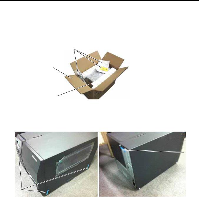
1)Open the carton.
2)Unpack the accessories and the front pad from the carton.
Accessories
Carton
Front Pad
3)Unpack the pads and the printer from the carton.
4)Remove the four pieces of tape and the rear pad from the printer.
Tape
Tape
1- 1
1. UNPACKING
EO18-33027
1.1 PROCEDURE
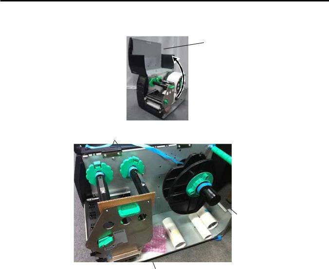
5)Open the top cover and remove the five pieces of tape. And then, open the ribbon shaft holder plate to remove the ribbon shaft pad from the printer.
 Top Cover
Tape
Ribbon Shaft Pad
Tape
Ribbon Shaft Holder Plate
1- 2
1. UNPACKING
EO18-33027
1.2 CHECKS
1.2 CHECKS
1)Check for damage or scratches on the printer.
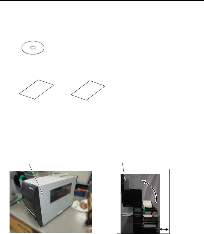
2)Confirm that none of the accessories are missing. The parts below are provided as accessories.
CD-ROM (1 pc.) <Contents>
•Bar code printer application (BarTender Ultra Lite)
•Windows Driver
•Owner's Manual
•Specifications (Programming, Key operation, etc.)
•Product information (Catalogue)
Carton |
|
Safety precautions |
Quick installation manual |
NOTES: Keep the carton and pads for later transport.
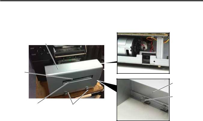
2. PRINTER INSTALLATION
1)Place the printer on the level surface.
2)Keep the slit free or the printer will be overheated. Also keep enough space for replacing and maintenance works while the top cover is opened.
Side panel |
Top Cover |
1- 3
3. NOTE FOR OPTIONAL EQUIPMENT INSTALLATION/MAJOR UNIT REPLACEMENT |
EO18-33027 |
/MAINTENANCE |
|
3.NOTE FOR OPTIONAL EQUIPMENT INSTALLATION/MAJOR UNIT REPLACEMENT/MAINTENANCE
3.NOTE FOR OPTIONAL EQUIPMENT INSTALLATION /MAJOR UNIT REPLACEMENT/MAINTENANCE
WARNING!
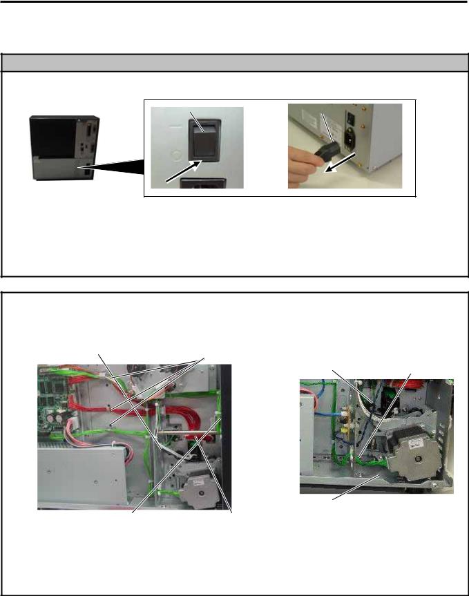
1. Turn the power off and disconnect the power cord before replacing the main parts.
Power Switch |
Power Cord |
2.Never perform disassembling, assembling, and cleaning just after printing. Doing so may cause you to be injured by the print head and the inner parts of the printer being hot.
3.When cleaning the cutter, be careful not to be injured by the cutter blade.
4.Be careful not to pinch your fingers or hands with the covers.
CAUTION!
1.Fix the harnesses and the cord bushes with the cable clamp. Failure to do this may cause the covers to catch them.
Sensor Harness |
Cable Clamp |
|
Cable Clamp |
Stepping Motor Cable |
|
Cord Bush
Operation Panel |
Print Head Harness |
Harness |
|
continued
3-1
3. NOTE FOR OPTIONAL EQUIPMENT INSTALLATION/MAJOR UNIT REPLACEMENT |
EO18-33027 |
/MAINTENANCE |
|
3.NOTE FOR OPTIONAL EQUIPMENT INSTALLATION/MAJOR UNIT REPLACEMENT/MAINTENANCE
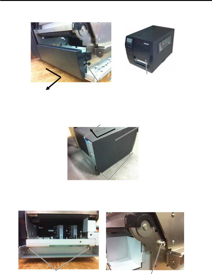
2.Do not remove the screws below. Doing so will require the printer block position adjustment with the jig.
Printer Block
 Screw
Screw
3.Be careful not to damage the sensor window. If so, the sensor cannot detect the feed gap or the black mark correctly, causing improper printing.
Sensor Window
4.When replacing parts or performing maintenance on the printer, be careful not to damage the print head with a hard object like a watch or a ring.
Care must be taken not to allow the metal or glass part of a watch to touch the print head edge.
Care must be taken not to allow a metal object like a ring to touch the print head edge.
Since the print head element can be easily damaged by shock, please treat it carefully by not hitting a hard object against it.
3-2
3. NOTE FOR OPTIONAL EQUIPMENT INSTALLATION/MAJOR UNIT REPLACEMENT |
EO18-33027 |
/MAINTENANCE
3.1 OPENING/CLOSING THE TOP COVER
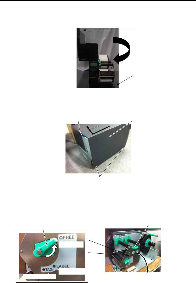
3.1 OPENING/CLOSING THE TOP COVER
When opening the top cover, fully open the top cover to the open position.
When closing, softly close it to the close position.
O p e n p o s i t i o n
Close position
3.2 REMOVING THE SIDE PANEL (L)
Remove the three M3x6 screws from the side panel (L). Move the side panel (L) to the back and push up it to remove.
M3x6 Screw |
Side Panel (L) |
M3x6 Screw
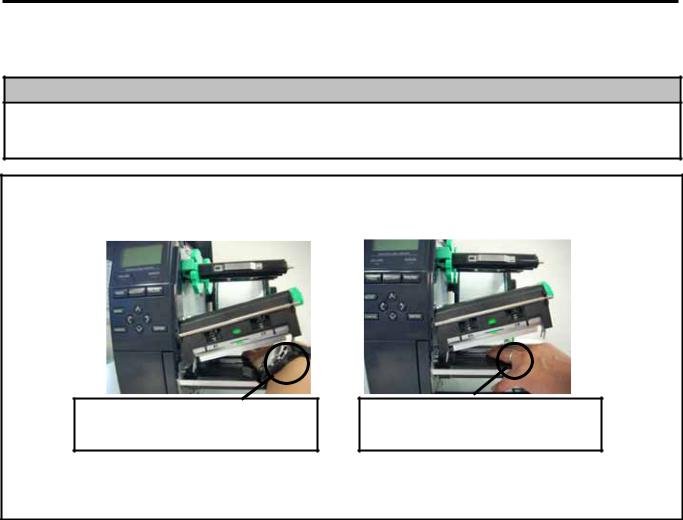
3.3 OPENING/CLOSING THE PRINTER BLOCK
1)Open the top cover.
2)Turn the head lever counterclockwise to Free position.
3)Open the ribbon shaft holder plate.
Ribbon Shaft Holder Plate
Head Lever
Free Position
Lock position (Label)
Lock position (Tag)
3-3
3. NOTE FOR OPTIONAL EQUIPMENT INSTALLATION/MAJOR UNIT REPLACEMENT |
EO18-33027 |
/MAINTENANCE
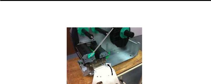
3.3 OPENING/CLOSING THE PRINTER BLOCK
4)Raise the print head block until it stops.
Print Head Block
NOTE: DO NOT excessively push down the print head block to close it. Dosing so may cause a failure of the print head block or damage to the print head.
3-4
3. NOTE FOR OPTIONAL EQUIPMENT INSTALLATION/MAJOR UNIT REPLACEMENT |
EO18-33027 |
/MAINTENANCE
3.4 REMOVING THE OPERATION PANEL
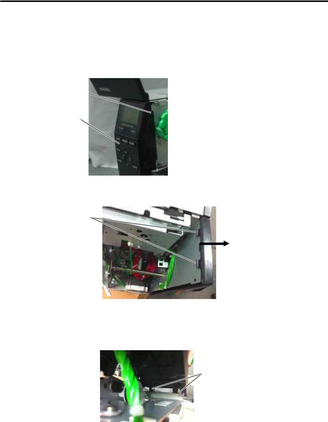
3.4 REMOVING THE OPERATION PANEL
1)Open the top cover. (Refer to section 3.1.)
2)Remove the side panel (L) from the printer. (Refer to section 3.2.)
3)Fully open the top cover, otherwise the operation panel ass’y is stuck on the tab and cannot be removed from the printer.
Tab
 Top Cover
Operation Panel Ass’y
4)Push the operation panel ass’y out through the top hooks direction.
Hooks
5)Lift the operation panel ass’y to release the bottom hook, and then remove the operation panel ass’y by moving it forward.
Hooks
3- 5
3. NOTE FOR OPTIONAL EQUIPMENT INSTALLATION/MAJOR UNIT REPLACEMENT |
EO18-33027 |
/MAINTENANCE
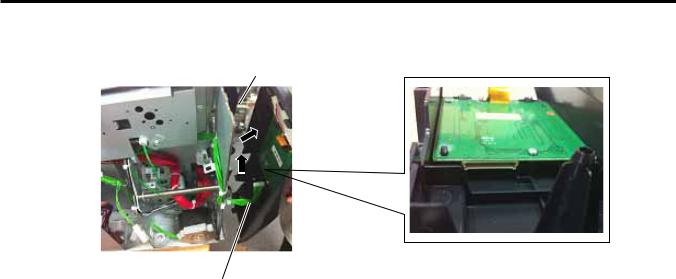
3.4 REMOVING THE OPERATION PANEL
6)Disconnect the operation panel harness from the operation panel ass’y.
Operation Panel Ass’y
Operation Panel Harness
3- 6
4. INSTALLATION PROCEDURE FOR OPTIONAL EQUIPMENT |
EO18-33027 |
4. INSTALLATION PROCEDURE FOR OPTIONAL EQUIPMENT
4.INSTALLATION PROCEDURE FOR OPTIONAL EQUIPMENT
WARNING!
1.Make sure to unplug the power cord before installing the optional equipment.
2.Be careful not to pinch your fingers or hands with the covers.
CAUTION!
When replacing parts or performing maintenance on the printer, be careful not to damage the print head with a hard object like a watch or a ring.
Care must be taken not to allow the metal or glass part of a watch to touch the print head edge.
Care must be taken not to allow a metal object like a ring to touch the print head edge.
Since the print head element can be easily damaged by shock, please treat it carefully by not hitting a hard object against it.
The following optional equipments are provided for this printer.
B-EX204-QM-R: |
Disc cutter |
B-EX904-PK-QM-R: Narrow width platen kit |
B-EX204-R-QM-R: |
Rotary cutter |
B-EX700-WLAN-QM-R: Wireless LAN I/F card |
B-EX904-H-QM-R: |
Peel off module |
B-EX700-RTC-QM-R: RTC/USB host I/F card |
B-EX904-R-QM-R: |
Ribbon Saving Module B-EX700-IO-QM-R: Expansion I/O card |
|
B-EX700-CEN-QM-R: Parallel I/F card |
B-EX700-RS-QM-R: Serial I/F card |
|
B-EX700-RFID-H1-QM-R: HF RFID module mount kit
B-EX700-RFID-U2-EU-R: UHF RFID kit for EU
B-EX700-RFID-U2-US-R: UHF RFID kit for US
B-EX700-RFID-U2-CN-R: UHF RFID kit for CN
In this section, installation procedures for these optional equipments are described.
4- 1
4. INSTALLATION PROCEDURE FOR OPTIONAL EQUIPMENT
EO18-33027
4.1DISC CUTTER (B-EX204-QM-R)
4.1 DISC CUTTER (B-EX204-QM-R)
WARNING!
Be careful not to injure your fingers when installing the cutter unit.
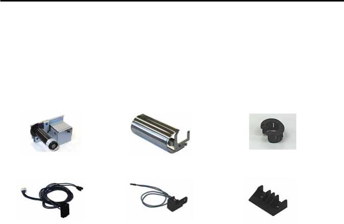
All the following parts are supplied with the kit. Make sure you have all items shown below.
Description |
Q’ty/Unit |
Cutter Unit |
1 |
Cutter Cover |
1 |
Cutter Harness |
1 |
Print Head Cleaner |
1 |
Description |
Q’ty/Unit |
Installation manual |
1 |
Screw (M3x6) |
2 |
Bush |
1 |
|
|
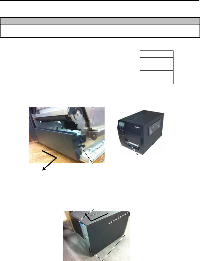
1)Turn the power off and disconnect the power cord.
2)Open the top cover, and push up the hooker and take out the front cover bottom.
Front Plate
Hooker
3)Remove the three M3x6 screws from the side panel (L). Move the side panel (L) to the back and push up it to remove.
M3x6 Screw |
Side Panel (L) |
M3x6 Screw
4- 2

4. INSTALLATION PROCEDURE FOR OPTIONAL EQUIPMENT
EO18-33027
4.1DISC CUTTER (B-EX204-QM-R)
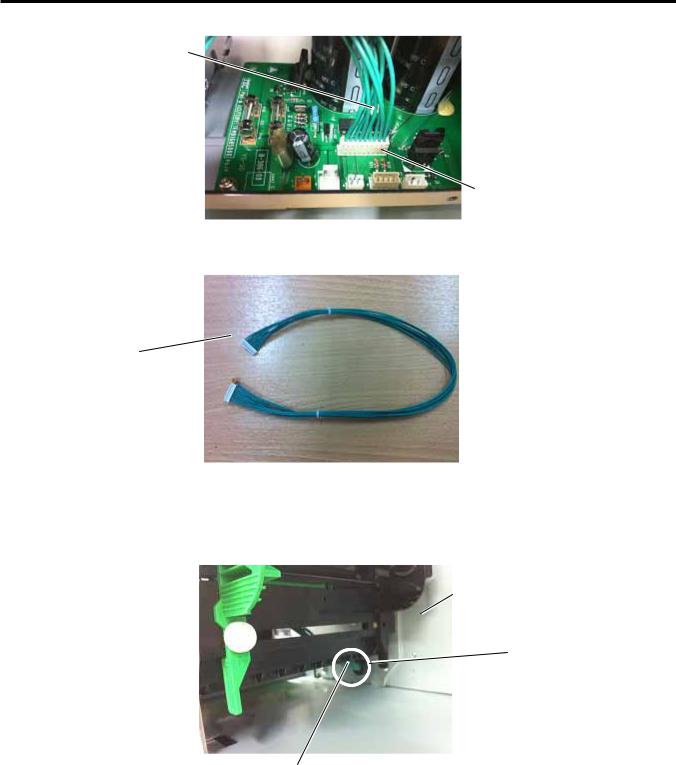
4)Put the cutter in front of the printer. Connect one side of the cutter harness to CN15 on the Main PC Board. And connect another side to the disc cutter PC Board.
Main PC Board |
CN15 |
CN15 |
Disc cutter PC Board |
|
Cutter Harness |
Cutter Harness |
5) Put the cutter on the printer through fit the hooks. And fix it to the printer with the two M4x6 screws.
Hooks |
M3x6 screws |
|
6)Fit the cutter cover on the cutter attachment screws, and fix it to the cutter unit with the two cutter screws.
Screw
7) Reassemble the side panel (L) and close the top cover. Finally check the cutter operation.
4- 3
4. INSTALLATION PROCEDURE FOR OPTIONAL EQUIPMENT
EO18-33027
4.2 ROTARY CUTTER (B-EX204-R-QM-R)
4.2 ROTARY CUTTER (B-EX204-R-QM-R)
WARNING!
Be careful not to injure your fingers when installing the cutter unit.
All the following parts are supplied with the kit. Make sure you have all items shown below.
Description |
Q’ty/Unit |
Description |
Q’ty/Unit |
Cutter Unit |
1 |
Cord Bush |
1 |
Cutter Cover |
1 |
Print Head Cleaner |
1 |
Cutter Drive Unit |
1 |
B-SX Cutter Paper Guide |
1 |
Harness Ass’y (2-pin & 9-pin) |
1 |
SM-4x8 Screw |
5 |
Installation Manual |
1 |
|
|
NOTES:
1.When using the rotary cutter on the B-E4T series, the print speed of 10”/sec. is not supported. Also, when using the rotary cutter, be sure to install the ribbon saving module (B-EX904-R-QM-R). Failure to do this may cause a paper jam or ribbon error. (For the installation procedure, please refer to Section 4.9.)
2.The B B-EX204-R-QM-R with the serial number of 2805Dxxxxxx or earlier cannot be installed on an RFID-ready printer (2804Sxxxxxx or later) without changing some parts of the cutter drive unit. For the parts change procedure, refer to the following:
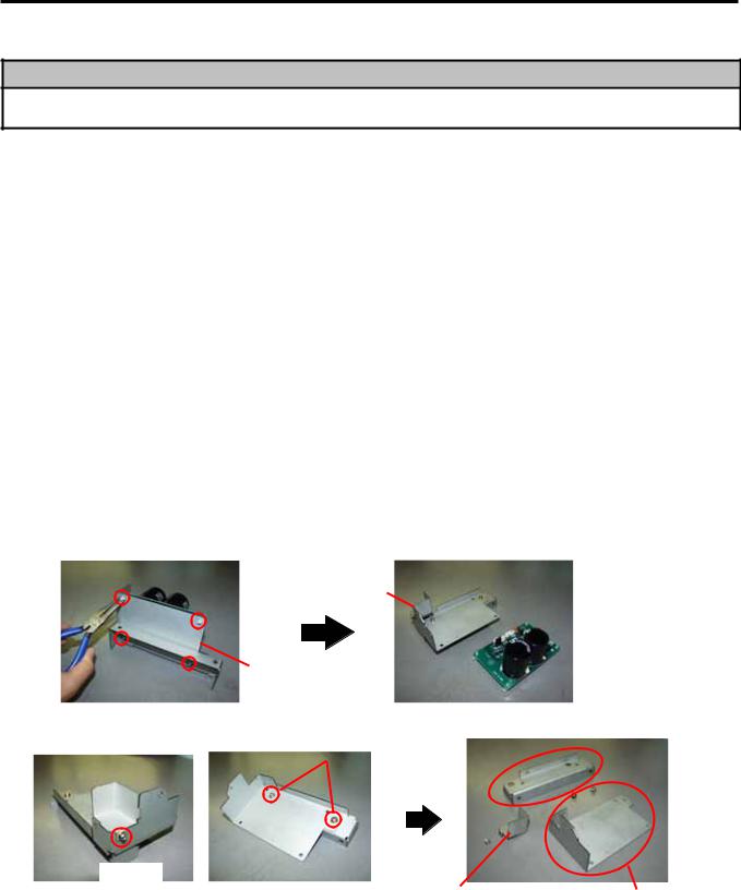
1)Release the four Locking Supports to remove the Rotary Cutter PC Board from the frame.
NOTE: Locking supports are not used. Please discard them.
Frame
Cutter Drive Unit  Rotary Cutter PC Board
2) Disassemble the frame into 3 parts. |
|
Rotary Cutter Guide Plate B |
||
|
|
|
|
|
|
SMW-4x8 |
|
|
|
|
|
|||
SMW-3x6
Rotary Cutter PC Board Cover Rotary Cutter Guide Plate C (To be used later.)
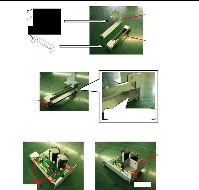
3)Replace the Rotary Cutter Guide Plate B and the Rotary Cutter Guide Plate C with the Rotary Cutter Frame A and Rotary Cutter Frame B, respectively.
4- 4
4. INSTALLATION PROCEDURE FOR OPTIONAL EQUIPMENT |
EO18-33027 |
4.2 ROTARY CUTTER (B-EX204-R-QM-R)
Rotary Cutter Guide Plate C
Rotary Cutter Frame B (P/No.: 7FM01068000)
Rotary Cutter Guide Plate B
Rotary Cutter Frame A (P/No.: 7FM0167000)
4)Assemble the Rotary Cutter Frame A and Rotary Cutter Frame B with an SMW-4x8 screw removed in step 2).
SMW-4x8
Determine the position by fitting the two parts here.
5)Confirming the orientation of the Rotary Cutter PC Board, fix it to the Rotary Cutter Frames A and B with three SMW-3x6 screws. Then, attach the Rotary Cutter PC Board Cover with an SMW-3x6 screw.
Rotary Cutter PC
Board Cover
SMW-3x6
SMW-3x6
4- 5
4. INSTALLATION PROCEDURE FOR OPTIONAL EQUIPMENT
EO18-33027
4.2 ROTARY CUTTER (B-EX204-R-QM-R)
NOTE: When attaching the B-8204-QM cutter module, replace the original cutter paper guide C with the enclosed B-SX cutter paper guide C using the following procedure.
CAUTION!
Do not hold the cutter paper guides when attaching the Cutter Unit to the printer. Doing so may deform the cutter paper guides, causing a paper jam.
DO NOT!
 Cutter Paper Guide
(1) Remove the two M-4x6 Set Screws from the cutter unit to detach the cutter paper guide C.
M-4x6
Cutter Paper Guide C
(2) Secure the B-SX cutter paper guide C with the M-4x6 set screws while pushing it upward.
M-4x6
B-SX Cutter
Paper Guide C
4- 6
4. INSTALLATION PROCEDURE FOR OPTIONAL EQUIPMENT
EO18-33027
4.2 ROTARY CUTTER (B-EX204-R-QM-R)
1)Turn the power off and disconnect the power cord.
2)Open the top cover, and push up the hooker and take out the front cover bottom.
Front Plate
Hooker
3)Remove the three M3x6 screws from the side panel (L). Move the side panel (L) to the back and push up it to remove.
M3x6 Screw |
Side Panel (L) |
M3x6 Screw
4) Fix the cutter drive unit to the printer with the three M-4x8 screws.
M-4x8 Screw |
M-4x8 Screw |
4- 7
4. INSTALLATION PROCEDURE FOR OPTIONAL EQUIPMENT
EO18-33027
4.2 ROTARY CUTTER (B-EX204-R-QM-R)
5) Connect the 9-pin connector of the harness ass’y to CN7 on the cutter driver unit, respectively.
Harness Ass’y
CN7 (9 pins)
6) Fit the bush to the harness ass’y in the orientation as shown below.
Harness Ass’y
7)Insert the harness ass’y into the hole in the main frame. Fit the bush into the hole.
Main Frame
Hole
Harness Ass’y
4- 8
4. INSTALLATION PROCEDURE FOR OPTIONAL EQUIPMENT
EO18-33027
4.2 ROTARY CUTTER (B-EX204-R-QM-R)
8)Fix the harness ass’y with the clamp.
9)Connect the 9-pin connector of the harness ass’y to CN15, and 2-pin connector to CN18 on the
Main PC board, respectively. |
Main PC Board |
|
|
CN15 (9 pins) |
|
Harness Ass’y
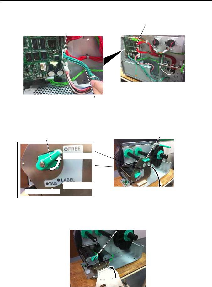
10)Turn the head lever counterclockwise to Free position.
11)Open the ribbon shaft holder plate.
Ribbon Shaft Holder Plate
Head Lever
Free Position
Lock position (Label)
Lock position (Tag)
12) Raise the print head block until it stops.
Print Head Block
4- 9
4. INSTALLATION PROCEDURE FOR OPTIONAL EQUIPMENT
EO18-33027
4.2 ROTARY CUTTER (B-EX204-R-QM-R)
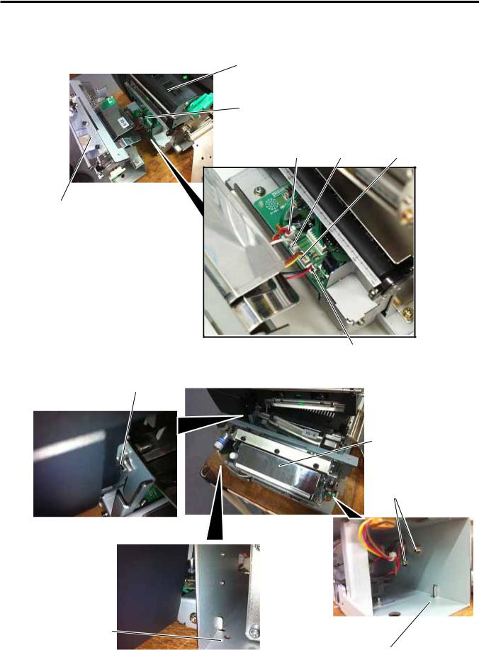
13)Connect the four harnesses of the cutter unit to CN8, CN10, CN11 and CN12 on the cutter drive unit.
Print Head Block
Cutter Drive Unit
CN8 |
CN12 |
CN10 |
Cutter Unit
CN11
14)Fit the two tabs of the cutter drive unit into the notches, and then fix the cutter unit with the three SM-4x8 screws. SM-4 x 8 Screw
Cutter Unit
SM-4 x 8 Screw
Notch
Notch
4- 10
4. INSTALLATION PROCEDURE FOR OPTIONAL EQUIPMENT
EO18-33027
4.2 ROTARY CUTTER (B-EX204-R-QM-R)
15)Attach the cutter cover to the cutter unit with the two screws so that the tab of the cutter cover turns on the cutter cover open switch.
NOTES: 1. Be careful not to pinch the cutter harness by the cutter cover.
2.Make sure that the anti-static brush is protruding from the media outlet.
Cutter Cover
 Cutter Cover
Open Switch
Anti-static
Brush
Cutter Cover
Tab
Media Outlet |
Screw |
|
16) Close the print head block and ribbon shaft holder plate.
NOTE: DO NOT excessively push down the print head block to close it. Doing so may cause a failure of the print head block or damage to the print head.
17) Reassemble the side panel (L) and close the top cover. Finally check the cutter operation.
4-11
4. INSTALLATION PROCEDURE FOR OPTIONAL EQUIPMENT
EO18-33027
4.3 PEEL OFF MODULE (B-EX904-H-QM-R)
4.3 PEEL OFF MODULE (B-EX904-H-QM-R)
This optional device is used for strip print, which cannot be used together with either B-EX204-QM-R or B-EX204-R-QM-R.
When using a strip module together with an RFID module, be sure to install the RFID module prior to the strip module.
All the following parts are supplied with the kit. Make sure you have all items shown below.
Rewinder Ass’y (1 pc.) |
Rewinder Guide Plate (1 pc.) |
Bush (1 pc.) |
|
|
|
Strip Sensor (TR) (1 pc.) |
Strip Sensor (LED) (1 pc.) |
Rewind Paper Guide (1 pc.) |
|
|
|
•Installation Manual (1 copy)
•SM-4x8B Screw (10 pcs.)
•SM-3x6B Screw (1 pc.)
•SM-4x8C Screw (1 pc.)
4-12

4. INSTALLATION PROCEDURE FOR OPTIONAL EQUIPMENT
EO18-33027
4.3 PEEL OFF MODULE (B-EX904-H-QM-R)
1)Turn the power off and disconnect the power cord.
2)Open the top cover, and push up the hooker and take out the front cover bottom.
Front Plate
Hooker
3)Remove the three M3x6 screws from the side panel (L). Move the side panel (L) to the back and push up it to remove.
M3x6 Screw |
Side Panel (L) |
M3x6 Screw
4) Lock off the hook and remove the iron sheet.
Hook
4-13
4. INSTALLATION PROCEDURE FOR OPTIONAL EQUIPMENT
EO18-33027
4.3 PEEL OFF MODULE (B-EX904-H-QM-R)
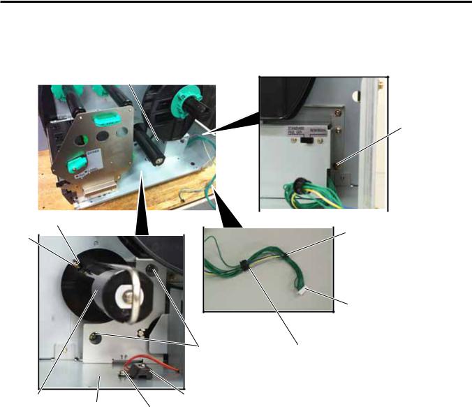
5)Align the notch of the take-up holder with the screw hole of the rewinder ass’y, and attach them to the printer with the four M-3x6 screws and the M-3x6 screw.
6)Attach the rewind full sensor (LED) to the base with the SM-3x6 screw.
7)Fit the bush to the longer harness of the rewind full sensor (Tr) and the rewinder harness in the orientation shown below.
Rewinder Ass’y
 M3x6 Screw
M3x6 Screw |
|
|
|
|||
|
Longer Harness of the Rewind |
|||||
Notch |
|
|
|
|
||
|
|
|
|
|||
|
|
|
Full Sensor (Tr) |
|||
|
|
|||||
|
|
|
|
|
||
Rewinder Harness
M3x6 Screw |
Bush |
Take-up Holder |
Base |
Rewind Full Sensor (LED) |
|
M-3x6 Screw |
|||
|
|||
|
|
4-14
4. INSTALLATION PROCEDURE FOR OPTIONAL EQUIPMENT
EO18-33027
4.3 PEEL OFF MODULE (B-EX904-H-QM-R)
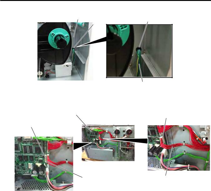
8)Insert the longer harness of the rewind full sensor (Tr) into the hole in the printer frame. Fit the bush into the hole.
Frame |
Bush |
|
|
|
Hole |
Longer Harness of the Rewind Full Sensor (Tr)
9)Connect the longer harness of the rewind full sensor (Tr)and the rewinder harness to CN4 and CN15 on the Main PC board.
Main PC Board |
CN15 |
|
CN4
Longer Harness of the |
Rewinder Harness |
|
Rewind Full Sensor (Tr) |
||
|
4-15
 Loading...