


 Loading...
Multimedia Projector
MODEL PLV-Z700
Owner’s Manual

Features and Design
This Multimedia Projector is designed with the most advanced technology for portability, durability, and ease of use. It uses built-in multimedia features, a palette of 1.07 billion colors, and matrix liquid crystal display (LCD) technology.
Short Throw & Wide-Range Zoom Lens |
Automatic Slide Shutter |
||
|
|
|
|
The 2x Short Throw & Wide-Range Zoom Lens is capable of throwing a 100” diagonal image from a distance of 9.8’ (3.0 m) to 20.0’ (6.1 m).
The automatic slide shutter protects the lens from dust and scratches. It opens and closes automatically as you press the POWER ON/STAND-BY button.
Lens Shift
The Lens Shift function provides a greater installation flexibility. You can use the projector at desired places without images being distorted (see page 14).
Color Management
The Color management function allows you to adjust the details of picture colors to suit your preference and viewing environments (see pages 32 – 33).
Wide Selection of Image Modes
You can select an ideal image mode for the viewing environment or for your desired picture quality (see page 27). The five different kinds of images of your choice can also be stored (see pages 28 – 33).
Power Management
The Power management function reduces power consumption and maintains the lamp life (see page 41).
Auto Iris
The integration of the lamp aperture enhances the contrast and depth of the projected image.
Compatibility
The projector accepts signals from multiple sources: computers, analog TV systems (PAL, SECAM, NTSC, NTSC4.43, PAL-M, and PAL-N), component video, S-video, RGB scart, and HDMI.
Logo
The Logo function allows you to customize the screen logo (see page 40). You can capture an image for the screen logo and use it for the starting-up display or between presentations.
Lamp Control
The brightness of the projection lamp can be selected (see pages 23, 29).
Simple Computer System Setting
The Multi-scan system of the projector conforms to almost all computer output signals quickly (see page 26).
16 : 9 Wide Screen
The wide LCD panels with 1920 x 1080 resolution (16:9 aspect ratio) can project the image from component video signals such as DVD players and HDTV devices in full screen.
Multi-language Menu Display
Operation menu is available in 16 languages: English, German, French, Italian, Spanish, Portuguese, Dutch, Swedish, Finnish, Polish, Hungarian, Romanian, Russian, Chinese, Korean, and Japanese (see page 37).
Two HDMI Terminals
The projector has two HDMI (High Definition Multimedia Interface) terminals. Simple connection with digital equipment is offered through these terminals.
Interlace-Progressive Conversion
High-quality picture technology is available that converts an interlaced signal into a progressively-scanned one (see page 29).
Note:
•The On-Screen Menu and figures in this manual may differ slightly from the actual product.
•The contents of this manual are subject to change without notice.
2

Table of Contents
Features and Design . . . . . . . . . . |
. |
. 2. . . Input. . |
. . . . . . . . . . . . . . . . |
. . |
|
. 24. . . . . . . . |
|||
Table of Contents . . . . . . . . . . |
. |
3. . . . . . |
|
|
|
24 |
|||
|
|
|
|
|
Input Source and System Selection |
|
|
||
To the Owner . . . . . . . . . . . . |
. |
. |
|
|
Image . . . . . . . . . . . . . . . . |
. |
. |
27. . . . . . . . |
|
4. . . . . . . |
|
|
|
|
|||||
Safety Instructions . . . . . . . . . . |
. |
|
|
|
Image Mode Selection |
|
|
27 |
|
|
.5 . . . . . |
|
|
|
|
||||
Air Circulation |
|
|
6 |
|
Image Adjustment . . . . . . . . |
. . |
|
. 28. . . . . |
|
Installing the Projector in Proper Position |
|
|
6 |
|
Image Mode Adjustment |
|
|
28 |
|
Moving the Projector |
|
|
6 |
|
Picture Adjustment . . . . . . . . |
. . |
|
. 34. . . . . |
|
Compliance . . . . . . . . . . . . . . . |
|
.7 . . . . . . . |
|
|
34 |
||||
|
|
|
|
|
Picture Position and Screen Adjustment |
|
|
||
Part Names and Functions . . . . . . |
. |
|
.8 . |
. |
. Screen . . . . . . . . . . . . . . . |
. |
. |
.35. . . . . . . |
|
Front |
|
|
8 |
|
Screen Size Adjustment |
|
|
35 |
|
Back |
|
|
8 |
|
Setting . . . . . . . . . . . . . . . |
. |
. |
.37. . . . . . . |
|
Bottom |
|
|
8 |
|
Setting |
|
|
37 |
|
Rear Terminal |
|
|
9 |
|
Information . . . . . . . . . . . . |
. . |
|
. 43. . . . . . . |
|
Top Control |
|
|
10 |
|
Input Source Information Display |
|
|
43 |
|
Remote Control |
|
|
11 |
|
Maintenance and Cleaning . . . . |
. |
. 44. . . |
||
Remote Control Operating Range |
|
|
12 |
|
|||||
|
|
|
Warning Indicator |
|
|
44 |
|||
Remote Control Battery Installation |
|
|
12 |
|
|
|
|||
|
|
|
Cleaning the RGB panels |
|
|
45 |
|||
|
|
|
|
|
|
|
|||
Installation . . . . . . . . . . . . . . |
. 13. . . . . . . |
|
|
|
47 |
||||
|
|
|
|
|
Cleaning the Air Filter |
|
|
||
Positioning the Projector |
|
|
13 |
|
Resetting the Filter Counter |
|
|
48 |
|
Adjustable Feet |
|
|
13 |
|
Cleaning the Projection Lens |
|
|
48 |
|
Moving the Lens |
|
|
14 |
|
Cleaning the Projector Cabinet |
|
|
48 |
|
Connecting to Video Equipment (Video, S-Video) |
|
|
15 |
|
Lamp Replacement |
|
|
49 |
|
Connecting to Video Equipment (Component) |
|
|
15 |
|
Resetting the Lamp Replacement Counter |
|
|
50 |
|
Connecting to Video Equipment (HDMI, RGB Scart) 16 |
|
Appendix . . . . . . . . . . . . . . . . 51. . . . . . . . |
|||||||
Connecting to a Computer |
|
|
16 |
|
|||||
|
|
|
Troubleshooting |
|
|
51 |
|||
Connecting the AC Power Cord |
|
|
17 |
|
|
|
|||
|
|
|
Indicators and Projector Condition |
|
|
53 |
|||
|
|
|
|
|
|
|
|||
Basic Operation . . . . . . . . . . . |
. |
18. . |
. |
. . .Menu Tree |
|
|
54 |
||
Turning On the Projector |
|
|
18 |
|
System Mode Chart |
|
|
56 |
|
Turning Off the Projector |
|
|
19 |
|
Technical Specifications |
|
|
57 |
|
How to Operate the On-Screen Menu |
|
|
20 |
|
Configurations of Terminals |
|
|
58 |
|
Menu and its Functions |
|
|
21 |
|
Optional Parts |
|
|
58 |
|
Zoom and Focus Adjustment |
|
|
22 |
|
Dimensions |
|
|
59 |
|
Remote Control Operation |
|
|
22 |
|
|
|
|
|
|
TRADEMARKS
●Each name of corporations or products in this owner’s manual is either a trademark or a registered trademark of its respective corporation.
3
To the Owner
Before installing and operating the projector, read this manual thoroughly.
The projector provides many convenient features and functions. Operating the projector properly enables you to manage those features and maintains it in good condition for many years to come.
Improper operation may result in not only shortening the product life, but also malfunctions, fire hazard, or other accidents.
If your projector seems to operate improperly, read this manual again, check operations and cable connections and try the solutions in the “Troubleshooting” section in the back of this manual. If the problem still persists, contact the dealer where you purchased the projector or the service center.
CAUTION
RISK OF ELECTRIC SHOCK
DO NOT OPEN
CAUTION:TO REDUCE THE RISK OF ELECTRIC SHOCK, DO NOT REMOVE COVER (OR BACK).. NO USER-SERVICEABLE PARTS INSIDE EXCEPT LAMP REPLACEMENT.. REFER SERVICING TO QUALIFIED SERVICE PERSONNEL..
THIS SYMBOL INDICATES THAT DANGEROUS VOLTAGE CONSTITUTING A RISK OF ELECTRIC SHOCK IS PRESENT WITHIN THIS UNIT..
THIS SYMBOL INDICATES THAT THERE
ARE IMPORTANT OPERATING AND
MAINTENANCE INSTRUCTIONS IN THE
OWNER'S MANUAL WITH THIS UNIT..
The symbol mark and recycling systems described below apply to EU countries and do not apply to countries in other areas of the world.
Your SANYO product is designed and manufactured with high quality materials and components which can be recycled and/ or reused.
The symbol mark means that electrical and electronic equipment, batteries and accumulators, at their end-of- life, should be disposed of separately from your household waste.
Note:
If a chemical symbol is printed beneath the symbol mark, this chemical symbol means that the battery or accumulator contains a heavy metal at a certain concentration. This will be indicated as follows: Hg: mercury, Cd: cadmium, Pb: lead
In the European Union there are separate collection systems for used electrical and electronic equipment,
batteries and accumulators.
Please, dispose of them correctly at your local community waste collection/recycling centre.
Please, help us to conserve the environment we live in!
READ AND KEEP THIS OWNER’S MANUAL FOR LATER USE..
Safety Precaution
WARNING: ●THIS APPARATUS MUST BE EARTHED..
●TO REDUCE THE RISK OF FIRE OR ELECTRIC SHOCK, DO NOT EXPOSE THIS APPLIANCE TO RAIN OR MOISTURE..
–This projector produces intense light from the projection lens. Avoid staring directly into the lens as much as possible, otherwise eye damage could result. Be especially careful that children do not stare directly into the beam.
–Install the projector in a proper position. Otherwise it may result in fire hazard.
–Allowing the proper amount of space on the top, sides,
and rear of the projector cabinet is critical for proper air circulation and cooling of the unit. The dimensions shown here indicate the minimum space required. If the projector is to be built into a compartment or similarly enclosed, these minimum distances must be maintained.
–To not cover the ventilation slot on the projector. Heat buildup can reduce the service life of your projector, and can also
be dangerous.
SIDE and TOP |
REAR |
1.5' (50 cm)
3' (1 m) |
1.5' (50 cm) |
1.5' (50 cm) |
–If the projector is unused for an extended time, unplug the projector from the power outlet.
–Do not project the same image for a long time. The afterimage may remain on the LCD panels by the characteristic of panel.
 CAUTION ON HANGING FROM THE CEILING
When hanging the projector from the ceiling, clean the air intake vents, air filters, and the top of the projector periodically with a vacuum cleaner. If you leave the projector unclean for a long time, the cooling fans can be clogged with dust, and it may cause a breakdown or a disaster.
Do not set the projector in greasy, wet, or smoky conditions such as IN a kitchen to prevent A Breakdown or disaster.. If the projector comes in contact with oil or chemicals, it may become deteriorated..
CAUTION
Not for use in a computer room as defined in the Standard for the Protection of Electronic Computer/Data Processing Equipment, ANSI/NFPA 75.
Ne peut être utilisé dans une salle d’ordinateurs telle que définie dans la norme ANSI/NFPA 75 Standard for Protection of Electronic Computer/Data Processing Equipment.
4
Safety Instructions
All the safety and operating instructions should be read before the product is operated.
Read all of the instructions given here and retain them for later use. Unplug this projector from AC power supply before cleaning. Do not use liquid or aerosol cleaners. Use a damp cloth for cleaning.
Follow all warnings and instructions marked on the projector.
For added protection to the projector during lightning storm, or when it is left unattended and unused for long periods of time, unplug it from the wall outlet. This will prevent damage due to lightning and power line surges.
Do not expose this unit to rain or use near water... for
example, in a wet basement, near a swimming pool, etc...
Do not use attachments not recommended by the manufacturer as they may cause hazards.
Do not place this projector on an unstable cart, stand, or table. The projector may fall, causing serious injury to a child or adult, and serious damage to the projector. Use only with a cart or stand recommended by the manufacturer, or sold with the projector. Wall or shelf mounting should follow the manufacturer’s instructions, and should use a mounting kit approved by the manufacturers.
An appliance and cart combination should be moved with care. Quick stops, excessive force, and uneven surfaces may cause the appliance and cart combination to overturn.
Slots and openings in the back and bottom of the cabinet are provided for ventilation, to ensure reliable operation of the equipment and to protect it from overheating.
The openings should never be covered with cloth or other materials, and the bottom opening should not be blocked by placing the projector on a bed, sofa, rug, or other similar surface. This projector should never be placed near or over a radiator or heat register.
This projector should not be placed in a built-in installation such as a bookcase unless proper ventilation is provided.
Never push objects of any kind into this projector through cabinet slots as they may touch dangerous voltage points or short out parts that could result in a fire or electric shock. Never spill liquid of any kind on the projector.
Do not install the projector near the ventilation duct of airconditioning equipment.
This projector should be operated only from the type of power source indicated on the marking label. If you are not sure of the type of power supplied, consult your authorized dealer or local power company.
Do not overload wall outlets and extension cords as this can result in fire or electric shock. Do not allow anything to rest on the power cord. Do not locate this projector where the cord may be damaged by persons walking on it.
Do not attempt to service this projector yourself as opening or removing covers may expose you to dangerous voltage or other hazards. Refer all servicing to qualified service personnel.
Unplug this projector from wall outlet and refer servicing to qualified service personnel under the following conditions:
a.When the power cord or plug is damaged or frayed.
b.If liquid has been spilled into the projector.
c.If the projector has been exposed to rain or water.
d.If the projector does not operate normally by following the operating instructions. Adjust only those controls that are covered by the operating instructions as improper
adjustment of other controls may result in damage and will often require extensive work by a qualified technician to restore the projector to normal operation.
e.If the projector has been dropped or the cabinet has been damaged.
f.When the projector exhibits a distinct change in performance, this indicates a need for service.
When replacement parts are required, be sure the service technician has used replacement parts specified by the manufacturer that have the same characteristics as the original part. Unauthorized substitutions may result in fire, electric shock, or injury to persons.
Upon completion of any service or repairs to this projector, ask the service technician to perform routine safety checks to determine that the projector is in safe operating condition.
NOTE FOR CUSTOMERS IN THE US
Hg LAMP(S) inside this product contain mercury and must be recycled or disposed ofaccording to local, state or federal laws.
5
Safety Instructions
Air Circulation
Openings in the cabinet are provided for ventilation. To ensure reliable operation of the product and to protect it from overheating, these openings must not be blocked or covered.
 CAUTION
Hot air is exhausted from the exhaust vent. When using or installing the projector, the following precautions should be taken.
–Do not put any flammable objects or spray can near the projector. Hot air is exhausted from the ventilation holes.
–Keep the exhaust vent at least 3’ (1 m) away from any objects.
–Do not touch a peripheral part of the exhaust vent, especially screws and metallic part. This area will become hot while the projector is being used.
–Do not put anything on the projector. Objects put on the cabinet will not only get damaged but also cause fire hazard by heat.
Cooling fans are provided to cool down the projector. The fan’s running speed is changed according to the temperature inside the projector.
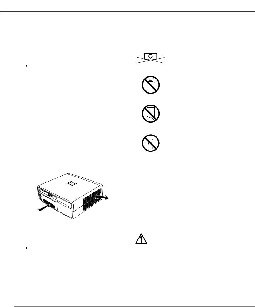
Installing the Projector in Proper Position
Install the projector properly. Improper installation may reduce the lamp life and cause fire hazard.
20˚
20˚
NO UPWARD
Do not tilt the projector more than 20 degrees from side to side.
Do not point the projector up to project an image.
Do not point the projector down to project an image.
NO DOWNWARD
Do not put the projector on either side to project an image.
NO SIDEWARD
Air Intake Vent |
Exhaust Vent |
(Hot air exhaust) |
 CAUTION ON CEILING MOUNTING
For ceiling mounting, you need the ceiling mount kit designed for this projector. When not mounted properly, the projector may fall, causing hazards or injury. For details, consult your dealer. The warranty on this projector does not cover any damage caused by use of any nonrecommended ceiling mount kit or installation of the ceiling mount kit in an improper location.
Moving the Projector
When moving the projector, make sure that the automatic slide shutter is closed, retract the adjustable feet, and lock the lens with the Lens Shift Lock to prevent damage to the lens and cabinet.
When the projector is unused for an extended period, put it into a suitable case.
Care must be taken when handling the projector; do not drop, bump, subject it to strong forces, or put other things on the cabinet.
CAUTION IN CARRYING OR TRANSPORTING THE PROJECTOR
–Do not drop or bump the projector, otherwise damages or malfunctions may result.
–When carrying the projector, use a suitable carrying case.
–Do not transport the projector by courier or any other transport service in an unsuitable transport case. This may cause damage to the projector. For information about transporting the projector by courier or any other transport service, consult your dealer.
–Do not put the projector in a case before it is cooled enough.
6
Compliance
Federal Communications Commission Notice
This equipment has been tested and found to comply with the limits for a Class B digital device, pursuant to Part 15 of the FCC Rules. These limits are designed to provide reasonable protection against harmful interference in a residential installation. This equipment generates, uses, and can radiate radio frequency energy. If it is not installed and used in accordance with the instructions, it may cause harmful interference to radio communications. However, there is no guarantee that interference will not occur in a particular installation. If this equipment does cause harmful interference to radio or television reception, which can be determined by turning the equipment off and on, the user is encouraged to try to correct the interference by one or more of the following measures:
–Reorient or relocate the receiving antenna.
–Increase the separation between the equipment and receiver.
–Connect the equipment into an outlet on a circuit different from that to which the receiver is connected.
–Consult the dealer or an experienced radio/TV technician for help.
Use of shielded cable is required to comply with class B limits in Subpart B of Part 15 of FCC Rules.
Do not make any changes or modifications to the equipment unless otherwise specified in the instructions. If such changes or modifications should be made, you could be required to stop operation of the equipment.
Model Number(s) |
: PLV-Z700 |
Trade Name |
: Sanyo |
Responsible party |
: SANYO FISHER COMPANY |
Address |
: 21605 Plummer Street, Chatsworth, California 91311 |
Telephone No. |
: (818)998-7322 |
AC Power Cord Requirement
The AC Power Cord supplied with this projector meets the requirement for use in the country you purchased it.
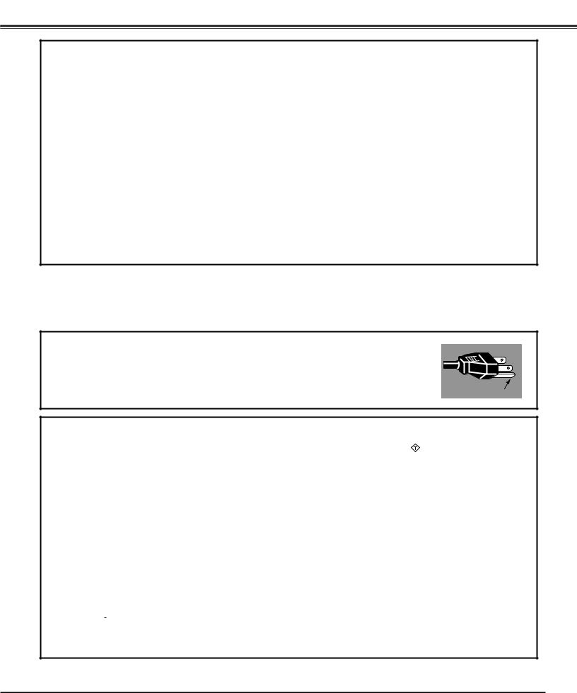
AC Power Cord for the United States and Canada:
AC Power Cord used in the United States and Canada is listed by the Underwriters Laboratories (UL) and certified by the Canadian Standard Association (CSA).
AC Power Cord has a grounding-type AC line plug. This is a safety feature to be sure that the plug will fit into the power outlet. Do not try to defeat this safety feature. Should you be unable to insert the plug into the outlet,
contact your electrician. |
GROUND |
|
AC Power Cord for the United Kingdom:
This cord is already fitted with a moulded plug incorporating a fuse, the value of which is indicated on the pin face of the plug. Should the
fuse need to be replaced, an ASTA approved BS 1362 fuse must be used of the same rating, marked thus |
ASA . If the fuse cover is |
detachable, never use the plug with the cover omitted. If a replacement fuse cover is required, ensure it |
is of the same colour as that |
visible on the pin face of the plug (i.e. red or orange). Fuse covers are available from the Parts Department indicated in your User Instructions.
If the plug supplied is not suitable for your socket outlet, it should be cut off and destroyed. The end of the flexible cord should be suitably prepared and the correct plug fitted.
WARNING: A PLUG WITH BARED FLEXIBLE CORD IS HAZARDOUS IF ENGAGED IN A LIVE SOCKET OUTLET..
The Wires in this mains lead are coloured in accordance with the following code: Green-and-yellow ············ Earth
Blue ································· Neutral Brown ······························ Live
As the colours of the wires in the mains lead of this apparatus may not correspond with the coloured markings identifying the terminals in your plug proceed as follows:
The wire which is coloured green-and-yellow must be connected to the terminal in the plug which is marked by the letter E or by the safety
earth symbol |
|
|
or coloured green or green-and-yellow. |
|
|
The wire which is coloured blue must be connected to the terminal which is marked with the letter N or coloured black. The wire which is coloured brown must be connected to the terminal which is marked with the letter L or coloured red.
WARNING:THIS APPARATUS MUST BE EARTHED..
THE SOCKET-OUTLET SHOULD BE INSTALLED NEAR THE EQUIPMENT AND EASILY ACCESSIBLE..
7
Part Names and Functions
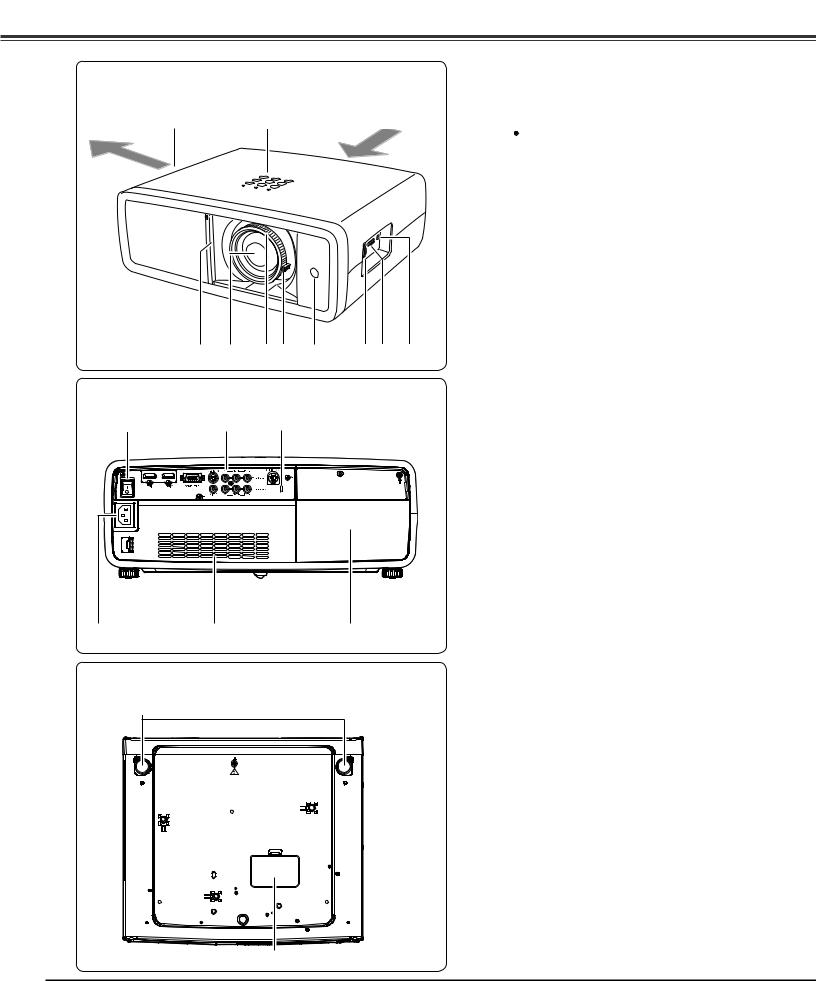
Front
q |
w |
Air flow |
e |
r |
t y |
u |
i o |
!0 |
Back |
|
|
|
|
|
!2 |
!1 |
|
|
|
|
!3 |
!4 |
|
|
!5 |
|
Bottom |
!6 |
!7 |
q Exhaust Vent
 CAUTION
Hot air is exhausted from the exhaust vent. Do not put heat-sensitive objects near this side.
w Top Controls and Indicators
e Automatic Slide Shutter
r Projection Lens
t Focus Ring
y Zoom Lever
u Infrared Remote Receiver
i Vertical Lens Shift Ring (Up/Down)
o Horizontal Lens Shift Ring (Left/Right)
!0Lens Shift Lock
!1Terminals and Connectors
!2Main On/Off Switch
!3Power Cord Connector
!4Air Intake Vent
!5Lamp Cover
Kensington Security Slot
This slot is for a Kensington lock used to deter theft of
the projector.
*Kensington is a registered trademark of ACCO Brands Corporation.
!6Adjustable Feet
!7RGB Panel Cleaning Hole Cover
8
Part Names and Functions
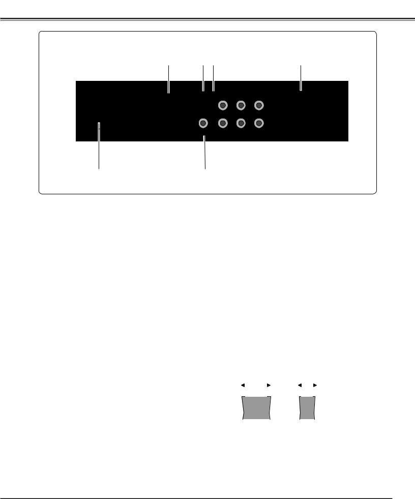
Rear Terminal
q |
w e |
r |
t |
y |
qCOMPUTER
Connect the computer output signal, or RGB Scart 21-pin video output to this connector (p.16).
wS-VIDEO
Connect the S-Video output signal from video equipment to this jack (p.15).
e COMPONENT 1 or COMPONENT 2
Connect the component video output signal to these jacks (p.15).
rSERVICE PORT
This jack is used to service the projector.
tHDMI 1/HDMI 2*
Connect the HDMI output signal from video equipment to these terminals (p.16).
yVIDEO
Connect the composite video output signal from video equipment to this jack (p.15).
*Note on the HDMI connector:
Use the HDMI connector less than the size shown below. Otherwise you cannot connect use HDMI 1 and HDMI 2 terminals at the same time.
Maximum dimensions of the HDMI connectors
0.94" (24 mm) |
0.59" (15 mm) |
|||||||||
|
|
|
|
|
|
|
|
|
|
|
|
|
|
|
|
|
|
|
|
|
|
|
|
|
|
|
|
|
|
|
|
|
|
|
|
|
|
|
|
|
|
|
|
WIDTH THICKNESS
9
Part Names and Functions
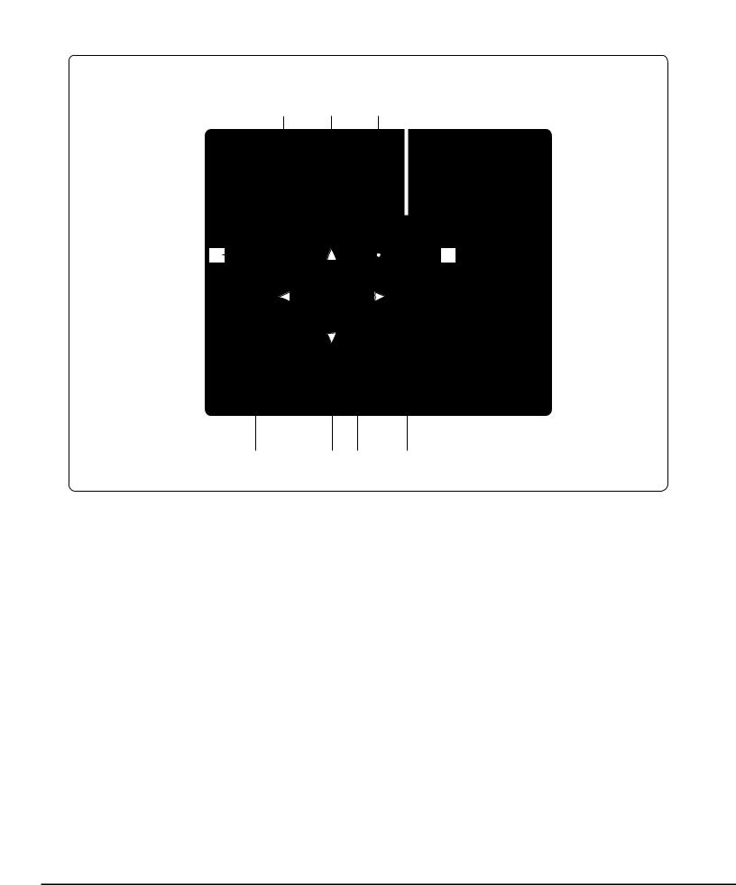
Top Control
e w q
r |
o |
t |
y u |
i |
qPOWER indicator
–Lights red while the projector is in stand-by mode.
–Lights green during operations.
–Blinks red during the cooling-off period.
–Blinks green in the Power management mode (p.41).
–Blinks orange when the automatic slide shutter is closed during operations (p.53).
wWARNING indicator
–Lights red light when the projector detects an abnormal condition.
–Blinks red when the internal temperature of the projector exceeds the operating range (pp.44, 53).
eLAMP REPLACE indicator
Lights yellow light when the projection lamp reaches its end of life (pp.49, 53).
rMENU button
Open or close the On-Screen Menu (p.20).
tINPUT button
Select an input source (p.24).
yPOINT ed78 buttons
Select an item or adjust the setting values in the OnScreen Menu.
uOK button
Execute the item selected or use it to access the submenu items (p.20).
iINFO.. button
Display the input source information (p.43).
oPOWER ON/STAND-BY button
Turn the projector on or off (pp.18, 19).
10
Part Names and Functions
Remote Control
e w q
r |
@1 |
qPOWER ON/STAND-BY button
Turn the projector on or off (pp.18, 19).
wRESET button
Reset to the previous figure.
This function is limited to when selecting the Image Adjustment (pp.28 – 33) and Picture Adjustment (p.34).
eLIGHT button
Light up the remote control buttons for about 10 seconds (p.22).
rMENU button
Open or close the On-Screen Menu (p.20).
tPOINT ed78 buttons
Select an item or adjust the setting values in the On-Screen Menu.
|
@0 |
t |
|
y |
!9 |
|
!8 |
ySCREEN button
Select a screen size (pp.22, 35).
uBRIGHTNESS button
Adjust the brightness of a projected image (pp.23, 28).
iINPUT buttons
Select an input source (p.24).
oLAMP CONTROL button
Select a lamp mode (pp.23, 29).
u |
!0FREEZE button |
|
!7 |
Freeze the projected image (p.23). |
|
!6 |
!1NO SHOW button |
|
!5 |
Temporarily turn off the projected image (p.23). |
|
|
!2LOGO button |
|
!4 |
Display the captured logo (p.23). |
|
i |
!3COLOR TEMP.. button |
|
!3 |
||
Adjust the color temperature of a projected image (p.28). |
||
|
||
!2 |
!4SHARPNESS button |
|
|
||
!1 |
Adjust the sharpness of a projected image (pp.23, 29). |
|
|
!5COLOR button |
|
!0 |
Adjust the color intensity of a projected image (pp.23, 28). |
|
|
!6CONTRAST button |
|
|
Adjust the contrast of a projected image (pp.23, 28). |
|
|
!7IMAGE ADJ.. button |
|
|
Display the Image adj. Menu items one at a time and directly |
|
|
adjust the selected items (pp.23, 28). |
|
|
!8IMAGE MODE buttons |
|
|
Select an image mode (pp.23, 27). |
|
o |
!9INFO.. button |
|
Display the input source information (p.43). |
||
|
||
|
@0OK button |
|
|
Execute the selected item or access the sub-menu items (p.20). |
|
|
@1BACK button |
|
|
Return to the previous menu. |
|
|
Note: |
|
|
To ensure safe operation, observe the following precautions: |
|
|
– Do not bend, drop, or expose the remote control to |
|
|
moisture or heat. |
|
|
– For cleaning, use a soft dry cloth. Do not apply benzene, |
|
|
thinner, spray, or any other chemicals. |
11
Part Names and Functions
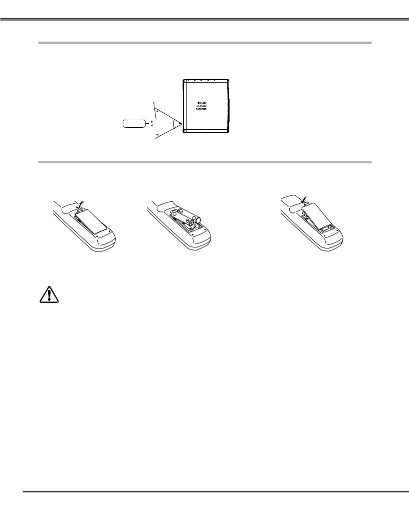
Remote Control Operating Range
Point the remote control toward the projector (Infrared Remote Receiver) when pressing any buttons. Maximum operating range for the remote control is about 16.4’ (5 m) and 60 degrees in front of the projector.
16.4’ (5 m)
 30°
30°
Remote control  30°
30°
Remote Control Battery Installation
1 |
Open the battery |
compartment lid. |
Pull up the lid and open it.
2 |
Install new batteries |
3 Replace the compartment lid. |
into the compartment. |
Two AA size batteries
For correct polarity (+ and –), be sure battery terminals are in contact with pins in the compartment.
*When the batteries of the remote control are replaced, the remote control code automatically returns to the initial code (Code 1) (p.41).
To ensure safe operation, please observe the following precautions: ● Use two (2) AA or LR6 type alkaline batteries.
● Always replace batteries in sets.
●Do not use a new battery with a used battery.
●Avoid contact with water or liquid.
●Do not expose the remote control to moisture or heat.
●Do not drop the remote control.
●If the battery has leaked on the remote control, carefully wipe the case clean and install new batteries.
●Risk of explosion if battery is replaced by an incorrect type.
●Dispose of used batteries according to the instructions.
12
Installation
Positioning the Projector
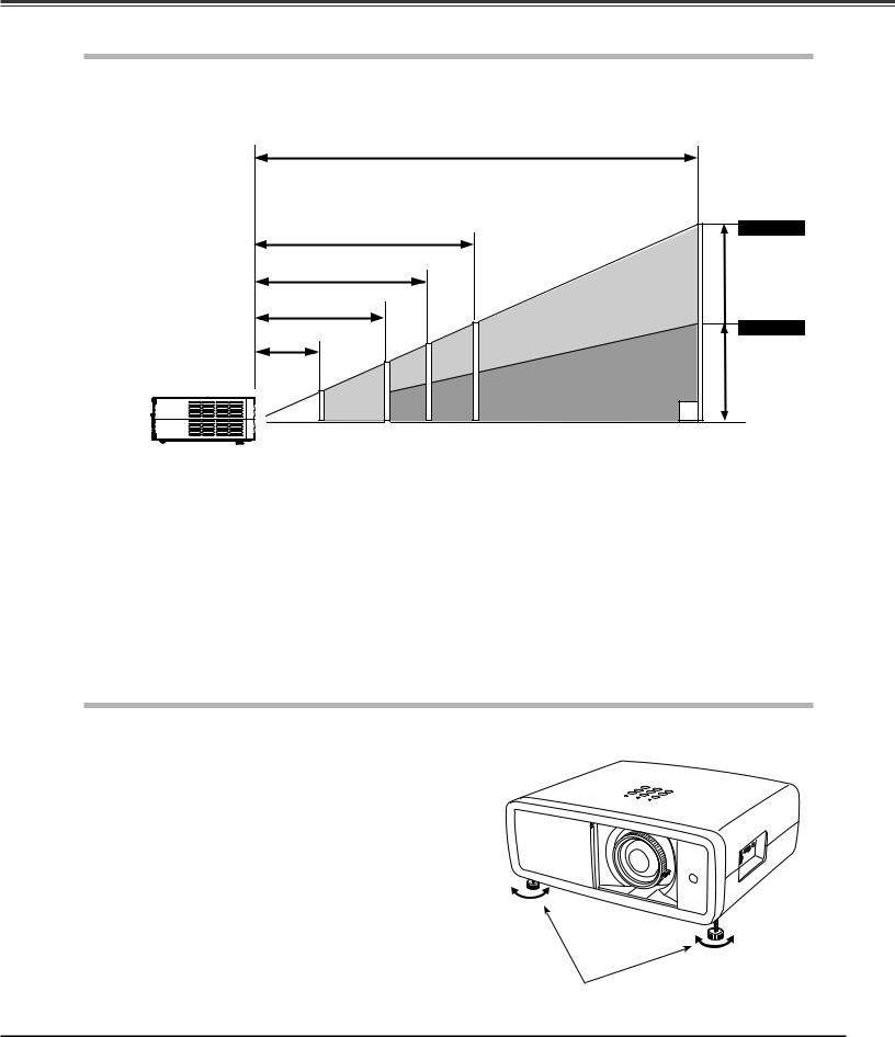
This projector is designed to project on a flat projection surface having a focus range of 3.9’ (1.2 m) to 30.2’ (9.2 m) at maximum zoom and 7.9’ (2.4 m) to 60.4’ (18.4 m) at minimum zoom. Refer to the figure and table below for the screen size and distance between the projector and screen.
|
|
|
30.2’ (9.2 m) |
|
|
|
|
|
|
300” |
(Inch Diagonal) |
|
15.1’ (4.6 m) |
|
|
|
Max.. Zoom |
|
|
|
|
|
|
9.8’ (3.0 m) |
|
|
|
|
|
7.9’ (2.4 m) |
|
150” |
150” |
|
|
|
|
|
Min.. Zoom |
||
3.9’ (1.2 m) |
|
100” |
|
|
|
|
|
|
|
||
|
80” |
|
75” |
|
|
|
|
50” |
|
|
|
40” |
40” |
|
|
|
|
|
|
|
|
||
|
|
|
|
|
(Center) |
Screen Size |
40” |
80” |
100” |
150” |
300” |
|
(W x H) mm |
|
|
|
|
|
|
886 x 498 |
1771 x 996 |
2214 x 1245 |
3321 x 1868 |
6641 x 3736 |
||
16 : 9 aspect ratio |
||||||
Zoom (max) |
3.9’ (1.2 m) |
7.9’ (2.4 m) |
9.8’ (3.0 m) |
15.1’ (4.6 m) |
30.2’ (9.2 m) |
|
|
|
|
|
|
|
|
Zoom (min) |
7.9’ (2.4 m) |
16.0’ (4.9 m) |
20.0’ (6.1 m) |
30.2’ (9.2 m) |
60.4’ (18.4 m) |
|
|
|
|
|
|
|
Note:
•The brightness in the room has a great influence on picture quality. It is recommended to limit ambient lighting in order to obtain the best image.
•All measurements are approximate and may vary from the actual sizes.
Adjustable Feet
Projection angle can be adjusted up to 6.5 degrees with the adjustable feet.
1 |
Rotate the adjustable feet and tilt the projector to the proper |
height; to raise the feet, rotate the both feet clockwise. |
|
2 |
To lower or to retract the adjustable feet, rotate the both feet |
counterclockwise. |
Adjustable Feet
13
Installation
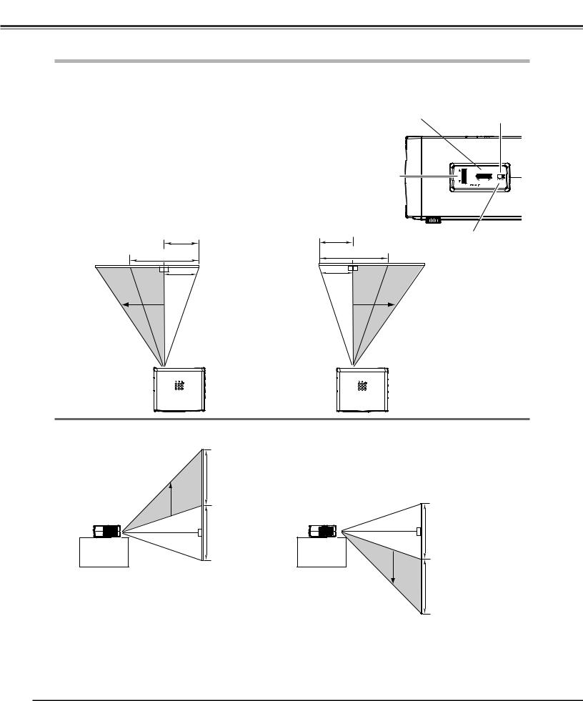
Moving the Lens
The projection lens can be moved up and down or left and right manually with the Lens Shift Rings, enabling you to adjust the position of a projected image. After adjusting the position, lock the lens with the Lens Shift Lock.
Move the projection lens to the left or right with the Horizontal Lens Shift Ring.
Move the projection lens up or down with the Vertical Lens Shift Ring.
Horizontal Lens Shift (Left/Right)
1/2W
W
Horizontal Lens Shift Ring |
Lens Shift Lock |
(Left/Right) |
|
Vertical Lens Shift Ring |
|
(Up/Down) |
|
1/2W |
|
Before using the |
|
W |
Lens Shift Rings, |
|
make sure that this |
|
|
|
|
|
|
lock is released. |
leftmost |
rightmost |
Vertical Lens Shift (Up/Down)
V
V |
V |
V
uppermost |
downmost |
Note:
•The best image is generally obtained at the central axis of the lens shift.
•With maximum lens shift in each direction, image distortion may be observed at the edge of the screen.
•With the maximum horizontal lens shift, the maximum vertical lens shift cannot be obtained, and vice versa.
•The Lens Shift Rings are locked at the factory. Make sure that the Lens Shift Lock is released before using the Lens Shift Rings.
14
Installation
This projector can be connected up to six equipment at one time. See the figures below for the connections.
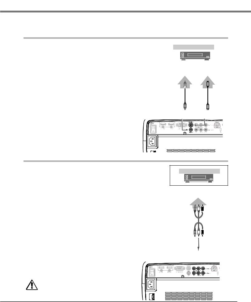
Connecting to Video Equipment (Video, S-Video)
Video, S-video |
|
|
|
|
Video Equipment |
||||
Use a video cable or a S-video cable (commercially available). |
||||
|
|
|
||
|
|
|
|
|
|
|
|
|
|
Composite |
S-VIDEO |
||||
Video Output |
Output |
||||
|
|
|
|
|
|
|
|
|
|
|
|
|
|
|
|
|
|
|
|
|
|
|
|
Video Cable |
S-video |
(RCA x 1) |
Cable |
VIDEO |
S-VIDEO |
Connecting to Video Equipment (Component)
Component |
Video Equipment |
|
Use a component cable (optional). |
||
|
Component Video Output
(Y, Pb/Cb, Pr/Cr)
Component |
Cable |
(RCA x 3) |
Note:
•To order the optional cables, see page 58.
•When connecting HDTV equipment to the projector’s COMPONENT 1/2 terminals, horizontal line noise may be noted only occasionally.Then adjust the value of Fine sync.The setting can be adjusted from 0 to +31 (see page 34).
Unplug the power cords of both the projector and external equipment from the AC outlet before connecting the cables..
COMPONENT
15
Installation
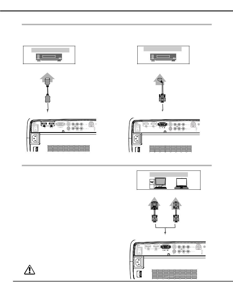
Connecting to Video Equipment (HDMI, RGB Scart)
HDMI
Use a HDMI cable (optional) for HDMI output.
Video Equipment
HDMI Video
Output
RGB Scart
Use a Scart-VGA cable (optional).
Video Equipment
RGB Scart
21-pin Output
HDMI |
Cable |
HDMI
Connecting to a Computer
Scart-VGA
Cable
COMPUTER |
Computer (Analog) |
Computer |
|
Use a VGA cable (commercially available) or a DVI-VGA cable |
||
|
||
(commercially available). |
|
|
|
Monitor Out |
DVI-VGA |
VGA |
Cable |
Cable |
Note:
• To order the optional cables, see page 58.
Unplug the power cords of both the projector and external equipment from the AC outlet before connecting the cables..
COMPUTER |
16
Installation
Connecting the AC Power Cord
This projector uses nominal input voltages of 100 – 120 V or 200
– 240 V AC and it automatically selects a correct input voltage. It is designed to work with the single-phase power systems having a grounded neutral conductor. To reduce the risk of electrical shock, do not plug into any other type of power system.
If you are not sure of the type of power being supplied, consult your authorized dealer or service station.
Connect the projector with all peripheral equipment before turning it on.
CAUTION
The AC outlet must be near this equipment and must be easily accessible.
Note:
Connect the AC power cord (supplied) to the projector.
For safety, unplug the AC power cord when the projector is not in use.
When the projector is connected to an outlet with the AC power cord and the Main On/Off switch is on, it is in stand-by mode and consumes a little electric power. Turn the Main On/ Off switch off when the projector is not in use.
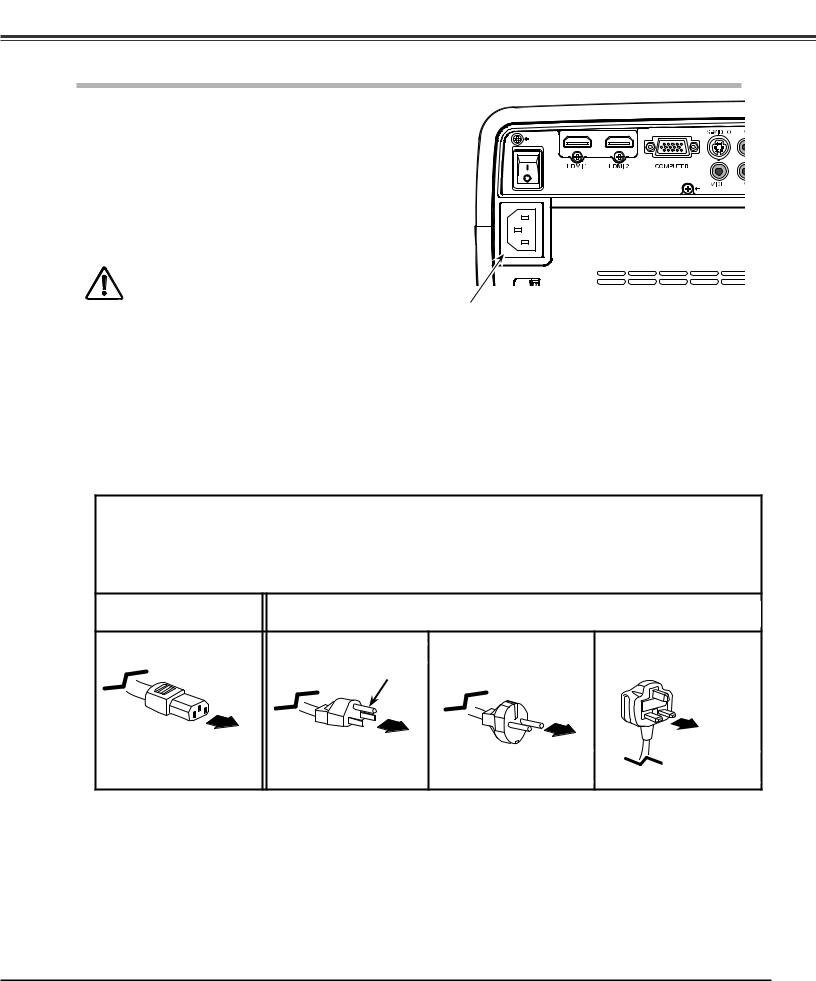
NOTE ON THE POWER CORD
AC power cord must meet the requirements of the country where you use the projector.
Confirm the AC plug type with the chart below and proper AC power cord must be used.
If the supplied AC power cord does not match your AC outlet, contact your sales dealer.
Projector side |
|
AC Outlet side |
|
|
For the U..S..A.. and Canada |
For Continental Europe |
For the U..K.. |
|
Ground |
|
|
To POWER CORD |
|
|
|
CONNECTOR on your |
To the AC Outlet. |
To the AC Outlet. |
To the AC Outlet. |
projector. |
(120 V AC) |
(200–240 V AC) |
(200–240 V AC) |
17
Basic Operation
Turning On the Projector
1 |
Complete peripheral connections (with a computer, VCR, |
etc.) before turning on the projector. |
|
2 |
Connect the projector’s AC power cord into an AC outlet and |
turn the Main On/Off switch on. The POWER indicator lights |
|
|
red. |
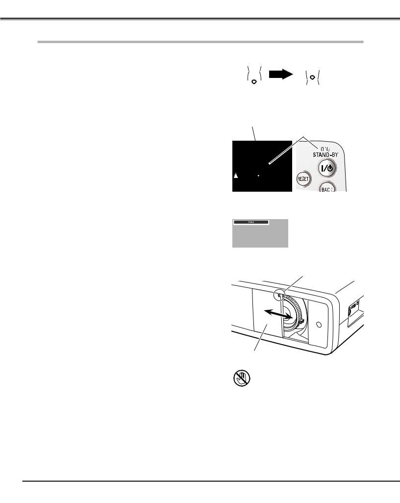
3 |
Press the POWER ON/STAND-BY button on the top control or |
on the remote control. |
|
|
The POWER indicator turns green and the cooling fans start to |
|
operate. As the automatic slide shutter opens, a preparation |
|
display appears on the screen and the countdown starts. |
4 |
After the countdown, the input source that was selected the |
last time appears on the screen. |
Main On/Off switch
OFF |
ON |
|
POWER indicator |
POWER |
|
ON/STAND-BY |
||
|
||
|
button |
Note:
•If the automatic slide shutter does not open properly, the projector will not be turned on and the POWER indicator will blink orange. Press the POWER ON/STAND-BY button again to restart.
•When “Countdown off” or “Off” is selected in the Display function, the countdown will not be displayed on the screen (p.40).
•During the countdown period, all operations are invalid.
•Image may look dark for a while after turning on the projector. Lamp needs some time to stabilize after the power is turned on. Stored lamp mode and the image mode will be active after the lamp is stabilized.
•When the shutter is manually closed slightly during projection, the shutter will be automatically closed.
Top Control |
Remote Control |
Selected Input Source
Use this tab when handling manually.
Automatic Slide Shutter
Do not touch the slide shutter while it is moving, as this could cause injury or the projector to malfunction.
18
Loading...