


PARTS MANUAL
STAY-LEVEL HANDLEBAR SERIES
MODELS
PS706016
PS706020
PS706026
PS706030
PS706036
PAVEMENT SAW
(DEUTZ BF3L2011 DIESEL ENGINE)
Revision #8 (07/26/10)
To find the latest revision of this publication, visit our website at: www.multiquip.com
THIS MANUAL MUST ACCOMPANYTHE EQUIPMENT AT ALLTIMES.
P/N 37558

PROPOSITION 65WARNING
Engine exhaust and some of its constituents, and some dust created by power sanding, sawing, grinding, drillingandotherconstructionactivities contains chemicals known to the State of California to cause cancer, birth defects and other reproductive harm. Some examples of these chemicals are:
 Leadfromlead-basedpaints.
 Crystallinesilicafrombricks.
 Cementandothermasonryproducts.
  Arsenicandchromiumfromchemically treatedlumber.
Your risk from these exposures varies, dependingonhowoftenyoudothistype of work. To reduce your exposure to these chemicals: ALWAYS work in a well ventilated area, and work with approved safety equipment, such as dust masks that are specially designed to filter out microscopic particles.
PAGE 2 — PS7060 SERIES MULTIQUIP SAW — PARTS MANUAL — REV. #8 (07/26/10)
SILICOSIS/RESPIRATORYWARNINGS
 WARNING
SILICOSIS WARNING
Grinding/cutting/drilling of masonry, concrete, metal and other materials with silica in their composition may give off dust or mists containing crystalline silica. Silica is a basic component of sand, quartz, brick clay, granite and numerous other minerals and rocks. Repeated and/or substantial inhalation of airborne crystalline silica can cause serious or fatal respiratory diseases, including silicosis. In addition, California and some other authorities have listed respirable crystalline silica as a substance known to cause cancer. When cutting such materials, always follow the respiratory precautions mentioned above.
 WARNING
RESPIRATORY HAZARDS
Grinding/cutting/drilling of masonry, concrete, metal and other materials can generate dust, mists and fumes containing chemicals known to cause serious or fatal injury or illness, such as respiratory disease, cancer, birth defects or other reproductive harm. If you are unfamiliar with the risks associated with the particular process and/or material being cut or the composition of the tool being used, review the material safety data sheet and/or consult your employer, the material manufacturer/supplier, governmental agencies such as OSHA and NIOSH and other sources on hazardous materials. California and some other authorities, for instance, have published lists of substances known to cause cancer, reproductive toxicity, or other harmful effects.
Control dust, mist and fumes at the source where possible. In this regard use good work practices and follow the recommendations of the manufacturers or suppliers, OSHA/NIOSH, and occupational and trade associations. Water should be used for dust suppression when wet cutting is feasible. When the hazards from inhalation of dust, mists and fumes cannot be eliminated, the operator and any bystanders should always wear a respirator approved by NIOSH/MSHA for the materials being used.
PS7060 SERIES MULTIQUIP SAW — PARTS MANUAL — REV. #8 (07/26/10) — PAGE 3

PS7060 SERIES SAWS
Proposition 65 Warning .................................................. |
2 |
Silicosis/Respiratory Warnings ...................................... |
3 |
Table of Contents........................................................... |
4 |
Parts Ordering Procedures ............................................ |
5 |
Explanation of Code in Remarks Column ...................... |
6 |
Suggested Spare Parts ................................................. |
7 |
Nameplates and Decals ............................................. |
8-9 |
Control Panel Decals .............................................. |
10-11 |
Electrical Control Assembly ................................... |
12-13 |
Console Mounts Assembly..................................... |
14-15 |
Rear Console Access Panel Assembly .................. |
16-17 |
Light Connector/Dash Access Assembly ............... |
18-19 |
Belt and Engine Guards Assembly......................... |
20-21 |
Depth Indicator/Stop Switch Assy. (Old Style) ....... |
22-23 |
Depth Indicator/Stop Switch Assy. (New Style) ...... |
24-25 |
F-N-R Assembly ..................................................... |
26-27 |
Fuel Assembly ....................................................... |
28-29 |
Battery Assembly ................................................... |
30-31 |
Stay-Level Handlebars Assembly .......................... |
32-33 |
Handlebar Boot Assembly ...................................... |
34-35 |
Water System Assembly ........................................ |
36-37 |
Engine Assembly ................................................... |
38-39 |
Throttle Control Assembly ...................................... |
40-41 |
Engine Mounts Assembly ...................................... |
42-43 |
Air Cleaner Assembly ............................................. |
44-45 |
Muffler Assembly ................................................... |
46-47 |
Lift Bail Assembly .................................................. |
48-49 |
Platform Guards/Rear Pointer Assembly ................ |
50-51 |
Wheel Drive Assembly ........................................... |
52-53 |
Front Axle Assembly .............................................. |
54-55 |
Hydraulic System Assembly .................................. |
56-57 |
Engine Pivot Cylinder Assembly ............................ |
58-59 |
Hydraulic Hoses Assembly .................................... |
60-61 |
Hydraulic Fttings and Clamps Assembly................ |
62-63 |
Front Pointer Assembly .......................................... |
64-65 |
Belt Drive Assembly............................................... |
66-69 |
Drive Pulley Assembly ........................................... |
70-71 |
Bladeshaft Assembly ............................................. |
72-73 |
16", 20", 26" Bladeguard Assembly ...................... |
74-75 |
30", 36" Bladeguard Assembly .............................. |
76-77 |
Optional Weight Kit Assembly ................................ |
78-79 |
Terms and Conditions of Sale — Parts........................ |
80 |
TABLE OF CONTENTS
NOTICE
Specification and part number are subject to change without notice.
PAGE 4 — PS7060 SERIES MULTIQUIP SAW — PARTS MANUAL — REV. #8 (07/26/10)
www.multiquip.com

PARTS ORDERING PROCEDURES
Ordering parts has never been easier! |
||
Choose from three easy options: |
||
|
Effective: |
|
|
January 1st, 2006 |
|
Best Deal! Order via Internet (Dealers Only): |
If you have an MQ Account, to obtain a Username |
|
Order parts on-line using Multiquip’s SmartEquip website! |
||
and Password, E-mail us at: parts@multiquip. |
||
N View Parts Diagrams |
com. |
|
N Order Parts |
To obtain an MQ Account, contact your |
|
N Print Specification Information |
District Sales Manager for more information. |
|
Goto www.multiquip.com and click on |
Use the internet and qualify for a 5% Discount |
Order Parts to log in and save! |
on Standard orders for all orders which include |
|
complete part numbers.* |
|
Note: Discounts Are Subject To Change |
|
|
|
|
Order via Fax (Dealers Only): |
|
Fax your order in and qualify for a 2% Discount |
|
|
|
|
|
|
|
|
|||
|
|
|
|
All customers are welcome to order parts via Fax. |
|
on Standard orders for all orders which include |
||
|
|
|
|
|
||||
|
|
|
|
Domestic (US) Customers dial: |
|
complete part numbers.* |
||
|
|
|
|
1-800-6-PARTS-7 (800-672-7877) |
|
|
|
|
|
Note: Discounts Are Subject To Change |
|||||||
|
|
|
|
|
||||
|
|
|
|
|
|
|||
|
|
|
|
|
|
|
|
|
Order via Phone: Domestic (US) Dealers Call:
1-800-427-1244
Non-Dealer Customers: |
|
International Customers should contact |
|||||
Contact your local Multiquip Dealer for |
|
||||||
|
their local Multiquip Representatives for |
||||||
|
|
|
|
|
|
|
|
parts or call 800-427-1244 for help in |
|
||||||
|
Parts Ordering information. |
||||||
locating a dealer near you. |
|
||||||
|
|
||||||
|
|
|
|
|
|||
When ordering parts, please supply: |
|||||||
R |
Dealer Account Number |
R Specify Preferred Method of Shipment: |
|
R |
Dealer Name and Address |
UPS/Fed Ex |
DHL |
R |
Shipping Address (if different than billing address) |
N Priority One |
Truck |
R |
Return Fax Number |
N Ground |
|
N Next Day |
|
||
R |
Applicable Model Number |
|
|
N Second/Third Day |
|
||
|
|
|
|
RQuantity, Part Number and Description of Each Part
 NOTICE
All orders are treated as Standard Orders and will ship the same day if received prior to 3PM PST.
WE ACCEPT ALL MAJOR CREDIT CARDS!
PS7060 SERIES MULTIQUIP SAW — PARTS MANUAL — REV. #8 (07/26/10) — PAGE 5

EXPLANATION OF CODE IN REMARKS COLUMN
The following section explains the different symbols and remarks used in the Parts section of this manual. Use the help numbers found on the back page of the manual if there are any questions.

 NOTICE
The contents and part numbers listed in the parts section are subject to change without notice.Multiquip does not guarantee the availability of the parts listed.
SAMPLE PARTS LIST
NO. PART NO. |
PART NAME |
QTY. |
REMARKS |
|
1 |
12345 |
BOLT...................... |
1 ..... |
INCLUDES ITEMS W/% |
2% |
|
WASHER, 1/4 IN............ |
|
NOT SOLD SEPARATELY |
2% |
12347 |
WASHER, 3/8 IN.... |
1 ..... |
MQ-45T ONLY |
312348 HOSE ..................A/R ...MAKE LOCALLY
412349 BEARING ..............1 .....S/N 2345B AND ABOVE
NO. Column
Unique Symbols — All items with same unique symbol
(@, #, +, %, or >) in the number column belong to the same assembly or kit, which is indicated by a note in the “Remarks” column.
Duplicate Item Numbers — Duplicate numbers indicate multiple part numbers, which are in effect for the same general item, such as different size saw blade guards in use or a part that has been updated on newer versions of the same machine.

 NOTICE
When ordering a part that has more than one item number listed, check the remarks column for help in determining the proper part to order.
PART NO. Column
QTY. Column
Numbers Used — Item quantity can be indicated by a number, a blank entry, or A/R.
A/R (As Required) is generally used for hoses or other parts that are sold in bulk and cut to length.
A blank entry generally indicates that the item is not sold separately.Other entries will be clarified in the “Remarks” Column.
REMARKS Column
Some of the most common notes found in the “Remarks” Column are listed below. Other additional notes needed to describe the item can also be shown.
Assembly/Kit — All items on the parts list with the same unique symbol will be included when this item is purchased.
Indicated by:
“INCLUDES ITEMS W/(unique symbol)”
Serial Number Break — Used to list an effective serial number range where a particular part is used.
Indicated by:
“S/N XXXXX AND BELOW” “S/N XXXX AND ABOVE” “S/N XXXX TO S/N XXX”
Specific Model Number Use — Indicates that the part is used only with the specific model number or model number variant listed. It can also be used to show a part is NOT used on a specific model or model number variant.
Indicated by:
“XXXXX ONLY”
“NOT USED ON XXXX”
Numbers Used — Part numbers can be indicated by a number, a blank entry, or TBD.
TBD (To Be Determined) is generally used to show a part that has not been assigned a formal part number at the time of publication.
A blank entry generally indicates that the item is not sold separately or is not sold by Multiquip. Other entries will be clarified in the “Remarks” Column.
“Make/Obtain Locally” — Indicates that the part can be purchased at any hardware shop or made out of available items. Examples include battery cables, shims, and certain washers and nuts.
“Not Sold Separately”— Indicates that an item cannot be purchased as a separate item and is either part of an assembly/kit that can be purchased, or is not available for sale through Multiquip.
PAGE 6 — PS7060 SERIES MULTIQUIP SAW — PARTS MANUAL — REV. #8 (07/26/10)

SS7060 SANDERS SAW
1 TO 3 UNITS WITH DEUTZ TURBO DIESEL ENGINE
Qty. |
P/N |
Description |
1 ....... |
37094 .................. |
SWITCH, TOGGLE F-N-R |
1 ....... |
37203 .................. |
SWITCH, ROLLER PLUNGER |
2 ....... |
406000 ................ |
SWITCH, ROCKER |
2 ....... |
37132 .................. |
FRONT WHEEL ASSEMBLY |
2 ....... |
37095 .................. |
REAR WHEEL |
1 ....... |
29509 .................. |
CAP, FUEL TANK |
2 ....... |
560017 ................ |
GRIPS, HANDLEBAR |
1 ....... |
H9406 .................. |
BULB, GE H9406 |
1 ....... |
15503 .................. |
KNOB, COMFORT |
1 ....... |
37311 .................. |
BALLVALVE, WATER SYSTEM |
2 ....... |
570005 ................ |
CLAMP, MUFFLER |
2 ....... |
37048 .................. |
SPRING, WHEEL DRIVE |
2 ....... |
582012 ................ |
BUSHING, QD |
2 ....... |
915316 ................ |
SCREW, 5/8 - 11 X 3 LH GR8 |
2 ....... |
915315 ................ |
SCREW, 5/8 - 11 X 3 GR8 |
1 ....... |
574003 ................ |
ROPE, POINTER |
1 ....... |
37212 .................. |
THROTTLE ASSEMBLY |
2 ....... |
200019 ................ |
MUDFLAP, BLADEGUARD |
FOR SAWS WITH 16", 20", AND 26" BLADEGUARDS |
||
2 ....... |
37168 .................. |
FLANGE, INNER 5.0" |
2 ....... |
37169 .................. |
FLANGE ASSEMBLY, OUTER 5.0" |
2 ....... |
926790 ................ |
PIN, DOWEL |
2 ....... |
362000 ................ |
HOSE, WATER #6LP (16" BLADEGUARD) |
2 ....... |
362005 ................ |
HOSE, WATER #6LP (20" BLADEGUARD) |
2 ....... |
362006 ................ |
HOSE, WATER #6LP (26" BLADEGUARD) |
FOR SAWS WITH 30" AND 36" BLADEGUARDS |
||
2 ....... |
37177 .................. |
FLANGE, INNER 6.0" |
2 ....... |
37176 .................. |
FLANGE ASSEMBLY, OUTER 6.0" |
2 ....... |
926790 ................ |
PIN, DOWEL |
2 ....... |
362007 ................ |
HOSE, WATER #6LP (30" BLADEGUARD) |
2 ....... |
362008 ................ |
HOSE, WATER #6LP (36" BLADEGUARD) |
NOTICE
Part numbers on this Suggested Spare Parts List may supercede/replace the P/N's shown in the text pages of this manual.
SUGGESTED SPARE PARTS
ENGINE PARTS FOR DEUTZ TURBO DIESEL ENGINE
2 ....... |
1174416 .............. |
OIL FILTER, DEUTZ BF3L2012 |
2 ....... |
304010 ................ |
FUEL FILTER, DEUTZ BF3L2011 |
2 ....... |
P772579 .............. |
PRIMARY AIR FILTER ELEMENT |
2 ....... |
P775300 .............. |
SAFETY AIR FILTER, DEUTZ BF3L2014 |
2 ....... |
21004-003 ........... |
FAN BELT, AX-35 |
2 ....... |
520007 ................ |
DRIVE BELT, 5G 3VX-530 |
1 ....... |
406017 ................ |
IGNITION SWITCH, W/KEY |
2 ....... |
406017-1 ............. |
KEY, IGNITION |
2 ....... |
306006 ................ |
FILTER, TRANSMISSION |
PS7060 SERIES MULTIQUIP SAW — PARTS MANUAL — REV. #8 (07/26/10) — PAGE 7

NAMEPLATES AND DECALS
NAMEPLATES AND DECALS
PAGE 8 — PS7060 SERIES MULTIQUIP SAW — PARTS MANUAL — REV. #8 (07/26/10)

NAMEPLATES AND DECALS
NAMEPLATES AND DECALS |
|
|
||
NO. |
PART NO. |
PART NAME |
QTY. |
REMARKS |
1 |
37362 |
DECAL, STAY LEVEL HANDLE WHITE |
2 |
|
2 |
20936 |
DECAL, MQ MULTIQUIP 5.93 X 7.45 |
2 |
|
3 |
37365 |
DECAL, MQ PS7060 |
2 |
|
4 |
|
SERIAL TAG ............................................................ |
1 .................. |
CONTACT PARTS DEPT. |
5 |
M600002 |
DECAL, DIESEL FUEL ONLY |
1 |
|
6 |
25482 |
DECAL, MQ LOGO 3.0 X 3.75 |
1 |
|
7 |
37161 |
DECAL, HOT ISO HI-TEMPERATURE .................... |
1 .................. |
SAFETY ITEM |
8 |
13118 |
DECAL, POWDER COATED |
1 |
|
9 |
20525 |
DECAL, WARNING "PROP 65" 3.25 X 4.25 ............ |
1 .................. |
SAFETY ITEM |
10 |
36092 |
DECAL, WARNING DIESEL FUEL 3.5 X 1.75 ......... |
1 .................. |
SAFETY ITEM |
11 |
36090 |
DECAL, WARNING VENTILATION 2 X 4 ................. |
1 .................. |
SAFETY ITEM |
12 |
11912 |
DECAL, PATENT PENDING |
1 |
|
13 |
25282 |
DECAL, ATTENTION BATTERY DISCONNECTED |
1 |
|
14 |
35137 |
DECAL, WARNING READ MANUAL ........................ |
1 .................. |
SAFETY ITEM |
15 |
36099 |
DECAL, PROTECTIVE CLOTHING ISO BLUE ........ |
1 .................. |
SAFETY ITEM |
16 |
37540 |
DECAL, HYDRAULIC RESERVOIR |
1 |
|
17 |
21302 |
DECAL, WARNING KEEP GUARDS IN PLACE ...... |
2 .................. |
SAFETY ITEM |
18 |
22122-001 |
DECAL, WARNING RX-W ........................................ |
2 .................. |
SAFETY ITEM |
19 |
25249-001 |
DECAL, WARNING KEEP HANDS CLEAR ............. |
2 .................. |
SAFETY ITEM |
20 |
25250-001 |
DECAL, WARNING KEEP FEET CLEAR ................ |
2 .................. |
SAFETY ITEM |
21 |
25678 |
DECAL, BLADE ROTATION CCW ............................ |
1 .................. |
SAFETY ITEM |
22 |
23330-001 |
DECAL, CAUTION BELT DRIVE |
2 |
|
23 |
606004 |
DECAL, GUARD REMOVAL ..................................... |
2 .................. |
SAFETY ITEM |
24 |
25491 |
DECAL, BLADE ROTATION CW |
1 |
|
25 |
11092 |
DECAL, CE |
1 |
|
PS7060 SERIES MULTIQUIP SAW — PARTS MANUAL — REV. #8 (07/26/10) — PAGE 9
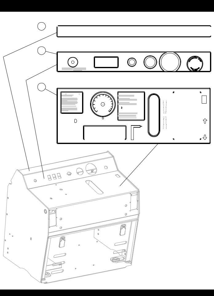
CONTROL PANEL DECALS
CONTROL PANEL DECALS
1 

2
|
ENGINE |
|
HYDRAULIC SYSTEM |
MAINTENANCE INSTRUCTIONS |
|
|
LUBRICATION |
Belt Tension: |
DRIVE BELTS |
||||||||||||||||||||||
|
|
|
|
|
|
|
|
|
|
|
|
|
|
|
|
|
|
|
|
|
Bladeshaft drive belt tension is applied hydraulically when |
|
|
|
|||||||
Air filter: |
Replace outer element when the SYSTEMS |
|
|
|
Oil Level: |
Check reservoir daily. Fill reservoir to |
|
|
|
|
|
|
|
|
Service: |
Grease every 125 hrs. of operation. |
|
|
|
||||||||||||
|
STATUS air filter restriction light comes on. |
|
|
|
|
line marked FULL COLD. |
|
|
|
|
|
|
|
|
|
Type: |
|
Use premium grade waterproof |
|
|
|
bladeshaft drive is engaged. |
|
|
|
|
|||||
|
|
|
|
|
|
|
|
|
|
|
|
|
|
|
|
To Adjust |
Perform following procedure with saw fully lowered. |
||||||||||||||
|
|
|
|
|
|
|
|
|
|
|
|
|
|
|
|
|
|
|
|
|
|
EP (extreme pressure) grease. |
|
|
|||||||
|
Replace inner element every fourth outer element. |
|
Oil type: |
15W-40 premium grade engine oil. |
|
|
|
Note: |
|
|
|
|
Drive Belt |
|
|
|
|
|
|||||||||||||
Oil: |
Check oil level daily, do not overfill. |
|
|
|
|
Oil Service: |
Change oil and filter every 500 hours of |
|
|
|
|
|
|
|
Locations: |
Front axle pivot bearings (2), lift |
|
Loosen jam nut on belt tension limiting bolt. Turn belt tension limiting bolt |
|
|
|||||||||||
|
|
|
|
|
|
|
|
|
|
|
Wheel drive propulsion system, lift pump, |
|
|
|
Tension: |
|
|
|
|
|
|||||||||||
Oil type: |
See Engine Manual. |
|
|
|
|
|
|
operation or annually, whichever occurs first. |
|
|
|
|
|
cylinder pins (2), engine tilt cylinder |
|
counterclockwise to create ½” minimum distance between end of bolt and frame. |
|
||||||||||||||
|
|
|
|
|
|
|
|
|
|
|
|
|
|
||||||||||||||||||
|
|
|
|
|
|
|
|
|
|
|
|
|
|
|
and oil bath bladeshaft share common |
|
|
|
|
|
|
|
|
|
|
Start engine and engage belt drive; increase engine speed to full throttle position for |
|||||
Oil Service: |
Change oil and filter every 125 hours |
|
|
|
|
Reservoir |
Reservoir is located inside console. Remove |
|
hydraulic oil reservoir, thus are maintained |
|
|
|
pin (1). |
|
|
|
|
||||||||||||||
|
of operation. |
|
|
|
|
|
|
Location: |
rear panel for access. |
|
|
|
|
|
|
|
|
|
|
|
|
|
|
|
|
|
15 seconds minimum. Slow engine speed to idle and shut engine off. Turn belt |
|
|||
|
|
|
|
|
|
|
|
|
|
as a single system. |
|
|
|
|
|
|
|
|
|
||||||||||||
Fuel Filter: |
Change fuel filter every 250 hours of operation. |
|
|
|
|
|
|
|
|
|
|
|
|
|
|
|
|
|
|
|
|
tension limiting bolt clockwise until bolt lightly contacts frame. Tighten locknut. |
|
||||||||
|
|
|
|
|
|
|
|
|
|
|
|
|
|
|
|
|
|
|
|
|
|
|
|
|
|
|
|
|
|
|
|
THROTTLE |
AUXILIARY |
LIGHTS |
BLADESHAFT |
IGNITION SWITCH |
BLADE SPEED |
TACHOMETER |
ENGINE WILL NOT CRANK |
|
|
OR START WHEN E-STOP |
|||||
|
ON |
ON |
DIS-ENGAGE |
|
ENGINE PRE-HEAT |
|
BUTTON IS DEPRESSED |
|
|
|
|
|
GLOW PLUG |
|
|
|
|
|
|
START |
|
|
|
|
|
|
|
ON |
|
|
|
TO INCREASE ENGINE SPEED: TURN KNOB COUNTERCLOCKWISE. |
|
|
|
ENGINE |
|
|
|
OFF |
OFF |
ENGAGE |
PRE-HEAT |
|
|
|
|
TO REDUCE ENGINE SPEED: TURN KNOB CLOCKWISE. |
OFF |
|
|
|
|||
FOR QUICK THROTTLE ACTION: DEPRESS RED BUTTON AND |
|
|
|
SYSTEMS STATUS |
|
|
|
PUSH OR PULL KNOB. |
|
|
|
|
|
|
3
DEPTH STOP CONTROL
To Control Depth of Cut with Saw
Running and Blade Mounted:
Step 1: Raise saw above desired cutting depth. Step 2: Turn depth control knob counterclockwise until saw cannot be lowered by pushing raise/lower switch forward.
Step 3: Hold raise/lower switch in the lowering position and rotate the depth control knob clockwise until desired cutting depth is achieved. The saw will repeat to the same depth until re-adjusted.
To Re-adjust for Full Cutting Depth:
Hold raise/lower switch in the lowering position and rotate the depth control knob clockwise until saw is fully lowered. Rotate depth control knob clockwise additional 1 turn.
WATER
FLOW
CONTROL
ADJUST WATER FLOW VALVE
FOR DESIRED WATER FLOW
DEPTH  INDICATOR
|
5 |
6 |
7 |
|
|
|
|
|
|
||
|
150 |
175 |
8 |
|
|
4 |
|
|
|
||
125 |
|
200 |
|
|
|
100 |
|
|
230 |
9 |
|
3 |
|
|
|
|
|
|
|
|
|
255 |
10 |
75 |
|
|
|
|
|
|
|
|
|
280 |
|
11
2
50
305
 12
12
|
|
|
330 |
|
1 |
25 |
|
|
13 |
|
|
355 |
||
|
|
|
380 |
|
|
|
|
14 |
|
|
|
0 |
|
|
|
0 |
MM |
15 |
|
INCH
TO ADJUST CUT DEPTH INDICATOR:
LOWER SAW UNTIL BLADE CONTACTS
SURFACE, ADJUST DIAL TO ZERO.
BLADESHAFT ROTATION DIS-ENGAGEMENT SYSTEM
Engine must be at idle when engaging or
dis-engaging bladeshaft drive.
To stop bladeshaft rotation:
Push rocker switch labeled BLADESHAFT forward.
Engine will tilt forward, dis-engaging the belt drive.
To start bladeshaft rotation:
Push rocker switch labeled BLADESHAFT backward.
Engine will tilt back, engaging belt drive.
 WARNING
ENGINE MUST BE SHUT OFF |
when removing or installing |
||
blade or bladeguard or performing any type of service |
|
||
to bladeshaft or any other component on machine! |
|
||
NEVER |
attempt to remove or install blade or bladeguard |
||
with engine running by dis-engaging the belt drive!
NEVER |
attempt to service any component with the |
engine running! |
|
NEVER |
leave saw unattended while engine is running! |
RAISE/LOWER
SWITCH
|
|
|
NEVER EXCEED BLADE MANUFACTURER'S RECOMMENDED RPM'S |
FWD-NEUTRAL-REV |
|
|
CONTROL |
|
|
|
|
|
|
|
|
|
|
|
|
|
|
|
OPERATING INSTRUCTIONS |
|
||||
|
|
|
BEFORE |
|
|
|
|
|
|
|
|
|
Check all fluid levels. Secure blade firmly to |
|
|||||
FORWARD |
STARTING: |
bladeshaft. Make sure all protective guards |
|
|
|
||||
|
are in place and properly mounted. Wear eye, |
|
|
|
|||||
|
|
|
|
ear protection and protective clothing. |
|
|
|
||
|
|
|
|
|
|
|
|
|
|
|
|
|
WATER |
Connect water supply to water inlet. Move |
|
|
|
||
|
|
|
SUPPLY: |
water ON/OFF CONTROL to ON position. |
|
|
|
||
|
|
|
Adjust WATER FLOW CONTROL lever to |
|
|
|
|||
|
|
|
|
|
|
|
|||
|
|
|
|
desired position. Drain watering system in |
|
|
|
||
|
|
|
|
cold weather to prevent damage due to |
|
|
|
||
|
|
|
|
freezing. |
|
|
|
||
|
|
|
|
|
|||||
|
|
|
|
|
|
|
|
|
|
|
|
|
BLADES: |
Always follow blade manufacturer's |
|
|
|
||
|
|
|
|
recommendations for blade selection, |
|
|
|
||
|
|
|
|
speed and application. |
|
|
|
||
|
|
|
|
NEVER exceed blade manufacturer's |
|
|
|
||
|
|
|
|
|
|||||
|
|
|
|
maximum rated RPM. See operator's manual |
|
|
|
||
|
|
|
|
for detailed blade mounting instructions. |
|
|
|
||
|
|
|
|
|
|
|
|
|
|
|
|
|
|
|
|
|
|
|
|
|
|
|
STARTING |
Set CONTROL HANDLE to NEUTRAL position. |
|
|
|
|
|
|
|
|
ENGINE: |
Set THROTTLE to IDLE. Turn start switch to |
|
|
|
|
|
|
|
|
|
ON position. Wait for glow plug indicator light |
|
|
|
|
|
NEUTRAL |
|
|
|||||||
|
to go out. Momentarily turn switch to start |
|
|
|
|
||||
|
|
|
|
position; release switch as soon as engine |
|
|
|
|
|
|
|
|
|
starts. Allow engine to warm up for several |
|
|
|
|
|
|
|
|
|
minutes before increasing engine speed. Use |
|
|
|
|
|
|
|
|
|
|
|||||
|
|
|
|
approved diesel fuel only. |
|
|
|
|
|
|
|
|
STOPPING |
|
|
|
|
|
|
|
|
|
|
|
|
|
|
||
|
|
|
Do not stop engine abruptly when hot! Reduce |
|
|||||
|
|
|
ENGINE: |
THROTTLE to IDLE and allow engine to run 1 |
|
|
|||
|
|
|
|
to 2 minutes before turning ignition switch off. |
|
|
|||
|
|
|
|
Damage to engine may occur if not allowed to |
|
|
|||
|
|
|
|
cool adequately. |
|
|
|||
|
|
|
|
|
|
|
|
|
|
|
|
|
|
|
|
|
|
|
|
|
|
|
FWD- |
The panel mounted handle controls |
|
|
|
||
|
|
|
NEUTRAL- |
FORWARD, NEUTRAL and REVERSE |
|
|
|
||
|
|
|
|
||||||
|
|
|
REV |
operation. Neutral position stops or holds saw |
|
|
|
||
|
|
|
in a stationary position. Incremental |
|
|
|
|||
|
|
|
CONTROL: |
movement in the FORWARD or REVERSE |
|
|
|
||
|
|
|
|
direction will increase speed proportionate |
|
|
|
||
|
|
|
|
to amount of movement. |
|
|
|
||
REVERSE |
RAISE- |
|
|
|
|
||||
RAISE-LOWER function is controlled by the |
|
|
|
|
|||||
|
|
|
LOWER |
switch mounted at the right side of the |
|
|
|
|
|
|
|
|
FUNCTION: |
CONTROL HANDLE. Push toggle switch |
|
|
|
|
|
|
|
|
|
lever forward to lower saw. Pull toggle switch |
|
|
|
|
|
|
|
|
|
lever backward to raise saw. |
|
|
|
|
|
|
|
|
|
|
|
|
|||
|
|
|
BRAKES: |
This saw is equipped with parking brakes. |
|
|
|
||
|
|
|
|
Brakes are applied automatically when engine |
|
|
|
||
|
|
|
|
is off and dis-engaged when engine is running. |
|
|
|
||
|
|
|
|
|
|
|
|
|
|
|
|
|
|
|
|
|
|
|
|
|
|
|
|
|
|
|
|
|
|
WATER PUMP
ON
OFF
ON
WATER
OFF
PAGE 10 — PS7060 SERIES MULTIQUIP SAW — PARTS MANUAL — REV. #8 (07/26/10)
CONTROL PANEL DECALS
CONTROL PANEL DECALS |
|
|
||
NO. |
PART NO. |
PART NAME |
QTY. |
REMARKS |
1 |
37361 |
DECAL, MAINTENANCE, 7000 SERIES |
1 |
|
2 |
37354 |
DECAL, INSTRUMENT PANEL, 7000 SERIES |
1 |
|
3 |
37353 |
DECAL, OPERATION CONSOLE PANEL |
1 |
|
PS7060 SERIES MULTIQUIP SAW — PARTS MANUAL — REV. #8 (07/26/10) — PAGE 11
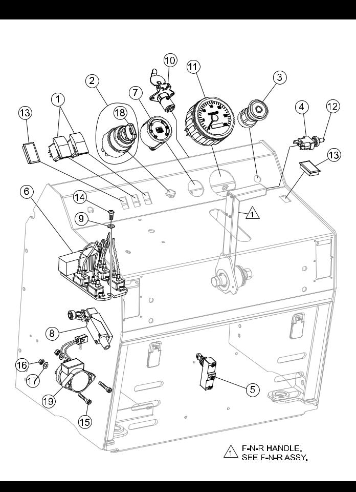
ELECTRICAL CONTROL ASSY.
ELECTRICAL CONTROL ASSY.
PAGE 12 — PS7060 SERIES MULTIQUIP SAW — PARTS MANUAL — REV. #8 (07/26/10)

ELECTRICAL CONTROL ASSY.
ELECTRICAL CONTROL ASSY. |
|
|
||
NO. |
PART NO. |
PART NAME |
QTY. |
REMARKS |
1 |
406000 |
SWITCH, ROCKER CH# M-58031-01 |
2 |
|
2 |
406017 |
IGNITION SWITCH, WITH KEYS ............................ |
1................... |
INCLUDES ITEMS W/* |
3 |
37198 |
EMERGENCY STOP SWITCH ................................ |
1 .................. |
SAFETY ITEM |
4 |
37094 |
SWITCH, TOGGLE SPDT MOMENTARY ON-ON |
1 |
|
5 |
37203 |
SWITCH, SNAP ACTION ROLLER PLUNGER |
1 |
|
6 |
37490 |
HARNESS, RELAYS AND CIRCUIT BREAKERS |
1 |
|
7 |
406021 |
INDICATOR, ENGINE |
1 |
|
8 |
37243 |
SWITCH, ROLLER ARM |
1 |
|
9 |
933240 |
WASHER, FLAT SAE 1/4 GRD 9 YZ |
3 |
|
10 |
405000 |
CONNECTOR, 4-WAY SOCKET |
1 |
|
11 |
37368 |
TACHOMETER, ELECTRIC 0-3000 RPM |
1 |
|
12 |
8381 |
BOOT,TOGGLE SWITCH |
1 |
|
13 |
406020 |
BLANK, ROCKER SWITCH |
2 |
|
14 |
973752 |
SCREW, BHHC 1/4 - 20 X 5/8 SS |
3 |
|
15 |
37325 |
SCREW, SHC M5 - 0.8 X 30MM |
2 |
|
16 |
37324 |
NUT, NYLOC M5 - 0.8 |
2 |
|
17 |
28922-058 |
WASHER, M5 |
2 |
|
18* |
406017-1 |
KEY, IGNITION |
1 |
|
19 |
25628 |
SOLENOID, LIFT PUMP |
1 |
|
PS7060 SERIES MULTIQUIP SAW — PARTS MANUAL — REV. #8 (07/26/10) — PAGE 13
CONSOLE MOUNTS ASSY.
CONSOLE MOUNTS ASSY.
PAGE 14 — PS7060 SERIES MULTIQUIP SAW — PARTS MANUAL — REV. #8 (07/26/10)

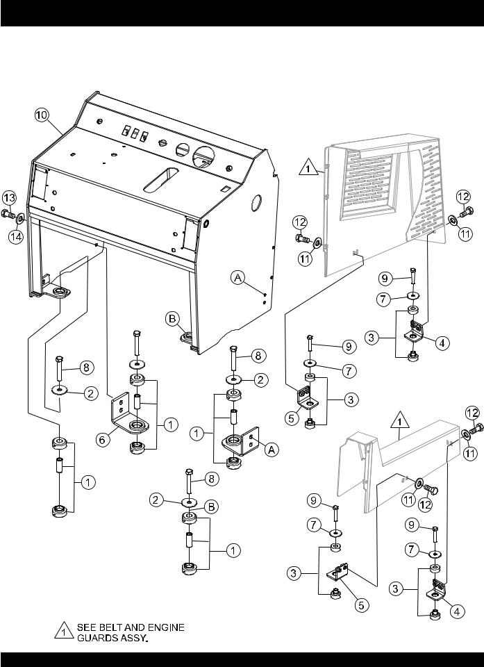
CONSOLE MOUNTS ASSY.
CONSOLE MOUNTS ASSY. |
|
|
||
NO. |
PART NO. |
PART NAME |
QTY. |
REMARKS |
1 |
20742 |
ISOLATOR, RB2 RING/BUSHING |
4 |
|
2 |
20743 |
WASHER, ISO SNUB KROFUND DYN 148099-18 |
4 |
|
3 |
575001 |
RUBBER ISOLATOR, TPC# 60166-1 |
4 |
|
4 |
37231-753 |
MOUNT, ISOLATOR FRONT |
2 |
|
5 |
37233-753 |
MOUNT, ISOLATOR SIDE |
2 |
|
6 |
37227-753 |
MOUNT, CONSOLE ISOLATOR FRONT |
2 |
|
7 |
12832 |
WASHER, SNUBBING |
4 |
|
8 |
06503-026 |
SCREW, HHC 1/2 - 13 X 3-1/4 |
4 |
|
9 |
1665 |
SCREW, HHC 3/8 - 16 X 2 |
4 |
|
10 |
37116-753 |
CONSOLE W/A |
1 |
|
11 |
933242 |
WASHER, FLAT SAE 3/9 GRD 9 Y |
8 |
|
12 |
0205 |
SCREW, HHC 3/8-16 X 1 |
8 |
|
13 |
TBD |
SCREW |
4 |
|
14 |
TBD |
WASHER |
4 |
|
PS7060 SERIES MULTIQUIP SAW — PARTS MANUAL — REV. #8 (07/26/10) — PAGE 15
REAR CONSOLE ACCESS PANEL ASSY.
5
8
6
1
2
4
7
3
9
PAGE 16 — PS7060 SERIES MULTIQUIP SAW — PARTS MANUAL — REV. #8 (07/26/10)

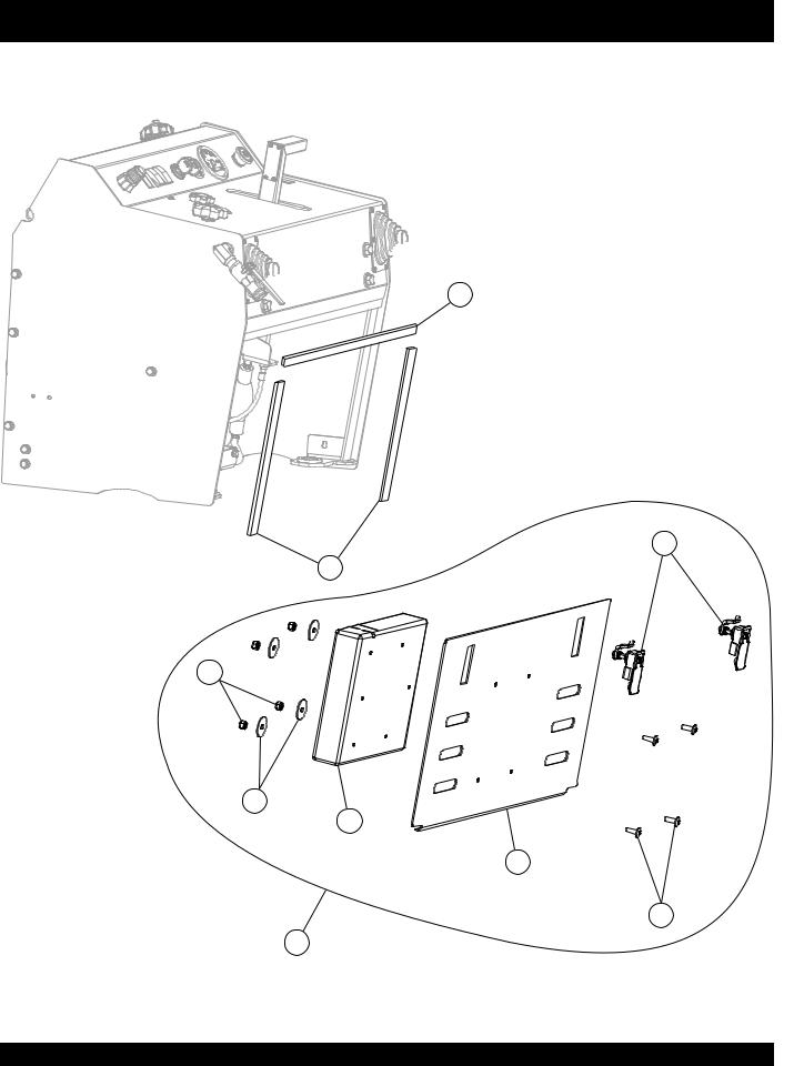
REAR CONSOLE ACCESS PANEL ASSY.
REAR CONSOLE ACCESS PANEL ASSY. |
|
|
||
NO. |
PART NO. |
PART NAME |
QTY. |
REMARKS |
1* |
10024 |
NUT, NYLOC 1/4 X 20 |
4 |
|
2* |
10930 |
WASHER, FENDER 1/4 X 1-1/4 |
4 |
|
3* |
12287 |
SCREW, THP 1/4 - 20 X 3/4 SS |
4 |
|
4* |
29057 |
DOCUMENT BOX |
1 |
|
5 |
37219 |
STRIP, BACKING PLATE SAW CONSOLE |
1 |
|
6 |
37220 |
STRIP, VERTICAL SAW CONSOLE |
2 |
|
7* |
37254-753 |
PANEL, REAR SAW ACCESS |
1 |
|
8* |
560020 |
LATCH, REAR SAW ACCESS PANEL |
2 |
|
9 |
37253 |
PANEL ASSEMBLY, REAR SAW ACCESS ............. 1 .................. INCLUDES ITEMS W/* |
||
PS7060 SERIES MULTIQUIP SAW — PARTS MANUAL — REV. #8 (07/26/10) — PAGE 17
LIGHT CONNECTOR/DASH ACCESS ASSY.
LIGHT CONNECTOR/DASH ACCESS ASSY.
PAGE 18 — PS7060 SERIES MULTIQUIP SAW — PARTS MANUAL — REV. #8 (07/26/10)

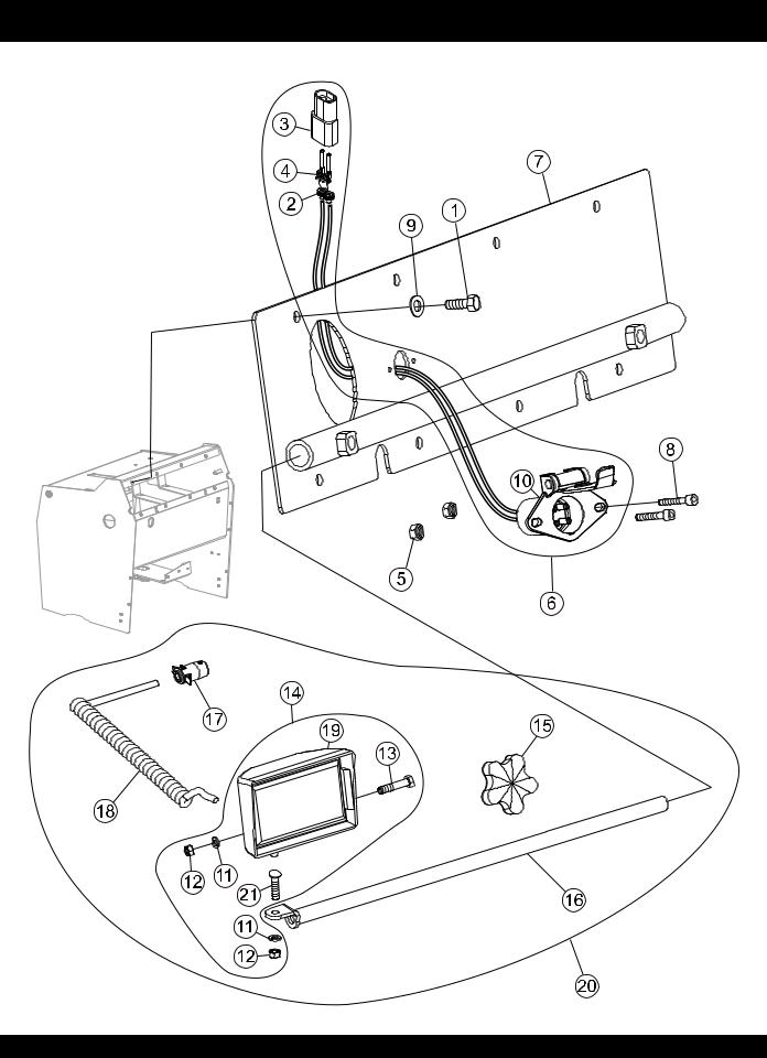
LIGHT CONNECTOR/DASH ACCESS ASSY.
LIGHT CONNECTOR/DASH ACCESS ASSY. |
|
|
||
NO. |
PART NO. |
PART NAME |
QTY. |
REMARKS |
1 |
0655 |
SCREW, HHC 5/16 - 18 X 3/4 |
8 |
|
2* |
12171 |
SEAL, WEATHERPACK 16-18 GA,GREEN |
2 |
|
3* |
12176 |
CONNECTOR, WEATHERPACK 2 PIN MALE |
1 |
|
4* |
12179 |
TERMINAL, WEATHERPACK MALE 14-16 GA |
2 |
|
5 |
13287 |
NUT, NYLOC 8-32 |
2 |
INCLUDES ITEMS W/* |
6 |
25865 |
HARNESS, LIGHT KIT ............................................ |
1 .................. |
|
7 |
37234-753 |
COVER W/A, CONSOLE DASH ACCESS |
1 |
|
8 |
923114 |
SCREW, SHC 8-32 X 1/2 |
2 |
|
9 |
933241 |
WASHER, FLAT SAE 5/16 GRD 9YZ |
8 |
|
10* |
405000 |
CONNECTOR, 4-WAY SOCKET CHROME |
1 |
|
11+# |
0161 C |
WASHER, LOCK 5/16 MED |
2 |
|
12+# |
0161 D |
NUT, HEX 5/16 - 18 |
2 |
|
13+# |
0300 A |
SCREW, HHC 5/16 - 18 X 2 |
1 |
|
14+ |
2532 |
LIGHT ASSEMBLY .................................................. |
1 .................. |
INCLUDES ITEMS W/# |
15+ |
15503 |
KNOB, COMFORT GRIP STAR |
1 |
|
16+ |
120206 |
LIGHT BAR |
1 |
|
17+ |
405001 |
CONNECTOR PLUG, 4-PIN FEMALE |
1 |
|
18+ |
405002 |
CORD, LIGHT EXTENDABLE |
1 |
|
19+# |
H9406 |
BULB, GE H9406 |
1 |
|
20 |
M18004 |
LIGHT KIT, SAW ...................................................... |
1 .................. |
INCLUDES ITEMS W/+ |
21# |
11963 |
BOLT, CARRIAGE 5/16 - 18 X 1 |
1 |
|
PS7060 SERIES MULTIQUIP SAW — PARTS MANUAL — REV. #8 (07/26/10) — PAGE 19
BELT AND ENGINE GUARDS ASSY.
PAGE 20 — PS7060 SERIES MULTIQUIP SAW — PARTS MANUAL — REV. #8 (07/26/10)
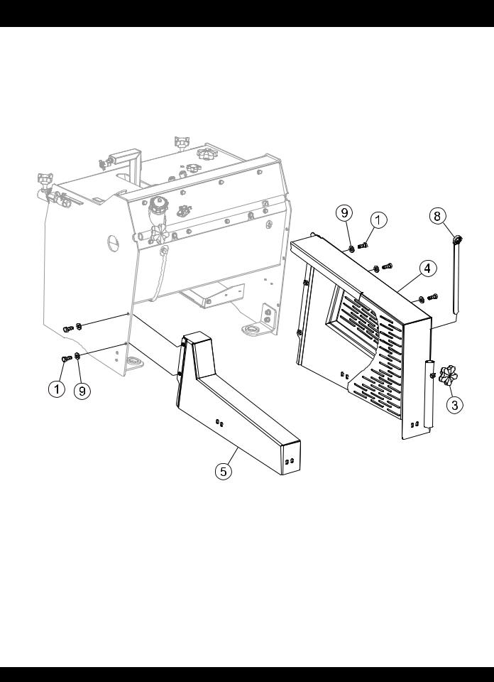
BELT AND ENGINE GUARDS ASSY.
BELT AND ENGINE GUARDS ASSY. |
|
|
||
NO. |
PART NO. |
PART NAME |
QTY. |
REMARKS |
1 |
0166 |
SCREW, HHC 3/8 - 16 X 7/8 |
5 |
|
3 |
15503 |
KNOB, COMFORT |
1 |
|
4 |
37202-753 |
GUARD, BELT DRIVE .............................................. |
1 .................. |
SAFETY ITEM |
5 |
37209-753 |
GUARD, ENGINE ..................................................... |
1 .................. |
SAFETY ITEM |
8 |
584011 |
WRENCH, 15/16 BLADE CLOSED END |
1 |
|
9 |
933242 |
WASHER, FLAT SAE 3/8 GRD 9 YZ |
5 |
|
PS7060 SERIES MULTIQUIP SAW — PARTS MANUAL — REV. #8 (07/26/10) — PAGE 21
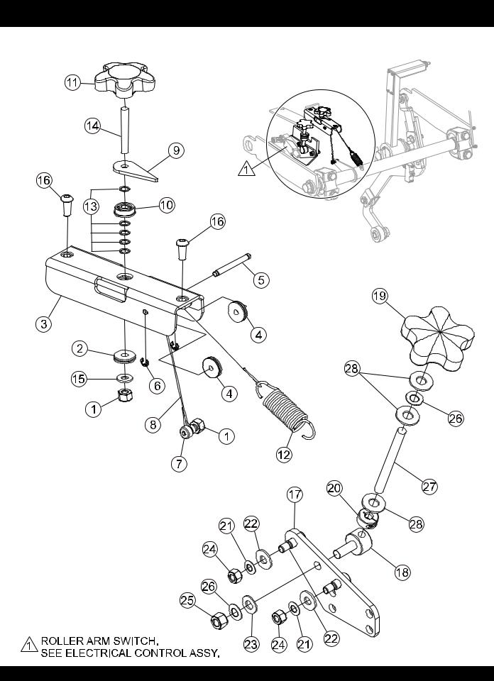
DEPTH INDICATOR/STOP SWITCH ASSY. (OLD STYLE)
DEPTH INDICATOR/STOP SWITCH ASSY. (OLD STYLE)
PAGE 22 — PS7060 SERIES MULTIQUIP SAW — PARTS MANUAL — REV. #8 (07/26/10)

DEPTH INDICATOR/STOP SWITCH ASSY. (OLD STYLE)
DEPTH INDICATOR/STOP SWITCH ASSY. (OLD STYLE) |
|
|
||
NO. |
PART NO. |
PART NAME |
QTY. |
REMARKS |
1 |
10024 |
NUT, NYLOC 1/4 - 20 |
2 |
|
2 |
37155 |
PULLEY, CABLE .75 OD |
1 |
|
3 |
37235 |
BASE, SAW DEPTH INDICATOR |
1 |
|
4 |
37240 |
PULLEY, CABLE .75 OD |
2 |
|
5 |
37241 |
SHAFT, DEPTH INDICATOR |
1 |
|
6 |
37332 |
RING, 3/16 E-STYLE EXTERNAL |
2 |
|
7 |
37401 |
SCREW, SH SHLDR 1/2-20, 5/16 OD X 1/4 L |
1 |
|
8 |
37504 |
CABLE, NYLON COAT SS .049 |
1 |
|
9 |
110031 |
POINTER, CONCRETE SAW DEPTH |
1 |
|
10 |
460019 |
FLANGE, BEARING 0.25 ID X 0.75 OD |
1 |
|
11 |
560025 |
KNOB, SAW DEPTH INDICATOR |
1 |
|
12 |
565005 |
SPRING, EXTENSION |
1 |
|
13 |
583059 |
SHIM, 0.375 OD X 0.25 ID X .020 THK |
5 |
|
14 |
584025 |
STUD, 1/4 - 20 X 1-3/4 NO PLT |
1 |
|
15 |
933240 |
WASHER, FLAT SAE 1/4 GRD 9 YZ |
1 |
|
16 |
973752 |
SCREW, BHSC 1/4 - 20 X 5/8 SS |
2 |
|
17 |
37248 |
MOUNT, SWITCH PIVOT PLATE |
1 |
|
18 |
37246 |
NUT, SWIVEL DEPTH STOP |
1 |
|
19 |
37247 |
KNOB, DEPTH STOP CONTROL |
1 |
|
20 |
37249 |
COLLAR, SHAFT THREADED 3/8 - 16 |
1 |
|
21 |
37250 |
WASHER, BELLEVIEW .317 X .625 |
2 |
|
22 |
19470 |
WASHER, FLAT 5/16 USS |
2 |
|
23 |
933242 |
WASHER, FLAT SAE 3/8 GRD 9 YZ |
1 |
|
24 |
5283 |
NUT, NYLOC 5/16 - 18 |
2 |
|
25 |
10133 |
NUT, NYLOC 3/8 - 16 |
1 |
|
26 |
37251 |
WASHER, BELLEVIEW .389 X .750 |
2 |
|
27 |
37375 |
STUD, 3/8 - 16 X 4 |
1 |
|
28 |
4001 |
WASHER, FLAT USS 3/8 PLD |
3 |
|
NOTICE
Parts on this page are no longer available. See Depth
Indicator/Stop Switch Assy. (New Style).
PS7060 SERIES MULTIQUIP SAW — PARTS MANUAL — REV. #8 (07/26/10) — PAGE 23
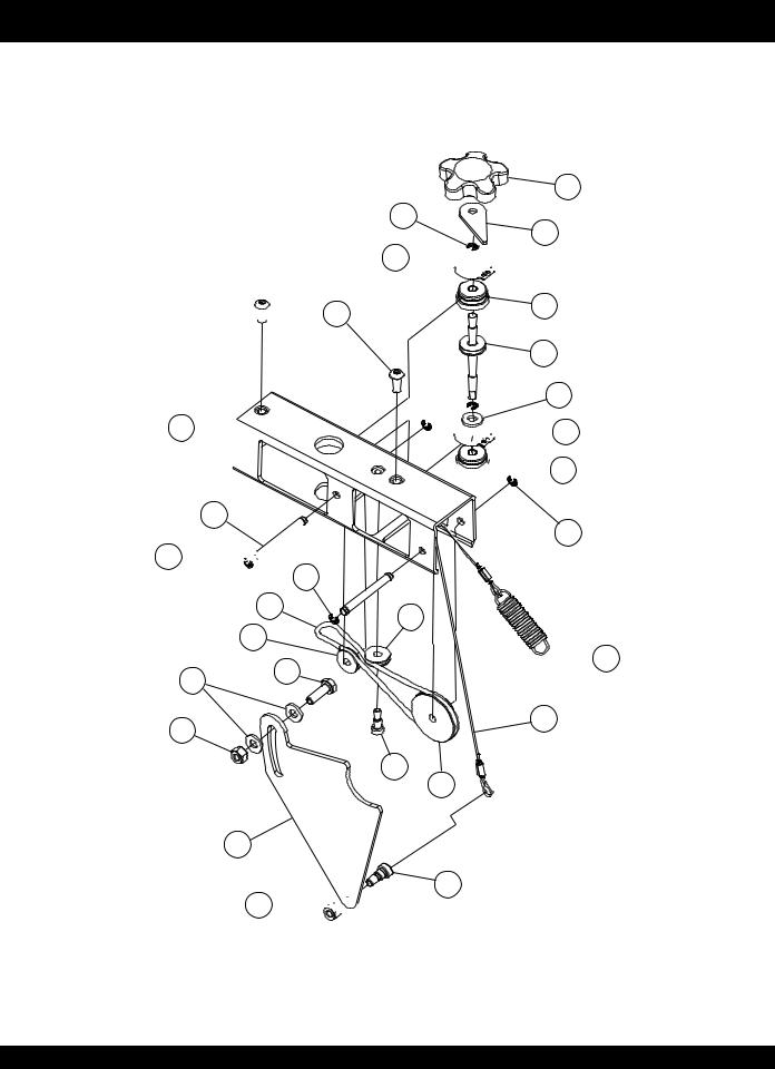
DEPTH INDICATOR/STOP SWITCH ASSY. (NEW STYLE)
DEPTH INDICATOR/STOP SWITCH ASSY. (NEW STYLE)
6
10
5
19


 13
13
14 
3
10 


 10
10
8
4
9 16
17
15
17 


2
1
9


 19
19 
 2
2
10
4
 12
12
20
11
7
18
PAGE 24 — PS7060 SERIES MULTIQUIP SAW — PARTS MANUAL — REV. #8 (07/26/10)

DEPTH INDICATOR/STOP SWITCH ASSY. (NEW STYLE)
DEPTH INDICATOR/STOP SWITCH ASSY. (NEW STYLE) |
|
|
||
NO. |
PART NO. |
PART NAME |
QTY. |
REMARKS |
1 |
37544 |
SHAFT, DEPTH INDICATOR |
1 |
|
2 |
37545 |
BUSHING, FLANGED |
2 |
|
3 |
37547 |
SHAFT, IDLER PULLEY |
2 |
|
4 |
37548 |
PULLEY, IDLER |
2 |
|
5 |
110031 |
POINTER, CONCRETE SAW DEPTH |
1 |
|
6 |
560025 |
KNOB, SAW DEPTH INDICATOR |
1 |
|
7 |
37549 |
PULLEY, DUAL GROOVE |
1 |
|
8 |
37550 |
BELT, INDICATOR DRIVE |
1 |
|
9 |
0948 |
WASHER, FLAT SAE 1/4 |
3 |
|
10 |
37332 |
RING, 3/16 E-STYLE EXTERNAL |
6 |
|
11 |
926149 |
SCREW, SHDLR 1/4D X 5/16L, 10-24 SCKT HD |
1 |
|
12 |
37162 |
SPRING, EXTENSION |
1 |
|
13 |
973752 |
SCREW, BHSC 1/4 - 20 X 5/8 SS |
2 |
|
14 |
37551 |
HOUSING, DEPTH INDICATOR |
1 |
|
15 |
37557 |
BRACKET, CABLE INDICATOR |
1 |
|
16 |
2295 |
SCREW, HHC 1/4 - 20 X 7/8 |
1 |
|
17 |
10024 |
NUT, NYLOC 1/4 - 20 |
2 |
|
18 |
37401 |
SCREW, SH SHLDR 1/2-20, 5/16 OD X 1/4 L |
1 |
|
19 |
37679 |
RING, SNAP SH 87 |
2 |
|
20 |
37678 |
CABLE ASSY., DEPTH INDICATOR |
1 |
|
NOTICE
Parts on this page replace those listed on Depth
Indicator/Stop Switch Assy. (Old Style).
PS7060 SERIES MULTIQUIP SAW — PARTS MANUAL — REV. #8 (07/26/10) — PAGE 25
 Loading...