


OPERATION AND PARTS MANUAL
®
MODEL DCA25SSIU
WHISPERWATT™ GENERATOR
(Standard)
Revision #7 (04/18/12)
To find the latest revision of this publication, visit our website at: www.mqpower.com
THIS MANUAL MUST ACCOMPANYTHE EQUIPMENT AT ALLTIMES.

PAGE 2 — DCA-25SSIU — PARTS AND OPERATION MANUAL(STD) — REV. #7 (04/18//12)

PAGE 3 — DCA-25SSIU — PARTS AND OPERATION MANUAL (STD) — REV. #7 (04/18/12)

Table Of Contents ....................................................... |
4 |
Parts Ordering Procedures ......................................... |
5 |
Rules for Safe Operation ......................................... |
6-9 |
Towing and Transportation ........................................ |
10 |
Trailer Safety Guidelines ...................................... |
11-15 |
Trailer Wiring Diagram ............................................... |
16 |
Operation Decals ................................................. |
17-18 |
DCA-25SSIU Specifications ..................................... |
19 |
General Information .................................................. |
20 |
Major Components ................................................... |
21 |
Dimensions............................................................... |
22 |
Control Panel Descriptions .................................. |
24-25 |
Engine Operating Panel Descriptions .................. |
26-27 |
Output Terminal Panel Descriptions ..................... |
28-29 |
Output Amerage Setup ........................................ |
30-31 |
Output Voltage Setup........................................... |
32-35 |
Installation ........................................................... |
36-37 |
Pre Setup ............................................................ |
38-41 |
Load Application ....................................................... |
42 |
Generator Start-up Procedure ............................. |
43-45 |
Generator Shutdown Procedure ................................ |
46 |
Maintenance ........................................................ |
47-48 |
Generator Wiring Diagram ......................................... |
50 |
Engine Wiring Diagram ............................................. |
51 |
EngineTroubleshooting ........................................ |
52-53 |
Generator/EngineTroubleshooting ............................ |
54 |
Explanation of Codes in Remarks Column ............... |
56 |
Suggested Spare Parts ............................................ |
57 |
TABLE OF CONTENTS
ISUZU C240 ENGINE
Cylinder Head and Cover Assembly .................... |
86-87 |
Cylinder Block Assembly .................................... |
88-89 |
Timing Gear Assembly ........................................ |
90-91 |
Flywheel Housing Assembly ............................... |
92-93 |
Oil Pan Assembly ................................................ |
94-95 |
Oil Pump Assembly ............................................ |
96-97 |
Crankshaft, Bridge and Flywheel Assembly ........ |
98-99 |
Oil and Fuel Filter Assembly ........................... |
100-101 |
Oil Pipe Assembly ........................................... |
102-103 |
Water Pump and Fan Assembly ...................... |
104-105 |
Intake and Exhaust Manifold Assembly .......... |
106-107 |
Air Cleaner Assembly ...................................... |
108-109 |
Engine Foot Assembly .................................... |
110-111 |
Injection Pump Assembly ............................... |
112-113 |
Electrical Parts Assembly ............................... |
114-115 |
Accessories .................................................... |
116-117 |
Injection Pump Comp. Assembly .................... |
118-121 |
Governor Comp. Assembly.............................. |
122-127 |
Feed Pump Comp. Assembly .......................... |
128-129 |
Auto Timer Assembly ...................................... |
130-131 |
Nozzle Holder Comp. Assembly ...................... |
132-133 |
Starter Comp. Assembly ................................. |
134-135 |
Alternator Comp. Assembly ............................. |
136-139 |
Terms and Conditions of Sales .............................. |
140 |
MQ POWER DCA-25SSIU AC GENERATOR
Generator Assembly ............................................ |
58-59 |
Control Box Assembly ......................................... |
60-61 |
Engine & Radiator Assembly............................... |
62-67 |
Engine Operating Panel Assembly ...................... |
68-69 |
Output Terminal Assembly ................................... |
70-71 |
Battery Assembly ................................................ |
72-73 |
Muffler Assembly ................................................ |
74-75 |
Fuel Tank Assembly ............................................ |
76-77 |
Enclosure Assembly ........................................... |
78-81 |
Rubber Seal Assembly ........................................ |
82-83 |
Name Plate And Decals ...................................... |
84-85 |
NOTE
Specification and part number are subject to change without notice.
PAGE 4 — DCA-25SSIU — PARTS AND OPERATION MANUAL(STD) — REV. #7 (04/18//12)
www.multiquip.com

PARTS ORDERING PROCEDURES
|
|
|
|
|
|
Ordering parts has never been easier! |
||||||||
|
|
|
|
|
|
|
Choose from three easy options: |
|||||||
|
|
|
|
|
|
|
|
|
|
|
|
Effective: |
||
|
|
|
|
|
|
|
|
|
|
|
|
January 1st, 2006 |
||
Best Deal! Order via Internet (Dealers Only): |
|
|
If you have an MQ Account, to obtain a Username |
|||||||||||
|
|
|
Order parts on-line using Multiquip’s SmartEquip website! |
|
|
|||||||||
|
|
|
|
|
and Password, E-mail us at: parts@multiquip. |
|||||||||
|
|
|
|
■ View Parts Diagrams |
|
|
com. |
|||||||
|
|
|
|
■ Order Parts |
|
|
To obtain an MQ Account, contact your |
|||||||
|
|
|
|
■ Print Specification Information |
|
|
District Sales Manager for more information. |
|||||||
|
|
|
|
|
|
|
|
|
|
|
||||
|
|
|
|
|
Goto www.multiquip.com and click on |
|
|
Use the internet and qualify for a 5% Discount |
|
|||||
|
|
|
|
|
|
|
|
|||||||
|
|
|
|
|
|
|
|
|
|
|
|
on Standard orders for all orders which include |
||
|
|
|
|
|
|
Order |
Parts |
to log in and save! |
||||||
|
|
|
|
|
|
|
|
|
|
|
|
complete part numbers.* |
||
|
|
|
|
|
|
|
|
|
|
|||||
|
|
|
|
|
|
|
|
|
|
|
|
|
|
|
|
|
|
|
|
|
|
|
|
|
|
|
Note: Discounts Are Subject To Change |
||
|
|
|
|
|
|
|
|
|
||||||
|
|
|
|
|
|
Order via Fax (Dealers Only): |
|
|
|
|
|
|
||
|
|
|
|
|
|
|
|
Fax your order in and qualify for a 2% Discount |
|
|||||
|
|
|
|
|
|
All customers are welcome to order parts via Fax. |
|
on Standard orders for all orders which include |
||||||
|
|
|
|
|
|
|
||||||||
|
|
|
|
|
|
Domestic (US) Customers dial: |
|
complete part numbers.* |
||||||
|
|
|
|
|
|
1-800-6-PARTS-7 (800-672-7877) |
|
|
|
|
|
|
||
|
|
|
|
|
|
|
|
|
Note: Discounts Are Subject To Change |
|||||
|
|
|
|
|
|
|
|
|
||||||
|
|
|
|
|
|
|
|
|
|
|
|
|||
|
|
|
|
|
|
|
|
|
|
|
|
|
|
|
|
|
|
|
|
|
|
Order via Phone: Domestic (US) Dealers Call: |
|||||||||||
|
|
|
|
|
|
|||||||||||||
|
|
|
|
|
|
|
|
|
|
|
|
|
1-800-427-1244 |
|
|
|||
|
|
|
|
|
|
|
|
|
|
|
|
|
|
|
|
|
|
|
|
|
|
|
|
|
|
|
|
|
|
|
|
|
|
|
|
|
|
|
|
|
Non-Dealer Customers: |
|
|
|
|
|
|
|
|
|
|
|||||
|
|
|
|
|
|
International Customers should contact |
||||||||||||
|
|
|
Contact your local Multiquip Dealer for |
|
|
|
||||||||||||
|
|
|
|
|
|
their local Multiquip Representatives for |
||||||||||||
|
|
|
parts or call 800-427-1244 for help in |
|
|
|
||||||||||||
|
|
|
|
|
|
|||||||||||||
|
|
|
|
|
|
Parts Ordering information. |
||||||||||||
|
|
|
locating a dealer near you. |
|
|
|
||||||||||||
|
|
|
|
|
|
|
|
|
||||||||||
|
|
|
|
|
|
|
|
|
|
|
|
|
|
|
|
|||
|
|
|
When ordering parts, please supply: |
|||||||||||||||
|
Dealer Account Number |
Specify Preferred Method of Shipment: |
|
|
Dealer Name and Address |
UPS/Fed Ex |
DHL |
|
Shipping Address (if different than billing address) |
Priority One |
Truck |
|
Return Fax Number |
Ground |
|
Next Day |
|
||
|
Applicable Model Number |
|
|
Second/Third Day |
|
||
|
|
|
|
Quantity, Part Number and Description of Each Part
 NOTICE
All orders are treated as Standard Orders and will ship the same day if received prior to 3PM PST.
WE ACCEPT ALL MAJOR CREDIT CARDS!
PAGE 5 — DCA-25SSIU — PARTS AND OPERATION MANUAL (STD) — REV. #7 (04/18/12)

CAUTION:
Failure to follow instructions in this manual may lead to serious injury or even death! This equipment is to be operated by trained and qualified personnel only!This equipment is for industrial use only.
The following safety guidelines should always be used when operating the DCA-25SSIU portable generator:
GENERAL SAFETY
■DONOToperateorservicethisequipmentbefore readingthisentiremanual.
■This equipment should not be operated by persons under 18 years of age.
■NEVER operate this equipment without proper protective clothing, shatterproof glasses, steeltoed boots and other protective devices required by the job.
■NEVERoperatethisequipmentwhennotfeeling well due to fatigue, illness or taking medicine.
■NEVER operate this equipment under the influence or drugs or alcohol.
■NEVER use accessories or attachments, which are not recommended by MQ Power for this equipment. Damage to the equipment and/or injury to user may result.
■Manufacturer does not assume responsibility for any accident due to equipment modifications.
■Whenever necessary, replace nameplate, operation and safety decals when they become difficult read.
■Always check the machine for loosened threads or bolts before starting.
RULES FOR SAFE OPERATION
■NEVER touch the hot exhaust manifold, muffler or cylinder. Allow these parts to cool before servicing engine or generator.
■High Temperatures – Allow the engine to cool before adding fuel or performing service and maintenance functions. Contact with hot components can cause serious burns.
■The engine of this generator requires an adequate free flow of cooling air. Never operate the generator in any enclosed or narrow area where free flow of the air is restricted.
If the air flow is restricted it will cause serious damage to the
generator or engine and may cause injury to people. The generator engine gives off DEADLY carbon monoxide gas.
CAUTION:
■Always refuel in a well-ventilated area, away from sparks and open flames.
■Always use extreme caution when working with flammable liquids. When refueling, stop the engine and allow it to cool. DO NOT smoke around or near the machine. Fire or explosion could result from fuel vapors, or if fuel is spilled on a hot engine.
■NEVER operate the generator in an explosive atmosphere or near combustible materials. An explosion or fire could result causing severe bodily harm or even death.
■Topping-off to filler port is dangerous, as it tends to spill fuel.
PAGE 6 — DCA-25SSIU — PARTS AND OPERATION MANUAL(STD) — REV. #7 (04/18//12)

RULES FOR SAFE OPERATION
CAUTION:
■NEVER touch output terminals during operation. This is extremely dangerous. Always stop the machine when contact with the output terminals is required.
CAUTION:
■Backfeed to a utility system can cause electrocution and/or property damage. Do not connect to any building's electrical system except through an approved device or after building main switch is opened.
CAUTION:
CAUTION:
DO NOT touch or open any of the below mentioned components while the generator is running. Always allow sufficient time for the engine and generator to cool before performing maintenance.
Fluid Plugs
1.Radiator Cap - Removing the radiator cap while the engine is hot, will result in high pressurized, boiling water to spew out of the radiator, causing severe scalding to any persons in the general area of the generator.
2.Coolant Drain Plug - Removing the coolant drain plug while the engine is hot will result in hot coolant to flow out of the coolant drain plug, therefore causing severe scalding to any persons in the general area of the generator.
■Never use damaged or worn cables when connecting power tools or equipment to the generator. Make sure power connecting cables are securely connected to the generator’s output terminals, insufficient tightening of the terminal connections may cause damage to the generator and electrical shock.
3.Engine Oil Drain Plug - Removing the engine oil drain plug while the engine is hot will result in hot oil to flow out of the oil drain plug, therefore causing severe scalding to any persons in the general area of the generator.
PAGE 7 — DCA-25SSIU — PARTS AND OPERATION MANUAL (STD) — REV. #7 (04/18/12)

RULES FOR SAFE OPERATION
Battery
CAUTION:
Never over fill the battery with water above the upper limit.
The battery contains acids that can cause injury to the eyes and skin.To avoid eye irritation, always wear safety glasses.
Use well insulated gloves when picking up the battery. Use the following guidelines when handling the battery:
1.DO NOT drop the battery. There is the possibility of risk that the battery may explode.
2.DO NOT expose the battery to open flames, sparks, cigarettes etc. The battery contains combustible gases and liquids. If these gases and liquids come in contact with a flame or spark, an explosion could occur.
3.Always keep the battery charged. If the battery is not charged a buildup of combustible gas will occur.
4.Always keep battery charging and booster cables in good working condition. Repair or replace all worn cables.
5.Always recharge the battery in an open air environment, to avoid risk of a dangerous concentration of combustible gases.
6.In case the battery liquid (dilute sulfuric acid) comes in contact with clothing or skin, rinse skin or clothing immediately with plenty of water.
7.In case the battery liquid (dilute sulfuric acid) comes in contact with your eyes, rinse eyes immediately with plenty of water, then contact the nearest doctor or hospital, and seek medical attention.
■NEVER Run engine without air filter. Severe engine damage may occur.
■Always service air cleaner frequently to prevent carburetor malfunction.
■Always disconnect the battery before performing service on the generator.
■Always be sure the operator is familiar with proper safety precaution s and operations techniques before using generator.
■Always store equipment properly when not in use.
Equipment should be stored in a clean, dry location out of the reach of children.
■DO NOT leave the generator running in the manual mode unattended.
■DO NOT allow unauthorized people to operate this equipment.
■Always read, understand, and follow procedures in
Operator’s Manual before attempting to operate equipment.
■Refer to the Isuzu Engine Owner's Manual for engine technical questions or information.
Loading and Unloading (Crane)
■Before lifting, make sure the generator's lifting hook is secure and that there is no apparent damage to the generator itself (loose screws, nuts and bolts). If any part is loose or damaged, please take corrective action before lifting.
■Always drain fuel prior to lifting.
■Always make sure crane or lifting device has been properly secured to the hook of guard frame on generator.
■NEVER lift the machine while the engine is running.
■Use adequate lifting cable (wire or rope) of sufficient strength.
■When lifting the generator, always use the balanced center-point suspension hook and lift straight upwards.
■NEVER allow any person or animal to stand underneath the machine while lifting.
■When loading the generator on a truck, be sure to use the front and back frame bars as a means to secure the generator during transport.
PAGE 8 — DCA-25SSIU — PARTS AND OPERATION MANUAL(STD) — REV. #7 (04/18//12)

RULES FOR SAFE OPERATION
Transporting
■Always shutdown engine before transporting.
■Tighten fuel tank cap securely.
■Drain fuel when transporting generator over long distances or rough terrains.
■Always tie-down the generator during transportation by securing the generator.
■If generator is mounted on a trailer, make sure trailer complies with all local and state safety transportation laws. See page 10 for basic towing procedures.
Emergencies
■Always know the location of the nearest fire extinguisher and first aid kit. Know the location of the nearest telephone.
Also know the phone numbers of the nearest ambulance, doctor and fire department.
Maintenance Safety
■NEVER lubricate components or attempt service on a running machine.
■Always allow the machine a proper amount of time to cool before servicing.
■Keep the machinery in proper running condition.
■Fix damage to the machine immediately and always replace broken parts.
■Dispose of hazardous waste properly. Examples of potentially hazardous waste are used motor oil, coolant, fuel, and fuel filters.
■DO NOT use plastic containers to dispose of hazardous waste.
■DO NOT pour waste, oil, coolant or fuel directly onto the ground, down a drain or into any water source.
PAGE 9 — DCA-25SSIU — PARTS AND OPERATION MANUAL (STD) — REV. #7 (04/18/12)

DCA-25SSIU —TOWING RULES FOR SAFE OPERATION
Towing Safety Precautions
CAUTION :
Check with your county or state safety towing regulations department before towing your generator.
To reduce the possibility of an accident while transporting the generator on public roads, always make sure the trailer (Figure 1) that supports the generator and the towing vehicle are in good operating condition and both units are mechanically sound.
The following list of suggestions should be used when towing your generator:
■Make sure the hitch and coupling of the towing vehicle are rated equal to, or greater than the trailer "gross vehicle weight rating" (GVWR).
■ALWAYS inspect the hitch and coupling for wear.NEVER tow a trailer with defective hitches, couplings, chains etc.
■Check the tire air pressure on both towing vehicle and trailer. Also check the tire tread wear on both vehicles.
■ALWAYS make sure the trailer is equipped with a "Safety Chain".
■ALWAYS attach trailer's safety chain to bumper of towing vehicle.
■ALWAYS make sure the vehicle and trailer directional, backup, brake, and trailer lights are connected and working properly.
■The maximum speed unless otherwise posted for highway towing is 55 MPH. It is not recommended for off-road towing. However, if necessary, do not exceed 15 MPH or less depending on type of terrain to prevent damage to the axles.
■Place chocked blocks underneath wheel to prevent rolling, while parked.
■Place support blocks underneath the trailer's bumper to prevent tipping, while parked.
■Use the trailer's hand winch to adjust the height of the trailer, then insert locking pin to lock wheel stand in place, while parked.
■Avoid sudden stops and starts.This can cause skidding, or jackknifing. Smooth, gradual starts and stops will improve gas milage.
■Avoid sharp turns to prevent rolling.
■Remove wheel stand when transporting.
■DO NOT transport generator with fuel in tank.
Figure 1. Generator with Trailer
PAGE 10 — DCA-25SSIU — PARTS AND OPERATION MANUAL(STD) — REV. #7 (04/18//12)
DCA-25SSIU — TRAILER-SAFETY GUIDELINES
CAUTION:
ALWAYS make sure the trailer is in good operating condition. Check the tires for proper inflation and wear. Also check the wheel lug nuts for proper tightness.
Explanation of Chart:
This section is intended to provide the user with trailer service and maintenance information. The service and maintenance guidelines referenced in this section apply a wide range of trailers. Remember periodic inspection of the trailer will ensure safe towing of the equipment and will prevent damage to the equipment and personal injury.
It is the purpose of this section to cover the major maintenance components of the trailer. The following trailer components will be discussed in this section:
Tires
Lug Nut Torquing
Suspension
Electrical
Use the following definitions with reading Table 1.
1.Fuel Cell - Provides an adequate amount of fuel for the equipment in use. Fuel cells must be empty when transporting equipment.
2.Braking System - System employed in stopping the trailer. Typical braking systems are electric, surge, hydraulic, hydraulic-surge and air.
3.GVWR- Gross Vehicle Weight Rating (GVWR), is the maximum number of pounds the trailer can carry, including the fuel cell (empty).
4.Frame Length - This measurement is from the ball hitch to the rear bumper (reflector).
5.Frame Width - This measurement is from fender to fender.
6.Jack Stand - Trailer support device with maximum pound requirement from the tongue of the trailer.
7.Coupler - Type of hitch used on the trailer for towing.
8.Tire Size - Indicates the diameter of the tire in inches (10,12,14, etc.), and the width in millimeters (175,185,205, etc.). The tire diameter must match the diameter of the tire rim.
9.Tire Ply - The tire ply (layers) number is rated in letters; 2-ply,4-ply,6-ply, etc.
10.Wheel Hub - The wheel hub is connected to the trailer’s axle.
11.Tire Rim - Tires mounted on a tire rim. The tire rim must match the size of the tire.
12.Lug Nuts - Used to secure the wheel to the wheel hub. Always use a torque wrench to tighten down the lug nuts. See Table 4 and Figure 5 or lug nut tightening and sequence.
13.Axle - Indicates the maximum weight the axle can support in pounds, and the diameter of the axle expressed in inches (see Table 3). Please note that some trailers have a double axle. This will be shown as 2-6000 lbs., meaning two axles with a total weight capacity of 6000 pounds.
14.Suspension - Protects the trailer chassis from shocks transmitted through the wheels. Types of suspension used are leaf, Q-flex, and air ride.
15.Electrical - Electrical connectors (looms) are provided with the trailer so the brake lights and turn signals can be connected to the towing vehicle.
16.Application - Indicates which units can be employed on a particular trailer.
PAGE 11 — DCA-25SSIU — PARTS AND OPERATION MANUAL (STD) — REV. #7 (04/18/12)

DCA-25SSIU —TRAILER-SPECIFICATIONS
Table 1. Specifications
MODEL |
APPLICATION |
FUEL |
BRAKE |
GVWR |
FRAME |
FRAME |
JACK |
|
|
CELL |
SYSTEM |
|
LENGTH |
WIDTH |
STAND |
|
|
|
|
|
|
|
|
TRLR-10W |
SDW225, |
NO |
NO |
1900LBS |
96" |
50" |
800LB. |
|
SGW250,TLW300 |
|
|
|
|
|
FULL TILT WHEEL |
|
|
|
|
|
|
|
|
TRLR-10 |
DCA10, TLG12, |
NO |
NO |
1900LBS |
96" |
50" |
800LB. |
|
DCA-15 |
|
|
|
|
|
FULL TILT WHEEL |
|
|
|
|
|
|
|
|
TRLR-10XF |
DCA10, TLG-12, |
52 GAL |
NO |
1900LBS |
96" |
50" |
800LB. |
|
DCA15, TLW-300 |
|
|
|
|
|
FULL TILT WHEEL |
|
|
|
|
|
|
|
|
TRLR-225W |
WELDERS, |
NO |
NO |
2200LBS |
85" |
42" |
800LB. |
|
DA7000SS |
|
|
|
|
|
FULL TILT WHEEL |
|
|
|
|
|
|
|
|
TRLR-BLW400 |
BLW-400 |
NO |
ELECTRIC |
2700LBS |
W/MAST 154" |
55" |
800LB. |
|
|
|
|
|
W/O 124" |
(78" TALL) |
FULL TILT WHEEL |
|
|
|
|
|
|
|
|
TRLR-50X |
DCA-25 |
NO |
NO |
2700LBS |
124" |
55" |
800LB. |
|
|
|
|
|
|
|
FULL TILT WHEEL |
|
|
|
|
|
|
|
|
TRLR-50XF |
DCA-25 |
41 GAL |
NO |
2700LBS |
124" |
55" |
800LB. |
|
|
|
|
|
|
|
FULL TILT WHEEL |
|
|
|
|
|
|
|
|
TRLR-70W |
DCA-45, -60, 70 |
NO |
SURGE |
7000LBS |
186" |
77" |
2000LB. |
|
|
|
|
|
|
|
FLAT PAD |
|
|
|
|
|
|
|
|
TRLR-70X |
DCA-45, -60, 70 |
OPT |
SURGE |
7000LBS |
138" |
66" |
2000LB. |
|
|
|
|
|
|
|
FLAT PAD |
|
|
|
|
|
|
|
|
TRLR-70XF |
DCA-45, -60, 70 |
53 GAL |
SURGE |
7000LBS |
138" |
66" |
2000LB. |
|
|
|
|
|
|
|
FLAT PAD |
|
|
|
|
|
|
|
|
TRLR-100XF |
DCA-100, 125 |
150 GAL |
HYDRAULIC SURGE |
7000LBS |
190" |
76" |
2000LB. |
|
|
|
|
|
|
|
FLAT PAD |
|
|
|
|
|
|
|
|
TRLR-85/125 |
DCA-85, 100, |
145 GAL |
HYDRAULIC |
10000LBS |
186" |
77" |
2000LB. |
|
125 |
|
|
|
|
|
FLAT PAD |
|
|
|
|
|
|
|
|
TRLR-150XF |
DCA-150, 180 |
200 GAL |
HYDRAULIC SURGE |
11160LBS |
204" |
84" |
5000 LB. |
|
|
|
|
|
|
|
FLAT PAD |
|
|
|
|
|
|
|
|
TRLR-220XF |
DCA-220 |
250 GAL |
HYDRAULIC SURGE |
14000LBS |
222" |
83" |
5000 LB. |
|
|
|
|
|
|
|
FLAT PAD |
|
|
|
|
|
|
|
|
TRLR-300XF |
DCA-300 |
250 GAL |
HYDRAULIC SURGE |
18000LBS |
238" |
83" |
5000 LB. |
|
|
|
|
|
|
|
FLAT PAD |
|
|
|
|
|
|
|
|
TRLR-400XF |
DCA-400 |
350 GAL |
ELECTRIC |
18000LBS |
238" |
83" |
5000 LB. |
|
|
|
|
|
|
|
FLAT PAD |
|
|
|
|
|
|
|
|
TRLR-600XF |
DCA-600, 800 |
550 GAL |
AIR |
30000LBS |
384" |
96" |
5000 LB. |
|
|
|
|
|
|
|
FLAT PAD |
|
|
|
|
|
|
|
|
TRLR-800SX |
DCA-600, 800 |
550 GAL |
AIR |
30000LBS |
384" |
96" |
5000 LB. |
|
|
|
|
|
|
|
FLAT PAD |
|
|
|
|
|
|
|
|
PAGE 12 — DCA-25SSIU — PARTS AND OPERATION MANUAL(STD) — REV. #7 (04/18//12)

DCA-25SSIU —TRAILER-SPECIFICATIONS
Table 1. Specifications (Con't)
MODEL |
COUPLER |
TIRES |
WHEELS |
AXLE |
HUBS |
SUSPENSION |
ELECTRICAL |
|
|
|
|
|
|
|
|
TRLR-10W |
2" BALL CLASS |
175-13C |
13"X4.50" |
2200# 2X2 |
5 LUG |
3 LEAF |
4 WIRE LOOM W/ |
|
2 ADJUSTABLE |
|
|
|
|
|
4 POLE FLAT |
|
|
|
|
|
|
|
|
TRLR-10 |
2"BALL CLASS |
175-13C |
13"X4.5" |
2200#2X2 |
5 LUG |
3 LEAF |
4 POLE FLAT |
|
2 ADJUSTABLE |
|
|
|
|
|
|
|
|
|
|
|
|
|
|
TRLR-10XF |
2"BALL CLASS |
175-13C |
13"X4.5" |
2200#2X2 |
5 LUG |
3 LEAF |
4 POLE FLAT |
|
2 ADJUSTABLE |
|
|
|
|
|
|
|
|
|
|
|
|
|
|
TRLR-225W |
2"BALL CLASS |
175-13B |
13X4.5" |
2200#2X2 |
5 LUG |
Q FLEX |
4 POLE FLAT |
|
2 ADJUSTABLE |
|
|
|
|
|
|
|
|
|
|
|
|
|
|
TRLR-BLW |
2"BALL CLASS |
175-13C |
13 X 4.5" |
2200#2X2 |
5 LUG |
3 LEAF |
4 POLE FLAT |
400 |
2 ADJUSTABLE |
|
|
|
|
|
|
|
|
|
|
|
|
|
|
TRLR-50X |
2" BALL CLASS |
B78-13LRC |
13"X4.50" |
3500lbs. |
5 LUG |
4 LEAF |
4 POLE RUBBER |
|
|
|
|
2-3/8" |
|
|
FLAT |
|
|
|
|
|
|
|
|
TRLR-50XF |
2" BALL CLASS |
B78-13LRC |
13"X4.50" |
3500lbs. |
5 LUG |
4 LEAF |
4 POLE RUBBER |
|
|
|
|
2-3/8" |
|
|
FLAT |
|
|
|
|
|
|
|
|
TRLR-70W |
2" BALL CLASS |
205-14C |
14"X5" |
3500lbs. |
5 LUG |
5 LEAF |
4 POLE RUBBER |
|
3" ADJUSTABLE |
BIAS (4) |
|
3" |
|
|
FLAT |
|
|
|
|
|
|
|
|
TRLR-70X |
2" BALL CLASS |
205-14C |
14"X5" |
3500lbs |
5 LUG |
5 LEAF |
4 POLE RUBBER |
|
3" ADJUSTABLE |
BIAS (4) |
|
3" |
|
|
FLAT |
|
|
|
|
|
|
|
|
TRLR-70XF |
2" BALL CLASS |
205-14C |
14"X5" |
3500lbs. |
5 LUG |
5 LEAF |
4 POLE RUBBER |
|
3" ADJUSTABLE |
BIAS (4) |
|
3" |
|
|
FLAT |
|
|
|
|
|
|
|
|
TRLR-100XF |
ADJUSTABLE 2-5/6 |
205-15C |
14"X5.5" |
3500lbs |
5 LUG |
5 LEAF |
4 WIRE LOOM |
|
OPT 3" EYE |
BIAS (4) |
|
3" |
|
|
|
|
|
|
|
|
|
|
|
TRLR-85/125 |
ADJUSTABLE 2-5/6 |
ST225/75R15D |
14"x6" |
(2)-6000lbs |
6 LUG |
7 LEAF |
4 WIRE LOOM |
|
OPT 3" EYE |
RADIAL (4) |
|
|
|
|
|
|
|
|
|
|
|
|
|
TRLR-150XF |
3" BALL EYE |
750-16 E |
16"X7" |
(2)-6000lbs |
8 LUG |
7 LEAF |
4 WIRE LOOM |
|
|
BIAS (4) |
|
|
|
|
|
|
|
|
|
|
|
|
|
TRLR-220XF |
3" EYE |
ST235/85R16E |
16"X7" |
(2)-7000lbs |
8 LUG |
Q FLEX |
4 WIRE LOOM |
|
ADJUSTABLE |
RADIAL(4) |
|
|
|
|
|
|
|
|
|
|
|
|
|
TRLR-300XF |
3" EYE |
ST235/85R16E |
16"X7" |
(2)-6000lbs |
8 LUG |
Q FLEX |
4 WIRE LOOM |
|
ADJUSTABLE |
RADIAL(6) |
|
|
|
|
|
|
|
|
|
|
|
|
|
TRLR-400XF |
3" EYE |
ST235/85R16E |
16"X7" |
(3)-7000lbs. |
8 LUG |
Q FLEX |
4 WIRE LOOM |
|
ADJUSTABLE |
RADIAL(6) |
|
|
|
|
|
|
|
|
|
|
|
|
|
TRLR-600XF |
5TH WHEEL |
ST215/75R17.5H |
16"X7" |
(3)-10000lbs |
8 LUG |
7 LEAF |
6 WIRE LOOM |
|
|
RADIAL (8) |
|
|
|
|
|
|
|
|
|
|
|
|
|
TRLR-800AR |
5TH WHEEL |
ST215/75R17.5H |
16"X7" |
(3)-10000lbs |
8 LUG |
AIR-RIDE |
6 WIRE LOOM |
|
|
RADIAL (8) |
|
|
|
|
|
|
|
|
|
|
|
|
|
PAGE 13 — DCA-25SSIU — PARTS AND OPERATION MANUAL (STD) — REV. #7 (04/18/12)
DCA-25SSIU —TRAILER SAFETY GUIDELINES
Tires/Wheels/Lug Nuts
Tires and wheels are a very important and critical components of the trailer. When specifying or replacing the trailer wheels it is important the wheels, tires, and axle are properly matched.
CAUTION:
DO NOT attempt to repair or modify a wheel. DO NOT install in inner tube to correct a leak through the rim. If the rim is cracked, the
air pressure in the inner tube may cause pieces of the rim to
explode (break off) with great force and cause serious eye or bodily injury.
Tire Wear/Inflation
Tire inflation pressure is the most important factor in tire life. Pressure should be checked cold before operation. DO NOT bleed air from tires when they are hot. Check inflation pressure weekly during use to insure the maximum tire life and tread wear.
Table 2 (Tire Wear Troubleshooting) will help pinpoint the causes and solutions of tire wear problems.
CAUTION:
Suspension
The leaf suspension springs and associated components (Figure 2) should be visually inspected every 6,000 miles for signs of excessive wear, elongation of bolt holes, and loosening of fasteners. Replace all damaged parts (suspension) immediately. Torqued suspension components as detailed in Table 3.
Figure 2. Major Suspension Components
NOTE
ALWAYS wear safety glasses when removing or installing force fitted parts. Failure to comply may result in serious injury.
PAGE 14 — DCA-25SSIU — PARTS AND OPERATION MANUAL(STD) — REV. #7 (04/18//12)

DCA-25SSIU —TRAILER SAFETY GUIDELINES
Table 3. Suspension Torque Requirements
Item |
Torque (Ft.-Lbs.) |
|
|
3/8" U-BOLT |
MIN-30 MAX-35 |
|
|
7/16" U-BOLT |
MIN-45 MAX-60 |
|
|
1/2" U-BOLT |
MIN-45 MAX-60 |
|
|
SHACKLE BOLT |
SNUG FIT ONLY. PARTS MUST ROTATE FREELY. |
SPRING EYE BOLT |
LOCKING NUTS OR COTTER PINS ARE PROVIDED TO |
|
RETAIN NUT-BOLT ASSEMBLY. |
|
|
SHOULDER TYPE |
MIN-30 MAX-50 |
SHACKLE BOLT |
|
|
|
Lug NutTorque Requirements
It is extremely important to apply and maintain proper wheel mounting torque on the trailer. Be sure to use only the fasteners matched to the cone angle of the wheel. Proper procedure for attachment of the wheels is as follows:
1.Start all wheel lug nuts by hand.
2.Torque all lug nuts in sequence. See Figure 3. DO NOT torque the wheel lug nuts all the way down. Tighten each lug nut in 3 separate passes as defined by Table 4.
3.After first road use, retorque all lug nuts in sequence. Check all wheel lug nuts periodically.
Table 4. Tire Torque Requirements |
|
|
|
|
|
||||
|
|
|
|
|
|
|
|
|
|
Wheel Size |
First Pass |
Second Pass |
Third Pass |
|
|
|
|
|
|
|
FT-LBS |
FT-LBS |
FT-LBS |
|
|
|
|
|
|
|
|
|
|
|
|
|
|
|
|
12" |
20-25 |
35-40 |
50-65 |
|
|
|
|
|
|
|
|
|
|
|
|
|
|
|
|
13" |
20-25 |
35-40 |
50-65 |
|
|
|
|
|
|
|
|
|
|
|
|
|
|
|
|
14" |
20-25 |
50-60 |
90-120 |
|
|
|
|
|
|
|
|
|
|
Figure 3. Wheel Lug Nuts Tightening Sequence |
|||||
15" |
20-25 |
50-60 |
90-120 |
||||||
|
|
|
|
|
|||||
|
|
|
|
|
|
|
|
|
|
16" |
20-25 |
50-60 |
90-120 |
|
|
NOTE |
|
|
|
|
|
|
|
||||||
|
|
|
|
|
|
|
|
||
|
|
|
|
||||||
|
|
|
|
|
|
NEVER use an pneumatic air gun to |
|
|
|
|
|
|
|
|
|
tighten wheel lug nuts. |
|
|
|
|
|
|
|
|
|
|
|
|
|
|
|
|
|
|
|
|
|
|
|
PAGE 15 — DCA-25SSIU — PARTS AND OPERATION MANUAL (STD) — REV. #7 (04/18/12)
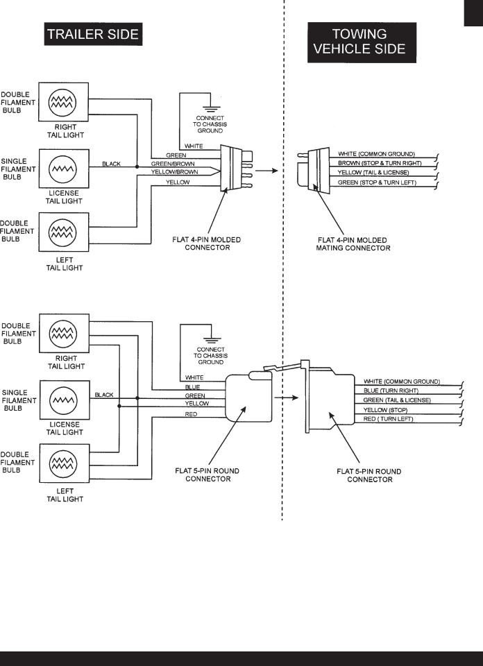
DCA-25SSIU —TRAILER-WIRING DIAGRAM
NOTE:
LIGHTS ARE ORIENTED FROM THE DRIVER’S SEAT
PAGE 16 — DCA-25SSIU — PARTS AND OPERATION MANUAL(STD) — REV. #7 (04/18//12)
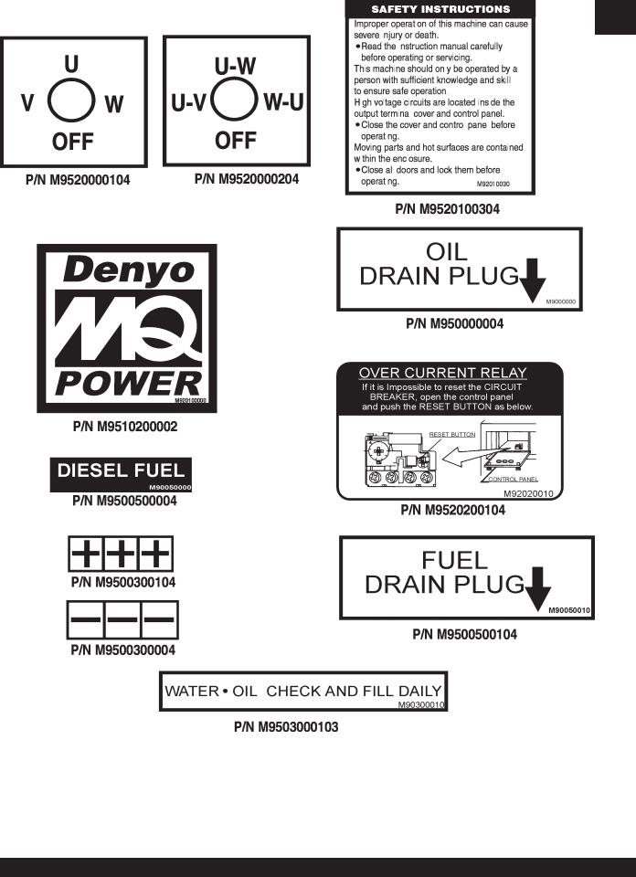
DCA-25SSIU — GENERATOR DECALS
The DCA-25SSIU generator is equipped with a number of safety decals. These decals are provided for operator safety and maintenance information. The illustration below and on the preceding pages show the decals as they appear on the machine. Should any of these decals become unreadable, replacements can be obtained from your dealer.
PAGE 17 — DCA-25SSIU — PARTS AND OPERATION MANUAL (STD) — REV. #7 (04/18/12)

DCA-25SSIU — GENERATOR DECALS
PAGE 18 — DCA-25SSIU — PARTS AND OPERATION MANUAL(STD) — REV. #7 (04/18//12)

|
|
DCA-25SSIU — SPECIFICATIONS |
|||
|
|
|
|
|
|
|
|
|
|
|
|
|
|
Table 5. Specifications |
|
||
|
|
|
|
|
|
|
|
Generator Specifications |
|
||
|
|
|
|
|
|
|
Model |
DCA-25SSIU |
|
||
|
|
|
|
|
|
|
Type |
Revolving field, self ventilated, open protected type synchronous |
|
||
|
|
|
|
|
|
|
Armature Connection |
Star with Neutral |
|
Zig Zag |
|
|
|
|
|
|
|
|
Phase |
3 |
|
Single |
|
|
|
|
|
|
|
|
Standby Output |
26.5 KVA (21.2 KW) |
|
15.3KW |
|
|
|
|
|
|
|
|
Prime Output |
25 KVA (20 KW) |
|
14.4KW |
|
|
|
|
|
|
|
|
Voltage |
240V or 480V |
|
240/120V |
|
|
|
|
|
|
|
|
Frequency |
|
|
60 Hz |
|
|
|
|
|
|
|
|
Speed |
|
1800 rpm |
|
|
|
|
|
|
|
|
|
Power Factor |
0.8 |
|
1 |
|
|
|
|
|
|
|
|
Aux. AC Power |
Single Phase, 60 Hz |
|
||
|
|
|
|
|
|
|
Voltage |
|
|
120 V |
|
|
|
|
|
|
|
|
Output |
4.8 KW (2.4 KW x 2) |
|
||
|
|
|
|
|
|
|
|
Engine Specifications |
|
||
|
|
|
|
|
|
|
Model |
Isuzu QD-6(C240) |
|
||
|
|
|
|
|
|
|
Type |
4 Cycle, water-cooled, swirl combustion chamber |
|
||
|
|
|
|
|
|
|
No. of Cylinders |
|
4 cylinders |
|
|
|
|
|
|
|
|
|
Bore x Stroke |
3.38 in. x 4 in. (86 mm x 102 mm) |
|
||
|
|
|
|
|
|
|
Rated Output |
30.6HP/1800 rpm |
|
||
|
|
|
|
|
|
|
Displacement |
144 cu. in. (2369cc) |
|
||
|
|
|
|
|
|
|
Starting |
|
Electric |
|
|
|
|
|
|
|
|
|
Coolant Capacity |
2.9 gal. (11 liters) |
|
||
|
|
|
|
|
|
|
Lube Oil Capacity |
1.45 gal. (5.5 liters) |
|
||
|
|
|
|
|
|
|
Fuel Consumption |
1.65 gal. (6.3L)/hr at full load |
|
1.3 gal. (5.0L)/hr at 3/4 load |
|
|
|
|
|
|
|
|
0.9 gal. (3.4L)/hr at 1/2 load |
|
0.6 gal. (2.3L)/hr at 1/4 load |
|
|
|
|
|
|
||
|
|
|
|
|
|
|
Battery |
|
12V70AH |
|
|
|
|
|
|
|
|
|
Fuel |
#2 Diesel Fuel |
|
||
|
|
|
|
|
|
PAGE 19 — DCA-25SSIU — PARTS AND OPERATION MANUAL (STD) — REV. #7 (04/18/12)

DCA-25SSIU — GENERAL INFORMATION
DCA-25SSIU FAMILIARIZATION
Generator
The MQ Power Model DCA-25SSIU is a 20 kW generator that is designed as a high quality portable (requires a trailer for transport) power source for telecom sites, lighting facilities, power tools, submersible pumps and other industrial and construction machinery.
Engine Operating Panel
The “Engine Operating Panel” is provided with the following:
Tachometer
WaterTemperature Gauge
Oil Pressure Gauge
Charging Ammeter Gauge
Fuel level gauge
Engine Throttle Lever
Pre-Heat Light
Alarm Lights
Panel Light
Panel Light Switch
Starter Switch
Generator Control Panel
The “Generator Control Panel” is provided with the following:
Output Voltage Adjustment Knob
Frequency Meter (Hz)
AC Ammeter (Amps)
AC Voltmeter (Volts)
Ammeter Change-Over Switch
Voltmeter Change-Over Switch
Main Circuit Breaker 60 amps
Over-Current Relay
Output Terminal Panel
The “Output Terminal Panel” is provided with the following:
Three 120V output receptacles, 50 amp
Two 120V output receptacles, 20 amp
3 Circuit Breakers 240V @65 amps
2 GFCI Circuit Breakers 120V@ 20amps
Open Delta Excitation System
The DCA-25SSIU generator is equipped with the state of the art "Open-Delta" excitation system. The open delta system consist of an electrically independent winding wound among stationary windings of the AC output section.
There are four leads: A, B, C and D. During light loads, the power to the AutomaticVoltage Regulator (AVR) is supplied from the leads parallel connections of B&C. When loads increase, the AVR switches and accepts power from leads
A&D. The output of leads A&D increase proportionally with load. This of adding the voltages to each phase provides better voltage response during heavy loads.
The connections of the AVR to the AC output windings are for sensing only. No power is required from these windings.
The open-delta design provides virtually unlimited excitation current, offering maximum motor starting capabilities. The excitation does not have a "fixed ceiling" and responds according the demands of the required load.
Engine
The DCA-25SSIU is powered by a 4 cycle, water cooled, turbocharged Isuzu QD60(C640) diesel engine.This engine is designed to meet every performance requirement for the generator. Reference Table 5, page 19 for engine specifications.
In keeping with MQ Power’s policy of constantly improving its products, the specifications quoted herein are subject to change without prior notice.
The basic controls and indicators for the DCA-25SSIU generator are addressed on the following pages.
Mechanical Governor System
The mechanical governor system control the RPM of the engine. When the engine demands increase or decrease, the mechanical governor system regulates the frequency to ±5%. The electronic governor option limits frequency fluctuation to ±0.25%.
PAGE 20 — DCA-25SSIU — PARTS AND OPERATION MANUAL(STD) — REV. #7 (04/18//12)
DCA-25SSIU — MAJOR COMPONENTS
Figure 4. Major Components
PAGE 21 — DCA-25SSIU — PARTS AND OPERATION MANUAL (STD) — REV. #7 (04/18/12)
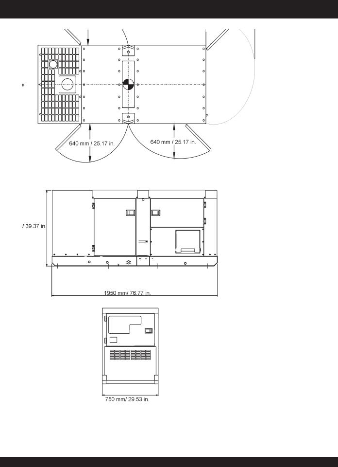
DCA-25SSIU — DIMENSIONS (TOP, SIDE AND FRONT)
Figure 5. Dimensions
PAGE 22 — DCA-25SSIU — PARTS AND OPERATION MANUAL(STD) — REV. #7 (04/18//12)

NOTE PAGE
PAGE 23 — DCA-25SSIU — PARTS AND OPERATION MANUAL (STD) — REV. #7 (04/18/12)
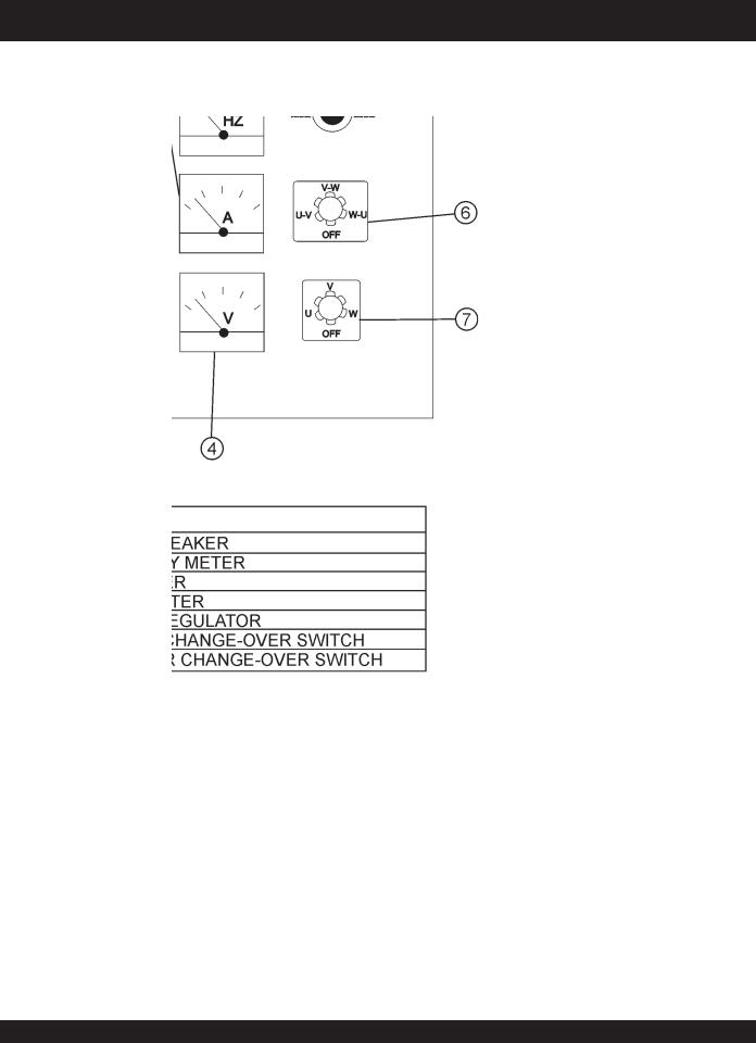
DCA-25SSIU — CONTROL PANEL
Figure 6. Control Panel
PAGE 24 — DCA-25SSIU — PARTS AND OPERATION MANUAL(STD) — REV. #7 (04/18//12)

DCA-25SSIU — CONTROL PANEL
The definitions below describe the controls and functions of the DCA-25SSIU " Control Panel " (Figure 6).
1.Main Circuit Breaker – This three-pole, 60 Amp main breaker is provided to protect the UNV voltage output terminals from overload.
2.Frequency Meter – Indicates the output frequency in hertz (Hz). Normally 63 Hz ±0.5 Hz .
3.AC Ammeter – Indicates the amount of current the load is drawing from the generator.
4.AC Voltmeter – Indicates the output voltage present at the UVW or output terminals.
5.Voltage Regulator Control – Allows manual adjustment of the generator’s output voltage.
6.Ammeter Change-Over Switch – This switch allows the AC ammeter to indicate the current flowing to the load connected to any phase of the output terminals, or to be switched off.
7.Voltmeter Change-Over Switch – This switch allows the AC voltmeter to indicate phase to phase voltage between any two phases of the output terminals or to be switched off.
PAGE 25 — DCA-25SSIU — PARTS AND OPERATION MANUAL (STD) — REV. #7 (04/18/12)
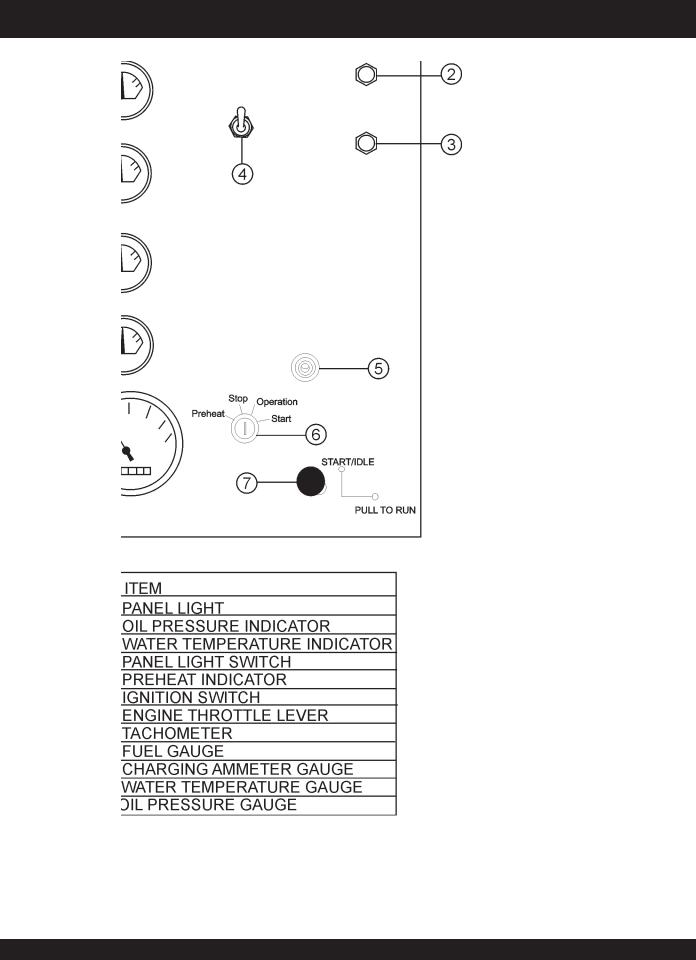
DCA-25SSIU — ENGINE OPERATING PANEL
Figure 7. Engine Operating Panel
PAGE 26 — DCA-25SSIU — PARTS AND OPERATION MANUAL(STD) — REV. #7 (04/18//12)

DCA-25SSIU — ENGINE OPERATING PANEL
The definitions below describe the controls and functions of the DCA-25SSIU " Engine Operating Panel " (Figure 7).
1.Panel light - Normally used in dark places or at night.
When activated, panel will luminate. When the generator is not in use, turn the panel light switch to the ‘OFF’ position.
2.Oil Pressure Lamp - This light will luminate if the oil pressure exceeds 15 psi and will shut off the engine.
3.Water Temperature Lamp - This light will luminate if the water temperature exceeds 215oF and will shut off the engine.
4.Panel light switch- When activated, will turn on control panel light.
5.Pre-Heat Indicator - This light will luminate once the engine is warmed to an operating temperature.
6.Ignition Switch - This switch is used with a key to start, preheat, and stop the engine..
7.Engine Throttle Lever - To change the speed of the engine from idle to high, pull and turn the handle.
8.Tachometer – Indicates engine speed in RPM’s for 60
Hz operation. This meter should indicate 1800 RPM’s when the rated load is applied. In addition a built in hour meter will record the number of operational hours that the generator has been in use.
9.Fuel Gauge - Indicates amount of diesel fuel available
10.Charging Ammeter Gauge – Indicates the current being supplied by the engine’s alternator which provides current for generator’s control circuits and battery charging system.
11.WaterTemperature Gauge – During normal operation this gauge be should read between 165o to 203oF.
12.Oil Pressure Gauge – Normal operation should be about 42~71 psi. When starting the generator the oil pressure may read a bit higher, but after the engine warms up the oil pressure should return to normal.
PAGE 27 — DCA-25SSIU — PARTS AND OPERATION MANUAL (STD) — REV. #7 (04/18/12)

DCA-25SSIU — OUTPUTTERMINAL PANEL
Output Terminal Panel
The output control panel is located on the rear (control panel) end of the generator. The UVW lugs are protected by a face plate cover that can be secured in the close position by a pad lock.
120Volt Receptacle
One GFCI Duplex NEMA 5-20R (120V, 20 Amp) receptacle is located on the output terminal. This receptacle can be used anytime the generator is in operation. The receptacle is controlled by the circuit breaker located on the control panel.
The reset button will reset the receptacle after being tripped. Pressing the "Test Button" (See Figure 8) in the center of this receptacle will check the GFCI function. The receptacle should be tested at least once a month.
Connecting Load
Loads can be connected to the generator by the UVW Lugs or the duplex receptacle. (See Figure 9). Make sure to read the operation manual before attempting to connect a load to the generator.
Figure 9. Connecting Loads
CircuitBreakers
To protect the generator from an overload, a 3-pole, 60 amp, main circuit breaker is provided to protect the UVWO output terminals from overload. In addition two single-pole, 20 amp
GFCI circuit breakers are provided to protect the GFCI receptacles from overload. Three 50 amp circuit breakers have also been provided to protect the load side of the generator from overload. Make sure to switch ALL circuit breakers to the "OFF" position prior to starting the engine.
Figure 8. GFCI Test Button |
Maximum Output |
|
The entire load connected to the UVW l ugs and all four slots in |
|
the duplex receptacle must not exceed 22 kW in standby or 20 |
|
kW in prime output. |
|
120V Receptacles - These receptacles can be used |
|
anytime the generator is in operation. They are controlled |
|
by the circuit breakers above them. |
|
Twist Lock Dual Voltage Receptacles - To use these |
|
receptacles, place the voltage selector switch in the single |
|
phase 240/120 voltage position and adjust the output |
|
voltage to 240 volts with the voltage regulator on the |
|
control panel (see Figure 6, page 24). Place the voltmeter |
|
change-over switch to the U-W position and the ammeter |
|
change-over switch to the U or W to read the output. |
PAGE 28 — DCA-25SSIU — PARTS AND OPERATION MANUAL(STD) — REV. #7 (04/18//12)
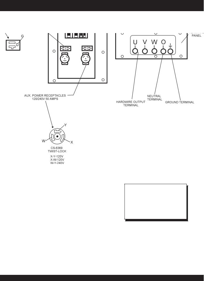
DCA-25SSIU — OUTPUTTERMINAL PANEL
NOTE
Legs “O” and Ground are considered Bonded Grounds.
Figure 10. Output Terminal Description
PAGE 29 — DCA-25SSIU — PARTS AND OPERATION MANUAL (STD) — REV. #7 (04/18/12)
DCA-25SSIU — OUTPUT AMPERAGE SETUP
Output Terminal Panel Available Voltages
A wide range of voltages are available to supply load to many different applications. Voltages may be selected by using the voltage selector switch and depending how you hookup your hard wire connection to the generator. To obtain voltages listed, fine adjustment with the voltage regulator on the control panel is necessary. See the table below (Table 6) for a list of available voltages the generator is able to supply.
Over Current Relay
An over current relay is connected to the circuit breaker. During an over current situation, both the circuit breaker and the over current relay may trip. If the circuit breaker can not be reset, the reset button on the over current relay must be pressed. The over current relay is located inside the control box.
Table 6. Voltage Available
3 Phase |
208 VOLT |
220 VOLT |
240 VOLT |
416 VOLT |
440 VOLT |
480 VOLT |
|
(Switchable) |
|||||||
|
|
|
|
|
|
||
|
|
|
|
|
|
|
|
Single Phase |
120 VOLT |
127 VOLT |
139 VOLT |
240 VOLT |
254 VOLT |
277 VOLT |
|
(Switchable) |
|||||||
|
|
|
|
|
|
||
|
|
|
|
|
|
|
CAUTION :
NEVER switch the voltage selector switch position while the engine is engaged.
Voltage Selector Switch Locking Button
The voltage selector switch has a locking button to protect the generator and generator load from being switched while the engine is running. To lock the voltage selector switch, press in the red button located on the lower part of the voltage selector switch, and use a pad lock to hold it into this position.
Maximum Amps
The following table show the maximum amps the entire generator can provide. Do not exceed the maximum amps listed. (See Table 7)
Table 7. Maximum Amps
Rated Voltage Maximum Amps
Single Phase
55.5 amps (4 wire)
120 Volt
Single Phase
27.8 amps (4 wire)
240 Volt
Three Phase
60 amps
240 Volt
Three Phase
30 amps
480 Volt
PAGE 30 — DCA-25SSIU — PARTS AND OPERATION MANUAL(STD) — REV. #7 (04/18//12)
 Loading...