


GTO 14001
1 CHANNEL POWER AMPLIFIER
SERVICE MANUAL
JBL Consumer Products |
|
250 Crossways Park Dr. |
|
Woodbury, New York 11797 |
Rev0 3/2008 |
Released 2008
Discontinued XXXX

GTO14001
- CONTENTS -
SPECIFICATIONS ………………………………………..1
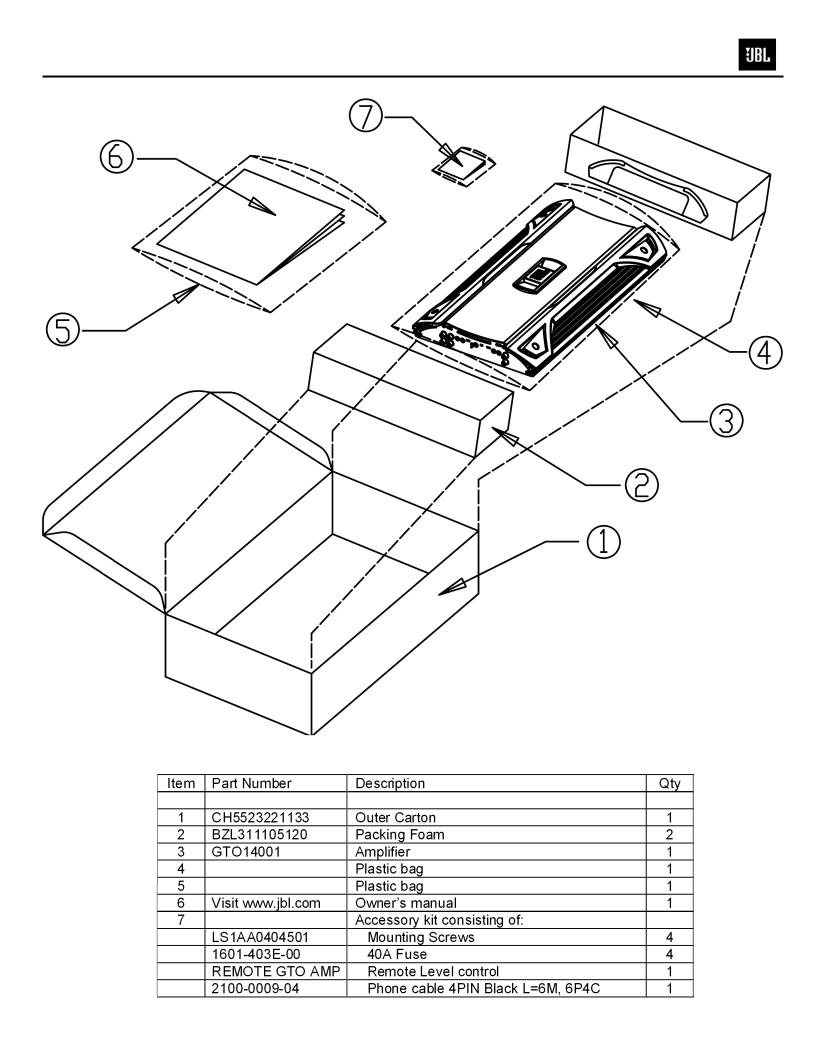
PACKING……………………………………………..…....2
CONTROL/INSTALLATION DRAWINGS………………3
CONTROL/INSTALLATION INSTRUCTIONS………....4
BASIC TROUBLESHOOTING……………………………5
EXPLODED VIEW/PARTS LIST…….….….…………....6
AMPLIFIER BLOCK DIAGRAM…………………….……7
ELECTRICAL PARTS LIST ..……….……….…….…….8
P.C.B. DRAWINGS….………………………..…….……13
IC/TRANSISTOR PINOUTS..………………..….….…..20
SCHEMATICS……………..……………….………..…...21
GTO 14001 Specifications
Output Power: |
1200W RMS x 1 channels @ 4 ohms; ≤1% THD + N |
(14.4V supply) |
1500W RMS x 1 channels @ 2 ohms; ≤1% THD + N |
Signal-to-noise ratio: |
77dBA (reference 1W into 4 ohms) |
|
108dBA (reference rated power into 4 ohms) |
Dynamic power: |
1800W @ 2 ohms |
Frequency response: |
20Hz – 300Hz (–3dB) |
THD+N 1KHz LPF=22KHz |
≤0.05% (rated power @ 4 ohms) |
Input Impedance |
>20K ohms |
Maximum input signal: |
6.0V |
Maximum sensitivity: |
100mV |
Bass Boost @ 20-100Hz |
0-12dB (±2dB) |
DC Offset |
<30mV |
Output regulation: |
.03dB @ 4 ohms |
Idle Current @ 2 ohms |
1.8A |
Max Current Draw |
140A @ 2 ohms |
Remote Operating Voltages |
ON 5V OFF 3.5V |
Turn-on delay time |
2-3 sec |
Circuit Protection |
Temperature (80±5C), Short circuit |
Operating voltage range |
(8-16V) |
Dimensions: |
18 9/16 x 10 3/8 x 2 1/8” (470 x 263 x 53mm) |
Fuses: |
(4) x 40A |
JBL continually strives to update and improve existing products, as well as create new ones. The specifications and details in this and related JBL publications are therefore subject to change without notice.
1
GTO14001
2
GTO14001
4x |
2x |
1x |
|
|
1x |
|
4x |
1x |
10-3/8" 263mm
|
|
|
|
|
|
|
|
|
|
|
|
|
|
|
|
|
|
|
|
|
|
|
|
|
|
|
|
|
|
|
|
0 |
1 |
2 |
|
18-9/16" |
|
|
|
|
|
|
|||||
|
|
|
|
|
|
|
|
|
|
||||||
|
|
|
|
|
|
|
|
|
470mm |
||||||
2-1/8" 


 53mm
53mm 


 D
D 


 3 4 9 A 8


|
5 6 |
7 |
|
|
A B |
B |
|
C |
A |
B C |
D |
|
|
A |
1"
25mm
1-5/8"
40mm
8
3
GTO14001
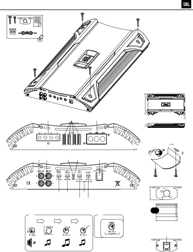
GTO14001 CAR AUDIO SUBWOOFER AMPLIFIER
Installation Warnings and Tips
•Disconnect the negative (–) lead from your vehicle’s battery.
•At the installation sites, locate and make a note of all fuel lines, hydraulic brake lines, vacuum lines and electrical wiring. Use extreme caution when cutting or drilling in and around these areas.
•Choose a safe mounting location away from moisture.
•Make sure there is sufficient air circulation at the mounting location for the amplifier to cool itself.
•Mount the amplifier, using the supplied hardware.
Specifications
•1200W RMS x 1 channel @ 4 ohms and ≤1% THD + N*
•1500W RMS x 1 channel @ 2 ohms and ≤1% THD + N*
•THD + N: 0.05% (rated power @ 4 ohms)
•Signal-to-noise ratio: 77dBA (reference 1W into 4 ohms)*
•Signal-to-noise ratio: 108dBA (reference rated power into 4 ohms)
•Frequency response: 20Hz – 330Hz (–3dB)
•Max power: 1500 watts
* CEA-2006A-compliant
0 Speaker Output Connectors
•Connect the speakers to these terminals, observing proper polarity. Either + or – terminal may be used. Minimum total impedance is 2 ohms.
1 Fuses
•Replace only with the same type and rating.
2 Power Input Connectors
•+12V: Connect to the positive terminal of the vehicle’s battery. 4 AWG wire is recommended. Install an appropriate fuse holder and fuse (160A minimum) within 18 inches of the battery. Make sure the wire is not damaged or pinched during installation. Install protective grommets when routing wires through the firewall or other sheet metal.
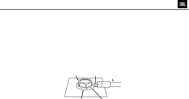
•GND: Connect to the vehicle’s chassis. Refer to the picture below.
Factory Bolt |
Ring Connector |
Gr
Note: Remove any paint S Washer below r r.
•REM: Connect to the “Remote Out” lead from the source unit or to a source of switched 12V+ (ACC).
3 Aux Output Connectors (RCA)
•Nonfiltered pass-through output. Connect to the input of an additional amplifier.
4 Input Connectors (RCA)
•Connect to the RCA outputs from the source unit or signal processor.
5 Input-Level Control
•Used to match the input level of the amplifier to the output level of the source unit.
•See Bfor the adjustment procedure.
6 Low-Pass Filter Frequency Control
•12dB/octave low-pass filter, variable from 32Hz to 320Hz.
•See Cfor the adjustment procedure.
7DBO (Dynamic Bass Optimization) Variable
Subsonic High-Pass Filter With Variable Boost (Q)
•For woofers in tuned (vented) enclosures, set the Frequency control to a value 10Hz below the enclosure’s resonance (tuned) frequency.
•For woofers in sealed boxes, set the control to any value you prefer, between 30Hz and 50Hz.
•Set the Boost control according to your preference, being careful not to apply enough boost to damage your woofer(s).
ADBO High-Pass Filter Frequency control, variable between 10Hz and 100Hz. See above for appropriate settings.
BDBO Boost control provides up to 12dB of boost, slightly above the highpass filter’s frequency. See above for appropriate settings.
8Remote Level Control (RLC) Connector
•Connect the Remote Level Control (RLC) here, using the supplied RJ-11 cable.
9Power On LED
•Illuminated when the amplifier is on.
AProtect LED
•Illuminated under any of the following fault conditions: battery over/under voltage, short circuit in speaker wires, amplifier is too hot, amplifier’s output circuit has failed (DC voltage is present in the amplifier’s output).
BSetting Input Level
ATurn Input Level control counterclockwise to 6V (minimim).
BWith a dynamic music track playing, turn the head unit’s volume control to the 3/4 position.
CTurn Input Level control clockwise until the bass output is proportionate to the output of the high-frequency speakers, according to your preference.
DInput level is now adjusted correctly.
CSetting the Crossover
ACrossover setting for subwoofers.
Note: Acceptable frequency ranges are indicated in gray.
DRemote Level Control
The Remote Level Control, if installed, will allow you to adjust the level of bass while seated in the listening position.
4

GTO14001
Amplifier Troubleshooting Guide
1.Status LED on Amplifier not Lit - Head Unit (Source) Turned ON Verify:
A.Remote turn-on wire from source to amplifier has proper voltage
B.Power (B+) connections at amplifier, terminal blocks, and battery are secure
C.Ground (GND) connections at amplifier and vehicle chassis are secure
D.Battery B+ fuse (if used) is OK
E.Amplifier fuse is OK
F.B+ at battery and B+ at amplifier has proper voltage
2.Status LED’s Lit, No Output from Speakers in Normal Operating Condition
Verify:
A.RCA cables from amplifier to source are securely connected
B.Volume adjustment on amplifier is correctly adjusted
C.Source is ON and playing
3.Engine Noise From Speaker(s)
Turn source OFF, Disconnect RCA cables at amplifier. If noise stops, check equipment & cables leading to amplifier.
Verify:
A.RCA cables are of good quality with no breakage to internal shields
B.RCA cables from source to amplifier are not run alongside any power cables
4.Amplifier Output Distorted Music
Verify:
A.Source output music to amplifier is not distorted
B.Source output sensitivity is correctly adjusted
5.Amplifier Shuts Down, Green LED’s are Lit - Amplifier is in Thermal Protection Mode Verify:
A.Amplifier is mounted with adequate air circulation around heatsinks or vents
B.Amplifier is not mounted under carpet or sealed enclosure
C.Speakers meet correct impedance for application (mono or stereo hookup)
6.Amplifier Does Not Turn ON, and Red LED is Lit Amplifier (and not Connected to a Shorted Speaker) Verify:
A.Speaker crossover (if used) is not defective
5

GTO14001
Trans. Clamp |
Trans. Clamp |
Trans. Clamp |
RCA CAP (Red) |
RCA CAP (Wht) |
Front Plate |
Standoff |
6
GTO14001 |
|
|
|
|
|
|
|
|
|
BALANCED |
|
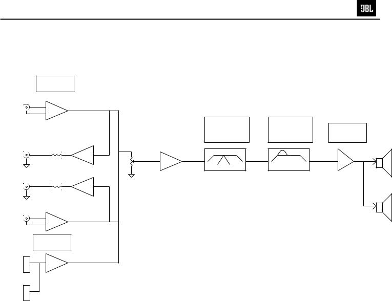
Block Diagram |
GTO14001 |
|
|
|
|||
INPUT UNIT |
|
|
|
|
|||||
|
UnRegistered |
|
|
||||||
INPUT L |
|
|
|
|
|||||
|
|
|
|
|
|
|
|
|
|
1 |
OP |
|
|
|
|
|
|
|
|
2 |
|
|
|
|
|
|
|
|
|
|
|
|
LP FREQ |
BASSBOOST |
|
||||
|
|
|
VARIABLE |
VARIABLE |
MAIN AMP |
||||
|
|
|
32Hz-320Hz/12dB |
0dB-12dB/50Hz |
|||||
|
|
|
2 ohm/4 ohm |
||||||
OUTPUT L |
|
|
GAIN CONTROL |
|
|
|
|
|
|
|
|
|
|
|
|
|
|
||
|
OP |
|
|
|
|
|
|
|
|
|
|
32 |
80 |
320Hz |
32 |
50 |
320Hz |
|
|
|
|
|
OP |
|
|
|
|
|
AMP |
OUTPUT R |
|
OP |
|
|
|
|
|
|
SPEAKER |
|
|
|
|
|
|
|
|
||
INPUT R |
|
|
|
|
|
|
|
|
|
1 |
OP |
|
|
|
|
|
|
|
|
2 |
|
|
|
|
|
|
|
2 ohm/4 ohm |
|
|
|
|
|
|
|
|
|
|
|
BALANCED |
|
|
|
|
|
|
|
|
|
INPUT UNIT |
|
|
|
|
|
|
|
|
|
|
OP |
|
|
|
|
|
|
|
|
IMS INPUT |
|
|
|
|
|
|
|
|
|
|
|
|
7 |
|
|
|
|
|
|
 Loading...