


JP340
Ge JP340, JP938, JP968, JP960, JP930 User Manual
...
C
GE Consumer Home Services Training
TECHNICAL SERVICE GUIDE
Electronic Touch Control
&
Electric Manual Control
Cooktops
MODEL SERIES:
Electronic: JP938
JP968
Electric: JP340
JP350
JP930
JP960
PUB # 31-9070 01/01

!
IMPORTANT SAFETY NOTICE
The information in this service guide is intended for use by
individuals possessing adequate backgrounds of electrical,
electronic, and mechanical experience. Any attempt to repair a
major appliance may result in personal injury and property
damage. The manufacturer or seller cannot be responsible for the
interpretation of this information, nor can it assume any liability in
connection with its use.
WARNING
To avoid personal injury , disconnect power before servicing this
product. If electrical power is required for diagnosis or test
purposes, disconnect the power immediately after performing the
necessary checks.
RECONNECT ALL GROUNDING DEVICES
If grounding wires, screws, straps, clips, nuts, or washers used
to complete a path to ground are removed for service, they must
be returned to their original position and properly fastened.
GE Consumer Home Services Training
Technical Service Guide
Copyright © 2000
All rights reserved. This service guide may not be reproduced in whole or in part
in any form without written permission from the General Electric Company.

Table of Contents
Table of Contents
Introduction . . . . . . . . . . . . . . . . . . . . . . . . . . . . . . . . . . . . . . . . . . . . . . . . . . . . . 2
Installation . . . . . . . . . . . . . . . . . . . . . . . . . . . . . . . . . . . . . . . . . . . . . . . . . . . . . . 3
Specifications and Nomenclature5 . . . . . . . . . . . . . . . . . . . . . . . . . . . . . . . . . . 5
Warranty Information. . . . . . . . . . . . . . . . . . . . . . . . . . . . . . . . . . . . . . . . . . . . . . 6
Cooktop Features and Controls . . . . . . . . . . . . . . . . . . . . . . . . . . . . . . . . . . . . 7
Diagnostics . . . . . . . . . . . . . . . . . . . . . . . . . . . . . . . . . . . . . . . . . . . . . . . . . . . . 12
Mechanical Disassembly . . . . . . . . . . . . . . . . . . . . . . . . . . . . . . . . . . . . . . . . . 18
Component and Connector Locator Views . . . . . . . . . . . . . . . . . . . . . . . . . . 27
Schematics . . . . . . . . . . . . . . . . . . . . . . . . . . . . . . . . . . . . . . . . . . . . . . . . . . . . 30
Parts List . . . . . . . . . . . . . . . . . . . . . . . . . . . . . . . . . . . . . . . . . . . . . . . . . . . . . . 32
Quiz . . . . . . . . . . . . . . . . . . . . . . . . . . . . . . . . . . . . . . . . . . . . . . . . . . . . . . . . . . 36
[[Title]]
– 1 –
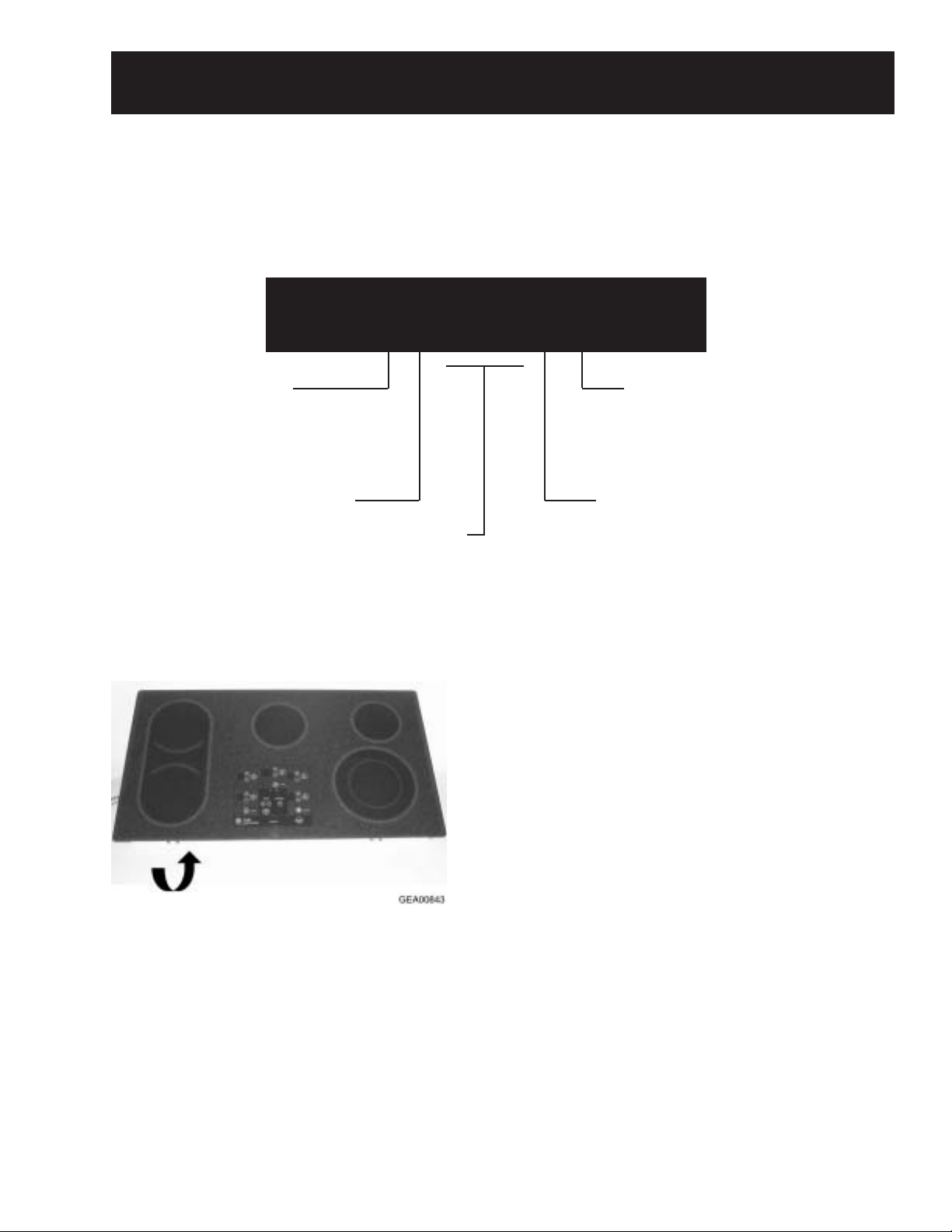
Introduction
The new electronic cooktops make an eloquent
statement of style, convenience, and kitchen
planning flexibility . The electronic touch controls
are simple to understand and easy to operate–just
read and touch.
These cooktops include many helpful features. The
pan detection feature automatically shuts the
heating element OFF after 60 seconds of removing
a metallic pan from the heater . The pan sizing
feature adjusts the heated portion of the dual
element to fit the size of a metallic pan. And the
new warming feature keeps sauces and gravies
warm–or can be used as a normal heating element.
The controls lockout feature protects against
power activation to a heating element during times
of unintended usage or when cleaning the cooktop.
And the convenient kitchen timer can be used with
or without operating the heating elements to
simplify any kitchen task that requires a countdown timer.
It’s easy to see how GE’s fresh ideas can make
anyone more creative in the kitchen!
The information on the following pages will help
you service these new electronic and electric
cooktops effectively and efficiently.
– 2 –
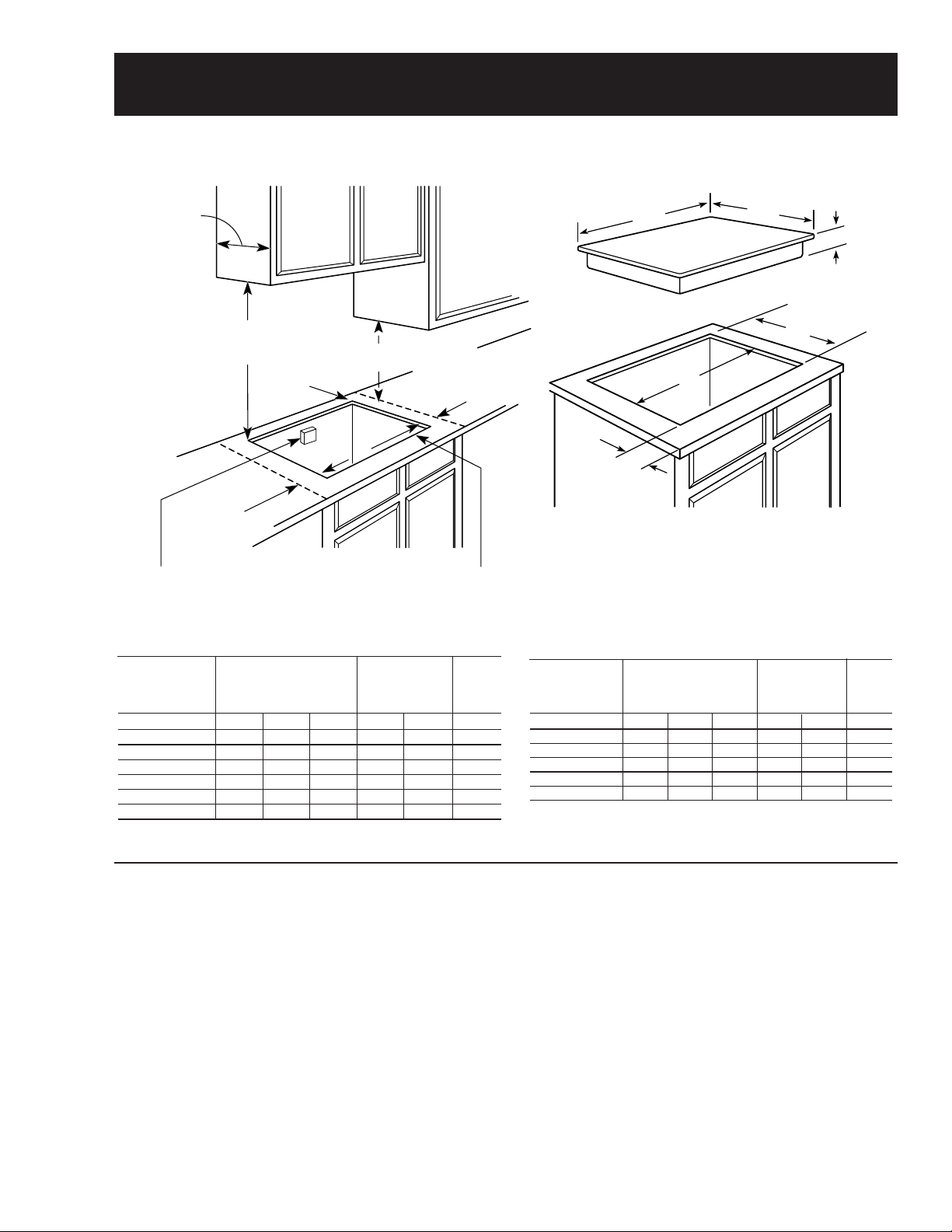
Installation
Electrical junction
box 16" MIN.
below countertop
30" MIN. to
unprotected
cabinet
Cut should not interfere
with cabinet structure
at front
1-3/4" MIN.
clearance to
side wall
from cut-out
1-1/2" MIN.
clearance to
side wall
from cut-out
18" MIN.
to cabinet
1-3/4" to
rear wall
13" MAX.
depth
A
Cooktop
G
E
F
W
D
Counter Installation Dimensions (in inches)
Required
Cooktop Dimensions (in inches)
GEA00791
Dimensions (in inches)
Overall
Model
JP968WC/CC/BC 36 20-3/8 3-1/4* 33-7/8 19-1/8 2-1/2
JP960TC/CC/BC 36 20-3/8 3-1/4* 33-7/8 19-1/8 2-1/2
JP938WC/CC/BC 29-3/4 20-7/8 3-1/4* 28-1/2 19-5/8 2-1/2
JP930TC/CC/BC 29-3/4 20-7/8 3-1/4* 28-1/2 19-5/8 2-1/2
JP350TC/WC/CC/BC
JP340WC/BC 29-3/4 20-7/8 3-1/4* 28-1/2 19-5/8 2-1/2
*Depth of unit at conduit connection location (rear) is 6-1/4" on models JP968/938
and 4-5/8" on models JP960/930/350/340.
WD A E FG
29-3/4 20-7/8 3-1/4* 28-1/2 19-5/8 2-1/2
36-in. and 30-in. Cooktops
Refer to installation instructions. Installation
requires an 18-in. minimum distance from
cooktop to adjacent overhead cabinets. Units are
furnished with a 48-in. flexible armored cable.
Cooktop installation requires a 5-in. free area
between the bottom of the cooktop and any
combustible material, such as shelving. This 5-in.
area is not required when installing a wall oven
underneath the cooktop.
The 36-in. cooktops are approved for use over
GE 30-in. single wall ovens only. The 30-in.
Stainless Steel Cooktop Dimensions (in inches)
To Edge
of Front
Cutout (Min.)
Counter
Model
JP968SC 36-1/8 21 3-1/4* 33-7/8 19-1/8 2-1/2
JP960SC 36-1/8 21 3-1/4* 33-7/8 19-1/8 2-1/2
JP938SC 29-7/8 21-1/2 3-1/4* 28-1/2 19-5/8 2-1/2
GEA00792
JP930SC 29-7/8 21-1/2 3-1/4* 28-1/2 19-5/8 2-1/2
JP350SC 29-7/8 21-1/2 3-1/4* 28-1/2 19-5/8 2-1/2
*Depth of unit at conduit connection location (rear) is 6-1/4" on models JP968/938
and 4-5/8" on models JP960/930/350.
cooktops are approved for use over select GE
27-in. and GE 30-in. single wall ovens.
Note: If installing with a GE Profile Performance™
or GE Profile™ Telescopic Downdraft System,
consult both cooktop and downdraft installation
instructions packed with the products before
installing. Cooktop electric supply may need to be
rerouted to install the downdraft ventilation.
Note: Consult the cabinet and countertop
manufacturer’s specs for flush-mount installation
prior to installing.
– 3 –
Overall
WD A E FG
Cutout (Min.)
To Edge
of Front
Counter
GEA00793
Grounding Specifications
Ground Path Resistance 0.10 ohms Max.
Insulation Resistance 250K ohms Min.
Power Supply Requirements
The cooktop must be connected to a supply
circuit of the proper voltage and frequency as
specified on the rating plate. The rating plate is
located on the side of the component box. Wire
size must conform to the National Electrical
Code or the prevailing local code.
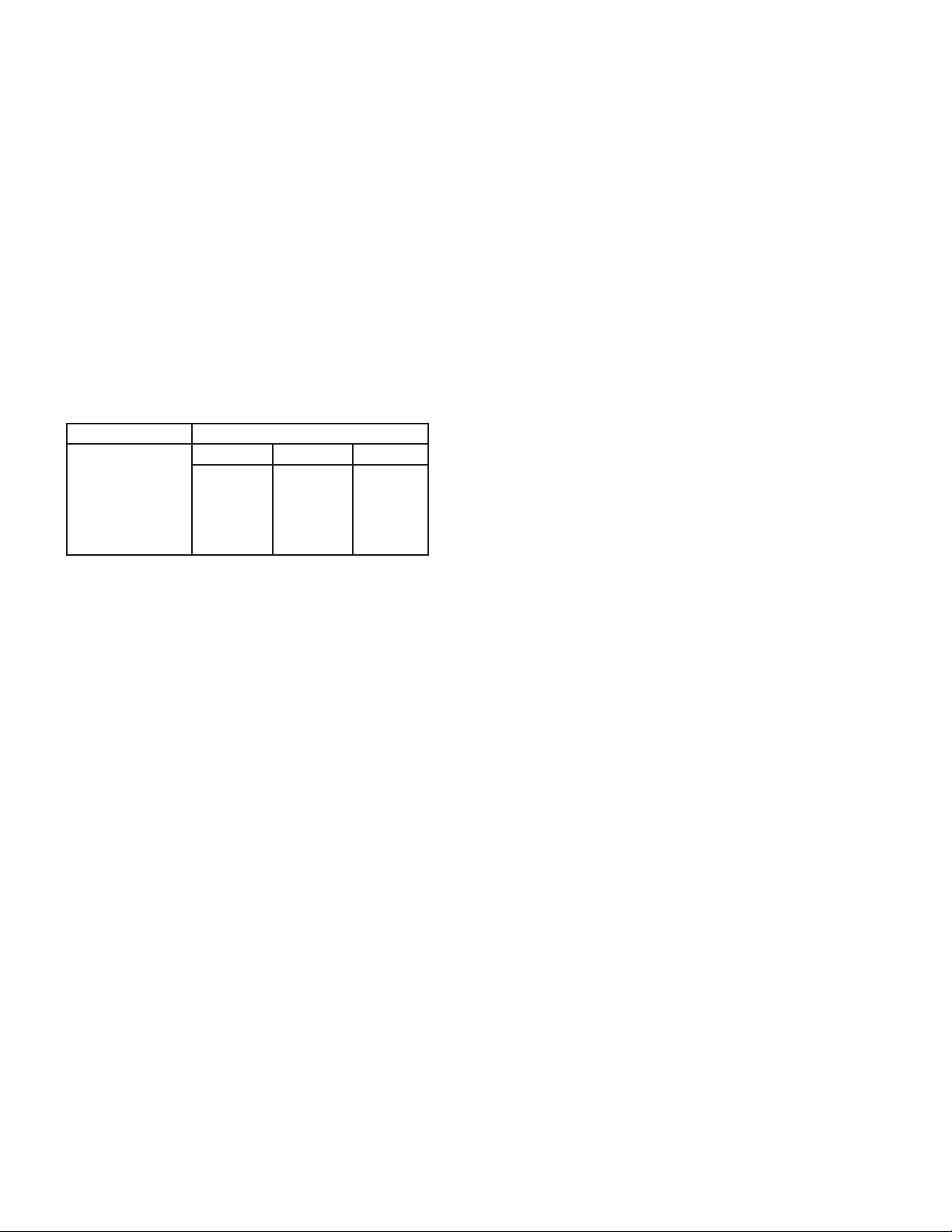
Overcurrent Protection for
Counter-Mounted Cooktops
for a counter-mounted cooktop and not more
than two wall-mounted ovens – all supplied from
a single branch circuit and located in the same
room – shall be computed by adding the nameplate ratings on the individual appliances and
treating this total as equivalent to one range.
Wiring
Built-in power leads are U.L. approved for connection to larger gauge household wiring. The
insulation of these leads is rated at temperatures
much higher than the temperature rating of household wiring. The current carrying capacity of a
conductor is governed by the temperature rating
of the insulation around the wire rather than the
wire gauge alone.
NEC RATING
20 Amp
30 Amp
35 Amp
40 Amp
50 Amp
MAXIMUM KILOWATT RATING
208V 236V 240V
4.2 4.7 4.8
6.2 7.1 7.2
7.3 8.3 8.4
8.3 9.4 9.6
10.4 12.0
11.8
GEA00794
The branch circuit load for one countermounted cooktop is the rating on the nameplate of the appliance. The branch circuit load
WARNING: Improper connection of aluminum
house wiring to these copper leads can result in a
serious problem. Use only connectors designed
for joining copper to aluminum and follow the
manufacturer’s recommended procedure closely.
– 4 –
Specifications and Nomenclature
For specifications table, refer to Cooktop Features and Controls, page 11.
Model Number
J P 9 6 8 B C
Product
J = GE Cooking Product
Configuration
P = Cooktop
Feature Pack
Designates features–the higher
the number, the more features.
The serial plate of your cooktop is located
on the bottom of the burner box. In addition
to the model and serial numbers, this plate
tells you the power ratings of the supply
circuit for the cooktop.
Grate Type
C = Continuous
Glass Color
B = Black glass
Serial Number
The first two numbers of the serial number
identify the month and year of manufacture.
Example: AZ123456S = January, 2000
A - JAN 2005 - H
D - FEB 2004 - G
F - MAR 2003 - F
G - APR 2002 - D
H - MAY 2001 - A
L - JUN 2000 - Z
M - JUL 1999 - V
R - AUG 1998 - T
S - SEP 1997 - S
T - OCT 1996 - R
V - NOV 1995 - M
Z - DEC 1994 - L
The letter designating the
year repeats every 12
years.
Example:
T - 1974
T - 1986
T - 1998
Note: The technical sheet is located under the
control panel.
– 5 –
Warranty Information
Sales slip or cancelled check is required as proof of original purchase date to obtain
service under warranty.
All warranty service is provided by our Factory Service Centers or an authorized Customer Care® technician.
For The Period Of:
One Year
From the date of the
original purchase
Five Years
From the date of the
original purchase
GE Will Replace:
Any part of the cooktop that fails due to a defect in materials or workman-
ship. During this full one-year warranty, GE will also provide, free of
charge, all labor and in-home service to replace the defective part.
Glass-Ceramic Cooktop, Ribbon Heating Elements and Rubber Seal, if
any of these parts should fail due to a defect in materials or workmanship.
During this limited additional four-year warranty, GE will replace the
defective part free of charge, you will be responsible for service trips and
labor charges.
What GE Will Not Cover:
• Service trips to your home to teach you
how to use the product.
• Improper installation.
• Failure of the product if it is abused, misused, or used for other than the intended
purpose or used commercially.
• Damage to the glass cooktop caused by
use of cleaners other than the recommended cleaning creams.
• Replacement of house fuses or resetting of
circuit breakers.
• Damage to the product caused by accident,
fire, floods, or acts of God.
• Incidental or consequential damage to
personal property caused by possible
defects with this applicance.
• Damage to the glass cooktop caused by
hardened spills of sugary materials or
melted plastic that are not cleaned according to the directions in the Owner’s Manual.
This warranty is extended to the original purchaser and any succeeding owner for products purchased
for home use within the USA. In Alaska, the warranty excludes the cost of shipping or service calls to
your home.
Some states do not allow the exclusion or limitation of incidental or consequential damages. This warranty gives you specific legal rights, and you may also have other rights which vary from state to state.
To know what your legal rights are, consult your local or state consumer affairs office or your state’s
Attorney General.
Warrantor: General Electric Company, Louisville, KY 40225
– 6 –
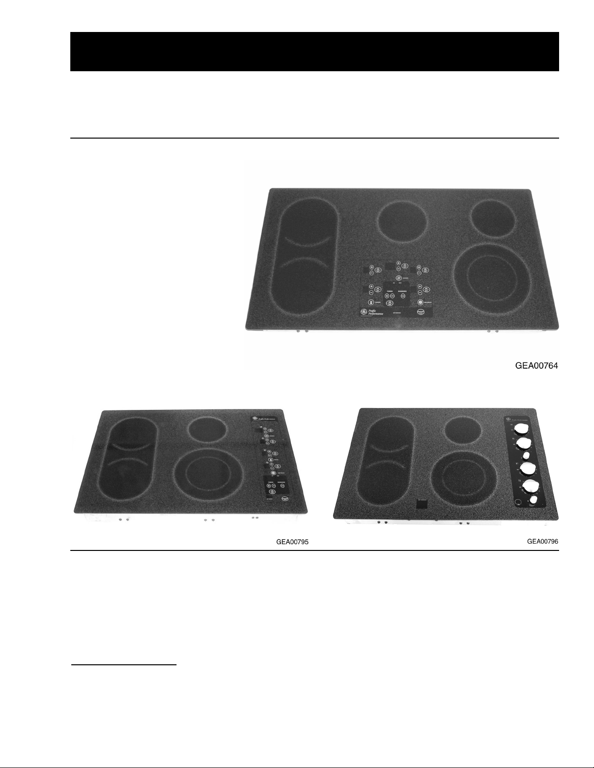
Cooktop Features and Controls
Throughout this manual, features and appearances may vary from the customer’s model.
The new Electronic Touch Control and Electric Manual Control Cooktops encompass over 20 models of
cooktops. They include 30-in., 4-burner and 36-in., 5-burner radiant glass cooktop configurations.
Feature Index
1. Frameless Glass Cooktop
2. Electronic Touch Controls*
3. Pan Detection*
4. Pan Sizing*
5. Control Lock-out*
6. Kitchen Timer*
7. Ribbon-T ype Heating Elements
8. 7-in. Heating/Warming Element*
*Some Models, JP938 & JP968
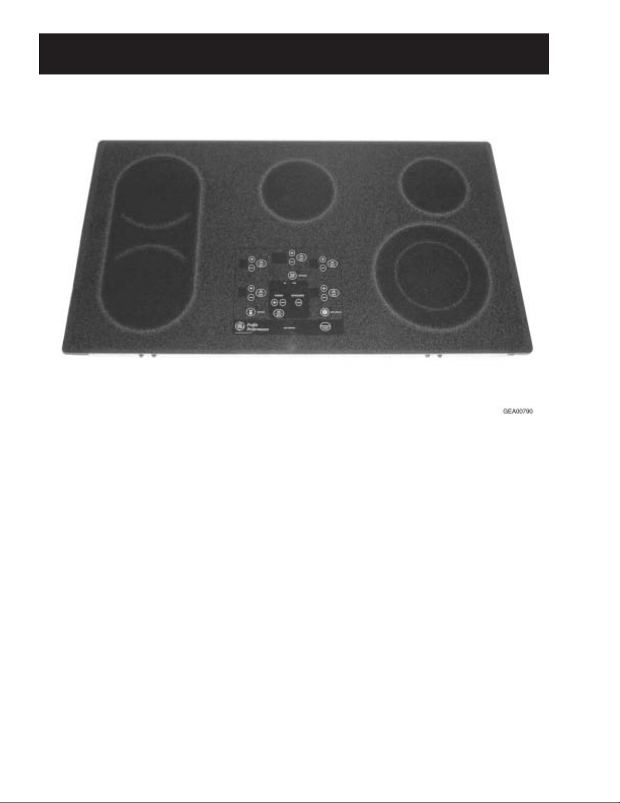
JP938 (30-in.) Electronic Cooktop
JP968 (36-in.) Electronic Cooktop
JP930 (30-in.) Electric Cooktop
Ceramic Glass Surface
These cooktops feature a ceramic glass cooking
surface over an electric radiant surface element.
The electronic models feature touch controls on
this glass surface that take the place of control
knobs.
Appearance Defects
Scratches, marks from cooking utensils, discoloration, stains, spots, etc. can be caused by food
soils, cookware, cleaning solutions, or water
marks.
Before replacing the cooktop, try using the
cooktop cleaning procedure outlined in the
Owner’s Manual, using the cleaning cream and
Scotch Brite® pad shipped with the product.
Note: When servicing the cooktop, care must be
taken not to scratch or damage the glass.
– 7 –
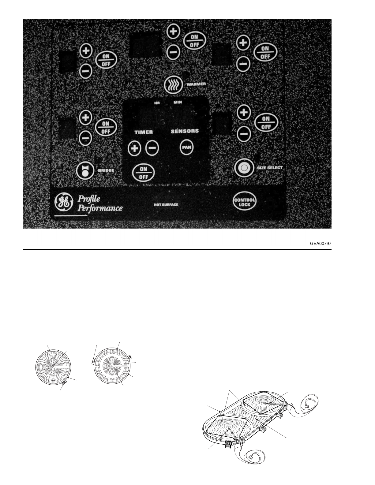
Heating Element Systems
Bridge Element
The Haliant Surface Element consists of a ribbontype resistance wire attached to the support insulation with molded ceramic fiber walls in a corrosionprotected metal dish.
These circular heating elements come in the three
sizes listed below.
Ceramic
Fiber
Molded
Wall
Hot
Light
9" Dual Unit 240 Volt 2500 Watts
9" Ribbon Heating
Element
4
4
Supporting
Insulation
Ceramic Fiber
Molded Wall
6" Ribbon Heating
Element
(6"-1000W., 9"-1500W)
GEA00798
Ribbon Heating
Element
7" 240 Volt-1500 Watts
Hot Light
6" 240 Volt-1200 Watts
Supporting
Insulation
– 8 –
The Bridge Element is made up of two 7-in.,
1800 watt elements plus an 800 watt element
between the two 7-in. elements. The elements
consist of a ribbon-type resistance wire attached
to support insulation with molded ceramic walls.
The digital control on the electronic models (or
the infinite heat switches on the electric models)
regulates the 7-in. units independently of each
other, or in combination when the bridge operating mode (or switch) is selected. The bridge and
the left front element are regulated by the same
controls.
7"-1800 Watt
Elements
Molded
Ceramic
Wall
RTD
RTD
800 Watt
Bridge
Element
GEA00902
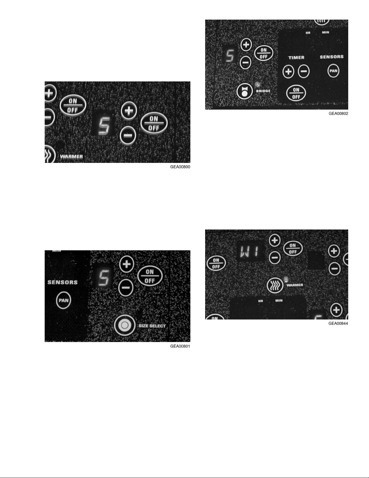
Electronic T ouch Controls (Some Models,
JP938 & JP968)
The touch controls provide precise control of the
surface elements. You can quickly switch from a
steady low heat to full power or any setting in
between.
To turn ON a standard surface element, touch the
ON/OFF pad, then touch the (+) or (-) pad. The
surface element will energize to power setting 5.
Use the (+) or (-) pads to choose the desired
setting: L (low), 1-9, or H (high). The control will
beep each time the pad is touched. To turn the
surface element OFF, touch the ON/OFF pad
again.
To turn ON the bridge element, set the left front
surface element to the desired setting. Touch the
BRIDGE pad. The bridge element will energize to
the same level as the left front surface element
...or, touch the ON/OFF pad for the left front
surface element, then touch the BRIDGE pad.
The left front and bridge elements will both
energize to power setting 5. Using the (+) or (-)
pads will control the setting for both elements. To
turn the bridge element OFF, touch the BRIDGE
pad again. Touching the ON/OFF pad will turn
OFF both the left front and the bridge elements.
To turn ON a 9-in. dual surface element, touch the
ON/OFF pad, then touch the (+) or (-) pad. The
small surface element will energize to power
setting 5. Touch the SIZE SELECT pad to energize
both large and small surface elements. Use the (+)
or (-) pads to choose the desired setting. To turn
the large surface element OFF, touch the SIZE
SELECT pad again. To turn both the large and
small surface elements OFF, touch the ON/OFF
pad.
– 9 –
To turn ON the warmer surface element, touch
the ON/OFF pad, then touch the WARMER pad.
If the surface element is already in use, touch the
WARMER pad. The surface element will energize
to the warmer power setting W1. Use the (+) or
(-) pads to choose the desired warmer setting:
W1, W2, or W3.
To turn OFF the warmer power setting, touch the
WARMER pad again. The surface element will
remain ON in power setting L (low). To turn OFF
the surface element, touch the ON/OFF pad
again.
Indicator Lights
Lights will come ON next to the bridge, warmer ,
dual unit, or control lockout pads when touched,
to indicate the surface element or feature is
energized. The light will go OFF when the surface element or feature is turned OFF.
HOT SURF ACE Indicator Lights
The HOT SURFACE indicator lights will glow
when any surface unit is turned ON and will
remain on until the surface has cooled to approximately 150°F.
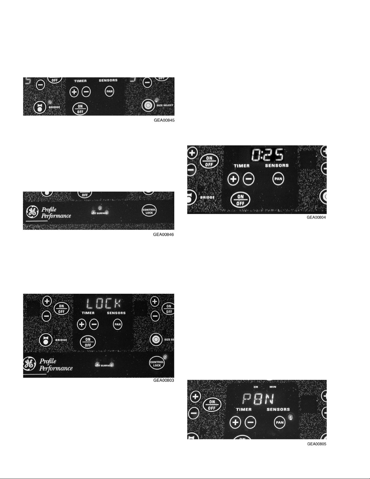
TROL LOCK pad again for 3 seconds. A
2-beep signal will sound and the light will go
out, indicating the cooktop is unlocked.
Locking the cooktop will prevent surface
elements from accidentally being energized by
children or pets. You may lock the cooktop
when not in use or before cleaning.
Kitchen Timer
Operate the timer using the pad below the timer
display . Touch the ON/OFF pad, then touch the
(+) or (-) pad to choose the desired time setting.
If the (+) or (-) pad is held for several seconds,
Controls Lockout
Note: For your convenience, the entire cooktop
can be locked at any time.
To lock the cooktop, touch and hold the CONTROL LOCK pad for 3 seconds. A 2-beep signal
will sound, the word LOCK will appear in the
timer display, and the CONTROL LOCK light will
turn ON indicating the cooktop is locked. If the
cooktop is locked while the surface elements or
timer are in use, they will automatically turn OFF.
the timer will increase or decrease at a faster
rate. After choosing your desired time, the timer
will automatically start to count down from the
hours/minutes you have selected. When the
timer reaches 1 minute, the control will beep
once and the timer will display the remaining
time in seconds until 00:00. The control will then
beep twice every 5 seconds until the timer is
turned OFF.
Pan Detection
Note: For this feature to function properly, the
metallic pan must be at least 4 in. in diameter
and centered on the surface element. This
feature will not work with glass cookware and
must be turned OFF when glass cookware is
used.
To unlock the cooktop, touch and hold the CON-
The pan detection feature works in the following
– 10 –
 Loading...