


19XRV with PIC III Controls Rockwell PowerFlex 755 VFD Option
Start-Up and Service Instructions
SAFETY CONSIDERATIONS
Centrifugal liquid chillers are designed to provide safe and reliable service when operated within design specifications. When operating this equipment, use good judgment and safety precautions to avoid damage to equipment and property or injury to personnel.
Be sure you understand and follow the procedures and safety precautions contained in the chiller instructions as well as those listed in this guide.
 DANGER
ONLY QUALIFIED Electrical Personnel familiar with the construction and operation of this equipment and the hazards involved should install, adjust, operate, or service this equipment.
READ AND UNDERSTAND this manual and other applicable manuals in their entirety before proceeding. Failure to observe this precaution could result in severe bodily injury or loss of life.
DO NOT install modification kits with power applied to the drive. Disconnect and lock out incoming power before attempting such installation or removal. Failure to observe this precaution could result in severe bodily injury or loss of life
UNUSED WIRES in conduit must be grounded at both ends to avoid a possible shock hazard caused by induced voltages. Also, if a drive sharing a conduit is being serviced or installed; all drives using this conduit should be disabled to eliminate the possible shock hazard from cross-coupled motor leads. Failure to observe these precautions could result in bodily injury.
DO NOT VENT refrigerant relief valves within a building. Outlet from rupture disc or relief valve must be vented outdoors in accordance with the latest edition of ANSI/ASHRAE 15 (American National Standards Institute/American Society of Heating, Refrigerating, and Air Conditioning Engineers). The accumulation of refrigerant in an enclosed space can displace oxygen and cause asphyxiation.
PROVIDE adequate ventilation in accordance with ANSI/ASHRAE 15, especially for enclosed and low overhead spaces. Inhalation of high concentrations of vapor is harmful and may cause heart irregularities, unconsciousness, or death. Misuse can be fatal. Vapor is heavier than air and reduces the amount of oxygen available for breathing. Product causes eye and skin irritation. Decomposition products are hazardous.
DO NOT USE OXYGEN to purge lines or to pressurize a chiller for any purpose. Oxygen gas reacts violently with oil, grease, and other common substances.
NEVER EXCEED specified test pressures, VERIFY the allowable test pressure by checking the instruction literature and the design pressures on the equipment nameplate.
DO NOT USE air for leak testing. Use only refrigerant or dry nitrogen. DO NOT VALVE OFF any safety device.
BE SURE that all pressure relief devices are properly installed and functioning before operating any chiller.
THERE IS A RISK OF INJURY OR DEATH by electrocution. High voltage may be present on the motor leads even though the motor is not running. Open the power supply disconnect before touching motor leads or terminals.
 WARNING
DO NOT WELD OR FLAMECUT any refrigerant line or vessel until all refrigerant (liquid and vapor) has been removed from chiller. Traces of vapor should be displaced with dry air or nitrogen and the work area should be well ventilated. Refrigerant in contact with an open flame produces toxic gases.
DO NOT work on high-voltage equipment unless you are a qualified electrician.
DO NOT WORK ON electrical components, including control panels, switches, VFD, or oil heater until you are sure ALL POWER IS OFF and no residual voltage can leak from capacitors or solid-state components.
LOCK OPEN AND TAG electrical circuits during servicing. IF WORK IS INTERRUPTED, confirm that all circuits are deenergized before resuming work.
AVOID SPILLING liquid refrigerant on skin or getting it into the eyes. USE SAFETY GOGGLES. Wash any spills from the skin with soap and water. If liquid refrigerant enters the eyes, IMMEDIATELY FLUSH EYES with water and consult a physician.
DO NOT ATTEMPT TO REMOVE fittings, covers, etc., while chiller is under pressure or while chiller is running. Be sure pressure is at 0 psig (0 kPa) before breaking any refrigerant connection.
 CAUTION
TO AVOID an electric shock hazard, verify that the voltage on the bus capacitors has discharged completely before servicing. Check the DC bus voltage at the Power Terminal Block by measuring between the +DC and - DC terminals, between the +DC terminal and the chassis, and between the -DC terminal and the chassis. The voltage must be zero for all three measurements.
THE USER is responsible to conform with all applicable local, national, and international codes. Failure to observe this precaution could result in damage to, or destruction of, the equipment.
THIS DRIVE contains ESD (Electrostatic Discharge) sensitive parts and assemblies. Static control precautions are required when installing, testing, servicing or repairing this assembly. Component damage may result if ESD control procedures are not followed. For static control procedures, reference Rockwell publication Guarding Against Electrostatic Damage, or any other applicable ESD protection handbook.
DO NOT alter the setting of any jumper. Failure to observe this precaution could result in damage to, or destruction of, the equipment.
USE OF power correction capacitors on the output of the drive can result in erratic operation of the motor, nuisance tripping, and/or permanent damage to the drive. Remove power correction capacitors before proceeding. Failure to observe this precaution could result in damage to, or destruction of, the equipment.
MOST CODES require that upstream branch circuit protection be provided to protect input power wiring. If fuses are chosen as the protection method, refer to the PowerFlex 750 user manual. Failure to observe this precaution could result in damage to, or destruction of, the equipment.
DO NOT route signal and control wiring with power wiring in the same conduit. This can cause interference with drive operation. Failure to observe this precaution could result in damage to, or destruction of, the equipment.
DISTRIBUTION SYSTEM short circuit capacity shall not exceed the rating of the drive. Failure to observe this precaution could result in damage to, or destruction of, the equipment.
DO NOT STEP on refrigerant lines. Broken lines can whip about and release refrigerant, causing personal injury.
DO NOT climb over a chiller. Use platform, catwalk, or staging. Follow safe practices when using ladders.
USE MECHANICAL EQUIPMENT (crane, hoist, etc.) to lift or move inspection covers or other heavy components. Even if components are light, use mechanical equipment when there is a risk of slipping or losing your balance.
BE AWARE that certain automatic start arrangements CAN ENGAGE THE VFD, TOWER FAN, OR PUMPS. Open the disconnect ahead of the VFD, tower fans, or pumps.
USE only repair or replacement parts that meet the code requirements of the original equipment.
PERIODICALLY INSPECT all valves, fittings, and piping for corrosion, rust, leaks, or damage.
Manufacturer reserves the right to discontinue, or change at any time, specifications or designs without notice and without incurring obligations.
Catalog No. 04-53190012-01 |
Printed in U.S.A. |
Form 19XRV-3SS |
Pg 1 |
711 3-11 |
Replaces: New |
CONTENTS
Page SAFETY CONSIDERATIONS . . . . . . . . . . . . . . . . . . . . . . 1 INTRODUCTION . . . . . . . . . . . . . . . . . . . . . . . . . . . . . . . . . . 2
ABBREVIATIONS AND EXPLANATIONS . . . . . . . . . . 2
Required Publications. . . . . . . . . . . . . . . . . . . . . . . . . . . . 2
Getting Assistance from Rockwell Automation . . . 2
IDENTIFYING DRIVE COMPONENTS. . . . . . . . . . . . 2-5 Opening the VFD Access Door . . . . . . . . . . . . . . . . . . . 3 Drive Assembly Catalog Number . . . . . . . . . . . . . . . . . 3
Components and Physical Data . . . . . . . . . . . . . . . . . . 3
START-UP . . . . . . . . . . . . . . . . . . . . . . . . . . . . . . . . . . . . . . 5-8 Alternate Wire Lugs . . . . . . . . . . . . . . . . . . . . . . . . . . . . . . 5 Verify Installation. . . . . . . . . . . . . . . . . . . . . . . . . . . . . . . . . 5 Configure the VFD. . . . . . . . . . . . . . . . . . . . . . . . . . . . . . . . 6 Commissioning the Unit. . . . . . . . . . . . . . . . . . . . . . . . . . 6 Check Internal Jumpers . . . . . . . . . . . . . . . . . . . . . . . . . . 7
SERVICE . . . . . . . . . . . . . . . . . . . . . . . . . . . . . . . . . . . . . . 8-27 Troubleshooting the Drive . . . . . . . . . . . . . . . . . . . . . . . . 8
•ICVC ALERT CODES
•ICVC ALARM CODES
•TEST EQUIPMENT NEEDED TO TROUBLESHOOT
•VERIFYING THAT DC BUS CAPACITORS ARE DISCHARGED
•HIGH TEMPERATURE ALARMS
•MAIN CONTROL BOARD (MCB) COMPONENTS
Checking Power Modules and Motor Input
with Input Power Off . . . . . . . . . . . . . . . . . . . . . . . . . . 22
Servicing the Drive . . . . . . . . . . . . . . . . . . . . . . . . . . . . . . 23
•REMOVING THE DRIVE
•RIGGING THE ENCLOSURE
•REPLACING THE GATEWAY (A-B20-750-20COMM OPTION CARD)
•CHILL PLATE FAN AND INTERNAL FAN REPLACEMENT
Parts Identification and Location . . . . . . . . . . . . . . . . 26 APPENDIX A — WIRING SCHEMATICS . . . . . . . 28-31
APPENDIX B — OPTIONAL BACNET COMMUNICATIONS WIRING . . . . . . . . . . . . . . . 32-38
INTRODUCTION
The Carrier VFD option Start-Up and Service Manual is intended for trained and qualified service personnel, and is to be used during start up, operation, and maintenance of Rockwell/ Allen-Bradley PF755L drive.
ABBREVIATIONS AND EXPLANATIONS
Frequently used abbreviations in this manual include:
CCM |
— Chiller Control Module |
DC |
— Direct Current |
DPI |
— Drive Peripheral Interface |
ENET |
— Ethernet |
ICVC |
— International Chiller Visual Controller |
IGBT |
— Insulated Gate Bipolar Transistor |
I/O |
— Inputs/Outputs |
IP |
— Internet Protocol |
IPWM |
— Inverter Pulse Width Modulation |
MCB |
— Main Control Board |
MOV |
— Metal Oxide Varistor |
PE |
— Protective Earthing Conductor |
SIO |
— Sensor Input/Output |
STS |
— Status |
Required Publications — The Carrier VFD option Start-Up and Service Manual must be used with the following manuals:
•The latest version of the PowerFlex 750-Series AC Drives manuals
•The latest revision of the Start-Up, Operation, and Maintenance Instructions for the 19XRV with PIC III Controls
Getting Assistance from Rockwell Automa-
tion — Contact the local Rockwell Automation sales office with any questions or problems relating to the products described in this manual. For technical support on drives between the hours of 7:00 am and 6:00 pm CST, M-F, call 1-262-512- 8176. For information about after-hours phone support and onsite support call 1-800-800-0522.
Before calling, have the following information available from the Allen-Bradley data nameplate located inside the enclosure on the right wall. See Fig. 1.
•Allen-Bradley ID or CAT. NO.
•Carrier VFD Code
•Allen-Bradley serial number
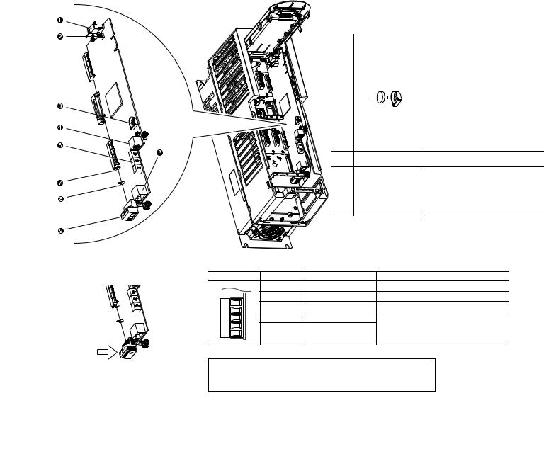
Fig. 1 — Allen Bradley Data Nameplate
A19-1830
IDENTIFYING DRIVE COMPONENTS
A chiller control schematic and a VFD schematic are included in Appendix A.
 WARNING
DC bus capacitors retain hazardous voltages after input power has been disconnected. After disconnecting input power, wait five (5) minutes for the DC bus capacitors to discharge and then check the voltage with a voltmeter rated for the DC bus voltage to ensure the DC bus capacitors are discharged before touching any internal components. Failure to observe this precaution could result in severe bodily injury or loss of life.
An isolated multimeter will be needed to measure DC bus voltage and to make resistance checks. The drive’s DC bus capacitors retain hazardous voltages after input power has been disconnected.
711 |
2 |
Opening the VFD Access Door
 WARNING
Before removing the drive enclosure, open access door and verify that the DC bus voltage has dropped to zero by checking the terminals behind the access door. Failure to observe this precaution could result in severe bodily injury or loss of life.
1.Using recommended screwdriver = 6.4 mm (0.25 in.) flat or T20 star, open access door. See Fig. 2.
2.Check to be sure that the voltage between DC+ and DCand from each DC terminal to the chassis is zero before proceeding. See Fig. 3.
Drive Assembly Catalog Number — See Fig. 4 for an example Catalog Number.
Components and Physical Data — The AllenBradley PF755 Frame 6 drive is used for the 230-amp rated application (carrier Part No. 19XRV0230...). See Fig. 5.
The Allen-Bradley PF755 Frame 7 drive is used for the 335-amp and 445-amp rated application (Carrier Part No. 19XVR0335... and 19XVR0445... respectively). See Fig. 6.
See Fig. 7 for the dimensions of Frames 6 and 7.
Fig. 2 — Opening Access Door
A19-1831
1 L1 L2 L3 |
I |
 LOCKOUT/TAGOUT
 O
O
2 |
0V |
|
DC BUS TEST |
DC+ DC– |
|
|
TERMINALS |
0V |
MULTIMETER |
|
LOCATED INSIDE |
|||
|
ACCESS DOOR
A19-1842
21P 1 0248
21P PF755 VFD
Voltage Rating
1– 460 to 480 v, 60 Hz
2– 380 to 415 v, 50 Hz
3– 380 to 400 v, 60 Hz 4– 401 to 439 v, 60 Hz
PF755 Full Load Amp Rating (Maximum Continuous Amps)* 0248 – 248 0361 – 361 0477 – 477
* For Carrier applications, maximum continuous amp ratings are 230, 335, and 445.
Fig. 3 — Check DC Bus Terminals
A19-1814
3 - 3 - 0 - 0 - C
Customer
C – Carrier
Meter Package
0 – No Meter Package
1 – Analog Meter Package
Input Reactor
0 – No Input Reactor
1 – 3% Input Line Reactor
Disconnect/Breaker Options
3 – 65 KAIC Capacity Breaker
4 – 100 KAIC Capacity Breaker
Drive Assembly
3 – Unit Mount NEMA 1 Liquid Cooled
Fig. 4 — Drive Assembly Catalog Number Nomenclature
3

|
|
|
A19- |
|
|
1832 |
|
|
|
LEGEND |
|
NO. |
NAME |
|
DESCRIPTION |
1 |
Power Terminals |
|
R/L1, S/L2, T/L3, U/T1, V/T2, W/T3 |
2 |
PE Grounding Studs |
|
Terminating point to chassis ground |
|
|
for incoming motor shield |
|
|
|
|
|
3 |
DC Bus and Brake |
|
+DC, -DC, BR1, BR2 |
Terminals |
|
|
|
|
|
|
|
4 |
PE-A and PE-B |
|
MOV and CMC Jumper Wires |
5 |
DC+ and DC- |
|
Bus Voltage Test Points |
Fig. 5 — Frame 6 Drive Components
A19-1833 |
LEGEND |
NO. |
NAME |
DESCRIPTION |
1 |
Power Terminals |
R/L1, S/L2, T/L3, U/T1, V/T2, W/T3 |
2 |
PE Grounding Studs |
Terminating point to chassis ground |
|
for incoming motor shield |
|
|
|
|
3 |
DC Bus and Brake |
+DC, -DC, BR1, BR2 |
Terminals |
|
|
|
|
|
4 |
PE-A and PE-B |
MOV and CMC Jumper Wires |
5 |
DC+ and DC- |
Bus Voltage Test Points |
Fig. 6 — Frame 7 Drive Components
4
A19-1834
Fig. 7 — Enclosure Dimensions - Frames 6 and 7
START-UP
 DANGER
Internal components and circuit boards of the drive are live when the drive is connected to incoming power. Coming into contact with this voltage is extremely dangerous and will result in severe personal injury or death.
The motor terminals U, V, W and the DC-link/brake resistor terminals B+/R+, R- are live when the drive is connected to incoming power, even if the motor is not running.
Do not make any connections when the drive is connected to the incoming power.
After having disconnected the drive, wait until the indicators on the keypad go out (if no keypad is attached see the indicator through the keypad base). Wait 5 more minutes before doing any work on drive connections. Do not even open the cover before this time has expired..
Before connecting the drive to the incoming power, make sure that the switchgear enclosure door is closed.
 WARNING
The control I/O-terminals are isolated from the mains potential. However, the relay outputs and other I/O terminals may have a dangerous control voltage present even when the drive is disconnected from incoming power. Coming into contact with this voltage could result in severe personal injury.
 CAUTION
If other than refrigerant cooling is used, before connecting the drive to the incoming power, make sure that the coolant is circulating and has no leaks.
 CAUTION
When working with the Drive Explorer, never use the Rotate function as the motor will immediately start and severe compressor damage could result.
Alternate Wire Lugs — In the case where the incoming power wire size does not fit the standard lug, alternate lugs may be used. See Table 1. Note that lugs rated for a higher current than the circuit breaker may be used.
Table 1 — Wire Lugs
CIRCUIT |
STANDARD |
STANDARD |
ALTERNATE |
ALTERNATE |
|
LUG CABLE |
LUG CABLE |
||||
BREAKER |
ABB LUG |
RANGE |
ABB LUG |
RANGE |
|
|
|
|
|||
65 KAIC |
|
|
|
|
|
(Standard) |
K6TJ |
(3) 2/0 - 400 |
K6TH |
(2) 250 - 500 |
|
100 KAIC |
MCM |
MCM |
|||
|
|
||||
(Optional) |
|
|
|
|
Verify Installation — Record the following job information:
1.Job Name
2.Job Number
3.City
4.State
5.Zip Code
Record the following nameplate information:
1.From the Allen-Bradley nameplate (Fig. 1) located inside the VFD enclosure:
a.Allen-Bradley ID or CAT NO.
b.Allen-Bradley Serial Number
c.Carrier Part Number
2.From the machine nameplete (Fig. 8) located inside the VFD enclosure:
a.Chiller Serial Number
b.Chiller Model
c.Motor rated load amps
d.Motor nameplate rpm
e.Motor nameplate kW
f.Motor nameplate voltage
g.IPWM (pulse width modulation) frequency
h.Voltage
3.From the drive module label (Fig. 9) located on the drive module:
a.Model or Cat. Number
b.Serial Number
4.From the ICVC control panel screen:
a.Carrier Part Number and Revision
b.ICVC Software Number
Rockwell PowerFlex 750 drive start-up must be registered on the Rockwell website. Rockwell Registration site URL: http://www.automation.rockwell.com/warp/default.asp
5
a19-
1846
A United Technologies Company
MODEL NUMBER
SERIAL NUMBER
MACHINE NAMEPLATE SUPPLY DATA
VOLTS/PHASE/HERTZ
LOCKED ROTOR AMPS
OVERLOAD TRIP AMPS
MAX FUSE/CIRCUIT BREAKER SIZE
MIN SUPPLY CIRCUIT AMPACITY
MACHINE ELECTRICAL DATA
MOTOR NAMEPLATE VOLTAGE
COMPRESSOR 100% SPEED
RATED LINE VOLTAGE
RATED LINE AMPS
RATED LINE KILOWATTS
MOTOR RATED LOAD KW
MOTOR RATED LOAD AMPS
MOTOR NAMEPLATE AMPS
MOTOR NAMEPLATE RPM
MOTOR NAMEPLATE KW
INTERTER PWM FREQUENCY
SAFETY CODE CERTIFICATION
THE COMPRESSOR MOTOR CONTROLLER AND OVERLOAD PROTECTION MUST BE
IN ACCORDANCEWITH CARRIER SPECIFICATION Z-420.
19XV05008701 REV. 3 
Fig. 8 — Machine Nameplate
a19-
1924
Fig. 9 — Drive Module Label
Configure the VFD — All configurations required by the VFD are supplied by the ICVC through the VFD Gateway. Any configuration changes necessary and possible are made on the ICVC screens. A complete set of configurations is transmitted to the VFD each time the controls are powered up.
The following is from the 19XRV PIC III ICVC screen. Parameters in italics are to be entered or confirmed at start-up. Parameters in bold are to be changed only after consulting with Carrier service engineering. See Table 2.
Table 2 — VFD Configurations
PARAMETER |
DEFAULT VALUE |
|
Motor Nameplate Voltage |
460 |
|
Compressor 100% Speed |
|
|
Line Freq=60 Hz? (No=50) |
Yes |
|
Rated Line Voltage* |
460 |
|
Rated Line Amps* |
200 |
|
Rated Line Kilowatts * |
100 |
|
Motor Rated Load kW* |
100 |
|
Motor Rated Load Amps* |
200 |
|
Motor Nameplate Amps |
100 |
|
Motor Nameplate RPM |
3456 |
|
Motor Nameplate KW |
100 |
|
Inverter PWM Frequency (0 = 4 kHz, 1 = |
1 |
|
2 kHz) |
||
|
||
Skip Frequency 1 (Hz) |
102.0 |
|
Skip Frequency 2 (Hz) |
102.0 |
|
Skip Frequency 3 (Hz) |
102.0 |
|
Skip Frequency Band Line (Hz) |
0.0 |
|
Voltage % Imbalance |
10 |
|
Line Volt Imbalance Time (sec) |
10 |
|
Line Current % Imbalance |
40 |
|
Line Current Imbal Time (sec) |
10 |
|
Motor Current % Imbalance |
40 |
|
Motor Current Imbal Time |
10 |
|
Increase Ramp Time (sec) |
30 |
|
Decrease Ramp Time (sec) |
30 |
|
Single Cycle Dropout (DSABLE/ENABLE) |
DSABLE |
* Parameters marked with an * are not downloadable to the VFD but are used in other calculations and algorithms in the ICVC.
NOTES:
1.Parameters in italics are to be entered or confirmed at start-up.
2.Parameters in bold are to be changed only after consultation with service engineering.
Commissioning the Unit — The commission procedure is as follows:
1.If the chiller has been stored outdoors, allow at least 24 hours room temperature stabilization prior to commissioning. Ensure any condensation that occurs as a result of the ambient temperature is allowed to evaporate.
2.Enter parameters in the VFD_CONF screen.
3.Install surge suppression devices if required.
4.Review the power wiring and grounding to ensure that it has been properly connected.
5.Visually examine the inside of the drive enclosure to:
a.Look for signs of corrosion or moisture residue.
b.Remove any dirt or debris.
c.Make sure all vents are clear.
6.Apply power to the drive and take thermal measurements of the capacitor bank and power connections. Do this again before start-up.
7.Measure and record the incoming line voltage. Line-to- line voltages should be balanced within 3% as calculated by Rockwell’s procedure below:
Measure voltages phase-to-phase and phase-to-ground.
6
Vmax = Maximum measured phase-to-phase voltage (A to B, B to C, C to A)
Vmin = Minimum measured phase-to-phase voltage Imbalance Calculation Formula
Vavg |
= |
(VAB + VBC + VCA) |
|
|
3 |
Imbalance % |
= |
(Vmax – Vmin) x 100 |
|
|
Vavg |
8.Take a final thermal measurement of the capacitor bank and power after finalizing the installation to ensure all connections are good.
9.If a ground fault occurs, then do the following:
a.Check for a ground in the motor or motor wiring.
b.Check for damage to wiring insulation and that wiring is dry.
c.Verify the motor wiring is separated from ground and there is no connection between phases.
d.Check for failed IGBTs.
10.If an Overcurrent fault occurs, then do the following:
a.Check for excessive load and verify load limit settings on the ICVC.
b.Check motor and wiring insulation.
c.Check parameter settings on VFD_CONF screen in the ICVC.
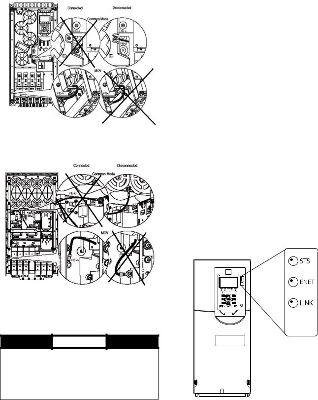
Check Internal Jumpers — On the Main VFD Control board there are two jumpers labeled J1 HARDWARE ENABLE and J2 SAFETY ENABLE. J1 should be removed and J2 should be in place. See Fig. 10.
There are two jumper wires that connect a particular terminal to chassis ground. The MOV and AC EMI jumper should be connected to the PE-A terminal. The COMMON MODE CAPACITORS to GROUND jumper should be connected to a standoff rather than the PE-B terminal.
Use the recommended tools as follows when connecting jumper wires in Frame 6 and in Frame 7:
•Recommended torque (screws and nuts) = 1.36 N·m (120.0 lb·in)
•Recommended hex socket = 7 mm
•Recommended screwdriver = T20 star type
See Fig. 11A and Fig. 11B for the correct positions of the jumpers.
|
|
LEGEND |
NO. |
NAME |
DESCRIPTION |
1 |
HIM Connector |
DPI Port 1 (HIM Cradle) connection. |
2 |
Fan Connector |
Power supply for internal cooling fan |
|
(Frames 2 & 3). |
|
|
|
|
|
Battery |
User installed CR1220 lithium coin cell |
|
Receptacle |
battery provides power to the Real Time |
3 |
|
Clock (Optional, not supplied). |
|
|
|
|
|
|
4 |
DPI Port 2 |
Cable connection for handheld and |
|
remote HIM options. |
|
|
|
|
5 |
Embedded EtherNet/ |
Rotary switches for setting lowest octet |
IP Address Selectors |
of EtherNet address (forces address to |
|
|
|
192.168.1.xxx). |
6Embedded EtherNet/ Network cable connection. IP Connector
7 |
Jumper J2 SAFETY |
Safety enable jumper. Removed when |
|
safety option is installed. |
|
|
|
|
8 |
Jumper J1 ENABLE |
Hardware enable jumper. Removed |
|
when a hardware enable configuration is |
|
|
|
utilized. |
9 |
TB1 |
I/O terminal block. |
a19-1921
|
|
TB1 I/O Terminal Designations |
||
FIXED I/O |
TERMINAL |
NAME |
DESCRIPTION |
|
|
Di 0ac |
Digital Input 120V AC |
Connections for AC power supply. |
|
Di 0ac |
Di C |
Digital Input Common |
Digital input common |
|
Di 0dc |
Digital Input 24V DC |
Connections for DC power supply. |
||
Di C |
||||
Di 0dc |
+24V |
+24 Volt Power |
Connections for drive supplied 24V power. |
|
+24V |
|
24 Volt Common |
|
|
|
24VC |
|
||
24VC |
|
|
||
IMPORTANT: Wiring to pluggable terminal block connectors should be supported by wire ties or other means to help prevent unintentional disconnection
Fig. 10 — PF755 Main Control Board
7
A19-1835
Fig. 11A — Jumper Wire Locations — Frame 6
A19-1836
Fig. 11B — Jumper Wire Locations — Frame 7
SERVICE
 WARNING
DC bus capacitors retain hazardous voltages after input power has been disconnected. After disconnecting input power, wait five (5) minutes for the DC bus capacitors to discharge and then check the voltage with a voltmeter to ensure the DC bus capacitors are discharged before touching any internal components. Failure to observe this precaution could result in severe bodily injury or loss of life.
Troubleshooting the Drive — The drive can display two kinds of error codes on the ICVC called the Alert and Alarm codes. These codes signal a problem detected during self tuning or drive operation. Alert and Alarm codes are located in the 19XRV Start-Up, Operation and Maintenance Instructions. Note the following differences between Carrier and Allen-Bradley terminology:
•A warning message on the ICVC is an ALERT.
•The same warning viewed with Rockwell Drive Explorer is a VFD ALARM.
•A failure resulting in a shutdown is seen as an ALARM on the ICVC and as a VFD FAULT when viewed with Drive Explorer.
CONDITION CODES
ICVC ALERT |
= |
VFD ALARM |
ICVC ALARM |
= |
VFD FAULT |
See Tables 3-6 and Fig. 12.
ICVC ALERT CODES — An alert condition is indicated by a message at the top of the ICVC default screen. In addition, an exclamation point (!) will appear next to any affected point on an ICVC display screen. The drive will continue to operate during the alert condition. Investigate the cause of the alert to ensure it does not lead to a fault condition. The alert code will automatically be cleared from the ICVC when the condition causing the alert no longer exists. See Table 4.
ICVC ALARM CODES — An alarm condition is also indicated by a message at the top of the ICVC default screen. If an alarm occurs, the drive coasts to stop. The STS (status) light on the drive will turn from Green to Red or Yellow (see Table 3). The detected fault message is maintained on the display until it is cleared by pressing the RESET softkey. See Table 5.
TEST EQUIPMENT NEEDED TO TROUBLESHOOT — An isolated multimeter adequately rated for the DC bus voltage will be needed to measure DC bus voltage and to make resistance checks. Note that dedicated troubleshooting test points are not provided.
 Allen-Bradley
7 |
8 |
9 |
4 |
5 |
6 |
1 |
2 |
3 |
|
|
A1
9-
1815
Fig. 12 — Drive Status Indicator
8
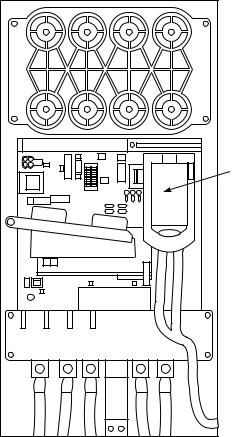
Table 3 — Drive Status Indicator Descriptions
NAME |
COLOR |
STATE |
DESCRIPTION |
|
|
Green |
Flashing |
Drive ready but not running, and no faults are present. |
|
|
|
Steady |
Drive running, no faults are present. |
|
|
Yellow |
Flashing |
Drive is not running. A type 2 (non-configurable) alarm condition exists and the |
|
|
|
|
drive cannot be started. |
|
|
|
Steady |
Drive is not running, a type 1 alarm condition exists. The drive can be started. |
|
STS (Status) |
Red |
Flashing |
A major fault has occurred. Drive cannot be started until fault condition is |
|
|
|
cleared. |
||
|
|
Steady |
A non-resettable fault has occurred. |
|
|
Red/Yellow |
Flashing Alternately |
A minor fault has occurred. When running, the drive continues to run. System is |
|
|
|
|
brought to a stop under system control. Fault must be cleared to continue. Use |
|
|
|
|
parameter 950 [Minor Flt Config] to enable. If not enabled, acts like a major |
|
|
|
|
fault. |
|
|
Green/Red |
Flashing Alternately |
Drive is flash updating. |
|
|
None (Unlit) |
Off |
Adapter and/or network is not powered, adapter is not properly connected to |
|
|
|
|
the network, or adapter needs an IP address. |
|
|
Red |
Flashing |
An EtherNet/IP connection has timed out. |
|
ENET |
|
Steady |
Adapter failed the duplicate IP address detection test. |
|
Red/Green |
Flashing Alternately |
Adapter is performing a self-test. |
||
|
||||
|
Green |
Flashing |
Adapter is properly connected but is not communicating with any devices on |
|
|
|
|
the network. |
|
|
|
Steady |
Adapter is properly connected and communicating on the network. |
|
|
None (Unlit) |
Off |
Adapter is not powered or is not transmitting on the network. |
|
LINK |
Green |
Flashing |
Adapter is properly connected and transmitting data packets on the network. |
|
|
|
Steady |
Adapter is properly connected but is not transmitting on the network. |
NOTES:
1.A Type 1 alarm indicates that a condition exists. Type 1 alarms are user configurable.
2.A Type 2 alarm indicates that a configuration error exists and the drive cannot be started. Type 2 alarms are not configurable.
VERIFYING THAT DC BUS CAPACITORS ARE DISCHARGED — The drive’s DC bus capacitors retain hazardous voltages after input power has been disconnected. Perform the following steps before touching any internal components:
1.Turn off and lock out input power. Wait five minutes.
2.Verify that there is no voltage at the drive’s input power terminals.
3.Measure the DC bus potential with a voltmeter while standing on a non-conductive surface and wearing insulated gloves (1000 V). Measure the DC bus potential. See Fig. 5 for the 248-amp drive and Fig. 6 for the 361 and 477-amp drives. The voltage between DC+ and DC-, and from each DC terminal to the chassis must be zero before proceeding.
4.Once the drive has been serviced, reapply input power.
HIGH TEMPERATURE ALARMS — Coolant flow through the cold plate is controlled by an orifice in the refrigerant line leaving the cold plate. The orifice looks like one of the O-ring face seal connectors and in fact is used as one of the connections on the coolant tubing. The difference is that the passage through the fitting is 0.375 in. (9.5 mm). If the orifice is present and condenser liquid flow is present, the liquid will flash to cooler temperature at the orifice. This temperature difference is great enough to be easily felt.
MAIN CONTROL BOARD (MCB) COMPONENTS — Figure 13 shows the drive module with the cover removed. To access the control boards, loosen the screw on the face of the keypad mount and swing the keypad mount upward.
The components on the main control board (MCB) are shown in Fig. 14. Note the location of the terminals labeled MCB I/O. The high pressure switch is wired to these terminals as shown in Fig. 15. In the event of a high condenser pressure alarm, the connections at these terminals should be checked and tightened if necessary.
A typical wiring schematic is shown in Appendix A.
SWING UP KEY PAD
MOUNT TO ACCESS
CONTROL BOARDS
a19-1843
Fig. 13 — Drive Module with Cover Removed
9
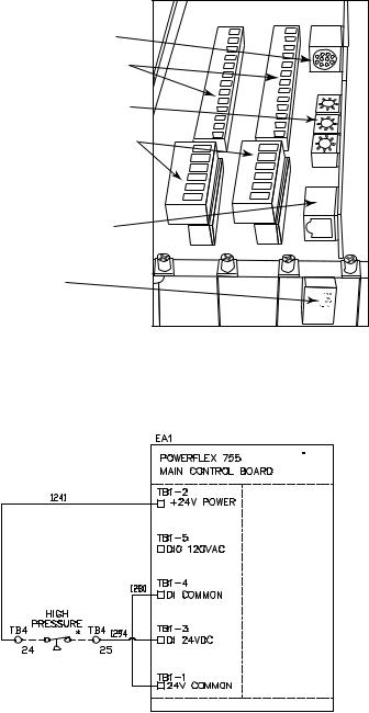
DPI PORT 02 (COMPUTER PORT)
DIGITAL INPUT TERMINAL BLOCKS (SLOTS 04 & 05)
ETHERNET/IP ADDRESS SWITCHES
DIGITAL OUTPUT TERMINAL BLOCKS (SLOTS 04 & 05)
EMBEDDED ETHERNET/IP PORT
MCB I/O TERMINALS (AUX FAULT /
HIGH PRESSURE FAULT / ENABLE INPUT)
Fig. 14 — MCB (Main Control Board) Components
a19-1844
*Located outside of starter; connected by field wiring.
Fig. 15 — High Pressure Switch Wiring
a19-1925
10
Table 4 — ICVC Alert Codes
PRE-START ALERTS: These alerts only delay start-up. When alert is corrected, the start-up will continue. No reset is necessary.
ICVC FAULT |
PRIMARY |
SECONDARY |
PRIMARY CAUSE |
ADDITIONAL CAUSE/REMEDY |
|
STATE |
MESSAGE |
MESSAGE |
|||
|
|
||||
100 |
PRESTART |
STARTS LIMIT |
100 Excessive compressor starts |
Depress the RESET softkey if additional start |
|
|
ALERT |
EXCEEDED |
(8 in 12 hours). |
is required. Reassess start-up requirements. |
|
101 |
PRESTART |
HIGH BEARING |
101 Comp Thrust Brg Temp [VALUE] |
Check oil heater for proper operation. |
|
|
ALERT |
TEMPERATURE |
exceeded limit of [LIMIT]*. |
Check for low oil level, partially closed oil sup- |
|
|
|
|
|
ply valves, clogged oil filters. |
|
|
|
|
|
Check the sensor wiring and accuracy. |
|
|
|
|
|
Check Comp Thrust Brg Alert setting in |
|
|
|
|
|
SETUP1 screen. |
|
102 |
PRESTART |
HIGH MOTOR |
102 Comp Motor Winding Temp |
Check motor sensors for wiring and accuracy. |
|
|
ALERT |
TEMPERATURE |
[VALUE] exceeded limit of [LIMIT]*. |
Check motor cooling line for proper operation, |
|
|
|
|
|
or restrictions. |
|
|
|
|
|
Check for excessive starts within a short time |
|
|
|
|
|
span. |
|
|
|
|
|
Check Comp Motor Temperature Override |
|
|
|
|
|
setting in SETUP1 screen. |
|
103 |
PRESTART |
HIGH |
103 Comp Discharge Temp [VALUE] |
Allow discharge sensor to cool. |
|
|
ALERT |
DISCHARGE |
exceeded limit of [LIMIT]*. |
Check sensor wiring and accuracy. |
|
|
|
TEMP |
|
Check for excessive starts. |
|
|
|
|
|
Check Comp Discharge Alert setting in |
|
|
|
|
|
SETUP1 screen. |
|
104 |
PRESTART |
LOW |
104 Evaporator Refrig Temp [VALUE] |
Check transducer wiring and accuracy. |
|
|
ALERT |
REFRIGERANT |
exceeded limit of [LIMIT]*. |
Check for low chilled fluid supply |
|
|
|
TEMP |
|
temperatures. |
|
|
|
|
|
Check refrigerant charge. |
|
|
|
|
|
Check Refrig Override Delta T in SETUP1 |
|
|
|
|
|
screen. |
|
105 |
PRESTART |
LOW OIL |
105 Oil Sump Temp [VALUE] |
Check oil heater contactor/relay and power. |
|
|
ALERT |
TEMPERATURE |
exceeded limit of [LIMIT]*. |
Check oil level and oil pump operation. |
|
106 |
PRESTART |
HIGH |
106 Condenser Pressure [VALUE] |
Check transducer wiring and accuracy. |
|
|
ALERT |
CONDENSER |
exceeded limit of [LIMIT]*. |
Check for high condenser water |
|
|
|
PRESSURE |
|
temperatures. |
|
|
|
|
|
Check high condenser pressure switch wiring. |
|
107 |
PRESTART |
LOW LINE |
107 Percent Line Voltage [VALUE] |
Check voltage supply. |
|
|
ALERT |
VOLTAGE |
exceeded limit of [LIMIT]*. |
Check voltage transformers and switch gear. |
|
|
|
|
|
Consult power utility if voltage is low. |
|
108 |
PRESTART |
HIGH LINE |
108 Percent Line Voltage [VALUE] |
Check voltage supply. |
|
|
ALERT |
VOLTAGE |
exceeded limit of [LIMIT]*. |
Check power transformers. |
|
|
|
|
|
Consult power utility if voltage is high. |
|
109 |
PRESTART |
GUIDE VANE |
109 Actual Guide Vane Pos |
Press STOP button on ICVC and perform |
|
|
ALERT |
CALIBRATION |
Calibration Required Before Startup. |
Guide Vane Calibration in Controls Test |
|
|
|
|
|
screen. |
|
|
|
|
|
Check guide vane actuator feedback |
|
|
|
|
|
potentiometer. |
|
110 |
PRESTART |
HIGH |
110 Rectifier Temperature [VALUE] |
Check that VFD refrigerant isolation valves |
|
|
ALERT |
RECTIFIER |
exceeded limit of [LIMIT]*. |
are open. |
|
|
|
TEMP |
|
Check VFD refrigerant cooling solenoid and |
|
|
|
|
|
refrigerant strainer. |
|
|
|
|
|
Check for proper VFD cooling fan operation |
|
|
|
|
|
and blockage. |
|
111 |
PRESTART |
HIGH |
111 Inverter Temperature [VALUE] |
Check that VFD refrigerant isolation valves |
|
|
ALERT |
INVERTER |
exceeded limit of [LIMIT]*. |
are open. |
|
|
|
TEMP |
|
Check VFD refrigerant cooling solenoid and |
|
|
|
|
|
refrigerant strainer. |
|
|
|
|
|
Check for proper VFD cooling fan operation |
|
|
|
|
|
and blockage. |
*[LIMIT] is shown on the ICVC as temperature, pressure, voltage, etc., predefined or selected by the operator as an override or an alert. [VALUE] is the actual pressure, temperature, voltage, etc., at which the control tripped.
11
Table 4 — ICVC Alert Codes (cont)
NORMAL RUN WITH OVERRIDES
ICVC FAULT |
PRIMARY |
SECONDARY |
PRIMARY CAUSE |
ADDITIONAL CAUSE/REMEDY |
|
STATE |
MESSAGE |
MESSAGE |
|||
|
|
||||
120 |
RUN CAPACITY |
HIGH CONDENSER |
120 Condenser Pressure |
Check condenser water pump operation. |
|
|
LIMITED |
PRESSURE |
[VALUE] exceeded limit of |
Check for high condenser water temperatures or |
|
|
|
|
[LIMIT]*. |
low flow rate. Verify that isolation valves are |
|
|
|
|
|
open. |
|
|
|
|
|
Check Cond Press Override setting in SETUP1. |
|
121 |
RUN CAPACITY |
HIGH MOTOR |
121 Comp Motor Winding |
Check for closed valves or restriction in motor |
|
|
LIMITED |
TEMPERATURE |
Temp [VALUE] exceeded |
cooling lines. |
|
|
|
|
limit of [LIMIT]*. |
Check for closed refrigerant isolation valves. |
|
|
|
|
|
Check Comp Motor Temp Override setting in |
|
|
|
|
|
SETUP1. |
|
122 |
RUN CAPACITY |
LOW EVAP REFRIG |
122 Evaporator Refrig |
Check refrigerant charge. |
|
|
LIMITED |
TEMP |
Temp [VALUE] exceeded |
Check that optional cooler liquid line isolation |
|
|
|
|
limit of [LIMIT]*. |
valve is fully open. |
|
|
|
|
|
Check for excessive condenser flow or low |
|
|
|
|
|
chilled water flow. |
|
|
|
|
|
Check for low entering cooler temperature. |
|
|
|
|
|
Check that condenser inlet and outlet water |
|
|
|
|
|
nozzles are piped correctly. |
|
|
|
|
|
Check for waterbox division plate gasket bypass. |
|
123 |
RUN CAPACITY |
HIGH COMPRESSOR |
123 Surge Prevention |
Check for high condenser water temperature or |
|
|
LIMITED |
LIFT |
Override: Lift Too High For |
low suction temperature. |
|
|
|
|
Compressor |
Check for high Evaporator or Condenser |
|
|
|
|
|
approaches. |
|
|
|
|
|
Check surge prevention parameters in |
|
|
|
|
|
OPTIONS screen. |
|
124 |
RUN CAPACITY |
MANUAL GUIDE VANE |
124 Run Capacity Limited: |
Target Guide Vane Position has been forced in |
|
|
LIMITED |
TARGET |
Manual Guide Vane Target. |
the COMPRESS screen. Select and RELEASE |
|
|
|
|
|
force to return to normal (automatic) operation. |
|
125 |
RUN CAPACITY |
LOW DISCHARGE |
No Alert message. |
Check for oil loss or excess refrigerant charge. |
|
|
LIMITED |
SUPERHEAT |
|
Verify that the valves in the oil reclaim lines are |
|
|
|
|
|
open. |
|
126 |
RUN CAPACITY |
HIGH RECTIFIER TEMP |
126 Rectifier Temperature |
Check Rectifier Temp Override in SETUP1 |
|
|
LIMITED |
|
[VALUE] exceeded limit of |
screen. |
|
|
|
|
[LIMIT]*. |
Check that VFD refrigerant isolation valves are |
|
|
|
|
|
open. |
|
|
|
|
|
Check VFD refrigerant cooling solenoid. |
|
|
|
|
|
Check for proper VFD cooling fan operation and |
|
|
|
|
|
blockage. |
|
127 |
RUN CAPACITY |
MANUAL SPEED |
No Alert message. |
Chiller is not in automatic temperature control. |
|
|
LIMITED |
CONTROL |
|
|
|
128 |
RUN CAPACITY |
HIGH INVERTER TEMP |
128 Inverter Temperature |
Check Inverter Temp Override in SETUP1 |
|
|
LIMITED |
|
[VALUE] exceeded limit of |
screen. |
|
|
|
|
[LIMIT]*. |
Check that VFD refrigerant isolation valves are |
|
|
|
|
|
open. |
|
|
|
|
|
Check VFD refrigerant cooling solenoid. |
|
|
|
|
|
Check for proper VFD cooling fan operation and |
|
|
|
|
|
blockage. |
*[LIMIT] is shown on the ICVC as the temperature, pressure, voltage, etc., set point predefined or selected by the operator as an override, alert, or alarm condition. [VALUE] is the actual pressure, temperature, voltage, etc., at which the control tripped.
12
 Loading...