


Lifestyle® V-Class™
H O M E T H E A T E R S Y S T E M S
Owner’s Guide
Guía de usario
Notice d’utilisation
English |
TAB 2 |
TAB 3 |
TAB |
TAB |
TAB 6 |
TAB |
English |
|
|
|
|
|
|
|
|
SAFETY INFORMATION
Please read this Owner’s Guide
Please take the time to follow the instructions in this guide carefully. It will help you set up and operate your system properly and enjoy its advanced features. Please save this guide for future reference.
The lightning flash with arrowhead symbol within an equilateral triangle alerts the user to the presence of uninsulated, dangerous voltage within the system enclosure that may be of sufficient magnitude to constitute a risk of electrical shock.
The exclamation point within an equilateral triangle, as marked on the system, is intended to alert the user to the presence of important operating and maintenance instructions in this owner’s guide.
 WARNING: To reduce the risk of fire or electrical shock, do not expose the product to rain or moisture.
 WARNING: The apparatus shall not be exposed to dripping or splashing, and objects filled with liquids, such as vases, shall not be placed on the apparatus. As with any electronic products, use care not to spill liquids into any part of the system. Liquids can cause a failure and/or a fire hazard.
 WARNING: No naked flame sources, such as lighted candles, should be placed on the apparatus.
 WARNING: To prevent electric shock, match the wide blade of the line cord plug to the wide slot of the AC (mains) receptacle. Insert fully.
ii

English |
TAB |
TAB 6Italiano |
TAB 5 |
TAB 4 |
TAB 3 |
TAB 2 |
English |
|
|
|
|
|
|
|
|
SAFETY INFORMATION
CAUTION: Make no modifications to the system or accessories. Unauthorized alterations may compromise safety, regulatory compliance, and system performance.
Class B emissions
This Class B digital apparatus meets all requirements of the Canadian Interference-Causing Equipment Regulations (Canada only).
This product conforms to the EMC Directive 2004/108/EC and to the Low Voltage Directive 2006/95/EC. The remote control conforms to the RTTE Directive 99/5/EC. The complete Declaration of Conformity can be found at www.Bose.com/static/compliance/index.html.
Please dispose of used batteries properly, following  any local regulations. Do not incinerate.
Note: The product label is located on the bottom of the product.
Note: Where the mains plug or appliance coupler is used as the disconnect device, such disconnect device shall remain readily operable.
Note: The product must be used indoors. It is neither designed nor tested for use outdoors, in recreation vehicles, or on boats.
Note: This product is intended to be used only with the power supply provided.
Additional safety information
See the additional instructions on the Important Safety Instructions sheet (North America only) enclosed in the shipping carton.
For Your Records
Serial numbers are located on the bottom of the media center and the connection panel of the Acoustimass® module.
Serial numbers: Media center:________________________ Acoustimass module:___________________________
Dealer name:__________________________ Dealer phone:_____________________ Purchase date:____________
Bose recommends that you keep your sales slip and a copy of your product registration card together with this guide.
Be sure to fill out your product registration card and mail it to Bose.
Doing so is the only way to ensure that you will receive future software updates by mail.
iii

TAB |
TAB |
TAB 6Italiano |
TAB 5 |
TAB 4 |
TAB 3 |
TAB 2 |
English |
|
|
|
|
|
|
|
|
TABLE OF CONTENTS
INSTALLATION .......................................... |
2 |
Welcome .................................................................. |
2 |
Your system features: ........................................... |
2 |
Setup assistance ...................................................... |
2 |
Setup Guide .......................................................... |
2 |
Setup and Demonstrations DVD........................... |
3 |
This User Guide .................................................... |
3 |
First Power-Up ......................................................... |
4 |
What to do next .................................................... |
4 |
Tailoring the sound to your room ............................. |
6 |
Carton inventory ....................................................... |
8 |
System parts......................................................... |
8 |
Cables and accessories........................................ |
9 |
Placing the media center and display .................... |
10 |
Placing the cube speakers ..................................... |
10 |
Placing the center speaker ................................. |
11 |
Placing the front left and right speakers ............. |
12 |
Placing the rear speakers ................................... |
12 |
Placing the Acoustimass® module ......................... |
12 |
Making antenna connections ................................. |
14 |
FM antenna connection ...................................... |
14 |
AM antenna connection...................................... |
14 |
Cable radio as an option..................................... |
14 |
Installing the TV on/off sensor ............................... |
15 |
Using a SCART adapter (Europe only) ................... |
17 |
Connecting the audio from your TV ....................... |
18 |
Using the IR emitter ............................................... |
20 |
CONTROLS AND INDICATORS ................... |
22 |
The display ............................................................. |
22 |
The remote control ................................................. |
22 |
OPERATION .......................................... |
30 |
Watching TV ........................................................... |
30 |
Setting up the Lifestyle remote to |
|
control the TV...................................................... |
30 |
Selecting the TV screen shape ........................... |
31 |
Setting the audio delay compensation ............... |
31 |
Changing the HDMI Image View......................... |
31 |
Controlling a cable or satellite box ......................... |
32 |
Programming the Bose remote to |
|
turn the cable or satellite box on or off............... |
32 |
Using the remote to change channels ................ |
33 |
Changing the HDMI Image View......................... |
33 |
About the HDMI video resolution........................ |
33 |
iv

English |
TAB 2 |
TAB 3 |
TAB |
TAB |
TAB 6 |
TAB |
TAB |
|
|
|
|
|
|
|
|
TABLE OF CONTENTS
Controlling DVD playback ..................................... |
34 |
Programming the Lifestyle® remote to |
|
control the DVD player....................................... |
34 |
Changing the HDMI Image View........................ |
35 |
About the HDMI video resolution....................... |
35 |
Setting up to view videotapes ............................... |
36 |
Setting up the Bose remote to control the VCR |
36 |
About the HDMI video resolution....................... |
37 |
Setting up an auxiliary (AUX) source ..................... |
38 |
Setting up the Bose® remote to control the |
|
AUX device......................................................... |
38 |
About the HDMI video resolution....................... |
39 |
Controlling the (HDMI) Image View ....................... |
40 |
Changing the HDMI video resolution .................... |
43 |
Listening to the radio ............................................. |
44 |
Presets ............................................................... |
44 |
Headphone listening ............................................. |
44 |
Settings Options .................................................... |
45 |
System maintenance ............................................. |
50 |
Replacing the remote control batteries.............. |
50 |
Changing remote control switch settings .......... |
50 |
REFERENCE .......................................... |
50 |
Protecting and caring for your system ............... |
52 |
Cleaning the media center ................................. |
53 |
Setting up a second room with sound .................. |
54 |
Bose® link-compatible products make it easy ... |
54 |
Bose® link remote switch settings...................... |
55 |
Troubleshooting ..................................................... |
56 |
Contacting Customer Service ............................... |
60 |
GLOSSARY ............................................ |
61 |
v
TAB |
TAB TAB 6Italiano TAB 5 |
TAB 4 |
TAB 3 |
TAB 2 |
English |
INSTALLATION |
|
|
|
|
|
|
|
|
|
||
|
|
|
|
|
|
Welcome |
|
Setup assistance |
|
|
|
Thank you for choosing a Bose® Lifestyle® V-Class™ home theater system. This elegant and easy-to-use system delivers superior performance for both music and video programming.
Your system features:
•HDMI connectivity
•The ability to up-convert video
•Proprietary ADAPTiQ® audio calibration system, which optimizes system performance to your listening room
•Capability of expanding your system to up to 14 other rooms
The following information is provided to help you set up your system:
Setup Guide
If you haven’t already done so, please refer to the fold-out Setup Guide. It contains all the steps needed to get you through basic system installation, including:
•System placement
•Speaker connections
•Display/media center interconnections
•TV/video connections
•Audio connections
•System power connections
2

English |
TAB 2 |
TAB 3 |
TAB |
TAB |
TAB 6 |
TAB |
TAB |
|
|
|
|
|
|
|
|
INSTALLATION
Setup and Demonstrations DVD
The Setup and Demonstrations DVD is a valuable resource for setup information and content that demonstrates the capability of your Lifestyle® system. We encourage you to view the DVD immediately after you set up your Lifestyle® system and connect your DVD player using the Setup Guide. The setup DVD:
•Provides instructions for optimizing speaker placement
•Explains the importance of running the ADAPTiQ® audio calibration system
•Demonstrates the capabilities of your Lifestyle® system
This User Guide
This User Guide shows you how to complete your system setup, and get the most out of your system. The following information is provided in this user guide:
•ADAPTiQ audio calibration system
Shows how to initiate the ADAPTiQ audio calibration system so that your Lifestyle® system can be calibrated to produce the best sound possible in your listening space.
•Speaker placement
Diagrams and explains how to place your speakers to get the best possible sound.
•Antenna connections
Illustrates how to connect the AM and FM antennas.
•TV sensor setup
Shows how to enable the TV to turn on when a video source (DVD, VCR, etc.) is selected.
•TV audio out connections
Explains how to connect audio from your TV so that you can hear audio from camcorders, game consoles, etc.
•Display and remote control buttons
Details the functions of buttons on the display and remote control.
•Remote control setup
Shows how to set up the remote to control devices.
3
TAB |
TAB |
TAB 6Italiano |
TAB 5 |
TAB 4 |
TAB 3 |
TAB 2 |
English |
|
|
|
|
|
|
|
|
INSTALLATION
First Power-Up
After you connect your Lifestyle® system to your TV and DVD player using the Setup Guide, you are ready to apply power.
1.Turn on the TV and Lifestyle® system.
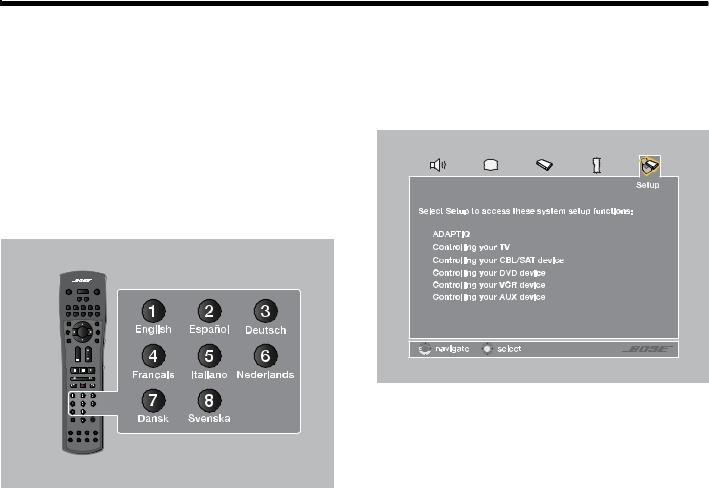
The first time you apply power to your Lifestyle® system, you are guided through a sequence of menus. The first menu displayed on the TV (see Figure 1) directs you to choose the system language.
2.Select a language by pressing the corresponding numeric key on the remote control.
The Setup menu appears as shown in Figure 2.
Figure 2 System menu Setup tab.
Figure 1 Lifestyle® language menu.
4

English |
TAB 2 |
TAB 3 |
TAB |
TAB |
TAB 6 |
TAB |
TAB |
|
|
|
|
|
|
|
|
INSTALLATION
What to do next
The first time the System menu Setup tab displays, you can take one of the following actions:
•If you are confident that your speakers are correctly wired and placed, and that you can understand and navigate the Setup menu, continue using it. See “Operation” beginning on page 30 for more information on using the Setup menu.
•If you would rather be guided through the setup process by the Bose® Setup and Demonstrations DVD, do the following:
The Setup and Demonstrations DVD should begin playing. If not, press the PLAY button on the DVD remote control. Follow the instructions on the DVD. When you are finished with the Setup and Demonstrations DVD, see “Operation” beginning on page 30 for more information on using the Setup menu.
1.Exit the System menu by pressing  on the Lifestyle® remote.
2.Select the DVD player by pressing  on the Lifestyle® remote.
3.Turn your DVD player on and insert the Bose®
Setup and Demonstrations DVD.
5
TAB |
TAB |
TAB 6Italiano |
TAB 5 |
TAB 4 |
TAB 3 |
TAB 2 |
English |
INSTALLATION
Tailoring the sound to your room
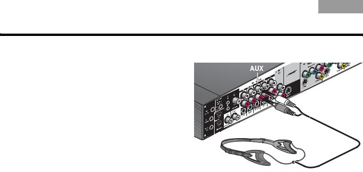
Figure 3 ADAPTiQ headset connection.
The ADAPTiQ® audio calibration system ensures that your Lifestyle® system sounds great. Completing the ADAPTiQ audio calibration system process is the final step of a basic Lifestyle® setup.
If you have already completed the ADAPTiQ audio calibration system process using the Bose® Setup and Demonstrations DVD please go on to the next section, “Carton inventory” on page 8.
A special headset, pictured in Figure 3, can be found in the Essentials kit. The headset, designed to be worn above your ears, contains two miniature microphones that take acoustic measurements during calibration.
You will achieve the best results when the listening room is relatively quiet. Please notify other members of your household that they will hear a series of audio tones.
On the connection panel of the media center (shown in Figure 3), plug the ADAPTiQ headset into the AUX AUDIO IN connectors.
6
English |
TAB 2 |
TAB 3 |
TAB |
TAB |
TAB 6 |
TAB |
TAB |
|
|
|
|
|
|
|
|
INSTALLATION
If you are applying power to your Lifestyle® system for the first time, see “First Power-Up” on page 4.
To run the ADAPTiQ® audio calibration system process, complete the following steps:
1.In the System menu Setup tab (see Figure 4), move to the ADAPTiQ item by pressing the down arrow.
2.Press the right arrow 


 to select Run.
3.To begin the ADAPTiQ audio calibration process, press 


 (Enter).
4.Follow the on-screen directions to complete the process.
Figure 4 System menu Setup tab
7
TAB |
TAB |
TAB 6Italiano |
TAB 5 |
TAB 4 |
TAB 3 |
TAB 2 |
English |
|
|
|
|
|
|
|
|
INSTALLATION
Carton inventory
Now that you have unpacked your system, please save all of the packing materials, which provide the safest means for shipping or transporting.
Note: Now is a good time to locate the serial numbers for your system, on the bottom of the media center and near the connection panel on the Acoustimass® module. For future reference, we suggest that you copy those numbers onto the For Your Records form on page iii.
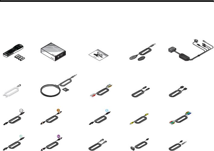
System parts
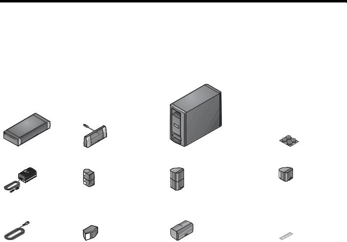
Verify that your system includes the following parts shown in Figure 5.
Figure 5 System parts
Media center |
Display |
Acoustimass® module |
Rubber feet for |
|
|
|
Acoustimass® module |
|
|
|
|
|
|
|
|
|
|
|
|
|
|
|
|
|
|
|
|
|
|
|
|
|
|
|
|
|
|
|
|
|
|
|
|
|
|
|
|
|
|
|
|
|
|
|
|
|
|
|
|
|
|
|
|
|
|
|
|
|
|
|
|
|
|
|
|
|
|
|
|
Power Supply |
Jewel Cube® speakesr (4) |
Direct/Reflecting®cube speakers (4) |
Single Cube speaker (5) |
||||||||
|
|
|
|
(Lifestyle® V30) |
|
(Lifestyle® V20) |
|
(Lifestyle® V10) |
|||
|
|
|
|
|
|
|
|
|
|
|
|
|
|
|
|
|
|
|
|
|
|
|
|
|
|
|
|
|
|
|
|
|
|
|
|
AC Power (2) |
Center channel speaker (1) |
|
(Lifestyle® V30) |
Center channel speaker (1) |
Rubber feet for speakers |
(Lifestyle® V20) |
|
8
English |
TAB 2 |
TAB 3 |
TAB |
TAB |
TAB 6 |
TAB |
TAB |
|
|
|
|
|
|
|
|
INSTALLATION
Cables and accessories
Verify that the items in Figure 6 are supplied. Cables needed to get your system operational are included. Accessories such as antennas, SCART connector
(Europe only), and TV sensor are also included. You may need to acquire other cables or accessories to complete your unique home theater setup as preferred.
Figure 6 Cables and accessories
|
|
|
|
ADAPTiQ® audio calibration |
|
|
|
Remote control and |
Setup and |
TV sensor |
SCART video connector |
||||
|
|
batteries |
system |
Demonstrations DVD |
|
(Europe only) |
|
FM dipole antenna AM loop antenna |
RCA analog audio |
Optical digital audio HDMI digital audio/video |
Left front speaker |
Center front speaker |
Right front speaker |
Composite video |
Component video |
Left rear speaker |
Right rear speaker |
Acoustimass® module IR emitter extender |
IR emitter |
|
|
to media center |
9 |
|
|
|
TAB |
TAB |
TAB 6Italiano |
TAB 5 |
INSTALLATION
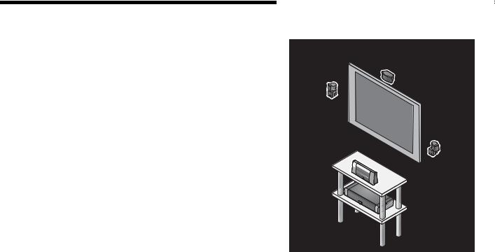
Placing the media center and display
The media center can be placed out of sight behind all of your other A/V components. When placing the media center, ensure that it is close enough to other sources (TV, DVD, VCR, cable or satellite box) to allow for easy cable connections. Check the length of the audio and video cables you will use for these additional components.
CAUTION: Do not block the ventilation openings on either side of the media center. Allow at least two inches on each side.
Place the display module so it is facing out into the room, toward the front of the surface on which it rests, as shown in Figure 7. Allow about two inches of clearance on either side of the display module. Make sure you can clearly see the display module from your listening position.
Bose offers a variety of speaker mounting accessories, including rubber feet, stands, and wall brackets. For more information, or to purchase accessories, contact your local Bose® dealer or visit www.Bose.com. To contact Bose directly, refer to the address list provided in the carton.
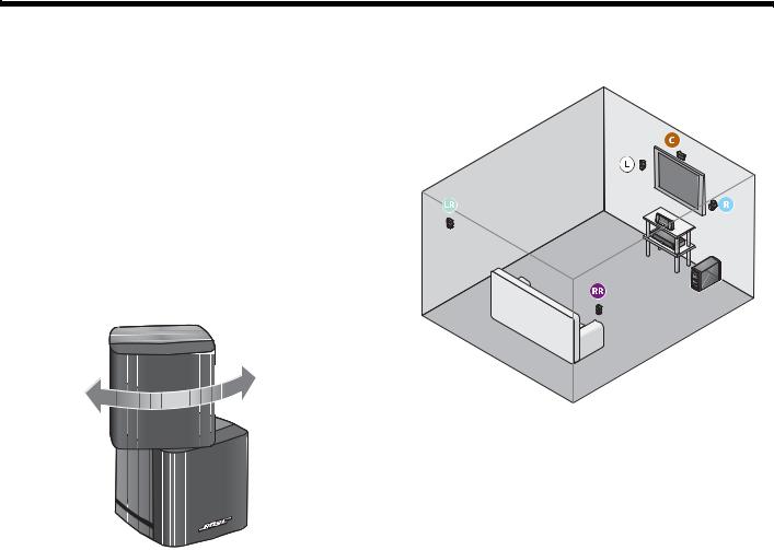
Rotate the top cube of each speaker array toward the wall or another hard surface to create reflected sound.
TAB 4 |
TAB 3 |
TAB 2 |
English |
|
|
|
|
|
|
|
|
|
|
|
|
Figure 7 Typical placement of the Lifestyle® display module

 Display module
10
English |
TAB 2 |
TAB 3 |
TAB |
TAB |
TAB 6 |
TAB |
TAB |
|
|
|
|
|
|
|
|
INSTALLATION
Placing the cube speakers
Figure 8 Approximate speaker locations
When you place your speakers approximately as shown in Figure 8 on page 11, they provide the audio atmosphere of a home theater. You can experiment with speaker placement and orientation to produce the most pleasing sound.
CAUTION: Select a stable and level surface for all speakers. Vibration can cause speakers to move, particularly on smooth surfaces such as marble, glass, or highly polished wood. To reduce the possibility of movement, Bose recommends that you attach the included rubber speaker feet to the bottom of the speakers.
Note: If, after running the ADAPTiQ® audio calibration system, you move one or more speakers to a substantially different location, you should re-run the ADAPTiQ® audio calibration system.
Rotate the top cube toward a wall or other hard surface.
11

TAB |
TAB |
TAB 6Italiano |
TAB 5 |
TAB 4 |
TAB 3 |
TAB 2 |
English |
|
|
|
|
|
|
|
|
INSTALLATION
Placing the center speaker
•Place the center speaker directly above or below the vertical center of the TV screen or as close to that as possible (see Figure 8).
•If you are placing the center speaker directly on the top of your TV, first attach the supplied rubber feet to the bottom surface of the speaker.
•Make sure the 20-foot (6.1-meter) speaker cable can reach from the center speaker to the Acoustimass® module.
Placing the rear speakers
•Position the rear left and right speakers in the back half of your room.
•Make sure each 50-foot (15.2-meter) speaker cable can reach from the speaker to the Acoustimass module.
•Place the speakers at ear height or higher if possible.
•Direct the sound away from the listening positions to maximize the reflected sound.
Placing the front left and right speakers
•Set or mount the front left and right speakers upright and lined up with the horizontal center of the TV screen.
•We recommend a maximum distance of 3 feet (1 meter) from the edge of your TV screen for best results.
•Make sure each 20-foot (6.1-meter) speaker cable can reach from the speaker to the Acoustimass module.
12
English |
TAB 2 |
TAB 3 |
TAB |
TAB |
TAB 6 |
TAB |
TAB |
|
|
|
|
|
|
|
|
INSTALLATION
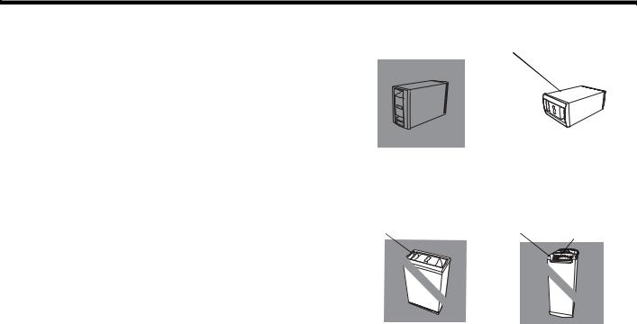
Placing the Acoustimass® module
Attach the four self-adhesive rubber feet to the surface that touches the floor (either of its two sides, its top, or bottom).
Place the Acoustimass® module:
•At the same end of the room as the front speakers.
•At least 18 inches (45 centimeters) from the TV to avoid magnetic interference with the TV image.
•With the front end facing into the room.
•Within reach of the audio input cable, the five speaker cables, and your AC power (mains) outlet.
•Under a table or behind a cabinet, but not where furniture or drapes block any openings on the module.
•On its two sides, its top, or bottom (Figure 9).
Do NOT place the Acoustimass module:
•On its back end or front end (Figure 9).
•Where the ventilation slots for the built-in electronic circuitry are blocked.
•Where it will expose electronic media, such as tapes, to its magnetic field for long periods.
•Where the front end is facing a wall.
Figure 9 Proper and improper Acoustimass module positioning
Top surface |
Side surface |
BEST |
|
|
|
|
|
|
|
ALTERNATE |
|||
For best ventilation, stand the |
|
Place the module on one |
|||
module on its bottom |
|
of its two broad |
|||
surface, |
|
sides. |
|
|
|
Front end |
Back end |
Ventilation |
|||
|
|
|
|
openings |
|
DO NOT |
DO |
NOT |
stand the module on its |
stand the module on its front |
|
slightly curved back end, |
|
grille end. The weight of |
which can cause it to tip |
|
the module can damage |
|
|
the grille. |
13
TAB |
TAB |
TAB 6Italiano |
TAB 5 |
TAB 4 |
TAB 3 |
TAB 2 |
English |
|
|
|
|
|
|
|
|
INSTALLATION
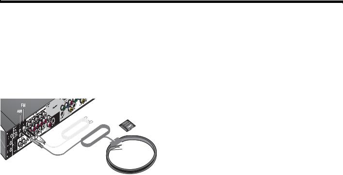
Making antenna connections
The supplied AM and FM antennas connect to the rear panel of the media center (Figure 10).
Note: The FM connector may be used with an outdoor antenna. Before doing this, consult a qualified installer. Follow all safety instructions supplied with the antenna.
Figure 10 Connections for the AM and FM antennas
FM |
AM base |
AM
FM antenna connection
1.Plug the connector on the FM dipole antenna lead into the FM antenna jack.
2.Spread out the antenna arms and change their orientation as needed to get the best FM reception.
3.Keep the antenna as far as possible from the media center, display, and Acoustimass® module.
AM antenna connection
1.Plug the connector on the AM loop antenna lead into the AM antenna jack.
2.Stand the AM antenna on the base or mount the antenna on a wall, following the instructions enclosed with the AM antenna.
3.Keep the antenna as far as possible (at least 20 inches or 50 centimeters) from the media center and display module, and at least 2 feet (60 centimeters) from the Acoustimass module.
Note: AM reception can be adversely affected by a nearby television when it is on. Turn off the TV for best AM reception.
Cable radio as an option
Some cable TV providers make FM radio signals available through the cable service to your home. This cable connects to the FM antenna jack on the back panel of the media center.
For instructions on how to make this connection, contact your cable TV provider.
14
English |
TAB 2 |
TAB 3 |
TAB |
TAB |
TAB 6 |
TAB |
TAB |
|
|
|
|
|
|
|
|
INSTALLATION
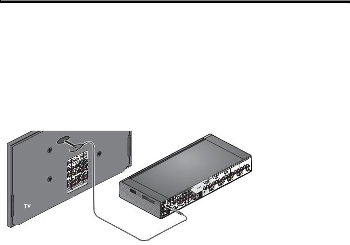
Installing the TV on/off sensor
The TV on/off sensor enables the system to automatically turn on the TV when another video source (DVD, cable/ satellite box, etc.) is selected. If you choose not to use the sensor, you must turn on your TV separately.
For a larger TV, you may want a second person to help as you follow the steps below:
Note: Front projectors with a separate screen may not work with the sensor.
1.Plug the sensor cord connector into the media center TV Sensor connector.
If you are using a SCART adapter, plug the sensor directly into the pass-through connector provided on the adapter (Figure 12 on page 17).
2.Temporarily position the TV on/off sensor on the back of your TV (Figure 11).
Note: DO NOT attach the supplied mounting pad until you have tested and activated the automatic feature as explained below.
Figure 11 TV on/off sensor positioned on the TV
TV sensor
Media center
15

TAB |
TAB |
TAB 6Italiano |
TAB 5 |
TAB 4 |
TAB 3 |
TAB 2 |
English |
|
|
|
|
|
|
|
|
INSTALLATION
3.Using the remote control that came with your TV, turn on your TV.
4.Using the Lifestyle® remote control, press System.
5.To move right to the Setup  menu, press the right arrow


 then press ENTER.
6.Move down to TV Power by pressing the down arrow, then press ENTER.
7.Move up or down to select the proper TV Power option to detect the TV sensor:
•Automatic (for TV models that do not use a European-style SCART connector).
•Euro Connector (for TV models that use a European-style SCART connector).
8.Press ENTER.
Below the highlighted TV Power item is TV Power Status. The value for this item changes from Not Detected to TV On, when the sensor is properly positioned.
Note: It may be helpful to get an assistant for the next step and have one person view the screen, while the other moves the sensor.
9.Hold the sensor against the rear of the TV and slowly move it around until TV Power Status changes from Not Detected to TV On.
10.When the TV Power Status indicates TV On, press Exit to exit the System menu.
This completes sensor activation.
16
English |
TAB 2 |
TAB 3 |
TAB |
TAB |
TAB 6 |
TAB |
TAB |
INSTALLATION
Using a SCART adapter (Europe only)
The SCART adapter plugs into the media center using five connectors as show below.
Figure 12 SCART composite video connections
17

TAB |
TAB |
TAB 6Italiano |
TAB 5 |
TAB 4 |
TAB 3 |
TAB 2 |
English |
|
|
|
|
|
|
|
|
INSTALLATION
Connecting the audio from your TV
You may want to connect a source component, such as a camcorder or game console, directly to your TV. To play the audio from that source through your Lifestyle® system, you must connect the audio coming out of the TV to the Lifestyle® system.
If your TV does not have an audio output, you can still hear the sound of a connected component through the speakers built into the TV. However, at any other time, it is best to keep the volume of your TV turned all the way down for a better surround sound experience.
To connect your TV audio to the Lifestyle® system:
•For a basic analog audio connection, use the supplied stereo audio cable (with two RCA connectors at each end, one red and one white). It connects to left (L) and right (R) audio outputs on the rear panel of your TV and to the (L and R) TV Audio IN jacks on the media center rear panel (see Figure 13).
•If your TV provides a digital audio out connector, connect a digital audio cable. When making the digital audio connection, use either a single coaxial cable or an optical cable.
Do not disconnect the analog connection described above. The analog connection ensures consistent sound in the event of a weak digital signal.
•If your TV provides both fixed (FIX) and variable (VAR) audio output jacks, use the fixed jacks for higher quality. Be sure to select Fixed in your TV setup menu.
18

English |
TAB 2 |
TAB 3 |
TAB |
TAB |
TAB 6 |
TAB |
TAB |
INSTALLATION
Figure 13 Audio connection between the TV and media center
19
TAB |
TAB |
TAB 6Italiano |
TAB 5 |
TAB 4 |
TAB 3 |
TAB 2 |
English |
|
|
|
|
|
|
|
|
INSTALLATION
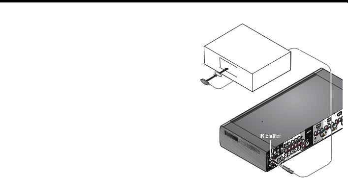
Using the IR emitter
Figure 14 IR emitters positioned on device front panel
IR emitters enable the system to control source devices even if they are in a cabinet, on multiple shelves, or hidden away. You should place an IR emitter on every device that you want to control using the Lifestyle® remote.
To use an IR emitter with one device
1.Plug the IR emitter cord connector into the Lifestyle® media center IR emitter connector.
2.Place the emitter so that the flat side is against the front panel of the source device.
3.Using the supplied adhesive pad, attach the emitter to the device.
20
English |
TAB 2 |
TAB 3 |
TAB |
TAB |
TAB 6 |
TAB |
TAB |
|
|
|
|
|
|
|
|
INSTALLATION
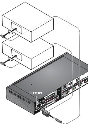
To use IR emitters with two or more devices |
Figure 15 IR emitters positioned on device front panel |
1.Plug the IR emitter extender connector into the Lifestyle® media center.
2.Plug the IR emitter cord connector (or additional
extenders) into the IR emitter extender.
3.Place each emitter so that the flat side is against the front panel of each device.
4. Using the supplied adhesive pads, attach the emitters to the devices.
Note: You can use up to four IR emitters with the system.
If you need additional IR emitter extenders, contact Bose® Customer Service. Refer to the address sheet included in the carton.
21
TAB |
TAB |
TAB 6Italiano |
TAB 5 |
TAB 4 |
TAB 3 |
TAB 2 |
English |
|
|
|
|
|
|
|
|
CONTROLS AND INDICATORS
The display
The display shows system messages. This includes program details, the current source that is playing, and any selected option.
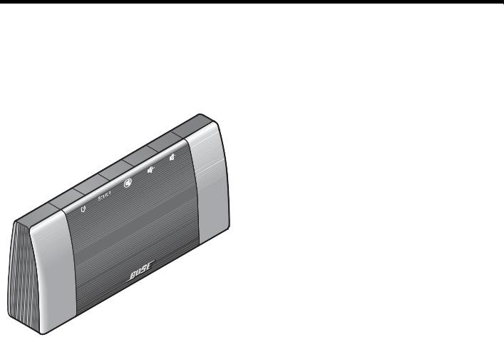
Figure 16 Lifestyle® system display
The buttons on the top of the display control the basic Lifestyle® system functions.
On/Off Turns the power on or off. When Bose® link is enabled, pressing and holding turns off all zones. (See “Setting up a second room with sound” on page 53.)
Source Steps through the available source selections.
Mute Silences the speakers in the main room.
When Bose® link is enabled, pressing and holding silences the speakers in all rooms. (See “Setting up a second room with sound” on page 53.)
Vol - Decreases the audio volume from the speakers.
Vol + Increases the audio volume from the speakers.
22
English |
TAB 2 |
TAB 3 |
TAB |
TAB |
TAB 6 |
TAB |
TAB |
|
|
|
|
|
|
|
|
CONTROLS AND INDICATORS
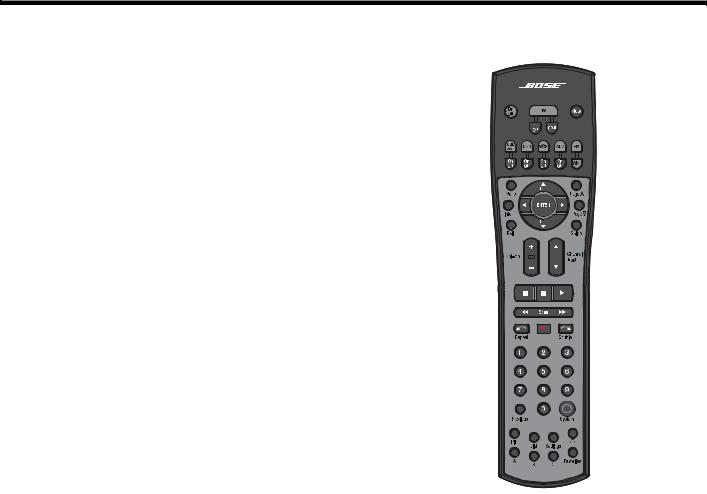
The remote control
Figure 17 Lifestyle® system remote control
The advanced radio frequency remote control works from almost anywhere in your home. There is no need to aim the remote at the display.
In addition to controlling your Lifestyle® system, the remote can be programmed to control each source device connected to your system.
The function of each remote control button is explained on the following pages. Then, remote control programming is covered according to the activity as follows:
•“Watching TV” on page 30
•“Controlling a cable or satellite box” on page 32
•“Controlling DVD playback” on page 34
•“Setting up to view videotapes” on page 36
•“Setting up an auxiliary (AUX) source” on page 38
•“Listening to the radio” on page 44
23
TAB |
TAB |
TAB 6Italiano |
TAB 5 |
TAB 4 |
TAB 3 |
TAB 2 |
English |
|
|
|
|
|
|
|
|
CONTROLS AND INDICATORS
Remote control button descriptions are arranged by general function on the following pages. Some buttons may not be physically grouped together. Refer to your remote control while reading the following button descriptions.
Before many of the buttons can function properly, your Lifestyle® system remote must be set up to control the associated source. See “Operation” beginning on page 30.
Note: A source is any device, such as a DVD player, that outputs video and/or audio and can connect to your Lifestyle® system.
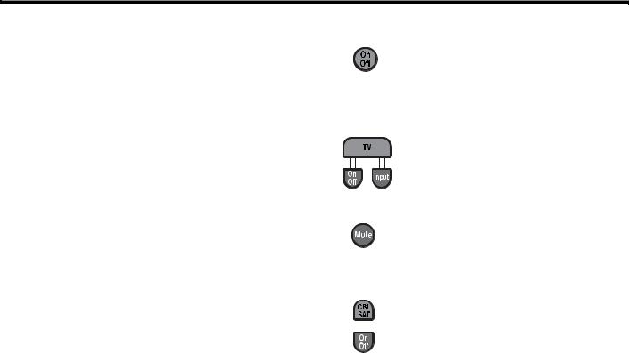
Power and source selection buttons
On/Off – Turns the Lifestyle® system on and off, selecting the last used source at turn-on. When Bose® link is enabled, pressing and holding turns off all zones. (See “Setting up a second room with sound” on page 53.)
• TV – Turns your Lifestyle® system on if it was off. Selects the TV as the source.
• On/Off – Turns the TV on and off.
• Input – Selects different video connectors on the TV.
Mute – Mutes or unmutes the volume. When Bose® link is enabled, pressing and holding silences the speakers in all rooms. (See “Setting up a second room with sound” on page 53.)
• CBL-SAT – Selects the source device plugged into the CBL-SAT connectors. Turns your Lifestyle® system on if it was off.
•On/Off – Turns your cable or satellite box on and off.
24
English |
TAB 2 |
TAB 3 |
TAB |
TAB |
TAB 6 |
TAB |
TAB |
|
|
|
|
|
|
|
|
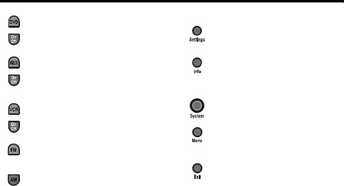
CONTROLS AND INDICATORS
•DVD – Selects the source device plugged into the DVD connectors. Turns your Lifestyle® system on if it was off.
•On/Off – Turns the DVD on and off.
•AUX – Selects the source device plugged into the AUX connectors. Turns your Lifestyle® system on if it was off.
•On/Off – Turns the AUX device on and off.
•VCR – Selects the source device plugged into the VCR connectors. Turns your Lifestyle® system on if it was off.
•On/Off – Turns the VCR on and off.
FM – Selects the built-in FM radio tuner, set to the station last selected. Turns your Lifestyle® system on if it was off.
AM – Selects the built-in AM radio tuner set to the station last selected. Turns your Lifestyle® system on if it was off.
Menu and navigation buttons
Settings – Enters or exits the Settings menu for the current source.
Info – Displays or exits the TV, cable, satellite box, or VCR/DVR information on the TV screen (when your TV, cable or satellite box, or VCR/DVR provides this feature).
System – Enters or exits the System main menu.
Menu – Displays the options menu for the current source (when your TV, cable or satellite box, or VCR/DVR provides this feature).
Exit
•Exits the Settings and System menus.
•Exits on-screen menus for TV, cable, satellite box, or VCR/DVR (when your TV, cable or satellite box, or VCR/DVR provides this feature).
25
TAB |
TAB |
TAB 6Italiano |
TAB 5 |
TAB 4 |
TAB 3 |
TAB 2 |
English |
|
|
|
|
|
|
|
|
CONTROLS AND INDICATORS
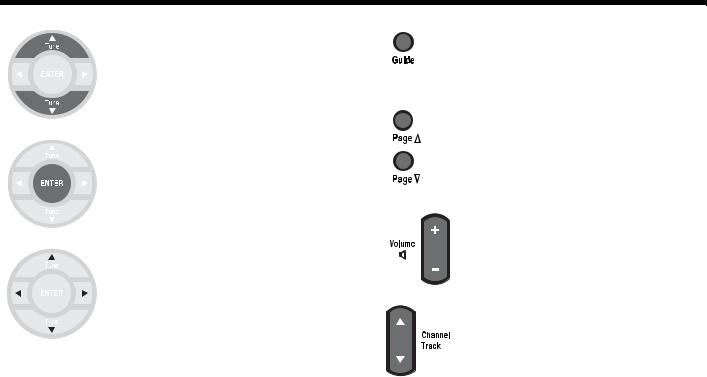
Tune Up/Down
•Tune the FM/AM radio up or down to the next frequency.
•Select the next or previous item in a menu list.
Enter – Confirm the selection of a menu item.
Arrow Keys – Move up, down, left, or right in a menu or screen.
Guide – Displays an electronic program guide (when your TV, cable, satellite box or VCR/DVR provides this feature).
Page Up/Down – Commands the TV, Cable, or Satellite box to move up or down a page in an on-screen guide.
Volume – Raises or lowers the volume.
• Pressing + raises the volume and unmutes the system (if muted).
• Pressing – lowers the volume.
Channel/Track – Skips backward or forward to the next TV, cable, or satellite channel, CD track, or DVD chapter.
26
 Loading...