

Page 1
Default Login Details
User’s Guide
LTE Series
LAN IP Address http://192.168.1.1
Login admin
Password See the Zyxel Device label
Version 1.00_2.00 Ed 3, 7/2019
Copyright © 2019 Zyxel Communications Corporation
Page 2

IMPORTANT!
READ CAREFULLY BEFORE USE.
KEEP THIS GUIDE FOR FUTURE REFERENCE.
This is a series User’s Guide. Screenshots and graphics in this book may differ slightly from what you see
due to differences in your product firmware or your computer operating system. Every effort has been
made to ensure that the information in this manual is accurate.
Related Documentation
•Quick Start Guide
The Quick Start Guide shows how to connect the Zyxel Device.
•More Information
Go to support.zyxel.com to find other information on the Zyxel Device
.
LTE Series User’s Guide
2
Page 3

Document Conventions
Warnings and Notes
These are how warnings and notes are shown in this guide.
Warnings tell you about things that could harm you or your Zyxel
Device.
Note: Notes tell you other important information (for example, other things you may need to
configure or helpful tips) or recommendations.
Syntax Conventions
• The LTE device in this user’s guide may be referred to as the “Zyxel Device” in this guide.
• Product labels, screen names, field labels and field choices are all in bold font.
• A right angle bracket ( > ) within a screen name denotes a mouse click. For example, Network Setting
> Routing > DNS Route means you first click Network Setting in the navigation panel, then the Routing
sub menu and finally the DNS Route tab to get to that screen.
Icons Used in Figures
Figures in this user guide may use the following generic icons. The Zyxel Device icon is not an exact
representation of your Zyxel Device.
Zyxel Device Generic Router Switch
Server Firewall USB Storage Device
Printer
LTE Series User’s Guide
3
Page 4

Contents Overview
Contents Overview
User’s Guide ......................................................................................................................................12
Introduction ........................................................................................................................................... 13
The Web Configurator ......................................................................................................................... 25
Quick Start ............................................................................................................................................. 34
Technical Reference ........................................................................................................................36
Connection Status ................................................................................................................................ 37
Broadband ............................................................................................................................................ 48
Wireless ................................................................................................................................................... 62
Home Networking ................................................................................................................................. 88
Routing ................................................................................................................................................. 110
Network Address Translation (NAT) ................................................................................................... 118
Dynamic DNS Setup ........................................................................................................................... 128
USB Service .......................................................................................................................................... 132
Firewall ................................................................................................................................................. 137
MAC Filter ............................................................................................................................................ 147
Certificates .......................................................................................................................................... 149
Log ....................................................................................................................................................... 158
Traffic Status ....................................................................................................................................... 161
ARP Table ............................................................................................................................................ 164
Routing Table ...................................................................................................................................... 166
Cellular WAN Status ........................................................................................................................... 169
System .................................................................................................................................................. 174
User Account ...................................................................................................................................... 175
Remote Management ....................................................................................................................... 178
TR-069 Client ........................................................................................................................................ 182
Time Settings ........................................................................................................................................ 185
Email Notification ................................................................................................................................ 188
Log Setting .......................................................................................................................................... 191
Firmware Upgrade .............................................................................................................................. 194
Backup/Restore .................................................................................................................................. 196
Diagnostic ........................................................................................................................................... 199
Troubleshooting .................................................................................................................................. 201
Appendices ............................................ ........................................................... ..............................208
LTE Series User’s Guide
4
Page 5

Table of Contents
Table of Contents
Document Conventions .................................................................. ....................................................3
Contents Overview .............................................................................................................................4
Table of Contents.................................................................................................................................5
Part I: User’s Guide.......................................................................................... 12
Chapter 1
Introduction ........................................................................................................................................13
1.1 Overview ......................................................................................................................................... 13
1.2 Application for the Zyxel Device .................................................................................................. 15
1.2.1 WAN Priority (LTE3301-PLUS) ................................................................................................. 17
1.3 Manage the Zyxel Device ............................................................................................................. 17
1.4 Good Habits for Managing the Zyxel Device ............................................................................. 17
1.5 Front and Bottom Panels ............................................................................................................... 17
1.5.1 LEDs (Lights) ........................................................................................................................... 19
1.5.2 Panel Ports & Buttons ............................................................................................................ 21
1.5.3 Turning On/Off WiFi ............................................................................................................... 21
1.5.4 The RESET Button .................................................................................................................... 23
Chapter 2
The Web Configurator........................................................................................................................25
2.1 Overview ......................................................................................................................................... 25
2.1.1 Access the Web Configurator ............................................................................................. 25
2.2 Web Configurator Layout .............................................................................................................. 27
2.2.1 Settings Icon .......................................................................................................................... 27
2.2.2 Widget Icon ........................................................................................................................... 32
Chapter 3
Quick Start..........................................................................................................................................34
3.1 Overview ......................................................................................................................................... 34
3.2 Quick Start Setup ............................................................................................................................ 34
3.3 Time Zone ........................................................................................................................................ 34
3.4 WiFi Setup ........................................................................................................................................ 35
3.5 Quick Start Setup-Finish .................................................................................................................. 35
LTE Series User’s Guide
5
Page 6

Table of Contents
Part II: Technical Reference........................................................................... 36
Chapter 4
Connection Status..............................................................................................................................37
4.1 Connection Status Overview ........................................................................................................ 37
4.1.1 Connectivity .......................................................................................................................... 37
4.1.2 System Info ............................................................................................................................. 38
4.1.3 Cellular Info ............................................................................................................................ 40
4.1.4 WiFi Settings ........................................................................................................................... 44
4.1.5 LAN ......................................................................................................................................... 46
Chapter 5
Broadband..........................................................................................................................................48
5.1 Overview ......................................................................................................................................... 48
5.1.1 What You Can Do in this Chapter ....................................................................................... 48
5.1.2 What You Need to Know ..................................................................................................... 49
5.1.3 Before You Begin ................................................................................................................... 49
5.2 Broadband ...................................................................................................................................... 49
5.2.1 Add/Edit Internet Connection .............................................................................................50
5.3 Ethernet WAN .................................................................................................................................. 54
5.4 Cellular WAN ................................................................................................................................... 54
5.5 Cellular SIM Configuration ............................................................................................................. 56
5.6 Cellular Band Configuration .......................................................................................................... 57
5.7 PLMN Configuration ....................................................................................................................... 58
5.8 IP Passthrough ................................................................................................................................. 60
Chapter 6
Wireless...............................................................................................................................................62
6.1 Overview ......................................................................................................................................... 62
6.1.1 What You Can Do in this Chapter ....................................................................................... 62
6.1.2 What You Need to Know ..................................................................................................... 62
6.2 General Settings ............................................................................................................................. 63
6.2.1 No Security ............................................................................................................................. 64
6.2.2 More Secure (WPA2-PSK) ..................................................................................................... 65
6.3 MAC Authentication ...................................................................................................................... 66
6.4 WPS ................................................................................................................................................... 68
6.5 WMM ................................................................................................................................................ 70
6.6 Others Settings ................................................................................................................................ 71
6.7 WLAN Scheduler ............................................................................................................................. 73
6.7.1 Add/Edit Rules ..................................................................74
6.8 Technical Reference ...................................................................................................................... 75
6.8.1 WiFi Network Overview ......................................................................................................... 75
6.8.2 Additional Wireless Terms ..................................................................................................... 77
LTE Series User’s Guide
6
Page 7

Table of Contents
6.8.3 WiFi Security Overview .......................................................................................................... 77
6.8.4 Signal Problems ..................................................................................................................... 79
6.8.5 BSS ........................................................................................................................................... 79
6.8.6 Preamble Type ...................................................................................................................... 80
6.8.7 WiFi Protected Setup (WPS) ................................................................................................. 80
Chapter 7
Home Networking..............................................................................................................................88
7.1 Overview ......................................................................................................................................... 88
7.1.1 What You Can Do in this Chapter ....................................................................................... 88
7.1.2 What You Need To Know ..................................................................................................... 88
7.2 LAN Setup ........................................................................................................................................ 89
7.3 Static DHCP ..................................................................................................................................... 93
7.3.1 Before You Begin ................................................................................................................... 93
7.4 UPnP ................................................................................................................................................. 95
7.5 Technical Reference ...................................................................................................................... 96
7.6 Turn on UPnP in Windows 7 Example ............................................................................................ 97
7.6.1 Auto-discover Your UPnP-enabled Network Device ........................................................ 98
7.7 Turn on UPnP in Windows 10 Example ........................................................................................ 100
7.7.1 Auto-discover Your UPnP-enabled Network Device ...................................................... 102
7.8 Web Configurator Easy Access in Windows 7 ........................................................................... 105
7.9 Web Configurator Easy Access in Windows 10 ......................................................................... 107
Chapter 8
Routing..............................................................................................................................................110
8.1 Overview ....................................................................................................................................... 110
8.2 Configure Static Route ................................................................................................................ 110
8.2.1 Add/Edit Static Route ......................................................................................................... 111
8.3 DNS Route ...................................................................................................................................... 113
8.3.1 Add/Edit DNS Route ........................................................................................................... 113
8.4 Policy Route .................................................................................................................................. 114
8.4.1 Add/Edit Policy Route ........................................................................................................ 116
8.5 RIP Overview ................................................................................................................................. 117
8.5.1 RIP ......................................................................................................................................... 117
Chapter 9
Network Address Translation (NAT)................................................................................................ 118
9.1 Overview ....................................................................................................................................... 118
9.1.1 What You Can Do in this Chapter ..................................................................................... 118
9.1.2 What You Need To Know ................................................................................................... 118
9.2 Port Forwarding Overview ........................................................................................................... 119
9.2.1 Port Forwarding ................................................................................................................... 120
9.2.2 Add/Edit Port Forwarding ................................................................................................... 121
LTE Series User’s Guide
7
Page 8

Table of Contents
9.3 Port Triggering ............................................................................................................................... 122
9.3.1 Add/Edit Port Triggering Rule ............................................................................................. 124
9.4 DMZ ................................................................................................................................................ 125
9.5 ALG ................................................................................................................................................. 126
Chapter 10
Dynamic DNS Setup.........................................................................................................................128
10.1 DNS Overview ............................................................................................................................. 128
10.1.1 What You Can Do in this Chapter ................................................................................... 128
10.1.2 What You Need To Know ................................................................................................. 128
10.2 DNS Entry ..................................................................................................................................... 129
10.2.1 Add/Edit DNS Entry ........................................................................................................... 129
10.3 Dynamic DNS .............................................................................................................................. 130
Chapter 11
USB Service........................................... ... .... .... ............................................ ... ..................................132
11.1 USB Service Overview ............................................................................................................... 132
11.1.1 What You Need To Know ................................................................................................. 132
11.1.2 Before You Begin ............................................................................................................... 133
11.2 USB Service .................................................................................................................................. 133
11.2.1 The Add New Share Screen ............................................................................................. 135
11.2.2 The Add New User Screen ............................................................................................... 136
Chapter 12
Firewall..............................................................................................................................................137
12.1 Overview ..................................................................................................................................... 137
12.1.1 What You Need to Know About Firewall ........................................................................ 137
12.2 Firewall ......................................................................................................................................... 138
12.2.1 What You Can Do in this Chapter ................................................................................... 138
12.3 Firewall General Settings ............................................................................................................ 138
12.4 Protocol (Customized Services) ................................................................................................ 140
12.4.1 Add Customized Service ..................................................................................................140
12.5 Access Control (Rules) ............................................................................................................... 141
12.5.1 Access Control Add New ACL Rule ................................................................................ 142
12.6 DoS ............................................................................................................................................... 144
12.7 Firewall Technical Reference .................................................................................................... 144
12.7.1 Firewall Rules Overview .................................................................................................... 145
12.7.2 Guidelines For Security Enhancement With Your Firewall ............................................ 146
12.7.3 Security Considerations .................................................................................................... 146
Chapter 13
MAC Filter .........................................................................................................................................147
13.1 MAC Filter Overview ................................................................................................................... 147
LTE Series User’s Guide
8
Page 9

Table of Contents
13.2 MAC Filter .................................................................................................................................... 147
Chapter 14
Certificates .......................................................................................................................................149
14.1 Overview ..................................................................................................................................... 149
14.1.1 What You Can Do in this Chapter ................................................................................... 149
14.2 Local Certificates ....................................................................................................................... 149
14.2.1 Create Certificate Request ............................................................................................. 150
14.2.2 View Certificate Request ................................................................................................. 151
14.3 Trusted CA ................................................................................................................................... 153
14.4 Import Trusted CA Certificate ................................................................................................... 154
14.5 View Trusted CA Certificate ...................................................................................................... 154
14.6 Certificates Technical Reference ............................................................................................. 155
14.6.1 Verify a Certificate ............................................................................................................ 156
Chapter 15
Log ..................................... ................................................ ...............................................................158
15.1 Log Overview .............................................................................................................................. 158
15.1.1 What You Can Do in this Chapter ................................................................................... 158
15.1.2 What You Need To Know ................................................................................................. 158
15.2 System Log .................................................................................................................................. 159
15.3 Security Log ................................................................................................................................. 159
Chapter 16
Traffic Status .....................................................................................................................................161
16.1 Traffic Status Overview ............................................................................................................... 161
16.1.1 What You Can Do in this Chapter ................................................................................... 161
16.2 WAN Status .................................................................................................................................. 161
16.3 LAN Status .................................................................................................................................... 162
Chapter 17
ARP Table..........................................................................................................................................164
17.1 ARP Table Overview ................................................................................................................... 164
17.1.1 How ARP Works .................................................................................................................. 164
17.2 ARP Table .................................................................................................................................... 165
Chapter 18
Routing Table....................................................................................................................................166
18.1 Routing Table Overview ............................................................................................................ 166
18.2 Routing Table .............................................................................................................................. 166
Chapter 19
Cellular WAN Status ........................................................................................................................169
LTE Series User’s Guide
9
Page 10

Table of Contents
19.1 Cellular WAN Status Overview .................................................................................................. 169
19.2 Cellular WAN Status .................................................................................................................... 169
Chapter 20
System...............................................................................................................................................174
20.1 System Overview ........................................................................................................................ 174
20.2 System .......................................................................................................................................... 174
Chapter 21
User Account.............................................................. ... .... ............................................ ...................175
21.1 User Account Overview ............................................................................................................. 175
21.2 User Account .............................................................................................................................. 175
21.2.1 User Account Add/Edit .................................................................................................... 176
Chapter 22
Remote Management.....................................................................................................................178
22.1 Overview ..................................................................................................................................... 178
22.2 MGMT Services ............................................................................................................................ 178
22.3 MGMT Services for IP Passthrough ............................................................................................ 179
22.4 Trust Domain ................................................................................................................................ 180
22.5 Add Trust Domain ....................................................................................................................... 180
Chapter 23
TR-069 Client....... ............................................. ... ............................................ .... ..............................182
23.1 Overview ..................................................................................................................................... 182
23.2 TR-069 Client ................................................................................................................................ 182
Chapter 24
Time Settings.....................................................................................................................................185
24.1 Time Settings Overview .............................................................................................................. 185
24.2 Time .............................................................................................................................................. 185
Chapter 25
Email Notification.............................................................................................................................188
25.1 Email Notification Overview ...................................................................................................... 188
25.2 Email Notification ........................................................................................................................ 188
25.2.1 Email Notification Edit ....................................................................................................... 189
Chapter 26
Log Setting ................................ ... .... .... ............................................ ... .............................................191
26.1 Log Setting Overview ................................................................................................................. 191
26.2 Log Setting ................................................................................................................................... 191
LTE Series User’s Guide
10
Page 11

Table of Contents
Chapter 27
Firmware Upgrade........................................................................... ... .... .........................................194
27.1 Overview ..................................................................................................................................... 194
27.2 Firmware Upgrade ...................................................................................................................... 194
Chapter 28
Backup/Restore ...............................................................................................................................196
28.1 Backup/Restore Overview ........................................................................................................ 196
28.2 Backup/Restore .......................................................................................................................... 196
28.3 Reboot ......................................................................................................................................... 197
Chapter 29
Diagnostic.........................................................................................................................................199
29.1 Diagnostic Overview .................................................................................................................. 199
29.2 Ping/TraceRoute/Nslookup Test ................................................................................................ 199
Chapter 30
Troubleshooting................................................................................................................................201
30.1 Overview ..................................................................................................................................... 201
30.2 Power and Hardware Connections ......................................................................................... 201
30.3 Zyxel Device Access and Login ................................................................................................ 202
30.4 Internet Access ........................................................................................................................... 203
30.5 USB Device Connection ............................................................................................................ 205
30.6 UPnP ............................................................................................................................................. 205
30.7 SIM Card ...................................................................................................................................... 206
30.8 Cellular Signal ............................................................................................................................. 206
Part III: Appendices......................................................................................208
Appendix A Customer Support ..................................................................................................... 209
Appendix B IPv6............................................................................................................................... 215
Appendix C Legal Information ...................................................................................................... 222
Index.................................................................................................................................................230
LTE Series User’s Guide
11
Page 12

PART I
User’s Guide
12
Page 13

1.1 Overview
Zyxel Device refers to these models as outlined below.
The following table describes the feature differences of the Zyxel Device by model.
Table 1 Zyxel Device Comparison Table
2.4G WLAN V V V
5G WLAN V - -
LTE Speed 300/50 Mbps 150/50 Mbps
CHAPTER 1
Introduction
• LTE3301-PLUS • LTE7480-M804
• LTE7240-M403 • LTE7480-S905
• LTE7461-M602 • LTE7490-M604
LTE3301-PLUS LTE7240-M403 LTE7461-M602
(FDD-LTE)
400/150 Mbps
(FDD-LTE)
Note: These are the theoretical downlink/uplink rates. LTE
speed is affected by strength of signal, network
congestion, LTE band(s) or frequency(-ies) to which
your Zyxel Device is connected, and so forth.
Gigabit Ethernet
Port
Ethernet WAN Convert the forth LAN
IP Passthrough Available when the
USB for File
Sharing
External
Antennas
PoE Injector - V V
Wall Mount - V V
Pole Mount - - V
Firmware
Version
port to work as a WAN
forth LAN port doesn’t
act as an Ethernet
VVV
--
port.
VV
WAN port.
VVV
V- -
1.00 2.00 2.00
LTE Series User’s Guide
13
Page 14

Chapter 1 Introduction
Table 2 Zyxel Device Comparison Table
LTE7480-M804 LTE7480-S905 LTE7490-M904
2.4G WLAN V V V
5G WLAN---
LTE Speed 600/100 Mbps 573/15.1 Mbps
(TDD-LTE config. #2)
1200/150 Mbps
Note: These are the theoretical downlink/uplink rates. LTE
speed is affected by strength of signal, network
congestion, LTE band(s) or frequency(-ies) to which
your Zyxel Device is connected, and so forth.
Gigabit Ethernet
Port
Ethernet WAN---
IP Passthrough V V V
USB for File
Sharing
External
Antennas
PoE Injector - V -
Wall Mount V V V
Pole Mount V V V
Firmware
Version
VVV
-V-
---
1.00 2.00 1.00
The Zyxel Device is an LTE (Long Term Evolution) router that supports (but not limited to) the following:
• Cellular WAN Backup (LTE3301-PLUS)
• Gigabit Ethernet connection
• DHCP (Dynamic Host Configuration Protocol) server
• NAT (Network Address Translation)
• DMZ (Demilitarized Zone)
• Port Forwarding/Triggering
• ALG (Application Layer Gateway)
• Embedded Bridge/Router mode
• Dynamic DNS (Domain Name System) for the first APN (Access Point Name)
• Static/Dynamic Route setting for RIP (Routing Information Protocol)
• Remote Management under Bridge mode
• Address Resolution Protocol (ARP)
• Firewall that uses Stateful Packet Inspection (SPI) technology
• Protects against Denial of Service (DoS) attacks
• Filter of LAN MAC address, LAN IP address and URLs
• Local and remote device management
• Firmware upgrade via TR-069 and Web Configurator
LTE Series User’s Guide
14
Page 15
Chapter 1 Introduction
LTE
The embedded Web-based Configurator enables straightforward management and maintenance. Just
insert the SIM card (with an active data plan) and make the hardware connections. See the Quick Start
Guide for how to do the hardware installation, wall/pole mounting, and Internet setup.
1.2 Application for the Zyxel Device
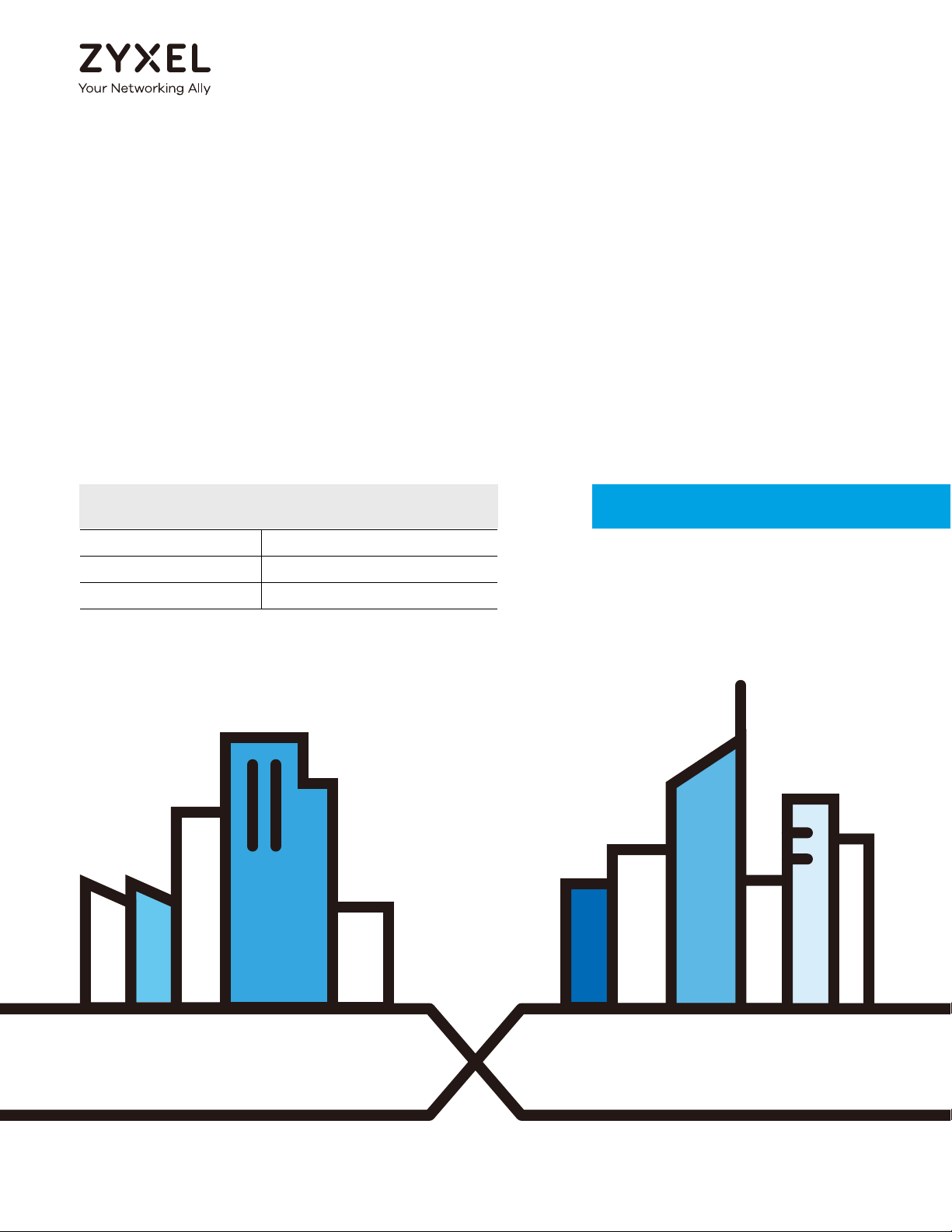
Wireless WAN
TheZyxel Device can connect to the Internet through a 2G/3G/4G LTE SIM card to access a wireless
WAN connection. Just insert a SIM card into the SIM card slot at the bottom of the Zyxel Device.
Note: You must insert the SIM card into the card slot before turning on the Zyxel Device.
You can install two external antennas to improve your wireless WAN signal strength. See Table 1 on page
13 for the feature differences.
Wireless LAN (WiFi)
Wireless clients can connect to the LTE Device to access network resources and the Internet. Your LTE
Device supports WiFi Protected Setup (WPS), which allows you to quickly set up a wireless network with
strong security.
Internet Access
Your Zyxel Device provides shared Internet access by connecting to an LTE network. A computer can
connect to the Zyxel Device’s PoE injector or a LAN port for configuration via the Web Configurator. See
Table 1 on page 13 for the feature differences.
LTE Series User’s Guide
15
Page 16
Chapter 1 Introduction
LTE (4G)/3G/2G
WiFi
Figure 1 Zyxel Device’s Internet Access Application
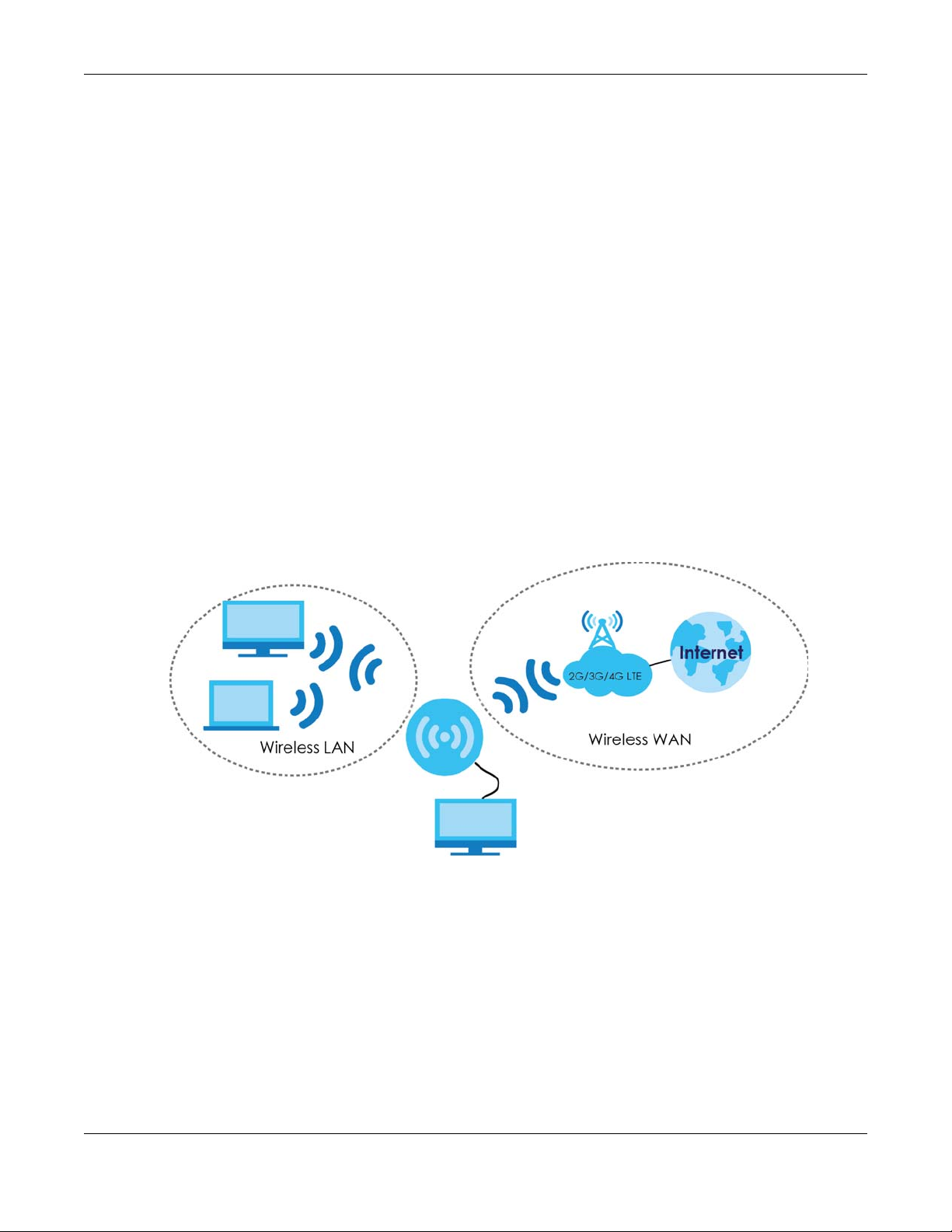
Carrier Aggregation (LTE7480-M804 & LTE7490-M904)
Carrier Aggregation (CA) is a technology to deliver high downlink data rates by combining more than
one carrier in the same or different bands together.
Figure 2 Zyxel Device’s CA Application
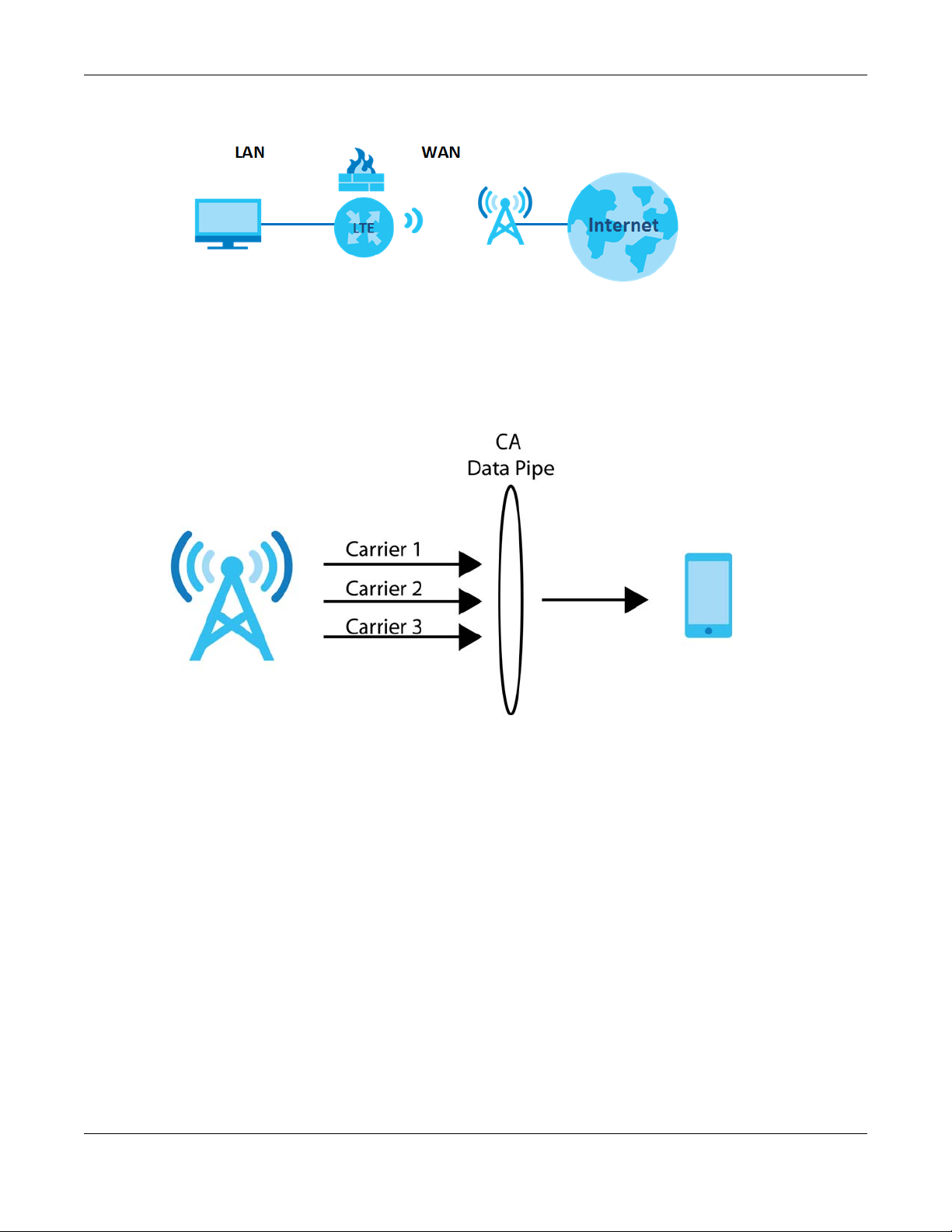
Ethernet WAN (LTE3301-PLUS)
If you have another broadband modem or router available, you can use the Ethernet WAN port and
then connect it to the broadband modem or router. This way, you can access the Internet via an
Ethernet connection and still use the Firewall function on the Zyxel Device.
Note: Convert LAN port number four as a WAN port first. See Section 5.3 on page 54 for more
information about the Network Setting > Broadband > Ethernet WAN screen.
LTE Series User’s Guide
16
Page 17
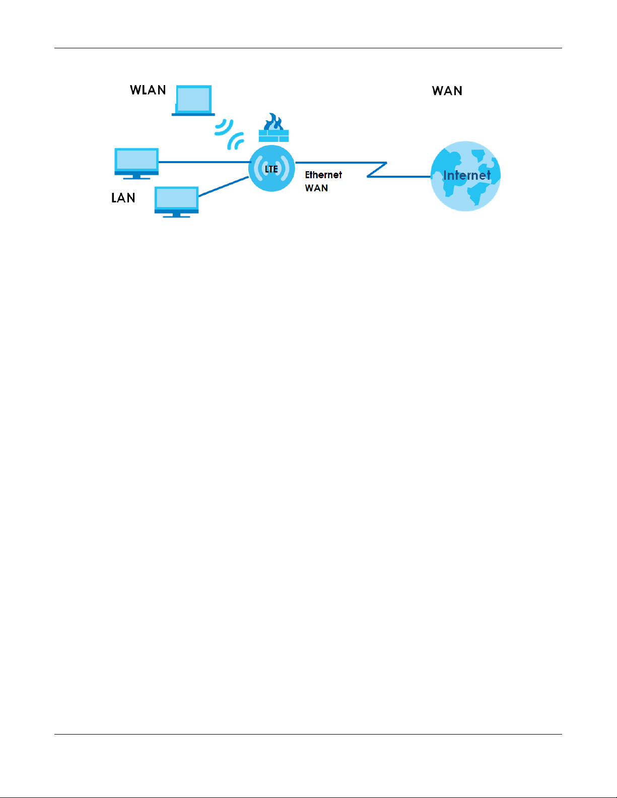
Figure 3 Zyxel Device’s Internet Access Application: Ethernet WAN
1.2.1 WAN Priority (LTE3301-PLUS)
The WAN connection priority is as follows:
1 Ethernet WAN
2 Cellular WAN (3G/4G)
Chapter 1 Introduction
1.3 Manage the Zyxel Device
Use the Web Configurator for management of the Zyxel Device using a (supported) web browser.
1.4 Good Habits for Managing the Zyxel Device
Do the following things regularly to make the Zyxel Device more secure and to manage the Zyxel
Device more effectively.
• Change the password. Use a password that’s not easy to guess and that consists of different types of
characters, such as numbers and letters.
• Write down the password and put it in a safe place.
• Back up the configuration (and make sure you know how to restore it). Refer to Section 28.2 on page
196. Restoring an earlier working configuration may be useful if the Zyxel Device becomes unstable or
even crashes. If you forget your password to access the Web Configurator, you will have to reset the
Zyxel Device to its factory default settings. If you backed up an earlier configuration file, you would
not have to totally re-configure the Zyxel Device. You could simply restore your last configuration.
Write down any information your ISP provides you.
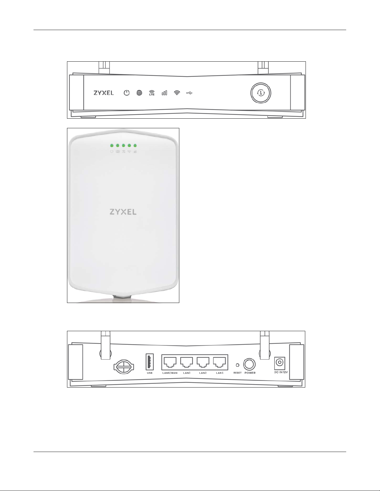
1.5 Front and Bottom Panels
The LED indicators are located on the front (LTE7240-M403 & LTE3301-PLUS) / bottom panel (LTE7461M602 / LTE7480-M804 / LTE7480-S905 / LTE7490-M904).
LTE Series User’s Guide
17
Page 18
Chapter 1 Introduction
Front Panels
Figure 4 Front Panel (LTE3301-PLUS)
Figure 5 Front Panel (LTE7240-M403)
Bottom & Rear Panels
Figure 6 Rear Panel (LTE3301-PLUS)
LTE Series User’s Guide
18
Page 19
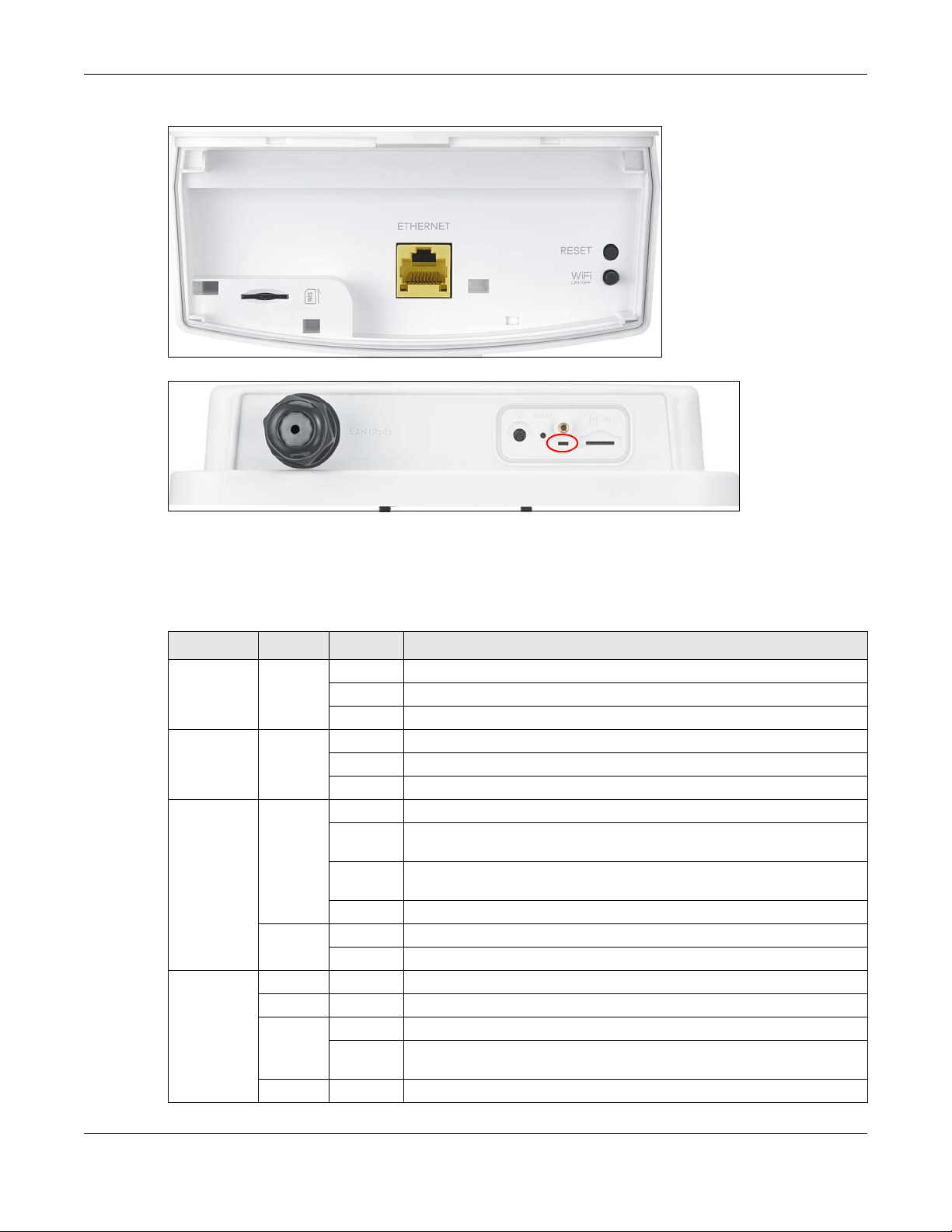
Chapter 1 Introduction
LED
Figure 7 Bottom Panel (LTE7240-M403)
Figure 8 Bottom Panel (LTE7461-M602 / LTE7480-M804 / LTE7480-S905 / LTE7490-M904)
1.5.1 LEDs (Lights)
None of the LEDs are on if the Zyxel Device is not receiving power.
Table 3 LTE3301-PLUS LED Descriptions
LED COLOR STATUS DESCRIPTION
POWER White On The Zyxel Device is receiving power and ready for use.
Internet White On There is Internet connection.
LTE/3G White On The Zyxel Device is registered and successfully connected to a 4G network.
Signal
Strength
Blinking The Zyxel Device is booting or self-testing.
Off The Zyxel Device is not receiving power.
Blinking The Zyxel Device is sending or receiving IP traffic.
Off There is no Internet connection.
Blinking
(slow)
Blinking
(fast)
Off There is no service.
Green On The Zyxel Device has an Ethernet connection on the WAN.
Off There is no Ethernet connection on the WAN.
Green On The signal strength is excellent.
Amber On The signal strength is fair.
Red On The signal strength is poor.
Blinking There is no SIM card inserted, no signal, or the signal strength is below the
Off The SIM card is invalid, or the PIN code is not correct.
The Zyxel Device is connected to a 3G network.
The Zyxel Device is trying to connect to a 3G/4G network.
poor level.
LTE Series User’s Guide
19
Page 20

Chapter 1 Introduction
Table 3 LTE3301-PLUS LED Descriptions (continued)
LED COLOR STATUS DESCRIPTION
WLAN Green On The 2.4 GHz wireless network is activated.
Blinking
(slow)
Blinking
(fast)
White On The 5 GHz wireless network is activated.
Blinking
(slow)
Blinking
(fast)
Off The wireless network is not activated.
USB White On The Zyxel Device recognizes a USB connection through the USB port.
Blinking The Zyxel Device is sending/receiving data to/from the USB device
Off The Zyxel Device does not detect a USB connection through the USB port.
The Zyxel Device is setting up a WPS connection with a 2.4 GHz wireless
client.
The Zyxel Device is communicating with 2.4 GHz wireless clients.
The Zyxel Device is setting up a WPS connection with a 5 GHz wireless client.
The Zyxel Device is communicating with 2.4 GHz and 5 GHz wireless clients.
connected to it.
Note: Blinking (slow) means the LED blinks once per second. Blinking (fast) means the LED
blinks once per 0.5 second.
Table 4 LTE7240-M403 LED Descriptions
LED COLOR STATUS DESCRIPTION
POWER Green On The Zyxel Device is receiving power and ready for use.
Blinking The Zyxel Device is booting or self-testing.
Off The Zyxel Device is not receiving power.
ETHERNET Green On The Zyxel Device has a successful 10/100/1000 Mbps Ethernet connection
with a device on the Local Area Network (LAN).
Off The Zyxel Device does not have an Ethernet connection with the LAN.
LTE/3G/2G Green On The Zyxel Device is registered and successfully connected to a 4G network.
Blinking
(slow)
Blinking
(fast)
Off There is no service.
WLAN Green On The wireless network is activated.
Off The wireless network is not activated.
Signal
Strength
Green On The signal strength is excellent.
Orange On The signal strength is fair.
Red On The signal strength is poor.
Blinking There is no SIM card inserted, the SIM card is invalid, the PIN code is not
Off There is no signal or the signal strength is below the poor level.
The Zyxel Device is connected to a 3G/2G network.
The Zyxel Device is trying to connect to a 4G/3G/2G network.
correct.
Note: Blinking (slow) means the LED blinks once per second. Blinking (fast) means the LED
blinks once per 0.2 second.
LTE Series User’s Guide
20
Page 21
Table 5 LTE7461-M602 / LTE7480-M804 / LTE7480-S905 / LTE7490-M904 LED Descriptions
COLOR STATUS DESCRIPTION
Red Blinking The Zyxel Device is booting or self-testing.
On The Zyxel Device encountered an error.
Green Blinking The Zyxel Device is trying to connect to the Internet.
On The Zyxel Device is connected to the Internet.
Amber Blinking The Zyxel Device WiFi is on.
1.5.2 Panel Ports & Buttons
The connection ports are located on the bottom/rear panels.
The following table describes the items on the bottom panel.
Table 6 Panel Ports and Buttons
LABEL DESCRIPTION
ANT1-ANT2 Install the external antennas to strengthen the cellular signal.
USB The USB port of the Zyxel Device is used for file sharing.
LAN/
Ethernet
WiFi Press the WLAN button for more than five seconds to enable the wireless function.
WPS After the wireless function is enabled, press the WLAN button for more than one second but less
Reset Press the button for more than five seconds to return the Zyxel Device to the factory defaults.
POWER
Button
Power Connect the power adapter and press the POWER button to start the LTE3301-PLUS.
Reboot Press the RESET button for more than 2 seconds but less than 5 seconds, it will cause the system to
SIM card Insert a micro-SIM card into the slot with the chip facing down and the beveled corner in the top
Connect a computer via the PoE injector for configuration.
Connect the PoE injector to a power outlet to start the device.
than five seconds to quickly set up a secure wireless connection between the device and a WPScompatible client.
Press the POWER button after the power adapter is connected to start the LTE3301-PLUS.
reboot.
left corner.
Chapter 1 Introduction
1.5.3 Turning On/Off WiFi
Use the WPS or WiFi/WPS button on the Zyxel Device to turn on or turn off the wireless network.
Note: Use the WiFi function of the LTE7461-M602 / LTE7480-M804 / LTE7480-S905 / LTE7490-M904
for configuration (for example, connect to the LTE Ally app of your mobile device to
find the optimal LTE signal strength and manage your LTE7461-M602 / LTE7480-M804 /
LTE7480-S905 / LTE7490-M904).
LTE Series User’s Guide
21
Page 22
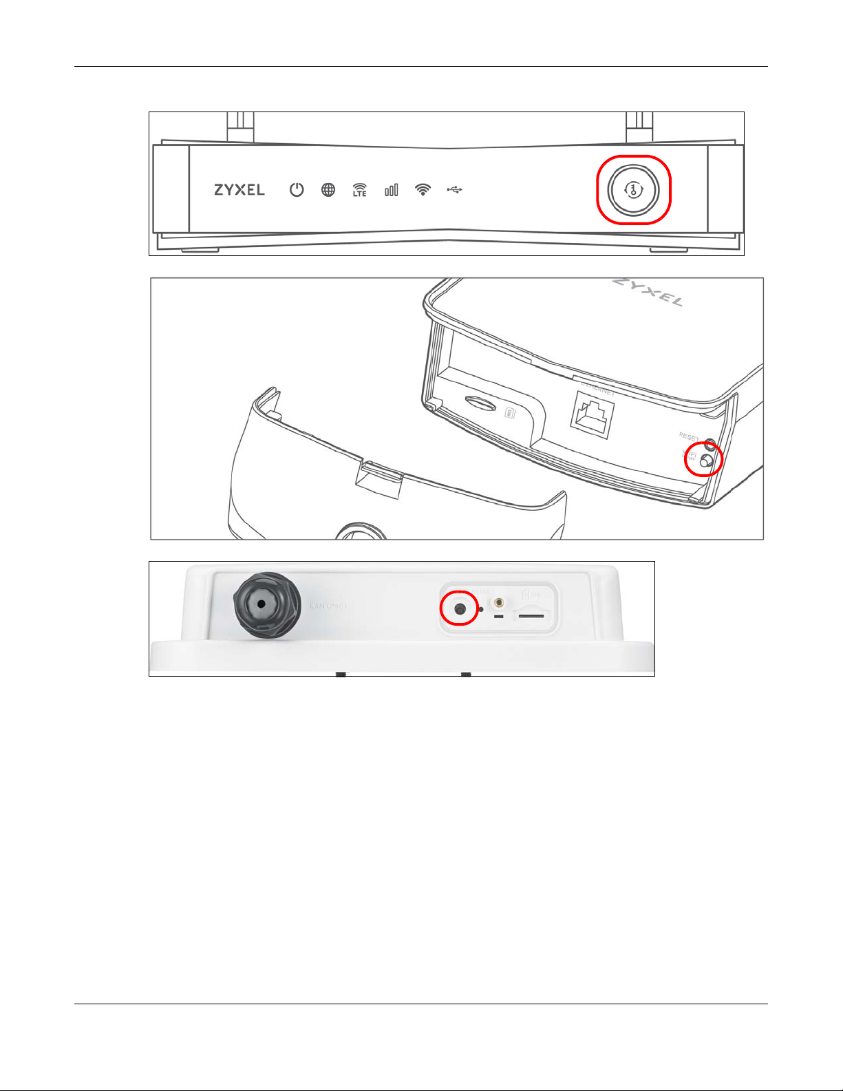
Chapter 1 Introduction
Figure 9 LTE3301-PLUS WiFI/WPS Button
Figure 10 LTE7240-M403 WiFi Button
Figure 11 LTE7461-M602 / LTE7480-M804 / LTE7480-S905 / LTE7490-M904 WiFi Button
To turn on WiFi:
1 Make sure the POWER LED is on and not blinking.
2 Press the WiFi or WiFi/WPS button for more than 5 seconds and release it.
For LTE3301-PLUS:
Once WiFi is turned on, the WLAN LED turns green/white.
For LTE7240-M403:
Once WiFi is turned on, the WLAN LED shines green.
For LTE7461-M602 / LTE7480-M804 / LTE7480-S905 / LTE7490-M904:
Once WiFi is turned on, the LED blinks amber.
LTE Series User’s Guide
22
Page 23
Chapter 1 Introduction
To activate WPS (WiFi must be already on):
You can also quickly set up a secure wireless connection between the Zyxel Device and a WPScompatible client by adding one device at a time.
1 Press the WiFi or WiFi/WPS button for more than 1 second but less than 5 seconds and release it (pressing
more than 5 seconds will turn off WiFi).
2 Press the WPS button on another WPS-enabled device within range of the Zyxel Device.
For LTE3301-PLUS:
Once a wireless connection is ready, the WLAN LED turns green/white.
For LTE7240-M403:
Once a wireless connection is ready, the WLAN LED shines green.
For LTE7461-M602 / LTE7480-M804 / LTE7480-S905 / LTE7490-M904:
Once a wireless connection is ready, the LED blinks amber.
To turn off the wireless network:
Press the WiFi or WiFi/WPS button for more than 5 seconds.
For LTE3301-PLUS:
The WLAN LED turns off when the wireless network is off.
For LTE7240-M403:
The WLAN LED turns off when the wireless network is off.
For LTE7461-M602 / LTE7480-M804 / LTE7480-S905 / LTE7490-M904:
The amber LED turns off.
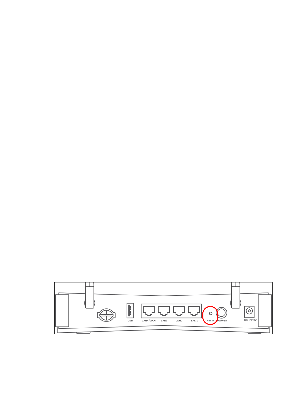
1.5.4 The RESET Button
If you forget your password or cannot access the Web Configurator, you will need to use the RESET
button of the Zyxel Device as shown in the following figure to reload the factory-default configuration
file. This means that you will lose all configurations that you had previously saved. The password will be
reset to the default (see the Zyxel Device label) and the IP address will be reset to 192.168.1.1.
Figure 12 Reset Button (LTE3301-PLUS)
LTE Series User’s Guide
23
Page 24
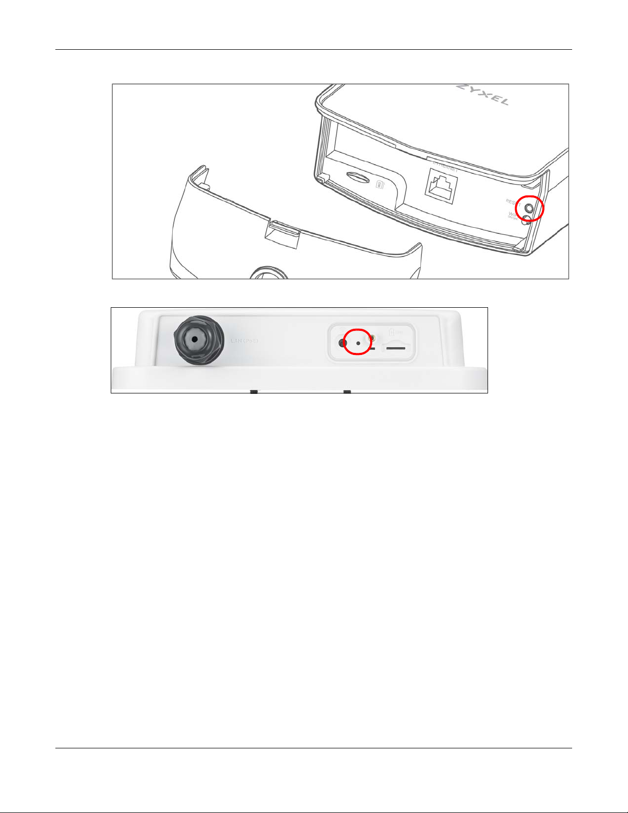
Chapter 1 Introduction
Figure 13 Reset Button (LTE7240-M403)
Figure 14 Reset Button (LTE7461-M602 / LTE7480-M804 / LTE7480-S905 / LTE7490-M904)
1 Make sure the Zyxel Device is connected to power and POWER LED is on.
2 To set the Zyxel Device back to the factory default settings, press the RESET button for 5 seconds.
Note: If you press the RESET button for more than 2 seconds but less than 5 seconds, it will
cause the system to reboot.
LTE Series User’s Guide
24
Page 25
2.1 Overview
The Web Configurator is an HTML-based management interface that allows easy Zyxel Device setup
and management via Internet browser. Use Internet Explorer 8.0 and later versions or Mozilla Firefox 3
and later versions or Safari 2.0 and later versions. The recommended screen resolution is 1024 by 768
pixels.
In order to use the Web Configurator you need to allow:
• Web browser pop-up windows from your Zyxel Device. Web pop-up blocking is enabled by default in
Windows 10.
• JavaScript (enabled by default).
• Java permissions (enabled by default).
CHAPTER 2
The Web Configurator
Note: The LTE7240-M403 was used for the Web Configurator illustrations in this User’s Guide.
2.1.1 Access the Web Configurator
1 Make sure your Zyxel Device hardware is properly connected (refer to the Quick Start Guide).
2 Launch your web browser. If the Zyxel Device does not automatically re-direct you to the login screen,
go to http://192.168.1.1.
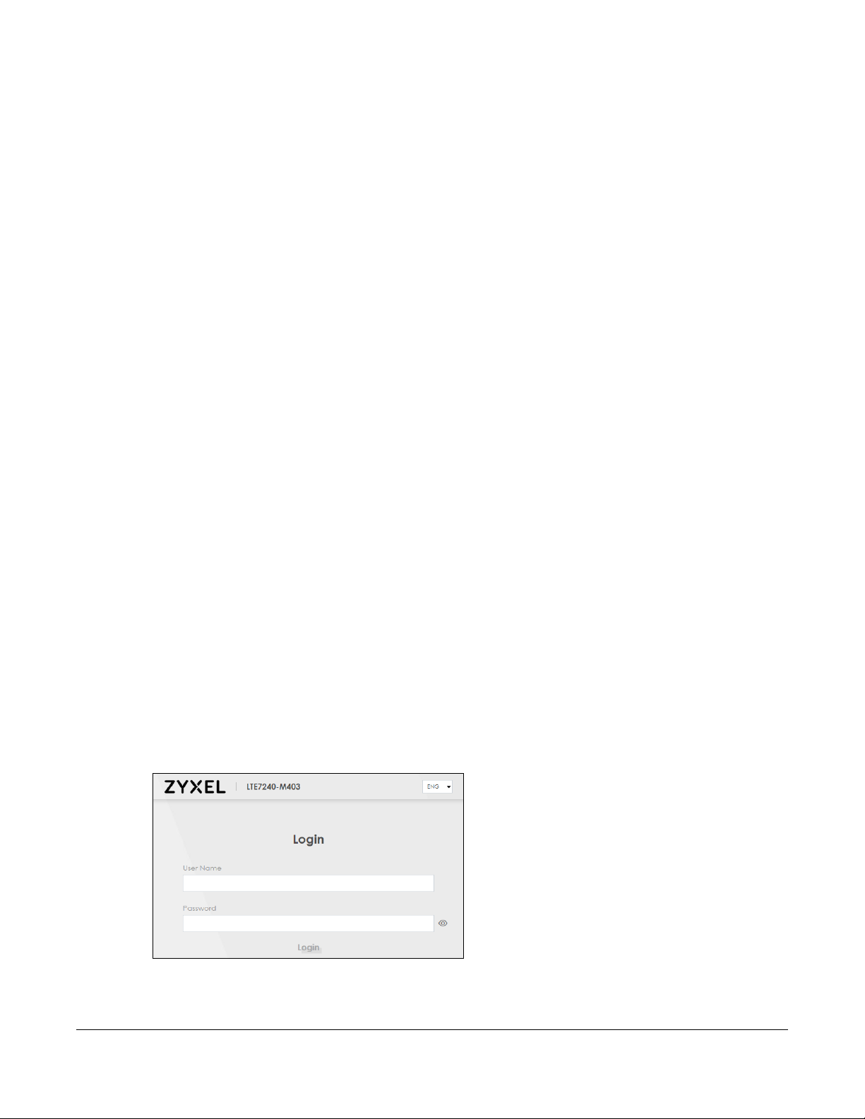
3 A password screen displays. Select the language you prefer (upper right).
4 To access the Web Configurator and manage the Zyxel Device, type the default username admin and
the randomly assigned default password (see the Zyxel Device label) in the Login screen and click Login.
If you have changed the password, enter your password and click Login.
Figure 15 Password Screen
LTE Series User’s Guide
25
Page 26
Chapter 2 The Web Configurator
Note: The first time you enter the password, you will be asked to change it. Make sure the new
password must contain at least one uppercase letter, one lowercase letter and one
number.
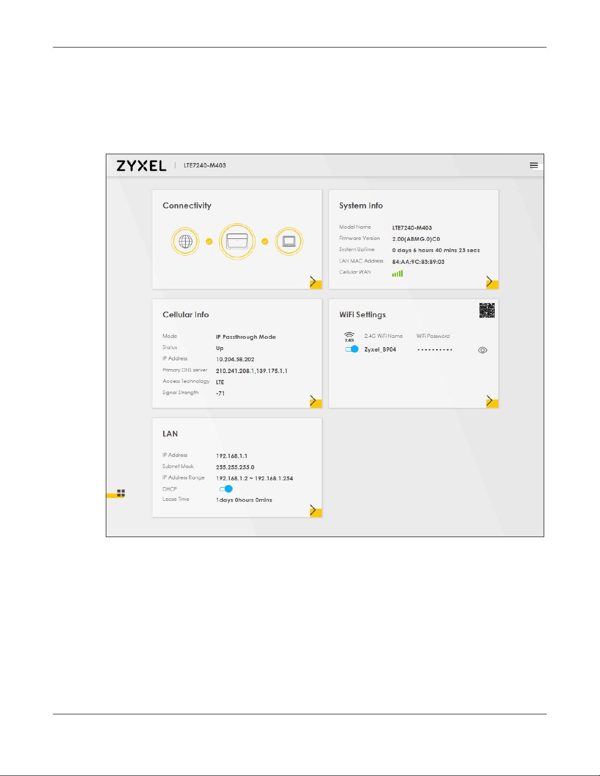
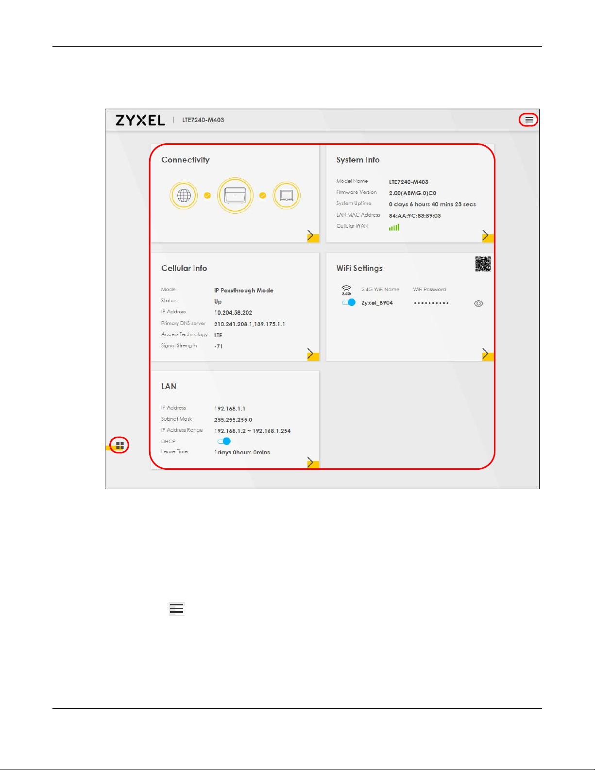
5 The Connection Status screen appears. Use this screen to configure basic Internet access, wireless
settings, and parental control settings.
Figure 16 Connection Status
LTE Series User’s Guide
26
Page 27
Chapter 2 The Web Configurator
C
A
B
2.2 Web Configurator Layout
Figure 17 Screen Layout
As illustrated above, the main screen is divided into these parts:
• A - Settings Icon (Navigation Panel & Side Bar)
• B - Widget Icon
• C - Main Window
2.2.1 Settings Icon
Click this icon ( ) to see the side bar and navigation panel.
LTE Series User’s Guide
27
Page 28
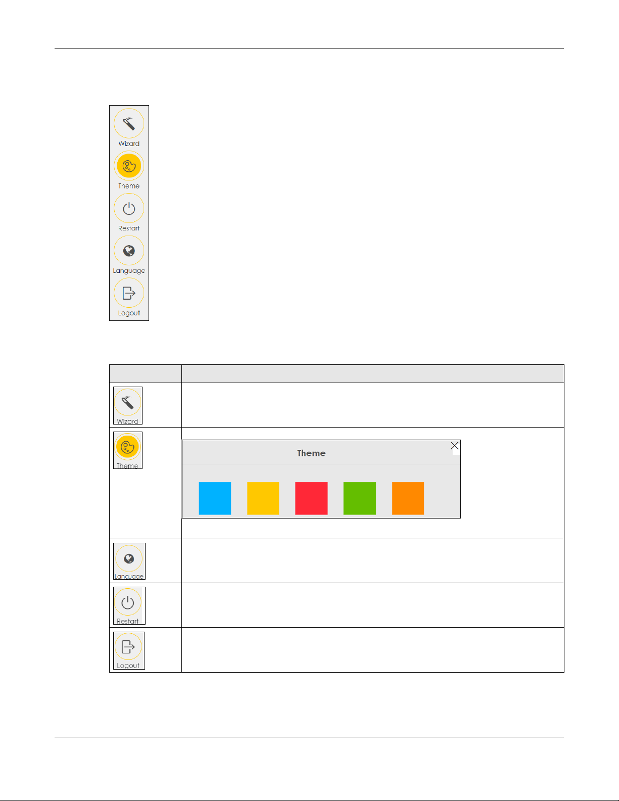
2.2.1.1 Side Bar
The side bar provides some icons on the right hand side.
Chapter 2 The Web Configurator
The icons provide the following functions.
Table 7 Web Configurator Icons in the Title Bar
ICON DESCRIPTION
Wizard: Click this icon to open screens where you can configure the Zyxel Device’s time zone
and wireless settings. See Chapter 3 on page 34 for more information about the Wizard screens.
Theme: Click this icon to select a color that you prefer and apply it to the Web Configurator.
Language: Select the language you prefer.
Restart: Click this icon to reboot the Zyxel Device without turning the power off.
Logout: Click this icon to log out of the Web Configurator.
LTE Series User’s Guide
28
Page 29
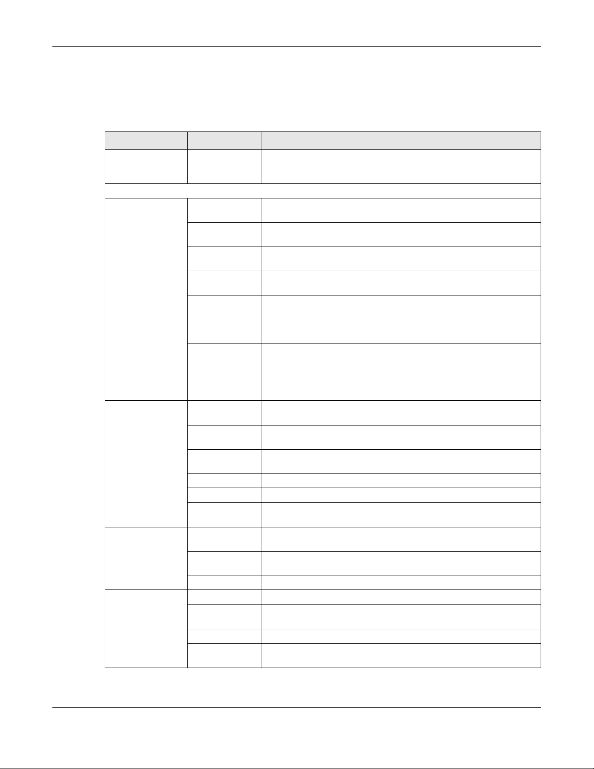
2.2.1.2 Navigation Panel
Use the menu items on the navigation panel to open screens to configure Zyxel Device features. The
following tables describe each menu item.
Table 8 Navigation Panel Summary
LINK TAB FUNCTION
Home Use this screen to configure basic Internet access and wireless settings.
Network Setting
Broadband Broadband Use this screen to view and configure ISP parameters, WAN IP address
Wireless General Use this screen to configure the wireless LAN settings and WLAN
Home
Networking
Routing Static Route Use this screen to view and set up static routes on the Zyxel Device.
Chapter 2 The Web Configurator
This screen also shows the network status of the Zyxel Device and
computers/devices connected to it.
assignment, and other advanced properties.
Ethernet WAN Use this screen to convert the fourth LAN port as WAN port, or restore the
WAN port to LAN port.
Cellular WAN Use this screen to configure an LTE WAN connection that includes the
Cellular SIM Use this screen to enter a PIN for your SIM card to prevent others from
Cellular Band Use this screen to configure the LTE frequency bands that can be used
Cellular PLMN Use this screen to view available PLMNs and select your preferred
Cellular IP
Passthrough
Access Point Name (APN) provided by your service provider.
using it.
for Internet access as provided by your service provider.
network.
Use this screen to enable IP Passthrough mode (bridge mode).
Note: This screen is not available when the fourth LAN port acts
as an Ethernet WAN port. See Table 1 on page 13 for the
feature differences of the Zyxel Devices.
authentication/security settings.
MAC
Authentication
WPS Use this screen to configure and view your WPS (WiFi Protected Setup)
WMM Use this screen to enable or disable WiFi MultiMedia (WMM).
Others Use this screen to configure advanced wireless settings.
WLAN Scheduler Use this screen to create rules to schedule the times to permit Internet
LAN Setup Use this screen to configure LAN TCP/IP settings, and other advanced
Static DHCP Use this screen to assign specific IP addresses to individual MAC
UPnP Use this screen to turn UPnP and UPnP NAT-T on or off.
DNS Route Use this screen to forward DNS queries for certain domain names through
Policy Route
RIP Use this screen to configure Routing Information Protocol to exchange
Use this screen to block or allow wireless traffic from wireless devices of
certain SSIDs and MAC addresses to the Zyxel Device.
settings.
traffic from each wireless network interfaces.
properties.
addresses.
a specific WAN interface to its DNS server(s).
Use this screen to configure policy routing on the Zyxel Device.
routing information with other routers.
LTE Series User’s Guide
29
Page 30
Chapter 2 The Web Configurator
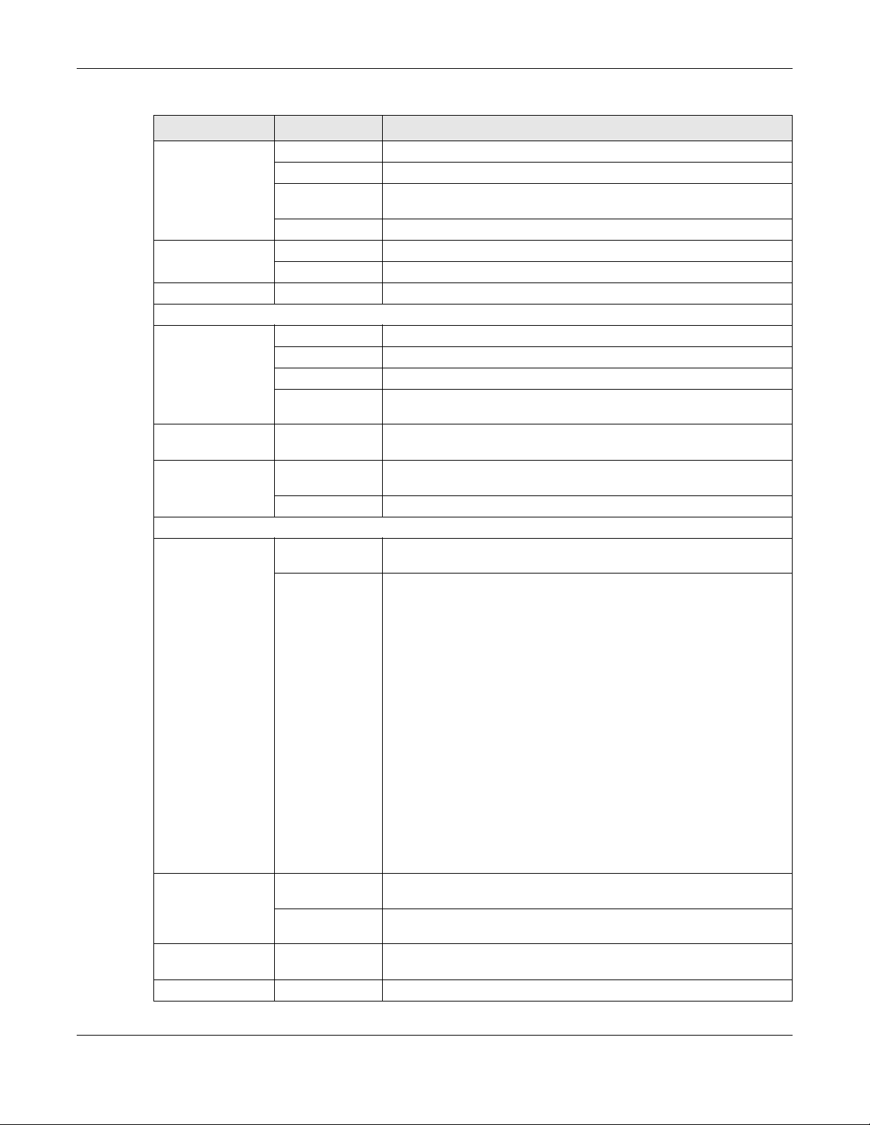
Table 8 Navigation Panel Summary (continued)
LINK TAB FUNCTION
NAT Port Forwarding Use this screen to make your local servers visible to the outside world.
Port Triggering Use this screen to change your Zyxel Device’s port triggering settings.
DMZ Use this screen to configure a default server which receives packets from
ports that are not specified in the Port Forwarding screen.
ALG Use this screen to enable or disable SIP ALG.
DNS DNS Entry Use this screen to view and configure DNS routes.
Dynamic DNS Use this screen to allow a static hostname alias for a dynamic IP address.
USB USB Service Use this screen to enable file sharing via the Zyxel Device.
Security
Firewall General Use this screen to configure the security level of your firewall.
Protocol Use this screen to add Internet services and configure firewall rules.
Access Control Use this screen to enable specific traffic directions for network services.
DoS Use this screen to activate protection against Denial of Service (DoS)
attacks.
MAC Filter MAC Filter Use this screen to block or allow traffic from devices of certain MAC
Certificates Local Certificates Use this screen to view a summary list of certificates and manage
Trusted CA
System Monitor
Log System Log Use this screen to view the status of events that occurred to the Zyxel
Security Log Use this screen to view all security related events. You can select the
addresses to the Zyxel Device.
certificates and certification requests.
Use this screen to view and manage the list of the trusted CAs.
Device. You can export or email the logs.
level and category of the security events in their proper drop-down list
window.
Levels include:
•Emergency
•Alert
• Critical
• Error
• Warning
•Notice
• Informational
•Debugging
Categories include:
• Account
• Attack
•Firewall
• MAC Filter
Traffic Status WAN Use this screen to view the status of all network traffic going through the
LAN Use this screen to view the status of all network traffic going through the
ARP table ARP table Use this screen to view the ARP table. It displays the IP and MAC address
Routing Table Routing Table Use this screen to view the routing table on the Zyxel Device.
WAN port of the Zyxel Device.
LAN ports of the Zyxel Device.
of each DHCP connection.
LTE Series User’s Guide
30
Page 31

Chapter 2 The Web Configurator
Table 8 Navigation Panel Summary (continued)
LINK TAB FUNCTION
Cellular WAN
Status
Maintenance
System System
User Account User Account Use this screen to change the user password on the Zyxel Device.
Remote
Management
TR-069 Client TR-069 Client Use this screen to configure your Zyxel Device to be managed remotely
Time Time Use this screen to change your Zyxel Device’s time and date.
Email
Notification
Log Setting Log Setting Use this screen to change your Zyxel Device’s log settings.
Firmware
Upgrade
Backup/Restore Backup/Restore Use this screen to backup and restore your Zyxel Device’s configuration
Reboot Reboot Use this screen to reboot the Zyxel Device without turning the power off.
Diagnostic Ping&Traceroute
Cellular Statistics Use this screen to look at the cellular Internet connection status.
Use this screen to set the Zyxel Device name and Domain name.
MGMT Services Use this screen to enable specific traffic directions for network services.
MGMT Services
for IP Passthrough
Trust Domain Use this screen to view a list of public IP addresses which are allowed to
Email Notification Use this screen to configure up to two mail servers and sender addresses
Firmware
Upgrade
&Nslookup
Use this screen to enable various approaches to access this Zyxel Device
remotely from a WAN and/or LAN connection.
access the Zyxel Device through the services configured in the
Maintenance > Remote Management screen.
by an Auto Configuration Server (ACS) using TR-069.
on the Zyxel Device.
Use this screen to upload firmware to your Zyxel Device.
(settings) or reset the factory default settings.
Use this screen to identify problems with the DSL connection. You can
use Ping, TraceRoute, or Nslookup to help you identify problems.
LTE Series User’s Guide
31
Page 32

2.2.2 Widget Icon
Click this icon ( ) in the lower left corner to arrange the screen order.
Chapter 2 The Web Configurator
LTE Series User’s Guide
32
Page 33

Chapter 2 The Web Configurator
Select a block and hold it to move around. Click the Check icon ( ) in the lower left corner to save
the changes.
LTE Series User’s Guide
33
Page 34

3.1 Overview
Use the Wizard screens to configure the Zyxel Device’s time zone and wireless settings.
Note: See the technical reference chapters (starting on Chapter 4 on page 37) for
background information on the features in this chapter.
3.2 Quick Start Setup
You can click the Wizard icon in the side bar to open the Wizard screens. See Section 2.2.1.1 on page 28
for more information about the side bar. After you click the Wizard icon, the following screen appears.
Click Let’s Go to proceed with settings on time zone and wireless networks. It will take you a few minutes
to complete the settings on the Wizard screens. You can click Skip to leave the Wizard screens.
CHAPTER 3
Quick Start
Figure 18 Wizard - Home
3.3 Time Zone
Select the time zone of your location. Click Next.
Figure 19 Wizard - Time Zone
LTE Series User’s Guide
34
Page 35

3.4 WiFi Setup
Turn WiFi on or off. If you keep it on, record the WiFi Name and Password in this screen so you can
configure your wireless clients to connect to the Zyxel Device. If you want to show or hide your WiFi
password, click the Eye icon ( ).
Click Done.
Figure 20 Wizard - Wireless
Chapter 3 Quick Start
Note: You can also enable the wireless service using any of the following methods:
Click Network Setting > Wireless to open the General screen. Then select Enable in the
Wireless field. Or,
Press the WiFi button located under the RESET button (see Section 1.5.4 on page 23 for
the location and for how long the wireless function is turned on) for one second.
3.5 Quick Start Setup-Finish
Your Zyxel Device saves your settings and attempts to connect to the Internet.
LTE Series User’s Guide
35
Page 36

PART II
Technical Reference
36
Page 37

Connection Status
4.1 Connection Status Overview
After you log into the Web Configurator, the Connection Status screen appears. You can configure
basic Internet access and wireless settings in this screen. It also shows the network status of the Zyxel
Device and computers/devices connected to it.
4.1.1 Connectivity
Use this screen to view the network connection status of the Zyxel Device and its clients.
Figure 21 Connectivity
CHAPTER 4
Click the Arrow icon ( ) to view IP addresses and MAC addresses of the wireless and wired devices
connected to the Zyxel Device.
Figure 22 Connectivity: Connected Devices
You can change the icon and name of a connected device. Place your mouse within the device
block, and an Edit icon ( ) will appear. Click the Edit icon, and you’ll see there are several icon
choices for you to select. Enter a name in the Device Name field for a connected device. Click to
enable
() i Internet Blocking for a connected device. Click Save to save your changes.
LTE Series User’s Guide
37
Page 38

Figure 23 Connectivity: Edit
4.1.2 System Info
Chapter 4 Connection Status
Use this screen to view the basic system information of the Zyxel Device.
Figure 24 System Info
Click the Arrow icon ( ) to view the more information on the status of your firewall and interfaces (WAN,
LAN, and WLAN).
LTE Series User’s Guide
38
Page 39

Chapter 4 Connection Status
Figure 25 System Info: Detailed Information
Each field is described in the following table.
Table 9 System Info: Detailed Information
LABEL DESCRIPTION
Host Name This field displays the Zyxel Device system name. It is used for identification.
Model Name This shows the model number of your Zyxel Device.
Serial Number This field displays the serial number of the Zyxel Device.
Firmware Version This is the current version of the firmware inside the Zyxel Device.
System Up Time This field displays how long the Zyxel Device has been running since it last started up. The
Zyxel Device starts up when you plug it in, when you restart it (Maintenance > Reboot), or
when you reset it.
Interface Status
Virtual ports are shown here. You can see the ports in use and their transmission rate.
WAN Information (These fields display when you have a WAN connection.)
Mode This field displays the current mode of your Zyxel Device.
IP Address This field displays the current IP address of the Zyxel Device in the WAN.
IP Subnet Mask This field displays the current subnet mask in the WAN.
IPv6 Address This field displays the current IPv6 address of the Zyxel Device in the WAN.
Primary DNS
server
This field displays the first DNS server address assigned by the ISP.
LTE Series User’s Guide
39
Page 40

Chapter 4 Connection Status
Table 9 System Info: Detailed Information (continued)
LABEL DESCRIPTION
Secondary DNS
server
Primary DNSv6
server
Secondary
DNSv6 server
LAN Information
IP Address This is the current IP address of the Zyxel Device in the LAN.
Subnet Mask This is the current subnet mask in the LAN.
DHCP This field displays what DHCP services the Zyxel Device is providing to the LAN. The possible
Security
Firewall This displays the firewall’s current security level.
WLAN Information
MAC Address This shows the wireless adapter MAC (Media Access Control) Address of the wireless
Status This displays whether the WLAN is activated.
SSID This is the descriptive name used to identify the Zyxel Device in a wireless LAN.
Channel This is the channel number currently used by the wireless interface.
Security This displays the type of security mode the wireless interface is using in the wireless LAN.
802.11 Mode This displays the type of 802.11 mode the wireless interface is using in the wireless LAN.
WPS This displays whether WPS is activated on the wireless interface.
This field displays the second DNS server address assigned by the ISP.
This field displays the first DNS server IPv6 address assigned by the ISP.
This field displays the second DNS server IPv6 address assigned by the ISP.
values are:
Server - The Zyxel Device is a DHCP server in the LAN. It assigns IP addresses to other
computers in the LAN.
Relay - The Zyxel Device acts as a surrogate DHCP server and relays DHCP requests and
responses between the remote server and the clients.
None - The Zyxel Device is not providing any DHCP services to the LAN.
interface.
4.1.3 Cellular Info
Use this screen to view the LTE connection details and LTE signal strength value that you can use as
reference for positioning the Zyxel Device, as well as SIM card and module information.
Figure 26 Cellular Info
LTE Series User’s Guide
40
Page 41

Chapter 4 Connection Status
Click the Arrow icon ( ) to view the more information on the LTE connection.
Figure 27 Cellular Info: Detailed Information
The following table describes the labels in this screen.
Table 10 Cellular Info: Detailed Information
LABEL DESCRIPTION
Module Information
IMEI This shows the International Mobile Equipment Identity of the Zyxel Device.
Module SW
Version
SIM Status
SIM Card Status This displays the SIM card status:
IMSI This displays the International Mobile Subscriber Identity (IMSI) of the installed SIM card. An IMSI is
ICCID
PIN Protection A PIN (Personal Identification Number) code is a key to a SIM card. Without the PIN code, you
This shows the software version of the LTE module.
None - the Zyxel Device does not detect that there is a SIM card inserted.
Available - the SIM card could either have or doesn’t have PIN code security.
Locked - the SIM card has PIN code security, but you did not enter the PIN code yet.
Blocked - you entered an incorrect PIN code too many times, so the SIM card has been locked;
call the ISP for a PUK (Pin Unlock Key) to unlock the SIM card.
Error - the Zyxel Device detected that the SIM card has errors.
a unique ID used to identify a mobile subscriber in a mobile network.
Integrated Circuit Card Identifier (ICCID). This is the serial number of the SIM card.
cannot use the SIM card.
Shows Enable if the service provider requires you to enter a PIN to use the SIM card.
Shows Disable if the service provider lets you use the SIM without inputting a PIN.
LTE Series User’s Guide
41
Page 42

Chapter 4 Connection Status
Table 10 Cellular Info: Detailed Information
LABEL DESCRIPTION
PIN Remaining
Attempts
IP Passthrough Status
IP Passthrough
Enable
IP Passthrough
Mode
Cellular Status
Cellular Status This displays the status of the cellular Internet connection.
Data Roaming This displays if data roaming is enabled on the Zyxel Device.
Operator This displays the name of the service provider.
PLMN This displays the PLMN number.
Access
Technology
Band This displays the current LTE band of your Zyxel Device (WCDMA2100).
RSSI This displays the strength of the 3G/LTE signal strength between an associated cellular station
Cell ID This shows the cell ID, which is a unique number used to identify the Base Transceiver Station to
Physical Cell ID This shows the Physical Cell ID (PCI), which are queries and replies between the Zyxel Device and
UL Bandwidth
(MHz)
DL Bandwidth
(MHz)
This is how many more times you can try to enter the PIN code before the ISP blocks your SIM
card.
This displays if IP Passthrough is enabled on the Zyxel Device.
IP Passthrough allows a LAN computer on the local network of the Zyxel Device to have access
to web services using the public IP address. When IP Passthrough is configured, all traffic is
forwarded to the LAN computer and will not go through NAT.
This displays the IP Passthrough mode.
This displays Dynamic and the Zyxel Device will allow traffic to be forwarded to the first LAN
computer requesting an IP address from the Zyxel Device.
This displays Fixed and the Zyxel Device will allow traffic to be forwarded to a specific LAN
computer on the local network of the Zyxel Device.
4G roaming is to use your Zyxel Device in an area which is not covered by your service provider.
Enable roaming to ensure that your Zyxel Device is kept connected to the Internet when you are
traveling outside the geographical coverage area of the network to which you are registered.
This displays the type of the mobile network (such as LTE, UMTS, GSM) to which the Zyxel Device is
connecting.
and the Zyxel Device.
which the Zyxel Device is connecting.
The value depends on the Current Access Technology:
• For GPRS, it is the Cell Identity as specified in 3GPP-TS.25.331.
• For UMTS, it is the Cell Identity as defined in SIB3 3GPP-TS.25.331, 3GPP-TS.24.008.
• For LTE, it is the 28-bit binary number Cell Identity as specified in SIB1 in 3GPP-TS.36.331.
The value is ‘0’ (zero) or ‘N/A’ if there is no network connection.
the mobile network it is connecting to. The normal range is 1 to 504.
This shows the LTE channel bandwidth from device to base station. According to 3GPP
specifications, the bandwidths defined by the standard are 1.4, 3, 5, 10, 15, and 20 MHz. The
wider the bandwidth the higher the throughput.
This shows the LTE channel bandwidth from base station to LTE device. According to 3GPP
specifications, the bandwidths defined by the standard are 1.4, 3, 5, 10, 15, and 20 MHz. The
wider the bandwidth the higher the throughput.
LTE Series User’s Guide
42
Page 43

Chapter 4 Connection Status
Table 10 Cellular Info: Detailed Information
LABEL DESCRIPTION
RFCN This displays the Radio Frequency Channel Number of DL carrier frequency used by the mobile
network to which the Zyxel Device is connecting.
The value depends on the Current Access Technology:
• For GPRS, it is the ARFCN (Absolute Radio-Frequency Channel Number) as specified in 3GPPTS.45.005.
• For UMTS, it is the UARFCN (UTRA Absolute Radio-Frequency Channel Number) as specified in
3GPP-TS.25.101.
• For LTE, it is the EARFCN (E-UTRA Absolute Radio-Frequency Channel Number) as specified in
3GPP-TS.36.101.
The value is ‘0’ (zero) or ‘N/A’ if there is no network connection.
RSRP This displays the Reference Signal Receive Power (RSRP), which is the average received power
of all Resource Element (RE) that carry cell-specific Reference Signals (RS) within the specified
bandwidth.
The received RSRP level of the connected E-UTRA cell, in dBm, is as specified in 3GPP-TS.36.214.
The reporting range is specified in 3GPP-TS.36.133.
An undetectable signal is indicated by the lower limit, example -140 dBm.
This parameter is for LTE only. The normal range is -30 to -140. The value is -140 if the Current
Access Technology is not LTE. The value is ‘N/A’ if there is no network connection.
RSRQ This displays the Reference Signal Receive Quality (RSRQ), which is the ratio of RSRP to the E-UTRA
carrier RSSI and indicates the quality of the received reference signal.
The received RSRQ level of the connected E-UTRA cell, in 0.1 dB, is as specified in 3GPP-TS.36.214.
An undetectable signal is indicated by the lower limit, example -240.
This parameter is for LTE only. The normal range is -30 to -240. The value is -240 if the Current
Access Technology is not LTE. The value is ‘N/A’ if there is no network connection.
RSCP This displays the Received Signal Code Power, which measures the power of channel used by
the Zyxel Device.
The received signal level, in dBm, is of the CPICH channel (Ref. 3GPP TS 25.133). An
undetectable signal is indicated by the lower limit, example -120 dBm.
This parameter is for UMTS only. The normal range is -30 to -120. The value is -120 if the Current
Access Technology is not UMTS. The value is ‘N/A’ if there is no network connection.
EcNo This displays the ratio (in dB) of the received energy per chip and the interference level.
The measured EcNo is in 0.1 dB and is received in the downlink pilot channel. An undetectable
signal is indicated by the lower limit, example -240 dB.
This parameter is for UMTS only. The normal range is -30 to -240. The value is -240 if the Current
Access Technology is not UMTS or there is no network connection.
TAC This displays the Tracking Area Code (TAC), which is used to identify the country of a mobile
subscriber.
The physical cell ID of the connected E-UTRAN cell, is as specified in 3GPP-TS.36.101.
This parameter is for LTE only. The value is ‘0’ (zero) or ‘N/A’ if the Current Access Technology is
not LTE or there is no network connection.
LAC This displays the 2-octet Location Area Code (LAC), which is used to identify a location area
within a PLMN.
The LAC of the connected cell is as defined in SIB 1 [3GPP-TS.25.331]. The concatenation of
PLMN ID (MCC+MNC) and LAC uniquely identifies the LAI (Location Area ID) [3GPP-TS.23.003].
This parameter is for UMTS or GPRS. The value is ‘0’ (zero) if the Current Access Technology is not
UMTS or GPRS. The value is ‘N/A’ if there is no network connection.
LTE Series User’s Guide
43
Page 44

Chapter 4 Connection Status
Table 10 Cellular Info: Detailed Information
LABEL DESCRIPTION
RAC
BSIC The Base Station Identity Code (BSIC), which is a code used in GSM to uniquely identify a base
SINR This displays the Signal to Interference plus Noise Ratio (SINR) in dB. This is also a measure of signal
CQI This displays the Channel Quality Indicator (CQI). It is an indicator carrying the information on
MCS MCS stands for modulation coding scheme. The base station selects MCS based on current
RI This displays the Rank Indication, one of the control information that a UE will report to eNodeB
PMI This displays the Precoding Matrix Indicator (PMI).
This displays the RAC (Routing Area Code), which is used in mobile network “packet domain
service” (PS) to identify a routing area within a location area.
In a mobile network, it uses LAC (Location Area Code) to identify the geographical location for
the old 3G voice only service, and use RAC to identify the location of data service like HSDPA or
LTE.
The RAC of the connected UTRAN cell is as defined in SIB 1 [3GPP-TS.25.331]. The concatenation
of PLMN ID (MCC+MNC), LAC, and RAC uniquely identifies the RAI (Routing Area ID) [3GPPTS.23.003].
This parameter is for UMTS or GPRS. The value is ‘0’ (zero) if the Current Access Technology is not
UMTS or GPRS. The value is ‘N/A’ if there is no network connection.
station.
This parameter is for GPRS only. The value is ‘0’ (zero) if the Current Access Technology is not
GPRS. The value is ‘N/A’ if there is no network connection.
quality and used by the UE (User Equipment) to calculate the Channel Quality Indicator (CQI)
that it reports to the network. A negative value means more noise than signal.
how good/bad the communication channel quality is.
radio conditions. The higher the MCS the more bits can be transmitted per time unit.
(Evolved Node-B) on either PUCCH (Physical Uplink Control Channel) or PUSCH (Physical Uplink
Shared Channel) based on uplink scheduling.
PMI is for transmission modes 4 (closed loop spatial multiplexing), 5 (multi-user MIMO), and 6
(closed loop spatial multiplexing using a single layer).
PMI determines how cellular data are encoded for the antennas to improve downlink rate.
4.1.4 WiFi Settings
Use this screen to enable or disable the main 2.4 GHz wireless network. When the switch turns blue
( ), the function is enabled. Otherwise, it’s not. You can use this screen or the QR code on the upper
right corner to check the SSIDs (WiFi network name) and passwords of the main wireless networks. If you
want to show or hide your WiFi passwords, click the Eye icon ( ).
LTE Series User’s Guide
44
Page 45
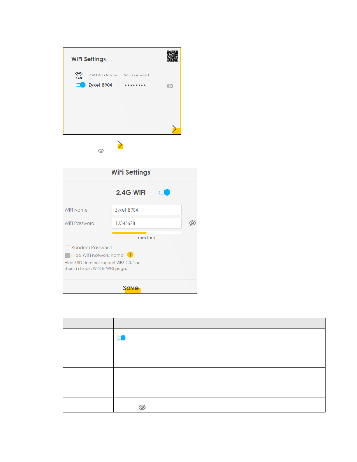
Chapter 4 Connection Status
Figure 28 WiFi Settings
Click the Arrow icon ( ) to configure the SSIDs and/or passwords for your main wireless networks. Click
the Eye icon ( ) to display the characters as you enter the WiFi Password.
Figure 29 WiFi Settings: Configuration
Each field is described in the following table.
Table 11 WiFi Settings: Configuration
LABEL DESCRIPTION
2.4G WiFi Click this switch to enable or disable the 2.4 GHz wireless network. When the switch turns blue
, the function is enabled. Otherwise, it’s not.
WiFi Name The SSID (Service Set IDentity) identifies the service set with which a wireless device is
associated. Wireless devices associating to the access point (AP) must have the same SSID.
Enter a descriptive name (up to 32 English keyboard characters) for the wireless LAN.
WiFi Password If you selected Random Password, this field displays a pre-shared key generated by the Zyxel
Device.
If you did not select Random Password, you can manually type a pre-shared key from 8 to 64
case-sensitive keyboard characters.
Click the Eye icon to show or hide the password for your wireless network. When the Eye icon
is slashed , you’ll see the password in plain text. Otherwise, it’s hidden.
LTE Series User’s Guide
45
Page 46

Table 11 WiFi Settings: Configuration (continued)
4.1.5 LAN
Use this screen to view the LAN IP address, subnet mask, and DHCP settings of your Zyxel Device.
Figure 30 LAN
Chapter 4 Connection Status
LABEL DESCRIPTION
Random Password Select this option to have the Zyxel Device automatically generate a password. The WiFi
Password field will not be configurable when you select this option.
Hide WiFi network
name
Save Click Save to save your changes.
Select this check box to hide the SSID in the outgoing beacon frame so a station cannot
obtain the SSID through scanning using a site survey tool.
Note: Disable WPS in the Network Setting > Wireless > WPS screen to hide the SSID.
Click the Arrow icon ( ) to configure the LAN IP settings and DHCP setting for your Zyxel Device.
Figure 31 LAN Setup
LTE Series User’s Guide
46
Page 47

Chapter 4 Connection Status
Each field is described in the following table.
Table 12 Status Screen
LABEL DESCRIPTION
LAN IP Setup
IP Address Enter the LAN IPv4 IP address you want to assign to your Zyxel Device in dotted decimal
Subnet Mask Type the subnet mask of your network in dotted decimal notation, for example 255.255.255.0
IP Addressing Values
Beginning IP
Address
Ending IP
Address
DHCP Server State
DHCP Server
Lease Time
Days/Hours/
Minutes
Save Click Save to save your changes.
notation, for example, 192.168.1.1 (factory default).
(factory default). Your Zyxel Device automatically computes the subnet mask based on the
IP Address you enter, so do not change this field unless you are instructed to do so.
This field specifies the first of the contiguous addresses in the IP address pool.
This field specifies the last of the contiguous addresses in the IP address pool.
This is the period of time DHCP-assigned addresses is used. DHCP automatically assigns IP
addresses to clients when they log in. DHCP centralizes IP address management on central
computers that run the DHCP server program. DHCP leases addresses, for a period of time,
which means that past addresses are “recycled” and made available for future
reassignment to other systems.
Enter the lease time of the DHCP server.
LTE Series User’s Guide
47
Page 48

5.1 Overview
This chapter discusses the Zyxel Device’s Broadband screens. Use these screens to configure your Zyxel
Device for Internet access.
A WAN (Wide Area Network) connection is an outside connection to another network or the Internet. It
connects your private networks, such as a LAN (Local Area Network) and other networks, so that a
computer in one location can communicate with computers in other locations.
Figure 32 LAN and WAN
CHAPTER 5
Broadband
5.1.1 What You Can Do in this Chapter
• Use the Broadband screen to view a WAN interface. You can also configure the WAN settings on the
Zyxel Device for Internet access (Section 5.2 on page 49).
• Use the Ethernet WAN screen to convert LAN port number four as a WAN port or restore the Ethernet
WAN port to a LAN port (Section 5.3 on page 54).
• Use the Cellular WAN screen to configure an LTE WAN connection (Section 5.4 on page 54).
• Use the Cellular SIM screen to enter the PIN of your SIM card (Section 5.5 on page 56).
• Use the Cellular Band screen to view or edit an LTE WAN interface. You can also configure the WAN
settings on the Zyxel Device for Internet access (Section 5.2 on page 49).
• Use the Cellular PLMN screen to display available Public Land Mobile Networks (Section 5.7 on page
58).
• Use the Cellular IP Passthrough screen to configure an LTE WAN connection (Section 5.8 on page 60).
LTE Series User’s Guide
48
Page 49

• Use the Cellular IP Passthrough screen to configure an LTE WAN connection (Section 5.8 on page 60).
Table 13 WAN Setup Overview
LAYER-2 INTERFACE INTERNET CONNECTION
CONNECTION DSL LINK TYPE MODE ENCAPSULATION CONNECTION SETTINGS
Ethernet
N/A
5.1.2 What You Need to Know
The following terms and concepts may help as you read this chapter.
WAN IP Address
The WAN IP address is an IP address for the Zyxel Device, which makes it accessible from an outside
network. It is used by the Zyxel Device to communicate with other devices in other networks. The ISP
dynamically assigns it each time the Zyxel Device tries to access the Internet.
APN
Chapter 5 Broadband
Routing IPoE WAN IPv4/IPv6 IP address, NAT, DNS
server and routing feature.
Access Point Name (APN) is a unique string which indicates an LTE network. An APN is required for LTE
stations to enter the LTE network and then the Internet.
5.1.3 Before You Begin
You may need to know your Internet access settings such as LTE APN, WAN IP address and SIM card’s
PIN code if the INTERNET light on your Zyxel Device is off. Get this information from your service provider.
5.2 Broadband
Use this screen to change your Zyxel Device’s Internet access settings. The summary table shows you the
configured WAN services (connections) on the Zyxel Device. Use information provided by your ISP to
configure WAN settings.
Click Network Setting > Broadband to access this screen.
LTE Series User’s Guide
49
Page 50

Chapter 5 Broadband
Figure 33 Network Setting > Broadband
The following table describes the labels in this screen.
Table 14 Network Setting > Broadband
LABEL DESCRIPTION
# This is the index number of the entry.
Name This is the service name of the connection.
Type This shows whether it is a cellular or Ethernet connection.
Mode This shows the connection is in routing mode.
Encapsulation This is the method of encapsulation used by this connection.
802.1p This indicates the 802.1p priority level assigned to traffic sent through this connection. This
displays N/A when there is no priority level assigned.
802.1q This indicates the VLAN ID number assigned to traffic sent through this connection. This displays
IGMP Proxy This shows whether the Zyxel Device act as an IGMP proxy on this connection.
NAT This shows whether NAT is activated or not for this connection.
Default
Gateway
IPv6 This shows whether IPv6 is activated or not for this connection. IPv6 is not available when the
MLD Proxy This shows whether Multicast Listener Discovery (MLD) is activated or not for this connection. MLD
Modify Click the Edit icon to configure the WAN connection.
N/A when there is no VLAN ID number assigned.
This shows whether the Zyxel Device use the WAN interface of this connection as the system
default gateway.
connection uses the bridging service.
is not available when the connection uses the bridging service.
Click the Delete icon to remove the WAN connection.
5.2.1 Add/Edit Internet Connection
Click the Edit icon next to an existing WAN interface to open the following screen. Use this screen to
configure a WAN connection.
LTE Series User’s Guide
50
Page 51
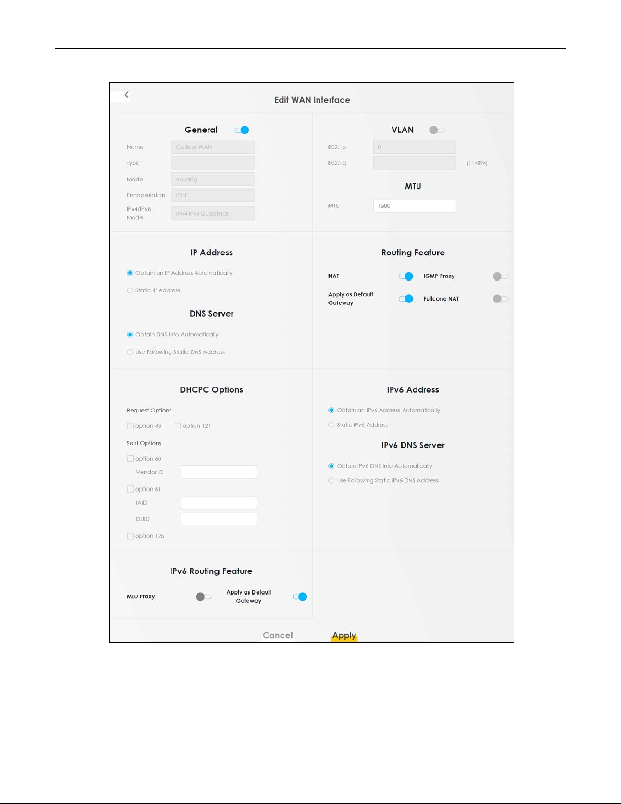
Chapter 5 Broadband
Figure 34 Network Setting > Broadband > Add/Edit New WAN Interface
LTE Series User’s Guide
51
Page 52

Chapter 5 Broadband
The following table describes the labels in this screen.
Table 15 Network Setting > Broadband > Add/Edit New WAN Interface (Routing Mode)
LABEL DESCRIPTION
General Click this switch to enable or disable the interface. When the switch goes to the right , the
Name This is the service name of the connection.
Type This shows whether it is a cellular or Ethernet connection.
Mode This shows the connection is in routing mode.
Encapsulation This is the method of encapsulation used by this connection.
IPv4/IPv6 Mode This shows IPv4 IPv6 DualStack.
VLAN Click this switch to enable or disable VLAN on this WAN interface. When the switch goes to the
802.1p IEEE 802.1p defines up to 8 separate traffic types by inserting a tag into a MAC-layer frame that
802.1q Type the VLAN ID number (from 1 to 4094) for traffic through this connection.
MTU
MTU Enter the MTU (Maximum Transfer Unit) size for this traffic.
IP Address
Obtain an IP
Address
Automatically
Static IP Address Select this option If the ISP assigned a fixed IP address.
IP Address Enter the static IP address provided by your ISP.
Subnet Mask Enter the subnet mask provided by your ISP.
Gateway IP
Address
DNS Server
Primary DNS
Server
Secondary DNS
Server
Routing Feature
NAT Click this switch to activate or deactivate NAT on this connection. When the switch goes to the
function is enabled. Otherwise, it’s not.
If the Zyxel Device is in routing mode, your ISP gives you one IP address only and you want
multiple computers to share an Internet account.
IPv4 IPv6 DualStack allows the Zyxel Device to run IPv4 and IPv6 at the same time.
right , the function is enabled. Otherwise, it’s not.
contains bits to define class of service.
Select the IEEE 802.1p priority level (from 0 to 7) to add to traffic through this connection. The
greater the number, the higher the priority level.
A static IP address is a fixed IP that your ISP gives you. A dynamic IP address is not fixed; the ISP
assigns you a different one each time you connect to the Internet. Select this if you have a
dynamic IP address.
Enter the gateway IP address provided by your ISP.
Select Obtain DNS Info Automically if you want the Zyxel Device to use the DNS server addresses
assigned by your ISP.
Select Use Following Static DNS Address if you want the Zyxel Device to use the DNS server
addresses you configure manually.
Enter the first DNS server address assigned by the ISP.
Enter the second DNS server address assigned by the ISP.
right , the function is enabled. Otherwise, it’s not.
LTE Series User’s Guide
52
Page 53

Chapter 5 Broadband
Table 15 Network Setting > Broadband > Add/Edit New WAN Interface (Routing Mode)
LABEL DESCRIPTION
IGMP Proxy Internet Group Multicast Protocol (IGMP) is a network-layer protocol used to establish
membership in a Multicast group - it is not used to carry user data.
Click this switch to have the Zyxel Device act as an IGMP proxy on this connection. When the
switch goes to the right , the function is enabled. Otherwise, it’s not.
This allows the Zyxel Device to get subscribing information and maintain a joined member list for
each multicast group. It can reduce multicast traffic significantly.
Apply as Default
Gateway
Fullcone NAT Click this switch to enable or disable full cone NAT on this connection. When the switch goes to
DHCPC Options
Request Options Select Option 43 to have the Zyxel Device automatically add vendor specific information in the
Sent Options
option 60 Select this and enter the device identity you want the Zyxel Device to add in the DHCP discovery
Vendor ID Enter the Vendor Class Identifier, such as the type of the hardware or firmware.
option 61 Select this and enter any string that identifies the device.
IAID Enter the Identity Association Identifier (IAID) of the device, for example, the WAN connection
DUID Enter the hardware type, a time value and the MAC address of the device.
option 125 Select this to have the Zyxel Device automatically generate and add vendor specific
IPv6 Address
Obtain an IPv6
Address
Automatically
Static IPv6
Address
IPv6 Address Enter an IPv6 IP address that your ISP gave to you for this WAN interface.
Prefix Length Enter the address prefix length to specify how many most significant bits in an IPv6 address
IPv6 Default
Gateway
IPv6 DNS Server
Obtain IPv6 DNS
Info
Automatically
Use Following
Static IPv6 DNS
Address
Click this switch to have the Zyxel Device use the WAN interface of this connection as the system
default gateway. When the switch goes to the right , the function is enabled. Otherwise, it’s
not.
the right , the function is enabled. Otherwise, it’s not.
This field is available only when you activate NAT.
In full cone NAT, the Zyxel Device maps all outgoing packets from an internal IP address and port
to a single IP address and port on the external network. The Zyxel Device also maps packets
coming to that external IP address and port to the internal IP address and port.
DHCP packets to request the vendor specific options from the DHCP server.
Select Option 121 to have the Zyxel Device push static routes to clients.
packets that go to the DHCP server.
index number.
parameters in the DHCP discovery packets that go to the DHCP server.
Select Obtain an IPv6 Address Automatically if you want to have the Zyxel Device use the IPv6
prefix from the connected router’s Router Advertisement (RA) to generate an IPv6 address.
Select Static IPv6 Address if you have a fixed IPv6 address assigned by your ISP. When you select
this, the following fields appear.
compose the network address.
Enter the IP address of the next-hop gateway. The gateway is a router or switch on the same
segment as your Zyxel Device's interface(s). The gateway helps forward packets to their
destinations.
Select Obtain IPv6 DNS Info Automatically to have the Zyxel Device get the IPv6 DNS server
addresses from the ISP automatically.
Select Use Following Static IPv6 DNS Address to have the Zyxel Device use the IPv6 DNS server
addresses you configure manually.
LTE Series User’s Guide
53
Page 54

Table 15 Network Setting > Broadband > Add/Edit New WAN Interface (Routing Mode)
LABEL DESCRIPTION
Primary DNS
Server
Secondary DNS
Server
IPv6 Routing Feature
MLD Proxy
Enable
Apply as Default
Gateway
Cancel Click Cancel to exit this screen without saving.
Apply Click Apply to save your changes.
Enter the first IPv6 DNS server address assigned by the ISP.
Enter the second IPv6 DNS server address assigned by the ISP.
Select this check box to have the Zyxel Device act as an MLD proxy on this connection. This
allows the Zyxel Device to get subscription information and maintain a joined member list for
each multicast group. It can reduce multicast traffic significantly.
Select this option to have the Zyxel Device use the WAN interface of this connection as the
system default gateway.
5.3 Ethernet WAN
Use this screen to have the forth LAN port act as an Ethernet WAN port. You can restore it back from a
WAN port to a LAN port. Click the switch to set up the configuration. When the switch goes to the right,
the forth LAN port act as an Ethernet WAN port. Otherwise, the forth LAN port remains as a LAN port.
Click Apply to save your changes back to the Zyxel Device.
Chapter 5 Broadband
Click Network Setting > Broadband > Ethernet WAN to display the following screen.
Figure 35 Network Setting > Broadband > Ethernet WAN
5.4 Cellular WAN
Click Network Setting > Broadband > Cellular WAN to display the following screen. Configure an LTE
connection, including the Access Point Name (APN) provided by your service provider.
LTE Series User’s Guide
54
Page 55

Chapter 5 Broadband
Note: APN information can be obtained from the service provider.
Roaming charges may apply when Data Roaming is enabled.
Automatic APN Mode is not supported when operating in 3G only mode.
Figure 36 Network Setting > Broadband > Cellular WAN
The following table describes the fields in this screen.
Table 16 Network Setting > Broadband > Cellular WAN
LABEL DESCRIPTION
Roaming
Data Roaming Click this to enable ( ) data roaming on the Zyxel Device.
4G roaming is to use your mobile device in an area which is not covered by your service provider.
Enable roaming to ensure that your Zyxel Device is kept connected to the Internet when you are
traveling outside the geographical coverage area of the network to which you are registered.
APN Settings
APN Manual
Mode
APN This field allows you to display the Access Point Name (APN) in the profile.
Username This field allows you to display the user name in the profile.
Disable this to have the Zyxel Device configure the APN (Access Point Name) of an LTE network
automatically. Otherwise, Click this to enable ( ) and enter the APN manually in the field
below.
Enter the Access Point Name (APN) provided by your service provider. Connections with different
APNs may provide different services (such as Internet access or MMS (Multi-Media Messaging
Service)) and charging method.
You can enter up to 30 printable ASCII characters. Spaces are allowed.
Type the user name (up to 31 printable ASCII characters) given to you by your service provider.
LTE Series User’s Guide
55
Page 56

Chapter 5 Broadband
Table 16 Network Setting > Broadband > Cellular WAN (continued)
LABEL DESCRIPTION
Password This field allows you to set the password in the profile.
Type the password (up to 31 printable ASCII characters) associated with the user name above.
Authentication
Type
PDP Type Select IPv4 if you want the Zyxel Device to run IPv4 (Internet Protocol version 4 addressing system)
Apply Click this to save your changes.
Cancel Click this to exit this screen without saving.
Select the type of authentication method peers use to connect to the Zyxel Device in LTE
connections.
In Password Authentication Protocol (PAP) peers identify themselves with a user name and
password. In Challenge Handshake Authentication Protocol (CHAP) additionally to user name
and password the Zyxel Device sends regular challenges to make sure an intruder has not
replaced a peer. Otherwise select PAP/CHAP or None.
only.
Select IPv4/IPv6 if you want the Zyxel Device to run both IPv4 and IPv6 (Internet Protocol version 4
and 6 addressing system) at the same time.
5.5 Cellular SIM Configuration
Enter a PIN for your SIM card to prevent others from using it.
Entering the wrong PIN code 3 consecutive times locks the SIM card
after which you need a PUK (Personal Unlocking Key) from the service
provider to unlock it.
Click Network Setting > Broadband > Cellular SIM. The following screen opens.
Figure 37 Network Setting > Broadband > Cellular SIM
Note: The PIN is automatically saved in the Zyxel Device.
Entering the wrong PIN exceeding a set number of times will lock the SIM card.
LTE Series User’s Guide
56
Page 57

Chapter 5 Broadband
The following table describes the fields in this screen.
Table 17 Network Setting > Broadband > Cellular SIM
LABEL DESCRIPTION
PIN Management
PIN Protection A PIN (Personal Identification Number) code is a key to a SIM card. Without the PIN code, you
PIN If you enabled PIN verification, enter the 4-digit PIN code (0000 for example) provided by your ISP.
Attempts
Remaining
Apply Click Apply to save your changes.
Cancel Click Cancel to return to the previous screen without saving.
cannot use the SIM card.
Click to enable ( ) if the service provider requires you to enter a PIN to use the SIM card.
Click to disable if the service provider lets you use the SIM without inputting a PIN.
If you enter the PIN code incorrectly too many times, the ISP may block your SIM card and not let
you use the account to access the Internet.
This is how many more times you can try to enter the PIN code before the ISP blocks your SIM card.
5.6 Cellular Band Configuration
Either select Auto to have the Zyxel Device connect to an available network using the default settings
on the SIM card or select the type of the network (4G, 3G, or 2G) to which you want the Zyxel Device to
connect.
Click Network Setting > Broadband > Cellular Band. The following screen opens.
Figure 38 Network Setting > Broadband > Cellular Band
LTE Series User’s Guide
57
Page 58

Chapter 5 Broadband
The following table describes the fields in this screen.
Table 18 Network Setting > Broadband > Cellular Band
LABEL DESCRIPTION
Access Technology
Preferred Access
Technology
Band Management
Band Auto Selection Select the LTE bands to use for the Zyxel Device’s WAN connection. Click to enable ( )
Apply Click this to save your changes.
Cancel Click this to exit this screen without saving.
Select the type of the network (4G, 3G, or 2G) to which you want the Zyxel Device to
connect and click Apply to save your settings.
Otherwise, select Auto to have the Zyxel Device connect to an available network using the
default settings on the SIM card. If the currently registered mobile network is not available or
the mobile network’s signal strength is too low, the Zyxel Device switches to another
available mobile network.
automatic LTE frequency band selection as provided by your service provider. Otherwise,
select disabled.
5.7 PLMN Configuration
Each service provider has its own unique Public Land Mobile Network (PLMN) number. Either select PLMN
Auto Selection to have the Zyxel Device connect to the service provider using the default settings on the
SIM card or manually view available PLMNs and select your service provider.
Click Network Setting > Broadband > Cellular PLMN. The screen appears as shown next.
Figure 39 Network Setting > Broadband > Cellular PLMN
The following table describes the labels in this screen.
Table 19 Network Setting > Broadband > Cellular PLMN
LABEL DESCRIPTION
PLMN Management
PLMN Auto Selection Click to enable ( ) and have the Zyxel Device automatically connect to the first
available mobile network.
Select disabled to display the network list and manually select a preferred network.
Apply Click Apply to save your changes back to the Zyxel Device.
Cancel Click Cancel to exit this screen without saving.
After selecting to disable the following warning appears. Click OK to continue.
LTE Series User’s Guide
58
Page 59

Chapter 5 Broadband
Figure 40 Network Setting > Broadband > Cellular PLMN > Manual Scan Warning
When the next screen appears, clicking Scan will allow the Zyxel Device to check for available PLMNs in
its surroundings and display the network list.
Figure 41 Network Setting > Broadband > Cellular PLMN > Manual Scan
LTE Series User’s Guide
59
Page 60
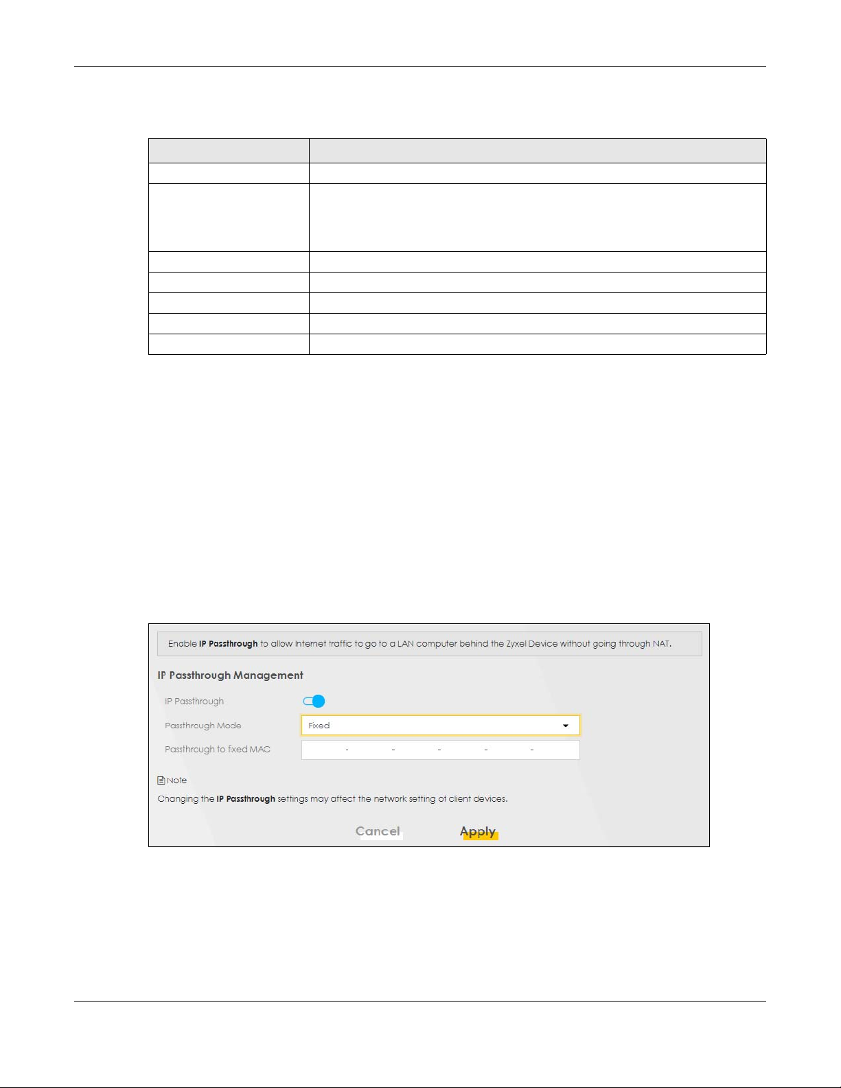
The following table describes the labels in this screen.
Table 20 Network Setting > Broadband > Cellular PLMN > Manual Scan
LABEL DESCRIPTION
# Click the radio button so the Zyxel Device connects to this ISP.
Status This shows Current to show the ISP the Zyxel Device is currently connected to.
Name This shows the ISP name.
Type This shows the type of network the ISP provides.
PLMN This shows the PLMN number.
Apply Click Apply to save your changes back to the Zyxel Device.
Cancel Click Cancel to exit this screen without saving.
Select from the network list and click Apply.
5.8 IP Passthrough
Chapter 5 Broadband
This shows Forbidden to indicate the Zyxel Device cannot connect to this ISP.
This shows Available to indicate an available ISP your Zyxel Device can connect to.
Enable IP Passthrough to allow Internet traffic to go to a LAN computer behind the Zyxel Device without
going through NAT.
Click Network Setting > Broadband > Cellular IP Passthrough to display the following screen.
Note: This screen is not available when the fourth LAN port acts as an Ethernet WAN port. See
Table 1 on page 13 for the feature differences of the Zyxel Devices.
Figure 42 Network Setting > Broadband > Cellular IP Passthrough
Note: Changing the IP Passthrough settings may affect the network setting of client devices.
After selecting to enable the following warning appears. Click OK to continue.
LTE Series User’s Guide
60
Page 61

Chapter 5 Broadband
Figure 43 Network Setting > Broadband > Cellular IP Passthrough > Enable Warning
The following table describes the fields in this screen.
Table 21 Network Setting > Broadband > IP Passthrough
LABEL DESCRIPTION
IP Passthrough Management
IP Passthrough IP Passthrough allows a LAN computer on the local network of the Zyxel Device to have access to
web services using the public IP address. When IP Passthrough is configured, all traffic is forwarded
to the LAN computer and will not go through NAT.
Passthrough
Mode
Select Dynamic to allow traffic to be forwarded to any LAN computer on the local network of the
Zyxel Device. Select Fixed to allow traffic to be forwarded to a specific LAN computer on the local
network of the Zyxel Device.
Note: This field will show upon enabling IP Passthrough in the previous field.
Passthrough
to fixed MAC
Enter the MAC address of a LAN computer on the local network of the Zyxel Device upon
selecting Fixed in the previous field.
Note: This field will show upon selecting Fixed in the previous field.
Apply Click this to save your changes.
Cancel Click this to exit this screen without saving.
LTE Series User’s Guide
61
Page 62

6.1 Overview
This chapter describes the Zyxel Device’s Network Setting > Wireless screens. Use these screens to set up
your Zyxel Device’s WiFi network and security settings.
6.1.1 What You Can Do in this Chapter
This section describes the Zyxel Device’s Wireless screens. Use these screens to set up your Zyxel Device’s
WiFi connection.
• Use the General screen to enable the Wireless LAN, enter the SSID and select the WiFi security mode
(Section 6.2 on page 63).
• Use the MAC Authentication screen to allow or deny wireless clients based on their MAC addresses
from connecting to the Zyxel Device (Section 6.3 on page 66).
• Use the WPS screen to enable or disable WPS, view or generate a security PIN (Personal Identification
Number) (Section 6.4 on page 68).
• Use the WMM screen to enable WiFi MultiMedia (WMM) to ensure quality of service in WiFi networks for
multimedia applications (Section 6.5 on page 70).
• Use the Others screen to configure WiFi advanced features, such as the RTS/CTS Threshold (Section 6.6
on page 71).
• Use the WLAN Scheduler screen to create rules to schedule the times to permit Internet traffic from
each wireless network interfaces (Section 6.7 on page 73).
CHAPTER 6
Wireless
6.1.2 What You Need to Know
Wireless Basics
“Wireless” is essentially radio communication. In the same way that walkie-talkie radios send and
receive information over the airwaves, wireless networking devices exchange information with one
another. A wireless networking device is just like a radio that lets your computer exchange information
with radios attached to other computers. Like walkie-talkies, most wireless networking devices operate
at radio frequency bands that are open to the public and do not require a license to use. However,
wireless networking is different from that of most traditional radio communications in that there are a
number of wireless networking standards available with different methods of data encryption.
Finding Out More
See Section 6.8 on page 75 for advanced technical information on WiFi networks.
LTE Series User’s Guide
62
Page 63

6.2 General Settings
A WiFi network name (also known as SSID) and a security level are basic elements of a WiFi network. Set
a Security Level to protect your data from unauthorized access or damage via WiFi. Use this screen to
enable WiFi, enter the SSID and select the WiFi security mode. It’s recommended that you select More
Secure to enable WPA2-PSK data encryption.
Note: If you are configuring the Zyxel Device from a computer connected to WiFi and you
change the Zyxel Device’s SSID, channel or security settings, you will lose your
connection when you press Apply to confirm. You must then change the
your computer to match the Zyxel Device’s new settings.
Click Network Setting > Wireless to open the General screen.
Figure 44 Network Setting > Wireless > General
Chapter 6 Wireless
WiFi
WiFi settings of
LTE Series User’s Guide
63
Page 64

Chapter 6 Wireless
The following table describes the general wireless LAN labels in this screen.
Table 22 Network Setting > Wireless > General
LABEL DESCRIPTION
WiFi Network Setup
Band This shows the WiFi band which this radio profile is using. 2.4GHz is the frequency used by IEEE
WiFi Click Enable to enable the wireless LAN in this field.
Channel Use Auto to have the Zyxel Device automatically determine a channel to use.
Bandwidth Select whether the Zyxel Device uses a WiFi channel width of 20MHz, 40MHz or 20/40MHz.
Control
Sideband
WiFi Network Settings
WiFi Network
Name
802.11b/g/n WiFi clients while 5GHz is used by IEEE 802.11a/ac WiFi clients.
A standard 20MHz channel offers transfer speeds of up to 150Mbps whereas a 40MHz channel
uses two standard channels and offers speeds of up to 300Mbps.
40MHz (channel bonding or dual channel) bonds two adjacent radio channels to increase
throughput. The WiFi clients must also support 40MHz. It is often better to use the 20MHz setting in
a location where the environment hinders the
Select 20MHz if you want to lessen radio interference with other
neighborhood or the
This is available for some regions when you select a specific channel and set the Bandwidth field
to 40MHz. Set whether the control channel (set in the Channel field) should be in the Lower or
Upper range of channel bands.
The SSID (Service Set IDentity) identifies the service set with which a WiFi device is associated.
WiFi clients do not support channel bonding.
WiFi signal.
WiFi devices in your
WiFi devices associating to the access point (AP) must have the same SSID.
Max Clients Specify the maximum number of clients that can connect to this network at the same time.
Hide SSID Select this check box to hide the SSID in the outgoing beacon frame so a station cannot obtain
Multicast
Forwarding
BSSID This shows the MAC address of the wireless interface on the Zyxel Device when wireless LAN is
Security Level
Security Mode Select More Secure (WPA2-PSK) to add security on this WiFi network. The WiFi clients which want
Cancel Click Cancel to restore your previously saved settings.
Apply Click Apply to save your changes.
6.2.1 No Security
Enter a descriptive name (up to 32 English keyboard characters) for the wireless LAN.
the SSID through scanning using a site survey tool.
This check box is grayed out if the WPS function is enabled in the Network > Wireless > WPS
screen.
Select this check box to allow the Zyxel Device to convert wireless multicast traffic into wireless
unicast traffic.
enabled.
to associate to this network must have the same
you select to use a security, additional options appears in this screen.
Or you can select No Security to allow any client to associate with this network without any data
encryption or authentication.
See the following sections for more details about this field.
WiFi security settings as the Zyxel Device. When
Select No Security to allow wireless stations to communicate with the access points without any data
encryption or authentication.
LTE Series User’s Guide
64
Page 65

Note: If you do not enable any WiFi security on your Zyxel Device, your network is accessible to
any wireless networking device that is within range.
Figure 45 Wireless > General: No Security
The following table describes the labels in this screen.
Table 23 Wireless > General: No Security
LABEL DESCRIPTION
Security Level Choose No Security to allow all WiFi connections without data encryption or authentication.
6.2.2 More Secure (WPA2-PSK)
The WPA2-PSK security mode is a newer, more robust version of the WPA encryption standard. It offers
slightly better security, although the use of PSK makes it less robust than it could be. Using a Pre-Shared
Key (PSK), both the Zyxel Device and the connecting client share a common password in order to
validate the connection.
Chapter 6 Wireless
Click Network Setting > Wireless to display the General screen. Select More Secure as the security level.
WPA2-PSK is the default Security Mode.
Figure 46 Wireless > General: More Secure: WPA2-PSK
LTE Series User’s Guide
65
Page 66

Chapter 6 Wireless
The following table describes the labels in this screen.
Table 24 Wireless > General: More Secure: WPA2-PSK
LABEL DESCRIPTION
Security Level Select More Secure to enable WPA2-PSK data encryption.
Security Mode WPA2-PSK is the default security mode.
Generate
password
automatically
Password Select Generate password automatically or enter a Password.
Select this option to have the Zyxel Device automatically generate a password. The password
field will not be configurable when you select this option.
The password has two uses.
1. Manual. Manually enter the same password on the Zyxel Device and the client. Enter 8-63
ASCII characters or exactly 64 hexadecimal (‘0-9’, ‘a-f’) characters.
2. WPS. When using WPS, the Zyxel Device sends this password to the client.
Note: Enter 8-63 ASCII characters only. 64 hexadecimal characters are not accepted
for WPS.
Click the Eye icon to show or hide the password for your wireless network. When the Eye icon is
slashed , you’ll see the password in plain text. Otherwise, it’s hidden.
more... Click this to show more fields in this section. Click this to hide them.
Encryption AES is the default data encryption type, which uses a 128-bit key.
Timer This is the rate at which the RADIUS server sends a new group key out to all clients.
6.3 MAC Authentication
Configure the Zyxel Device to give exclusive access to specific devices (Allow) or exclude specific
devices from accessing the Zyxel Device (Deny) based on the device(s) MAC address. Every Ethernet
device has a unique MAC (Media Access Control) address. It is assigned at the factory and consists of
six pairs of hexadecimal characters; for example, 00:A0:C5:00:00:02. You need to know the MAC
addresses of the device(s) you want to allow/deny to configure this screen. Edit the list in the table to
decide the rule of access on device(s).
LTE Series User’s Guide
66
Page 67

Chapter 6 Wireless
Use this screen to view your Zyxel Device’s MAC filter settings and add new MAC filter rules. Click
Network Setting > Wireless > MAC Authentication. The screen appears as shown.
Figure 47 Network Setting> Wireless > MAC Authentication
The following table describes the labels in this screen.
Table 25 Network Setting> Wireless > MAC Authentication
LABEL DESCRIPTION
General
SSID Select the SSID for which you want to configure MAC filter settings.
MAC Restrict
Mode
MAC address List
Define the filter action for the list of MAC addresses in the MAC Address table.
Select Disable to turn off MAC filtering.
Select Deny to block access to the Zyxel Device. MAC addresses not listed will be allowed to
access the Zyxel Device.
Select Allow to permit access to the Zyxel Device. MAC addresses not listed will be denied
access to the Zyxel Device.
LTE Series User’s Guide
67
Page 68

Chapter 6 Wireless
Table 25 Network Setting> Wireless > MAC Authentication (continued)
LABEL DESCRIPTION
Add new MAC
address
# This is the index number of the entry.
MAC Address This is the MAC addresses of the WiFi devices that are allowed or denied access to the Zyxel
Modify Click the Edit icon and type the MAC address of the peer device in a valid MAC address format
Cancel Click Cancel to exit this screen without saving.
Apply Click Apply to save your changes.
This field is available when you select Deny or Allow in the MAC Restrict Mode field.
Click this if you want to add a new MAC address entry to the MAC filter list below.
Enter the MAC addresses of the
Device in these address fields. Enter the MAC addresses in a valid MAC address format, that is,
six hexadecimal character pairs, for example, 12:34:56:78:9a:bc.
Figure 48 Add New MAC Address
Device.
(six hexadecimal character pairs, for example 12:34:56:78:9a:bc).
Click the Delete icon to delete the entry.
WiFi devices that are allowed or denied access to the Zyxel
6.4 WPS
Use this screen to configure WiFi Protected Setup (WPS) on your Zyxel Device.
WiFi Protected Setup (WPS) allows you to quickly set up a WiFi network with strong security, without
having to configure security settings manually. Select one of the WPS methods and follow the
instructions to establish a WPS connection. To set up a WPS connection between two devices, both
devices must support WPS. It is recommended to use the Push Button Configuration (PBC) method if your
WiFi client supports it. See Section 6.8.7.3 on page 83 for more information about WPS.
Note: The Zyxel Device uses the security settings of the SSID1 profile (see Section 6.2.2 on page
Note: The WPS button will gray-out when wireless LAN or WPS is disabled.
Click Network Setting > Wireless > WPS. The following screen displays. Click this switch and it will turn blue.
Click Apply to activate the WPS function. Then you can configure the WPS settings in this screen.
65).
If WPS is enabled, UPnP will automatically be turned on.
LTE Series User’s Guide
68
Page 69

Chapter 6 Wireless
Figure 49 Network Setting > Wireless > WPS
The following table describes the labels in this screen.
Table 26 Network Setting > Wireless > WPS
LABEL DESCRIPTION
General
WPS Click to enable ( ) and have the Zyxel Device activate WPS. Otherwise, it is disabled.
Add a new device with WPS Method
Method 1 PBC Use this section to set up a WPS WiFi network using Push Button Configuration (PBC). Click this
WPS Click this button to add another WPS-enabled WiFi device (within WiFi range of the Zyxel
switch to make it turn blue. Click Apply to activate WPS method 1 on the Zyxel Device.
Device) to your WiFi network. This button may either be a physical button on the outside of a
device, or a menu button similar to the WPS button on this screen.
Note: You must press the other WiFi device’s WPS button within two minutes of
pressing this button.
Method 2 PIN Use this section to set up a WPS WiFi network by entering the PIN of the client into the Zyxel
Device. Click this switch to make it turn blue. Click Apply to activate WPS method 2 on the Zyxel
Device.
LTE Series User’s Guide
69
Page 70

Chapter 6 Wireless
Table 26 Network Setting > Wireless > WPS (continued)
LABEL DESCRIPTION
Register Enter the PIN of the device that you are setting up a WPS connection with and click Register to
authenticate and add the WiFi device to your WiFi network.
You can find the PIN either on the outside of the device, or by checking the device’s settings.
Note: You must also activate WPS on that device within two minutes to have it
present its PIN to the Zyxel Device.
Method 3 Use this section to set up a WPS WiFi network by entering the PIN of the Zyxel Device into the
client. Click this switch to make it turn blue. Click Apply to activate WPS method 3 on the Zyxel
Device.
Release
Configuration
Generate
New PIN
Cancel Click Cancel to restore your previously saved settings.
Apply Click Apply to save your changes.
The default WPS status is configured.
Click this button to remove all configured WiFi and WiFi security settings for WPS connections on
the Zyxel Device.
If this method has been enabled, the PIN (Personal Identification Number) of the Zyxel Device is
shown here. Enter this PIN in the configuration utility of the device you want to connect to using
WPS.
The PIN is not necessary when you use the WPS push-button method.
Click the Generate New PIN button to have the Zyxel Device create a new PIN.
6.5 WMM
Enable WiFi MultiMedia (WMM) and WMM Automatic Power Save (APSD) in WiFi networks for delaysensitive multimedia applications. WMM enhances data transmission quality which allows delay-sensitive
applications, such as videos, to run more smoothly. APSD improves power management of WiFi mobile
clients. APSD works only if the WiFi device to which the Zyxel Device is connected also supports this
feature.
Click Network Setting > Wireless > WMM to display the following screen.
Figure 50 Network Setting > Wireless > WMM
Note: WMM cannot be disabled if 802.11 mode includes 802.11n or 802.11ac.
LTE Series User’s Guide
70
Page 71

Chapter 6 Wireless
The following table describes the labels in this screen.
Table 27 Network Setting > Wireless > WMM
LABEL DESCRIPTION
WMM of SSID1~4 Select On to have the Zyxel Device automatically give the WiFi network (SSIDx) a priority level
WMM
Automatic
Power Save
Delivery (APSD)
according to the ToS value in the IP header of packets it sends. WMM QoS (
Quality of Service) gives high priority to video, which makes them run more smoothly.
If the 802.11 Mode in Network Setting > Wireless > Others is set to include 802.11n or 802.11ac,
WMM cannot be disabled.
Select this option to extend the battery life of your mobile devices (especially useful for small
devices that are running multimedia applications). The Zyxel Device goes to sleep mode to save
power when it is not transmitting data. The AP buffers the packets sent to the Zyxel Device until
the Zyxel Device "wakes up." The Zyxel Device wakes up periodically to check for incoming
data.
WiFi MultiMedia
Note: This works only if the WiFi device to which the Zyxel Device is connected also
supports this feature.
Cancel Click Cancel to restore your previously saved settings.
Apply Click Apply to save your changes.
6.6 Others Settings
Use this screen to change the default advanced WiFi settings. See the User's Guide for field details. Click
Network Setting > Wireless > Others. The screen appears as shown.
See Section 6.8.2 on page 77 for detailed definitions of the terms listed here.
Figure 51 Network Setting > Wireless > Others
LTE Series User’s Guide
71
Page 72

Chapter 6 Wireless
The following table describes the labels in this screen.
Table 28 Network Setting > Wireless > Others
LABEL DESCRIPTION
RTS/CTS
Threshold
Fragmentation
Threshold
Output Power Set the output power of the Zyxel Device. If there is a high density of APs in an area, decrease
Beacon Interval When a wirelessly networked device sends a beacon, it includes with it a beacon interval. This
DTIM Interval Delivery Traffic Indication Message (DTIM) is the time period after which broadcast and
802.11 Mode For 2.4GHz frequency WLAN devices:
Data with its frame size larger than this value will perform the RTS (Request To Send)/CTS (Clear
To Send) handshake.
Enter a value between 0 and 2347.
This is the maximum data fragment size that can be sent. Enter a value between 256 and 2346.
the output power to reduce interference with other APs. Select one of the following: 20%, 40%,
60%, 80% or 100%.
specifies the time period before the device sends the beacon again.
The interval tells receiving devices on the network how long they can wait in low power mode
before waking up to handle the beacon. This value can be set from 50ms to 1000ms. A high
value helps save current consumption of the access point.
multicast packets are transmitted to mobile clients in the Power Saving mode. A high DTIM
value can cause clients to lose connectivity with the network. This value can be set from 1 to
255.
•Select 802.11b Only to allow only IEEE 802.11b compliant WLAN devices to associate with
the Zyxel Device.
•Select 802.11g Only to allow only IEEE 802.11g compliant WLAN devices to associate with
the Zyxel Device.
•Select 802.11n Only to allow only IEEE 802.11n compliant WLAN devices to associate with
the Zyxel Device.
•Select 802.11b/g Mixed to allow either IEEE 802.11b or IEEE 802.11g compliant WLAN
devices to associate with the Zyxel Device. The transmission rate of your Zyxel Device might
be reduced.
•Select 802.11b/g/n Mixed to allow IEEE 802.11b, IEEE 802.11g or IEEE802.11n compliant
WLAN devices to associate with the Zyxel Device. The transmission rate of your Zyxel Device
might be reduced.
For 5GHz frequency WLAN devices:
•Select 802.11a Only to allow only IEEE 802.11a compliant WLAN devices to associate with
the Zyxel Device.
•Select 802.11n Only to allow only IEEE 802.11n compliant WLAN devices to associate with
the Zyxel Device.
•Select 802.11ac Only to allow only IEEE 802.11ac compliant WLAN devices to associate with
the Zyxel Device.
•Select 802.11a/n Mixed to allow either IEEE 802.11a or IEEE 802.11n compliant WLAN devices
to associate with the Zyxel Device. The transmission rate of your Zyxel Device might be
reduced.
•Select 802.11n/ac Mixed to allow either IEEE 802.11n or IEEE 802.11ac compliant WLAN
devices to associate with the Zyxel Device. The transmission rate of your Zyxel Device might
be reduced.
•Select 802.11a/n/ac Mixed to allow IEEE 802.11a, IEEE 802.11n or IEEE802.11ac compliant
WLAN devices to associate with the Zyxel Device. The transmission rate of your Zyxel Device
might be reduced.
802.11 Protection Enabling this feature can help prevent collisions in mixed-mode networks (networks with both
IEEE 802.11b and IEEE 802.11g traffic).
Select Auto to have the wireless devices transmit data after a RTS/CTS handshake. This helps
improve IEEE 802.11g performance.
Select Off to disable 802.11 protection. The transmission rate of your Zyxel Device might be
reduced in a mixed-mode network.
This field displays Off and is not configurable when you set 802.11 Mode to 802.11b Only.
LTE Series User’s Guide
72
Page 73

Table 28 Network Setting > Wireless > Others (continued)
LABEL DESCRIPTION
Preamble Select a preamble type from the drop-down list box. Choices are Long or Short. See Section
6.8.6 on page 80 for more information.
This field is configurable only when you set 802.11 Mode to 802.11b.
Protected
Management
Frames
Cancel Click Cancel to restore your previously saved settings.
Apply Click Apply to save your changes.
WiFi with Protected Management Frames (PMF) provides protection for unicast and multicast
management action frames. Unicast management action frames are protected from both
eavesdropping and forging, and multicast management action frames are protected from
forging. Select Capable if the WiFi client supports PMF, then the management frames will be
encrypted. Select Required to force the WiFi client to support PMF; otherwise the
authentication cannot be performed by the Zyxel Device. Otherwise, select Disabled.
6.7 WLAN Scheduler
Use the WLAN Scheduler screen to create rules to schedule the times to permit wireless connections.
Select a specific time and day of a week for scheduling. You can also create a rule to automatically
switch off all the WLAN together.
Chapter 6 Wireless
Click Network Setting > Wireless > WLAN Scheduler.
Figure 52 Network Setting > Wireless > WLAN Scheduler
The following table describes the labels in this screen.
Table 29 Network Setting > Wireless > WLAN Scheduler
LABEL DESCRIPTION
WLAN Scheduler
Access
Add New Rule Click this to configure a new WLAN scheduler rule.
# This is the index number of the entry.
Click this switch to enable the WLAN scheduler function. This serves as the main switch to
allow the individual rules to function. When the switch turns blue , the function is enabled.
Otherwise, it’s not.
LTE Series User’s Guide
73
Page 74

Table 29 Network Setting > Wireless > WLAN Scheduler (continued)
LABEL DESCRIPTION
Active Click the check box to enable individual rules.
Rule Name This field displays the name of the rule.
SSID This is the descriptive name used to identify the wireless network interface that this rule applies
Day This field displays the day(s) of the week that you wish to apply this rule.
Time This field displays the time of the day that you wish to apply this rule.
Description This field shows a description of the rule, usually to help identify it.
Modify Click the Edit icon to configure the connection.
Note: If you enable a rule for a specific SSID, you will not be able to connect to other wireless
networks.
6.7.1 Add/Edit Rules
Chapter 6 Wireless
Note: Make sure to enable the WLAN Scheduler Access switch for the individual
rules to work.
to. Will show ALL WLAN if you select All wireless networks in the Add New Rule screen.
Click the Delete icon to remove the rule.
Click Add New Rule in the WLAN Scheduler screen, or click the Edit icon next to a scheduling rule, and
the following screen displays.
Use this screen to create a scheduling rule to permit wireless connections.
Figure 53 Network Setting > Wireless > WLAN Scheduler > Add New Rule
LTE Series User’s Guide
74
Page 75

The following table describes the labels in this screen.
Table 30 Network Setting > Wireless > WLAN Schedule > Add New Rule
LABEL DESCRIPTION
Active Slide the switch to the right ( )to enable this WLAN scheduler rule.
SSID Select All wireless networks if you want the rule to apply to all wireless network interfaces or
select a wireless network interface to apply the rule to.
Rule Name Enter a descriptive name for the rule.
Day Select the day(s) of the week that you wish to apply this rule.
Time Specify the time of the day that you wish to apply this rule (format hh:mm).
Note: Click the check box for All day if you wish to apply the rule for the whole day
(24 hours).
Description Enter a description of the rule, usually to help identify it (its purpose).
OK Click OK to save the changes back to the Zyxel Device.
Cancel Click Cancel to close the window with changes unsaved.
6.8 Technical Reference
Chapter 6 Wireless
This section discusses wireless LANs in depth.
6.8.1 WiFi Network Overview
WiFi networks consist of WiFi clients, access points and bridges.
• A WiFi client is a radio connected to a user’s computer.
• An access point is a radio with a wired connection to a network, which can connect with numerous
WiFi clients and let them access the network.
• A bridge is a radio that relays communications between access points and WiFi clients, extending a
network’s range.
Normally, a WiFi network operates in an “infrastructure” type of network. An “infrastructure” type of
network has one or more access points and one or more WiFi clients. The WiFi clients connect to the
access points.
The following figure provides an example of a WiFi network.
LTE Series User’s Guide
75
Page 76

Figure 54 Example of a WiFi Network
LTE
Chapter 6 Wireless
The WiFi network is the part in the blue circle. In this WiFi network, devices A and B use the access point
(AP) to interact with the other devices (such as the printer) or with the Internet. Your Zyxel Device is the
AP.
Every WiFi network must follow these basic guidelines.
• Every device in the same WiFi network must use the same SSID.
The SSID is the name of the WiFi network. It stands for Service Set IDentifier.
• If two WiFi networks overlap, they should use a different channel.
Like radio stations or television channels, each WiFi network uses a specific channel, or frequency, to
send and receive information.
• Every device in the same WiFi network must use security compatible with the AP.
Security stops unauthorized devices from using the WiFi network. It can also protect the information
that is sent in the WiFi network.
Radio Channels
In the radio spectrum, there are certain frequency bands allocated for unlicensed, civilian use. For the
purposes of WiFi networking, these bands are divided into numerous channels. This allows a variety of
networks to exist in the same place without interfering with one another. When you create a network,
you must select a channel to use.
Since the available unlicensed spectrum varies from one country to another, the number of available
channels also varies.
LTE Series User’s Guide
76
Page 77

6.8.2 Additional Wireless Terms
The following table describes some WiFi network terms and acronyms used in the Zyxel Device’s Web
Configurator.
Table 31 Additional WiFi Terms
TERM DESCRIPTION
RTS/CTS Threshold In a WiFi network which covers a large area, WiFi devices are sometimes not aware of
each other’s presence. This may cause them to send information to the AP at the same
time and result in information colliding and not getting through.
By setting this value lower than the default value, the WiFi devices must sometimes get
permission to send information to the Zyxel Device. The lower the value, the more often
the devices must get permission.
If this value is greater than the fragmentation threshold value (see below), then WiFi
devices never have to get permission to send information to the Zyxel Device.
Preamble A preamble affects the timing in your WiFi network. There are two preamble modes: long
and short. If a device uses a different preamble mode than the Zyxel Device does, it
cannot communicate with the Zyxel Device.
Authentication The process of verifying whether a WiFi device is allowed to use the WiFi network.
Fragmentation
Threshold
A small fragmentation threshold is recommended for busy networks, while a larger
threshold provides faster performance if the network is not very busy.
Chapter 6 Wireless
6.8.3 WiFi Security Overview
By their nature, radio communications are simple to intercept. For WiFi data networks, this means that
anyone within range of a WiFi network without security can not only read the data passing over the
airwaves, but also join the network. Once an unauthorized person has access to the network, he or she
can steal information or introduce malware (malicious software) intended to compromise the network.
For these reasons, a variety of security systems have been developed to ensure that only authorized
people can use a WiFi data network, or understand the data carried on it.
These security standards do two things. First, they authenticate. This means that only people presenting
the right credentials (often a username and password, or a “key” phrase) can access the network.
Second, they encrypt. This means that the information sent over the air is encoded. Only people with
the code key can understand the information, and only people who have been authenticated are
given the code key.
These security standards vary in effectiveness. Some can be broken, such as the old Wired Equivalent
Protocol (WEP). Using WEP is better than using no security at all, but it will not keep a determined
attacker out. Other security standards are secure in themselves but can be broken if a user does not use
them properly. For example, the WPA-PSK security standard is very secure if you use a long key which is
difficult for an attacker’s software to guess - for example, a twenty-letter long string of apparently
random numbers and letters - but it is not very secure if you use a short key which is very easy to guess for example, a three-letter word from the dictionary.
Because of the damage that can be done by a malicious attacker, it’s not just people who have
sensitive information on their network who should use security. Everybody who uses any WiFi network
should ensure that effective security is in place.
A good way to come up with effective security keys, passwords and so on is to use obscure information
that you personally will easily remember, and to enter it in a way that appears random and does not
include real words. For example, if your mother owns a 1970 Dodge Challenger and her favorite movie is
LTE Series User’s Guide
77
Page 78

Vanishing Point (which you know was made in 1971) you could use “70dodchal71vanpoi” as your
security key.
The following sections introduce different types of WiFi security you can set up in the WiFi network.
6.8.3.1 SSID
Normally, the Zyxel Device acts like a beacon and regularly broadcasts the SSID in the area. You can
hide the SSID instead, in which case the Zyxel Device does not broadcast the SSID. In addition, you
should change the default SSID to something that is difficult to guess.
This type of security is fairly weak, however, because there are ways for unauthorized WiFi devices to get
the SSID. In addition, unauthorized WiFi devices can still see the information that is sent in the WiFi
network.
6.8.3.2 MAC Address Filter
Chapter 6 Wireless
Every device that can use a WiFi network has a unique identification number, called a MAC address.1 A
MAC address is usually written using twelve hexadecimal characters
00:A0:C5:00:00:02. To get the MAC address for each device in the WiFi network, see the device’s User’s
Guide or other documentation.
You can use the MAC address filter to tell the Zyxel Device which devices are allowed or not allowed to
use the WiFi network. If a device is allowed to use the WiFi network, it still has to have the correct
information (SSID, channel, and security). If a device is not allowed to use the WiFi network, it does not
matter if it has the correct information.
This type of security does not protect the information that is sent in the WiFi network. Furthermore, there
are ways for unauthorized WiFi devices to get the MAC address of an authorized device. Then, they can
use that MAC address to use the WiFi network.
6.8.3.3 User Authentication
Authentication is the process of verifying whether a WiFi device is allowed to use the WiFi network. You
can make every user log in to the WiFi network before using it. However, every device in the WiFi
network has to support IEEE 802.1x to do this.
For WiFi networks, you can store the user names and passwords for each user in a RADIUS server. This is a
server used in businesses more than in homes. If you do not have a RADIUS server, you cannot set up user
names and passwords for your users.
Unauthorized WiFi devices can still see the information that is sent in the WiFi network, even if they
cannot use the WiFi network. Furthermore, there are ways for unauthorized WiFi users to get a valid user
name and password. Then, they can use that user name and password to use the WiFi network.
2
; for example, 00A0C5000002 or
6.8.3.4 Encryption
WiFi networks can use encryption to protect the information that is sent in the WiFi network. Encryption is
like a secret code. If you do not know the secret code, you cannot understand the message.
1. Some wireless devices, such as scanners, can detect WiFi networks but cannot use WiFi networks. These kinds
of wireless devices might not have MAC addresses.
2. Hexadecimal characters are 0, 1, 2, 3, 4, 5, 6, 7, 8, 9, A, B, C, D, E, and F.
LTE Series User’s Guide
78
Page 79

Chapter 6 Wireless
The types of encryption you can choose depend on the type of authentication. (See Section 6.8.3.3 on
page 78 for information about this.)
Table 32 Types of Encryption for Each Type of Authentication
NO AUTHENTICATION RADIUS SERVER
Weakest No Security WPA
WPA-PSK
Strongest WPA2-PSK
WPA2
For example, if the WiFi network has a RADIUS server, you can choose WPA or WPA2. If users do not log in
to the WiFi network, you can choose no encryption, WPA-PSK, or WPA2-PSK.
Note: It is recommended that WiFi networks use WPA-PSK, WPA, or stronger encryption. The
other types of encryption are better than none at all, but it is still possible for
unauthorized WiFi devices to figure out the original information pretty quickly.
Many types of encryption use a key to protect the information in the WiFi network. The longer the key,
the stronger the encryption. Every device in the WiFi network must have the same key.
6.8.4 Signal Problems
Because WiFi networks are radio networks, their signals are subject to limitations of distance, interference
and absorption.
Problems with distance occur when the two radios are too far apart. Problems with interference occur
when other radio waves interrupt the data signal. Interference may come from other radio
transmissions, such as military or air traffic control communications, or from machines that are
coincidental emitters such as electric motors or microwaves. Problems with absorption occur when
physical objects (such as thick walls) are between the two radios, muffling the signal.
6.8.5 BSS
A Basic Service Set (BSS) exists when all communications between wireless stations go through one
access point (AP).
Intra-BSS traffic is traffic between wireless stations in the BSS. When Intra-BSS traffic blocking is disabled,
wireless station A and B can access the wired network and communicate with each other. When IntraBSS traffic blocking is enabled, wireless station A and B can still access the wired network but cannot
communicate with each other.
LTE Series User’s Guide
79
Page 80

Figure 55 Basic Service Set
LTE
Chapter 6 Wireless
6.8.6 Preamble Type
Preamble is used to signal that data is coming to the receiver. Short and long refer to the length of the
synchronization field in a packet.
Short preamble increases performance as less time sending preamble means more time for sending
data. All IEEE 802.11 compliant wireless adapters support long preamble, but not all support short
preamble.
Use long preamble if you are unsure what preamble mode other WiFi devices on the network support,
and to provide more reliable communications in busy WiFi networks.
Use short preamble if you are sure all WiFi devices on the network support it, and to provide more
efficient communications.
Use the dynamic setting to automatically use short preamble when all WiFi devices on the network
support it, otherwise the Zyxel Device uses long preamble.
Note: The WiFi devices MUST use the same preamble mode in order to communicate.
6.8.7 WiFi Protected Setup (WPS)
Your Zyxel Device supports WiFi Protected Setup (WPS), which is an easy way to set up a secure WiFi
network. WPS is an industry standard specification, defined by the WiFi Alliance.
LTE Series User’s Guide
80
Page 81

WPS allows you to quickly set up a WiFi network with strong security, without having to configure security
settings manually. Each WPS connection works between two devices. Both devices must support WPS
(check each device’s documentation to make sure).
Depending on the devices you have, you can either press a button (on the device itself, or in its
configuration utility) or enter a PIN (a unique Personal Identification Number that allows one device to
authenticate the other) in each of the two devices. When WPS is activated on a device, it has two
minutes to find another device that also has WPS activated. Then, the two devices connect and set up
a secure network by themselves.
6.8.7.1 Push Button Configuration
WPS Push Button Configuration (PBC) is initiated by pressing a button on each WPS-enabled device, and
allowing them to connect automatically. You do not need to enter any information.
Not every WPS-enabled device has a physical WPS button. Some may have a WPS PBC button in their
configuration utilities instead of or in addition to the physical button.
Take the following steps to set up WPS using the button.
1 Ensure that the two devices you want to set up are within wireless range of one another.
Chapter 6 Wireless
2 Look for a WPS button on each device. If the device does not have one, log into its configuration utility
and locate the button (see the device’s User’s Guide for how to do this - for the Zyxel Device, see
Section 6.4 on page 68).
3 Press the button on one of the devices (it doesn’t matter which). For the Zyxel Device you must press the
WiFi button for more than five seconds.
4 Within two minutes, press the button on the other device. The registrar sends the network name (SSID)
and security key through a secure connection to the enrollee.
If you need to make sure that WPS worked, check the list of associated WiFi clients in the AP’s
configuration utility. If you see the WiFi client in the list, WPS was successful.
6.8.7.2 PIN Configuration
Each WPS-enabled device has its own PIN (Personal Identification Number). This may either be static (it
cannot be changed) or dynamic (in some devices you can generate a new PIN by clicking on a button
in the configuration interface).
Use the PIN method instead of the push-button configuration (PBC) method if you want to ensure that
the connection is established between the devices you specify, not just the first two devices to activate
WPS in range of each other. However, you need to log into the configuration interfaces of both devices
to use the PIN method.
When you use the PIN method, you must enter the PIN from one device (usually the WiFi client) into the
second device (usually the Access Point or wireless router). Then, when WPS is activated on the first
device, it presents its PIN to the second device. If the PIN matches, one device sends the network and
security information to the other, allowing it to join the network.
Take the following steps to set up a WPS connection between an access point or wireless router
(referred to here as the AP) and a client device using the PIN method.
LTE Series User’s Guide
81
Page 82

Chapter 6 Wireless
1 Ensure WPS is enabled on both devices.
2 Access the WPS section of the AP’s configuration interface. See the device’s User’s Guide on how to do
this.
3 Look for the client’s WPS PIN; it will be displayed either on the device, or in the WPS section of the client’s
configuration interface (see the device’s User’s Guide on how to find the WPS PIN - for the Zyxel Device,
see Section 6.4 on page 68).
4 Enter the client’s PIN in the AP’s configuration interface.
5 If the client device’s configuration interface has an area for entering another device’s PIN, you can
either enter the client’s PIN in the AP, or enter the AP’s PIN in the client - it does not matter which.
6 Start WPS on both devices within two minutes.
7 Use the configuration utility to activate WPS, not the push-button on the device itself.
8 On a computer connected to the WiFi client, try to connect to the Internet. If you can connect, WPS
was successful.
If you cannot connect, check the list of associated WiFi clients in the AP’s configuration utility. If you see
the WiFi client in the list, WPS was successful.
The following figure shows a WPS-enabled WiFi client (installed in a notebook computer) connecting to
the WPS-enabled AP via the PIN method.
LTE Series User’s Guide
82
Page 83

Chapter 6 Wireless
Figure 56 Example WPS Process: PIN Method
6.8.7.3 How WPS Works
When two WPS-enabled devices connect, each device must assume a specific role. One device acts
as the registrar (the device that supplies network and security settings) and the other device acts as the
enrollee (the device that receives network and security settings. The registrar creates a secure EAP
(Extensible Authentication Protocol) tunnel and sends the network name (SSID) and the WPA-PSK or
WPA2-PSK pre-shared key to the enrollee. Whether WPA-PSK or WPA2-PSK is used depends on the
standards supported by the devices. If the registrar is already part of a network, it sends the existing
information. If not, it generates the SSID and WPA(2)-PSK randomly.
The following figure shows a WPS-enabled client (installed in a notebook computer) connecting to a
WPS-enabled access point.
LTE Series User’s Guide
83
Page 84

Figure 57 How WPS works
Chapter 6 Wireless
The roles of registrar and enrollee last only as long as the WPS setup process is active (two minutes). The
next time you use WPS, a different device can be the registrar if necessary.
The WPS connection process is like a handshake; only two devices participate in each WPS transaction.
If you want to add more devices you should repeat the process with one of the existing networked
devices and the new device.
Note that the access point (AP) is not always the registrar, and the WiFi client is not always the enrollee.
All WPS-certified APs can be a registrar, and so can some WPS-enabled WiFi clients.
By default, a WPS device is ‘unconfigured’. This means that it is not part of an existing network and can
act as either enrollee or registrar (if it supports both functions). If the registrar is unconfigured, the security
settings it transmits to the enrollee are randomly-generated. Once a WPS-enabled device has
connected to another device using WPS, it becomes ‘configured’. A configured WiFi client can still act
as enrollee or registrar in subsequent WPS connections, but a configured access point can no longer act
as enrollee. It will be the registrar in all subsequent WPS connections in which it is involved. If you want a
configured AP to act as an enrollee, you must reset it to its factory defaults.
6.8.7.4 Example WPS Network Setup
This section shows how security settings are distributed in a sample WPS setup.
The following figure shows a sample network. In step 1, both AP1 and Client 1 are unconfigured. When
WPS is activated on both, they perform the handshake. In this example, AP1 is the registrar, and Client 1
LTE Series User’s Guide
84
Page 85

Chapter 6 Wireless
is the enrollee. The registrar randomly generates the security information to set up the network, since it is
unconfigured and has no existing information.
Figure 58 WPS: Example Network Step 1
In step 2, you add another WiFi client to the network. You know that Client 1 supports registrar mode, but
it is better to use AP1 for the WPS handshake with the new client since you must connect to the access
point anyway in order to use the network. In this case, AP1 must be the registrar, since it is configured (it
already has security information for the network). AP1 supplies the existing security information to Client
2.
Figure 59 WPS: Example Network Step 2
In step 3, you add another access point (AP2) to your network. AP2 is out of range of AP1, so you cannot
use AP1 for the WPS handshake with the new access point. However, you know that Client 2 supports
the registrar function, so you use it to perform the WPS handshake instead.
LTE Series User’s Guide
85
Page 86

Chapter 6 Wireless
Figure 60 WPS: Example Network Step 3
6.8.7.5 Limitations of WPS
WPS has some limitations of which you should be aware.
• When you use WPS, it works between two devices only. You cannot enroll multiple devices
simultaneously, you must enroll one after the other.
For instance, if you have two enrollees and one registrar you must set up the first enrollee (by pressing
the WPS button on the registrar and the first enrollee, for example), then check that it was successfully
enrolled, then set up the second device in the same way.
• WPS works only with other WPS-enabled devices. However, you can still add non-WPS devices to a
network you already set up using WPS.
WPS works by automatically issuing a randomly-generated WPA-PSK or WPA2-PSK pre-shared key
from the registrar device to the enrollee devices. Whether the network uses WPA-PSK or WPA2-PSK
depends on the device. You can check the configuration interface of the registrar device to discover
the key the network is using (if the device supports this feature). Then, you can enter the key into the
non-WPS device and join the network as normal (the non-WPS device must also support WPA-PSK or
WPA2-PSK).
• When you use the PBC method, there is a short period (from the moment you press the button on one
device to the moment you press the button on the other device) when any WPS-enabled device
could join the network. This is because the registrar has no way of identifying the ‘correct’ enrollee,
and cannot differentiate between your enrollee and a rogue device. This is a possible way for a
hacker to gain access to a network.
You can easily check to see if this has happened. WPS only works simultaneously between two
devices, so if another device has enrolled your device will be unable to enroll, and will not have
access to the network. If this happens, open the access point’s configuration interface and look at
the list of associated clients (usually displayed by MAC address). It does not matter if the access point
LTE Series User’s Guide
86
Page 87

Chapter 6 Wireless
is the WPS registrar, the enrollee, or was not involved in the WPS handshake; a rogue device must still
associate with the access point to gain access to the network. Check the MAC addresses of your WiFi
clients (usually printed on a label on the bottom of the device). If there is an unknown MAC address
you can remove it or reset the AP.
LTE Series User’s Guide
87
Page 88

7.1 Overview
A Local Area Network (LAN) is a shared communication system to which many computers are
attached. A LAN is usually located in one immediate area such as a building or floor of a building.
The LAN screens can help you configure a LAN DHCP server and manage IP addresses.
CHAPTER 7
Home Networking
7.1.1 What You Can Do in this Chapter
• Use the LAN Setup screen to set the LAN IP address, subnet mask, and DHCP settings (Section 7.2 on
page 89).
• Use the Static DHCP screen to assign IP addresses on the LAN to specific individual computers based
on their MAC addresses (Section 7.3 on page 93).
• Use the UPnP screen to enable UPnP (Section 7.4 on page 95).
7.1.2 What You Need To Know
The following terms and concepts may help as you read this chapter.
7.1.2.1 About LAN
IP Address
Similar to the way houses on a street share a common street name, so too do computers on a LAN share
one common network number. This is known as an Internet Protocol address.
Subnet Mask
The subnet mask specifies the network number portion of an IP address. Your Zyxel Device will compute
the subnet mask automatically based on the IP address that you entered. You don't need to change
the subnet mask computed by the Zyxel Device unless you are instructed to do otherwise.
LTE Series User’s Guide
88
Page 89

DHCP
DHCP (Dynamic Host Configuration Protocol) allows clients to obtain TCP/IP configuration at start-up
from a server. This Zyxel Device has a built-in DHCP server capability that assigns IP addresses and DNS
servers to systems that support DHCP client capability.
DNS
DNS (Domain Name System) maps a domain name to its corresponding IP address and vice versa. The
DNS server is extremely important because without it, you must know the IP address of a computer
before you can access it. The DNS server addresses you enter when you set up DHCP are passed to the
client machines along with the assigned IP address and subnet mask.
7.1.2.2 About UPnP
How do I know if I'm using UPnP?
UPnP hardware is identified as an icon in the Network Connections folder (Windows 7). Each UPnP
compatible device installed on your network will appear as a separate icon. Selecting the icon of a
UPnP device will allow you to access the information and properties of that device.
Chapter 7 Home Networking
Cautions with UPnP
The automated nature of NAT traversal applications in establishing their own services and opening
firewall ports may present network security issues. Network information and configuration may also be
obtained and modified by users in some network environments.
When a UPnP device joins a network, it announces its presence with a multicast message. For security
reasons, the Zyxel Device allows multicast messages on the LAN only.
All UPnP-enabled devices may communicate freely with each other without additional configuration.
Disable UPnP if this is not your intention.
UPnP and Zyxel
Zyxel has achieved UPnP certification from the Universal Plug and Play Forum UPnP™ Implementers
Corp. (UIC). Zyxel's UPnP implementation supports Internet Gateway Device (IGD) 1.0.
See Section 7.6 on page 97 for examples on installing and using UPnP.
7.2 LAN Setup
A LAN IP address is the IP address of a networking device in the LAN. You can use the Zyxel Device's LAN
IP address to access its Web Configurator from the LAN. The DHCP server settings define the rules on
assigning IP addresses to LAN clients on your network. Set the Local Area Network IP address and subnet
mask of your Zyxel Device and configure the DNS server information that the Zyxel Device sends to the
DHCP clients on the LAN in this screen. Click Network Setting > Home Networking to open the LAN Setup
screen.
LTE Series User’s Guide
89
Page 90

Chapter 7 Home Networking
Figure 61 Network Setting > Home Networking > LAN Setup
LTE Series User’s Guide
90
Page 91

Chapter 7 Home Networking
The following table describes the fields in this screen.
Table 33 Network Setting > Home Networking > LAN Setup
LABEL DESCRIPTION
Interface Group
Group Name This displays the name of the group that your Zyxel Device belongs to.
LAN IP Setup
IP Address Enter the LAN IP address you want to assign to your Zyxel Device in dotted decimal notation,
Subnet Mask Type the subnet mask of your network in dotted decimal notation, for example 255.255.255.0
DHCP Server State
DHCP Select Enable to have your Zyxel Device assign IP addresses, an IP default gateway and DNS
IP Addressing Values
Beginning IP
Address
Ending IP Address This field specifies the last of the contiguous addresses in the IP address pool.
Auto reserve IP for
the same host
DHCP Server Lease Time
Days/Hours/Minutes DHCP server leases an address to a new device for a period of time, called the DHCP lease
DNS Values
DNS The Zyxel Device supports DNS proxy by default. The Zyxel Device sends out its own LAN IP
for example, 192.168.1.1 (factory default).
(factory default). Your Zyxel Device automatically computes the subnet mask based on the
IP address you enter, so do not change this field unless you are instructed to do so.
servers to LAN computers and other devices that are DHCP clients.
If you select Disable, you need to manually configure the IP addresses of the computers and
other devices on your LAN.
If you select DHCP Relay, the Zyxel Device acts as a surrogate DHCP server and relays DHCP
requests and responses between the remote server and the clients.
When DHCP is used, the following fields need to be set:
This field specifies the first of the contiguous addresses in the IP address pool.
Enable this if you want to reserve the IP address for the same host.
time. When the lease expires, the DHCP server might assign the IP address to a different
device.
address to the DHCP clients as the first DNS server address. DHCP clients use this first DNS
server to send domain-name queries to the Zyxel Device. The Zyxel Device sends a response
directly if it has a record of the domain-name to IP address mapping. If it does not, the Zyxel
Device queries an outside DNS server and relays the response to the DHCP client.
Select From ISP if your ISP dynamically assigns DNS server information (and the Zyxel Device's
WAN IP address).
Select Static if you have the IP address of a DNS server. Enter the DNS server's IP address in
the field to the right.
Select DNS Proxy to have the DHCP clients use the Zyxel Device’s own LAN IP address. The
Zyxel Device works as a DNS relay.
LAN IPv6 Mode Setup
IPv6 Active Use this field to Enable or Disable IPv6 activation on the Zyxel Device.
When IPv6 activation is used, the following fields need to be set:
LTE Series User’s Guide
91
Page 92
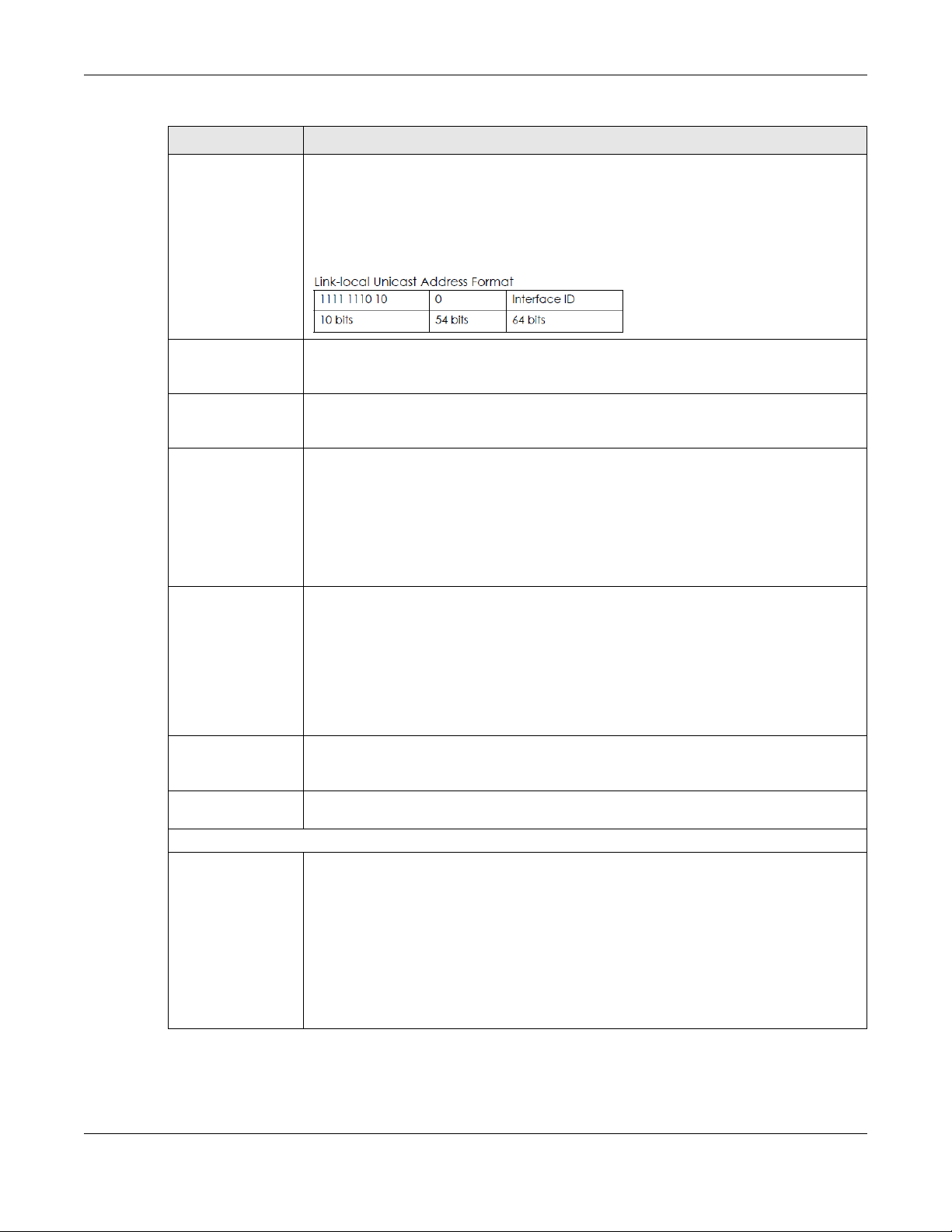
Chapter 7 Home Networking
Table 33 Network Setting > Home Networking > LAN Setup (continued)
LABEL DESCRIPTION
Link Local Address
Type
A link-local address uniquely identifies a device on the local network (the LAN). It is similar to
a “private IP address” in IPv6. You can have the same link-local address on multiple
interfaces on a device. A link-local unicast address has a predefined prefix of fe80::/10. The
link-local unicast address format is as follows. Select EU
generate an interface ID for the LAN interface’s link-local address using the EU
Otherwise, enter an interface ID for the LAN interface’s link-local address if you select
Manual.
I64 to allow the Zyxel Device to
I-64 format.
LAN Global
Identifier Type
LAN IPv6 Prefix
Setup
LAN IPv6 Address
Assign Setup
LAN IPv6 DNS Assign
Setup
DHCPv6
Configuration
IPv6 Router
Advertisement State
IPv6 DNS Values
IPv6 DNS Server
1~3
Select EU
global address. Select Manual to manually enter an interface ID for the LAN interface’s
global IPv6 address.
Select Delegate prefix from WAN to automatically obtain an IPv6 network prefix from the
service provider or an uplink router. Select Static to configure a fixed IPv6 address for the
Zyxel Device’s LAN IPv6 address.
Select how you want to obtain an IPv6 address:
Stateless: The Zyxel Device uses IPv6 stateless autoconfiguration. RADVD (Router
Advertisement Daemon) is enabled to have the Zyxel Device send IPv6 prefix information in
router advertisements periodically and in response to router solicitations. DHCPv6 server is
disabled.
Stateful: The Zyxel Device uses IPv6 stateful autoconfiguration. The DHCPv6 server is enabled
to have the Zyxel Device act as a DHCPv6 server and pass IPv6 addresses to DHCPv6 clients.
Select how the Zyxel Device provide DNS server and domain name information to the
clients:
From Router Advertisement: The Zyxel Device provides DNS information through router
advertisements.
From DHCPv6 Server: The Zyxel Device provides DNS information through DHCPv6.
From RA & DHCPv6 Server: The Zyxel Device provides DNS information through both router
advertisements and DHCPv6.
DHCPv6 Active shows the status of the DHCPv6. DHCPv6 Server displays if you configured the
Zyxel Device to act as a DHCPv6 server which assigns IPv6 addresses and/or DNS information
to clients.
RADVD Active shows whether RADVD is enabled or not.
Specify the IP addresses up to three DNS servers for the DHCP clients to use. Use one of the
following ways to specify these IP addresses.
User Defined - Select this if you have the IPv6 address of a DNS server. Enter the DNS server
IPv6 addresses the Zyxel Device passes to the DHCP clients.
From ISP - Select this if your ISP dynamically assigns IPv6 DNS server information.
Proxy - Select this if the DHCP clients use the IP address of this interface and the Zyxel Device
works as a DNS relay.
Otherwise, select None if you do not want to configure IPv6 DNS servers.
I64 to have the Zyxel Device generate an interface ID using the EUI-64 format for its
LTE Series User’s Guide
92
Page 93

Table 33 Network Setting > Home Networking > LAN Setup (continued)
LABEL DESCRIPTION
DNS Query Scenario Select how the Zyxel Device handles clients’ DNS information requests.
Apply Click Apply to save your changes.
Cancel Click Cancel to restore your previously saved settings.
7.3 Static DHCP
Chapter 7 Home Networking
IPv4/IPv6 DNS Server: The Zyxel Device forwards the requests to both the IPv4 and IPv6 DNS
servers and sends clients the first DNS information it receives.
IPv6 DNS Server Only: The Zyxel Device forwards the requests to the IPv6 DNS server and
sends clients the DNS information it receives.
IPv4 DNS Server Only: The Zyxel Device forwards the requests to the IPv4 DNS server and
sends clients the DNS information it receives.
IPv6 DNS Server First: The Zyxel Device forwards the requests to the IPv6 DNS server first and
then the IPv4 DNS server. Then it sends clients the first DNS information it receives.
IPv4 DNS Server First: The Zyxel Device forwards the requests to the IPv4 DNS server first and
then the IPv6 DNS server. Then it sends clients the first DNS information it receives.
When any of the LAN clients in your network want an assigned fixed IP address, add a static lease for
each LAN client. Knowing the LAN client’s MAC addresses is necessary. Assign IP addresses on the LAN
to specific individual computers based on their MAC addresses.
Every Ethernet device has a unique MAC (Media Access Control) address. The MAC address is assigned
at the factory and consists of six pairs of hexadecimal characters, for example, 00:A0:C5:00:00:02.
7.3.1 Before You Begin
Find out the MAC addresses of your network devices if you intend to add them to the Static DHCP
screen.
Use this screen to change your Zyxel Device’s static DHCP settings. Click Network Setting > Home
Networking > Static DHCP to open the following screen.
Figure 62 Network Setting > Home Networking > Static DHCP
LTE Series User’s Guide
93
Page 94

Chapter 7 Home Networking
The following table describes the labels in this screen.
Table 34 Network Setting > Home Networking > Static DHCP
LABEL DESCRIPTION
Static DHCP
Configuration
# This is the index number of the entry.
Status Active
MAC Address The MAC (Media Access Control) or Ethernet address on a LAN (Local Area Network) is
IP Address This field displays the IP address relative to the # field listed above.
Modify Click the Edit icon to configure the connection.
Click this to configure a static DHCP entry.
unique to your computer (six pairs of hexadecimal notation).
A network interface card such as an Ethernet adapter has a hardwired address that is
assigned at the factory. This address follows an industry standard that ensures no other
adapter has a similar address.
If you click Static DHCP Configuration in the Static DHCP screen, the following screen displays.
Figure 63 Static DHCP: Static DHCP Configuration
The following table describes the labels in this screen.
Table 35 Static DHCP: Configuration
LABEL DESCRIPTION
Active Enable static DHCP in your Zyxel Device.
Group Name This displays the Group Name, usually Default.
IP Type The IP Type is normally IPv4 (non-configurable).
Select Device Info Select between Manual Input which allows you to enter the next two fields (MAC Address
and IP Address); or selecting an existing device would show its MAC address and IP address.
MAC Address Enter the MAC address of a computer on your LAN if you select Manual Input in the previous
field.
IP Address Enter the IP address that you want to assign to the computer on your LAN with the MAC
OK Click OK to save your changes.
Cancel Click Cancel to exit this screen without saving.
address that you will also specify if you select Manual Input in the previous field.
LTE Series User’s Guide
94
Page 95

7.4 UPnP
Universal Plug and Play (UPnP) is a distributed, open networking standard that uses TCP/IP for simple
peer-to-peer network connectivity between networking devices and software that also have UPnP
enabled. A UPnP device can dynamically join a network, obtain an IP address, convey its capabilities
and learn about other devices on the network. A device can leave a network smoothly and
automatically when it is no longer in use.
See Section 7.6 on page 97 for more information on UPnP.
Use the following screen to configure the UPnP settings on your Zyxel Device. Click Network Setting >
Home Networking > UPnP to display the screen shown next.
Figure 64 Network Setting > Home Networking > UPnP
Chapter 7 Home Networking
The following table describes the labels in this screen.
Table 36 Network Settings > Home Networking > UPnP
LABEL DESCRIPTION
UPnP State
UPnP Select Enable to activate UPnP. Be aware that anyone could use a UPnP application to open
UPnP NAT-T State
UPnP NAT-T Select Enable to activate UPnP with NAT enabled. UPnP NAT traversal automates the process
# This field displays the index number of the entry.
Description This field displays the description of the UPnP NAT-T connection.
Destination IP
Address
External Port This field displays the external port number that identifies the service.
the Web Configurator's login screen without entering the Zyxel Device's IP address (although
you must still enter the password to access the Web Configurator).
of allowing an application to operate through NAT. UPnP network devices can automatically
configure network addressing, announce their presence in the network to other UPnP devices
and enable exchange of simple product and service descriptions.
This field displays the IP address of the other connected UPnP-enabled device.
LTE Series User’s Guide
95
Page 96

Chapter 7 Home Networking
Table 36 Network Settings > Home Networking > UPnP
LABEL DESCRIPTION
Internal Port This field displays the internal port number that identifies the service.
Protocol This field displays the protocol of the NAT mapping rule (TCP or UDP).
Apply Click Apply to save your changes.
Cancel Click Cancel to restore your previously saved settings.
7.5 Technical Reference
This section provides some technical background information about the topics covered in this chapter.
LANs, WANs and the Zyxel Device
The actual physical connection determines whether the Zyxel Device ports are LAN or WAN ports. There
are two separate IP networks, one inside the LAN network and the other outside the WAN network as
shown next.
Figure 65 LAN and WAN IP Addresses
Private IP Addresses
Every machine on the Internet must have a unique address. If your networks are isolated from the
Internet, for example, only between your two branch offices, you can assign any IP addresses to the
hosts without problems. However, the Internet Assigned Numbers Authority (IANA) has reserved the
following three blocks of IP addresses specifically for private networks:
• 10.0.0.0 — 10.255.255.255
• 172.16.0.0 — 172.31.255.255
• 192.168.0.0 — 192.168.255.255
You can obtain your IP address from the IANA, from an ISP or it can be assigned from a private network.
If you belong to a small organization and your Internet access is through an ISP, the ISP can provide you
LTE Series User’s Guide
96
Page 97
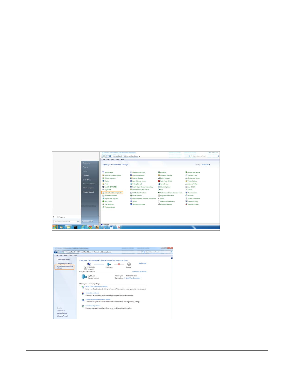
Chapter 7 Home Networking
with the Internet addresses for your local networks. On the other hand, if you are part of a much larger
organization, you should consult your network administrator for the appropriate IP addresses.
Note: Regardless of your particular situation, do not create an arbitrary IP address; always
follow the guidelines above. For more information on address assignment, please refer
to RFC 1597, “Address Allocation for Private Internets” and RFC 1466, “Guidelines for
Management of IP Address Space.”
7.6 Turn on UPnP in Windows 7 Example
This section shows you how to use the UPnP feature in Windows 7. UPnP server is installed in Windows 7.
Activate UPnP on the Zyxel Device by clicking Network Setting > Home Networking > UPnP.
Make sure the computer is connected to the LAN port of the Zyxel Device. Turn on your computer and
the Zyxel Device.
1 Click the start icon, Control Panel and then the Network and Sharing Center.
2 Click Change Advanced Sharing Settings.
3 Select Turn on network discovery and click Save Changes. Network discovery allows your computer to
find other computers and devices on the network and other computers on the network to find your
computer. This makes it easier to share files and printers.
LTE Series User’s Guide
97
Page 98

Chapter 7 Home Networking
7.6.1 Auto-discover Your UPnP-enabled Network Device
Before you follow these steps, make sure you already have UPnP activated on the Zyxel Device and in
your computer.
Make sure your computer is connected to the LAN port of the Zyxel Device.
1 Open Windows Explorer and click Network.
2 Right-click the Zyxel Device icon and select Properties.
Figure 66 Network Connections
LTE Series User’s Guide
98
Page 99

Chapter 7 Home Networking
3 In the Internet Connection Properties window, click Settings to see port mappings.
Figure 67 Internet Connection Properties
4 You may edit or delete the port mappings or click Add to manually add port mappings.
Figure 68 Internet Connection Properties: Advanced Settings
LTE Series User’s Guide
99
Page 100

Chapter 7 Home Networking
Figure 69 Internet Connection Properties: Advanced Settings: Add
Note: When the UPnP-enabled device is disconnected from your computer, all port
mappings will be deleted automatically.
5 Click OK. Check the network icon on the system tray to see your Internet connection status.
Figure 70 System Tray Icon
6 To see more details about your current Internet connection status, right click the network icon in the
system tray and click Open Network and Sharing Center. Click Local Area Network.
Figure 71 Internet Connection Status
7.7 Turn on UPnP in Windows 10 Example
This section shows you how to use the UPnP feature in Windows 10. UPnP server is installed in Windows 10.
Activate UPnP on the Zyxel Device by clicking Network Setting > Home Networking > UPnP.
Make sure the computer is connected to the LAN port of the Zyxel Device. Turn on your computer and
the Zyxel Device.
LTE Series User’s Guide
100
 Loading...