

Page 1
Default Login Details
User’s Guide
LTE2566-M634
4G LTE-A Portable Router
LAN IP Address http: //192.168.1.1
Username admin
Password 1234
Version 1.0 Edition 1, 1/2020
Copyright © 2020 Zyxel Communications Corporation
Page 2

IMPORTANT!
READ CAREFULLY BEFORE USE.
KEEP THIS GUIDE FOR FUTURE REFERENCE.
Screenshots and graphics in this book may differ slightly from your product due to differences in your
product firmware. Every effort has been made to ensure that the information in this manual is accurate.
Related Documentation
•Quick Start Guide
The Quick Start Guide shows how to connect and install the LTE2566-M634.
•More Information
Go to support.zyxel.com to find other information on the LTE2566-M634
.
LTE2566-M634 User’s Guide
2
Page 3

Contents Overview
Contents Overview
Get to Know Your
LTE2566-M634 .................................................................................................................................. 11
User’s Guide ......................................................................................................................................23
Web Configurator ................................................................................................................................. 24
Setup Wizard ......................................................................................................................................... 30
Tutorials .................................................................................................................................................. 34
Technical Reference ........................................................................................................................40
Status ...................................................................................................................................................... 41
Monitor ................................................................................................................................................... 44
WAN ....................................................................................................................................................... 50
WLAN ...................................................................................................................................................... 58
LAN ......................................................................................................................................................... 72
NAT ......................................................................................................................................................... 74
DHCP Server .......................................................................................................................................... 82
DDNS ...................................................................................................................................................... 86
Firewall ................................................................................................................................................... 88
URL Filtering ............................................................................................................................................ 92
IPv4 Filter ................................................................................................................................................ 94
SMS ......................................................................................................................................................... 96
MGMT Interface .................................................................................................................................. 103
Universal Plug-and-Play (UPnP) ......................................................................................................... 106
TR-069 ................................................................................................................................................... 121
Maintenance ...................................................................................................................................... 123
Troubleshooting .................................................................................................................................. 132
LTE2566-M634 User’s Guide
3
Page 4

Table of Contents
Table of Contents
Contents Overview..............................................................................................................................3
Table of Contents.................................................................................................................................4
Document Conventions ... .... ............................................ .... ... ............................................. ... ..........10
Chapter 1
Get to Know Your LTE2566-M634 ......................................................................................................11
1.1 Overview ......................................................................................................................................... 11
1.2 Applications .................................................................................................................................... 11
1.3 Ways to Manage the LTE2566-M634 ............................................................................................12
1.4 Hardware Description .................................................................................................................... 12
1.4.1 Power Button ......................................................................................................................... 14
1.4.2 Hardware Connections ........................................................................................................ 14
1.4.3 Reset the LTE2566-M634 ........................................................................................................ 15
1.5 LCD Screens .................................................................................................................................... 15
1.5.1 LCD Menu Screen ................................................................................................................. 16
1.5.2 Network Connection ............................................................................................................ 17
1.5.3 Data Usage ............................................................................................................................ 17
1.5.4 WiFi Setting ............................................................................................................................. 18
1.5.5 SSID & Password Setting ....................................................................................................... 19
1.5.6 WPS ......................................................................................................................................... 19
1.5.7 Viewing SMS ........................................................................................................................... 20
1.5.8 About Screen ........................................................................................................................ 21
Chapter 2
Web Configurator...............................................................................................................................24
2.1 Introduction ..................................................................................................................................... 24
2.2 Accessing the Web Configurator ................................................................................................. 24
2.3 Navigating the Web Configurator ............................................................................................... 25
2.3.1 Title Bar ................................................................................................................................... 26
2.3.2 The Main Window ................................................................................................................. 27
2.3.3 Navigation Panel: Main Menus ........................................................................................... 27
2.3.4 Navigation Panel: Sub-Menus ............................................................................................. 27
Chapter 3
Setup Wizard.......................................................................................................................................30
3.1 Overview ......................................................................................................................................... 30
3.2 Accessing the Wizard ..................................................................................................................... 30
3.3 Wizard Setup ................................................................................................................................... 30
LTE2566-M634 User’s Guide
4
Page 5

Table of Contents
Chapter 4
Tutorials...............................................................................................................................................34
4.1 Overview ......................................................................................................................................... 34
4.2 Set Up Your WiFi Network ............................................................................................................... 34
4.3 Connect to the LTE2566-M634 WiFi Network ............................................................................... 35
4.4 Set Up a Wireless Network Using WPS ........................................................................................... 37
4.5 Configure Data Usage and Statistics ........................................................................................... 38
Chapter 5
Status...................................................................................................................................................41
5.1 Overview ......................................................................................................................................... 41
5.2 Status ................................................................................................................................................ 41
Chapter 6
Monitor................................................................................................................................................44
6.1 Overview ......................................................................................................................................... 44
6.1.1 What You Can Do in this Chapter ....................................................................................... 44
6.2 The Log Screen ............................................................................................................................... 44
6.3 DHCP Table ..................................................................................................................................... 45
6.4 ARP Table ........................................................................................................................................ 46
6.5 Packet Statistics .............................................................................................................................. 47
6.6 LTE Modem Status ........................................................................................................................... 47
Chapter 7
WAN ....................................................................................................................................................50
7.1 Overview ......................................................................................................................................... 50
7.1.1 What You Can Do in this Chapter ....................................................................................... 50
7.1.2 What You Need To Know ..................................................................................................... 51
7.2 WAN Management ........................................................................................................................ 52
7.3 PLMN Selection ............................................................................................................................... 54
7.4 .IPv6 .................................................................................................................................................. 55
7.5 PIN Management ........................................................................................................................... 55
7.6 Data Usage ..................................................................................................................................... 56
Chapter 8
WLAN...................................................................................................................................................58
8.1 Overview ......................................................................................................................................... 58
8.1.1 What You Can Do in this Chapter ....................................................................................... 58
8.1.2 What You Need to Know ..................................................................................................... 59
8.2 The General Screen ....................................................................................................................... 60
8.3 Wireless Security .............................................................................................................................. 63
8.3.1 No Security ............................................................................................................................. 63
8.3.2 WPA2-PSK ............................................................................................................................... 63
LTE2566-M634 User’s Guide
5
Page 6

Table of Contents
8.3.3 WPA-PSK / WPA2-PSK ............................................................................................................ 65
8.4 Guest AP .......................................................................................................................................... 66
8.5 The MAC Filter Screen .................................................................................................................... 67
8.6 Wireless LAN Advanced Settings .................................................................................................. 68
8.7 The WPS SetUp Screen ................................................................................................................... 69
8.8 WPS Station ...................................................................................................................................... 70
Chapter 9
LAN......................................................................................................................................................72
9.1 Overview ......................................................................................................................................... 72
9.1.1 What You Can Do ................................................................................................................. 72
9.1.2 What You Need To Know ..................................................................................................... 72
9.2 LAN IP ............................................................................................................................................... 73
Chapter 10
NAT......................................................................................................................................................74
10.1 Overview ....................................................................................................................................... 74
10.1.1 What You Can Do ............................................................................................................... 74
10.1.2 What You Need to Know ...................................................................................................75
10.2 Port Forwarding ............................................................................................................................. 76
10.3 Port Trigger ..................................................................................................................................... 78
10.4 ALG ................................................................................................................................................. 78
10.5 Technical Reference .................................................................................................................... 79
10.5.1 NAT Port Forwarding: Services and Port Numbers ........................................................... 79
10.5.2 NAT Port Forwarding Example ........................................................................................... 80
10.5.3 Trigger Port Forwarding ...................................................................................................... 80
10.5.4 Trigger Port Forwarding Example ...................................................................................... 80
10.5.5 Two Points To Remember About Trigger Ports ................................................................. 81
Chapter 11
DHCP Server........................................................................................................................................82
11.1 Overview ....................................................................................................................................... 82
11.1.1 What You Can Do ............................................................................................................... 82
11.1.2 What You Need To Know ...................................................................................................82
11.2 DHCP Server General Settings .................................................................................................... 82
11.3 Advanced DHCP Server Setting ................................................................................................. 84
11.4 DHCP Client List ............................................................................................................................. 84
Chapter 12
DDNS ...................................................................................................................................................86
12.1 Overview ....................................................................................................................................... 86
12.2 General Settings ........................................................................................................................... 86
LTE2566-M634 User’s Guide
6
Page 7

Table of Contents
Chapter 13
Firewall................................................................................................................................................88
13.1 Overview ....................................................................................................................................... 88
13.1.1 What You Can Do ............................................................................................................... 88
13.1.2 What You Need To Know ...................................................................................................88
13.2 General Setting ............................................................................................................................. 89
13.3 The ICMP Protection ..................................................................................................................... 90
Chapter 14
URL Filtering.........................................................................................................................................92
14.1 Overview ....................................................................................................................................... 92
14.2 URL Filter ......................................................................................................................................... 92
Chapter 15
IPv4 Filter.............................................................................................................................................94
15.1 Overview ....................................................................................................................................... 94
15.2 IPv4 Firewall ................................................................................................................................... 94
Chapter 16
SMS......................................................................................................................................................96
16.1 Overview ....................................................................................................................................... 96
16.1.1 What You Can Do in this Chapter ..................................................................................... 96
16.2 SMS Summary ................................................................................................................................ 96
16.2.1 Set SMS Storage Location .................................................................................................. 96
16.3 New SMS ........................................................................................................................................ 97
16.4 SMS Inbox List ................................................................................................................................ 98
16.5 SMS Draft Box ................................................................................................................................ 98
16.6 SMS Outbox List ............................................................................................................................. 99
16.7 The USSD Screen ......................................................................................................................... 100
16.8 Phonebook .................................................................................................................................. 101
16.8.1 The Phonebook Screen ....................................................................................................101
16.8.2 The Groups Screen ............................................................................................................ 102
Chapter 17
MGMT Interface ...............................................................................................................................103
17.1 Overview ..................................................................................................................................... 103
17.2 What You Can Do ...................................................................................................................... 103
17.3 What You Need To Know .......................................................................................................... 103
17.3.1 System Timeout .................................................................................................................. 103
17.4 Local MGMT ................................................................................................................................ 103
17.5 Remote MGMT ............................................................................................................................ 104
LTE2566-M634 User’s Guide
7
Page 8

Table of Contents
Chapter 18
Universal Plug-and-Play (UPnP)............................ .... ............................................ .... ... .... ...............106
18.1 Overview ..................................................................................................................................... 106
18.2 What You Need to Know ........................................................................................................... 106
18.2.1 NAT Traversal ..................................................................................................................... 106
18.2.2 Cautions With UPnP ........................................................................................................... 106
18.3 UPnP Settings ............................................................................................................................... 107
18.4 Turn on UPnP in Windows 7 Example ........................................................................................ 107
18.4.1 Auto-discover Your UPnP-enabled Network Device .................................................... 109
18.5 Turn on UPnP in Windows 10 Example ...................................................................................... 111
18.5.1 Auto-discover Your UPnP-enabled Network Device .................................................... 113
18.6 Web Configurator Easy Access in Windows 7 ......................................................................... 116
18.7 Web Configurator Easy Access in Windows 10 ....................................................................... 118
Chapter 19
TR-069................................................................................................................................................121
19.1 Overview ..................................................................................................................................... 121
19.2 TR-069 Settings ............................................................................................................................. 121
Chapter 20
Maintenance....................................................................................................................................123
20.1 Overview ..................................................................................................................................... 123
20.1.1 What You Can Do in this Chapter ................................................................................... 123
20.2 The General Screen ................................................................................................................... 123
20.3 The User Account Screen .......................................................................................................... 124
20.4 The Time Screen .......................................................................................................................... 125
20.5 The Power Saving Screen .......................................................................................................... 127
20.6 The LCD Display Screen ............................................................................................................. 128
20.7 The Firmware Upgrade Screen ................................................................................................. 129
20.8 Configuration Backup/Restore ................................................................................................. 129
20.9 The Reboot Screen ..................................................................................................................... 131
20.10 The Reset Screen ...................................................................................................................... 131
Chapter 21
Troubleshooting................................................................................................................................132
21.1 Overview ..................................................................................................................................... 132
21.2 Power ........................................................................................................................................... 132
21.3 LTE2566-M634 Access and Login .............................................................................................. 132
21.4 Internet Access ........................................................................................................................... 134
21.5 IP Address Setup ......................................................................................................................... 135
21.6 WiFi Connections ........................................................................................................................ 138
21.7 Getting More Troubleshooting Help .........................................................................................138
LTE2566-M634 User’s Guide
8
Page 9

Table of Contents
Appendix A Customer Support ..................................................................................................... 139
Appendix B Legal Information....................................................................................................... 145
LTE2566-M634 User’s Guide
9
Page 10

Document Conventions
Document Conventions
Warnings and Notes
These are how warnings and notes are shown in this guide.
Warnings tell you about things that could harm you or your device.
Note: Notes tell you other important information (for example, other things you may need to
configure or helpful tips) or recommendations.
Syntax Conventions
• Product labels, screen names, field labels and field choices are all in bold font.
• A right angle bracket ( > ) within a screen name denotes a mouse click. For example, Configuration >
Network > NAT > Port Trigger means you first click Configuration in the navigation panel, then Network,
then the NAT sub menu and finally the Port Trigger tab to get to that screen.
Icons Used in Figures
Figures in this user guide may use the following generic icons. The LTE2566-M634 icon is not an exact
representation of your device.
LTE2566-M634 Generic Router Switch
Server Firewall Smartphone
Tablet Antenna Tower Home
Outdoors Printer
LTE2566-M634 User’s Guide
10
Page 11

1.1 Overview
A
Your LTE2566-M634 (A) is a 4G LTE router that allows you to share Internet Access via WiFi anytime. The
LTE2566-M634 supports 4G/3G multi-mode and complies with the IEEE 802.11a/b/g/n/ac standards. It
can provide data rates of up to 300Mbps to up to 32 simultaneous WiFi clients. The LTE2566-M634’s slim
design is easy to use anywhere anytime and leaves your smartphone’s bandwidth and battery free for
other purposes.
CHAPTER 1
Get to Know Your
LTE2566-M634
1.2 Applications
You can have the following networks with the LTE2566-M634:
• Wireless LAN (WiFi): Wireless clients can connect to the LTE2566-M634 using the network’s SSID and
Password. For WPS-compatible devices you can create an instant network connection using WPS
(WiFi Protected Security).
• WAN: Connect to a mobile network for Internet access.
LTE2566-M634 User’s Guide
11
Page 12

Chapter 1 Get to Know Your LTE2566-M634
LCD Screen
Center Button
Right Button
Left Button
1.3 Ways to Manage the LTE2566-M634
• Navigation Buttons
You can use the navigation buttons along with the LCD interface to manage the LTE2566-M634.
• Web Configurator
The Web Configurator is recommended for everyday management by using a supported web browser.
1.4 Hardware Description
The following images show the front and side panels of the LTE2566-M634.
Figure 1 Front Panel
You can use the center, right, and left buttons to navigate the LCD screen.
• Press the center button to select the Menu button on the LCD and go to the Menu screen.
LTE2566-M634 User’s Guide
12
Page 13

Chapter 1 Get to Know Your LTE2566-M634
USB Port
Figure 2 Menu Button
• The Menu screen appears. Press the left or right button to scroll up and down and then press the
center button to select an option.
Figure 3 Menu Screen
Figure 4 Left Panel
LTE2566-M634 User’s Guide
13
Page 14

Figure 5 Right Panel
Power Button
Reset Button
Micro SIM Card Slot
Chapter 1 Get to Know Your LTE2566-M634
1.4.1 Power Button
Use the power button on the side panel to turn the LTE2566-M634 on or off. To turn on, press the power
button for 3 seconds until the LCD screen displays ZYXEL.
Power Off
To turn the LTE2566-M634 off, press the power button once to wake up the LCD, then press for 3 seconds
and release it when the LCD screen displays Shut down.
1.4.2 Hardware Connections
See your Quick Start Guide for more information about hardware installation.
LTE2566-M634 User’s Guide
14
Page 15

Chapter 1 Get to Know Your LTE2566-M634
1.4.3 Reset the LTE2566-M634
Remove the SIM card cover. Use a SIM ejector pin or a paper clip to press the reset button and release
it when the LCD screen displays Reset.
This resets the LTE2566-M634 to the factory default configuration. This means that you will lose all
configurations that you had previously, such as WiFi SSID and password.
1.5 LCD Screens
This section describes the labels or icons displayed on the LCD screen of your LTE2566-M634. When the
LTE2566-M634 first turns on the following example screen displays.
Figure 6 LCD Home Screen
The following table describes the labels in this screen.
Table 1 LTE2566-M634’s LCD Home Screen
LABEL DESCRIPTION
This displays the type of network your LTE2566-M634 is connected to and its signal
strength. Your network can be either 3G or 4G.
This displays if the SIM card could not be detected by the LTE2566-M634.
This displays if the SIM card’s data plan cannot be used in another country.
This displays when the LTE2566-M634 cannot access the SIM card because it is
locked.
This displays when the LTE2566-M634 is receiving/transmitting data to/from the
Internet.
This displays the
currently connected to the LTE2566-M634.
LTE2566-M634 User’s Guide
WiFi network status. The number indicates how many clients are
15
Page 16
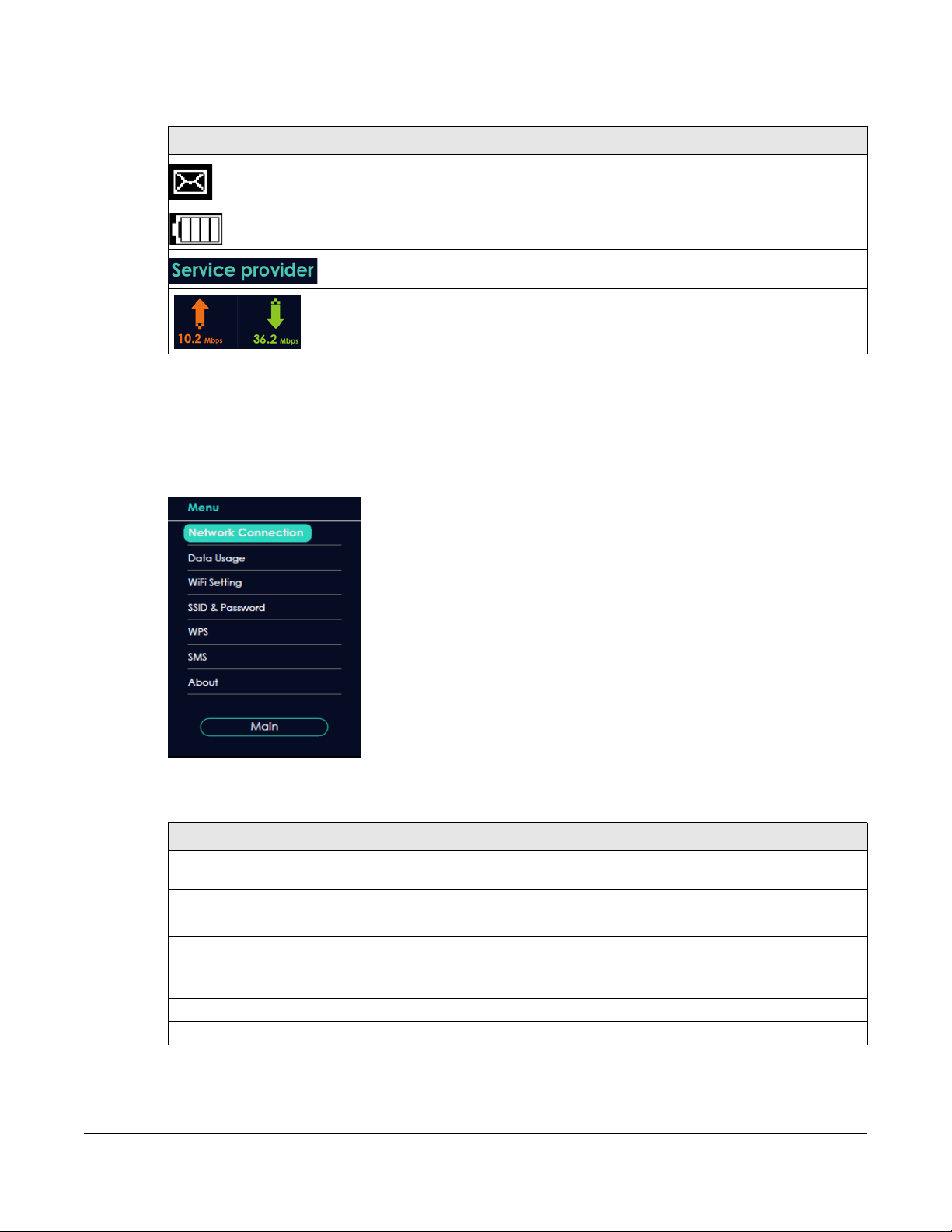
Table 1 LTE2566-M634’s LCD Home Screen (continued)
LABEL DESCRIPTION
1.5.1 LCD Menu Screen
Press the center button to select the Menu button on the LCD. The LCD Menu screen appears. Press the
left or right button to scroll up and down and then press the center button to select an option.
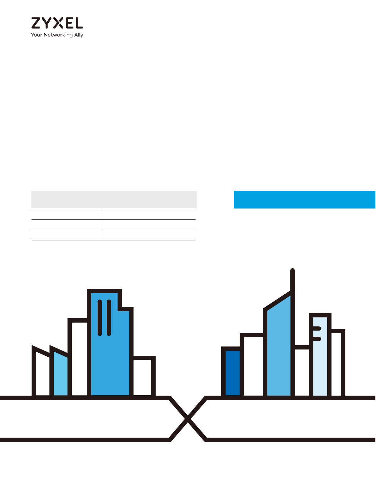
Figure 7
Chapter 1 Get to Know Your LTE2566-M634
This displays when the LTE2566-M634 receives an SMS (Short Message Service)
message.
This icon shows the LTE2566-M634 battery life.
This shows your LTE2566-M634’s Internet Service Provider.
This displays the LTE2566-M634’s speed when receiving/transmitting data to/from the
Internet.
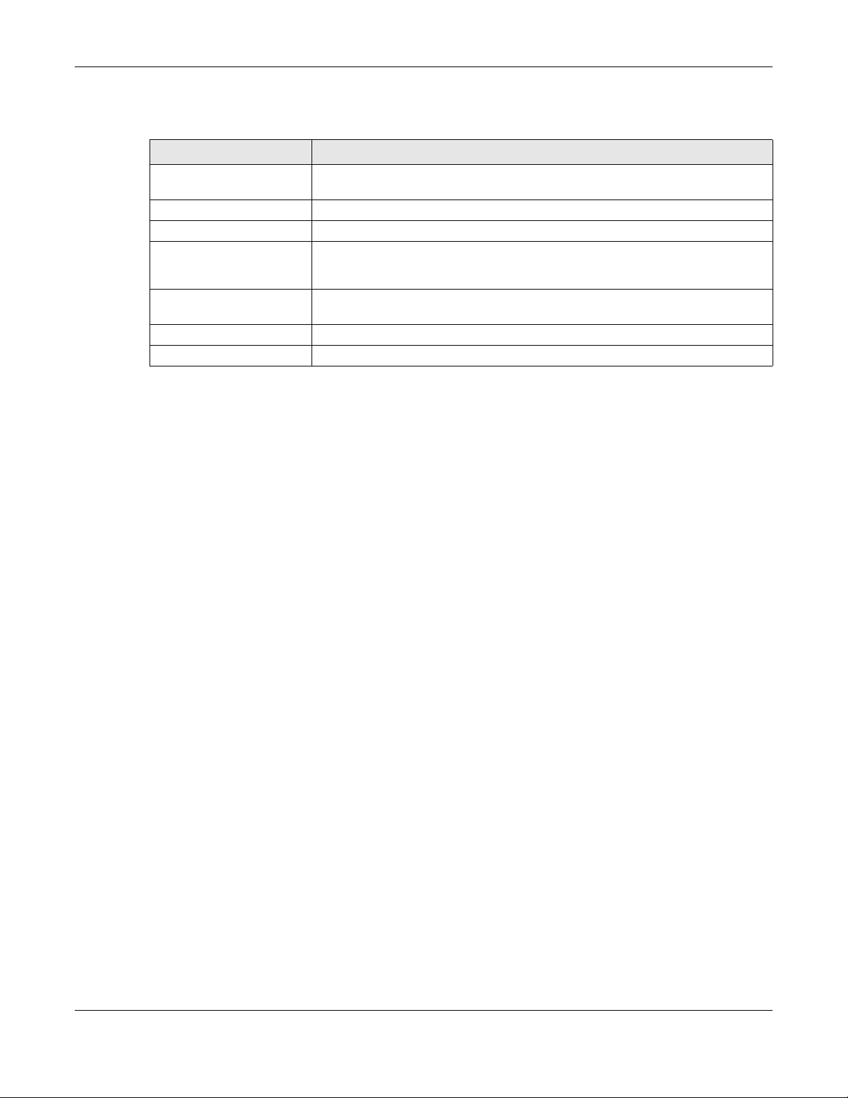
The following table describes the labels in the Menu screen.
Table 2 LCD Menu Screen
LABEL DESCRIPTION
Network Connection Use Network Connection to see your network status and to connect to a 3G/4G
network.
Data Usage Use Data Usage to activate data control on the LTE2566-M634.
WiFi Setting Use WiFi Setting to enable 2.4GHz / 5GHz WiFi.
SSID & Password Use SSID & Password to allow a client device to find this SSID and enter the Password
to connect wirelessly to the LTE2566-M634.
WPS If your client supports WPS, use WPS to connect wirelessly to the LTE2566-M634.
SMS Use SMS to check SMS messages.
About Use About to see the LTE2566-M634 hardware/firmware information.
LTE2566-M634 User’s Guide
16
Page 17
Chapter 1 Get to Know Your LTE2566-M634
1.5.2 Network Connection
To show the network status and connect to the network service, press the left or right button to navigate
to Network Connection and the center button to select it.
Figure 8 Network Connection Screen
The following table describes the labels in this screen.
Table 3 Network Connection Screen
LABEL DESCRIPTION
Status This displays the network status of the LTE2566-M634.
Operator This displays the service provider’s name of your 3G/4G network (WAN).
Mode This displays the current mode of your LTE2566-M634 (4G or 3G).
Wan IP This displays the current IP address of the LTE2566-M634 in the WAN.
DNS IP This displays the DNS server address assigned to the LTE2566-M634.
Connect/Disconnect Click this button to enable/disable WAN network services.
Menu Click this button to return to the Menu list.
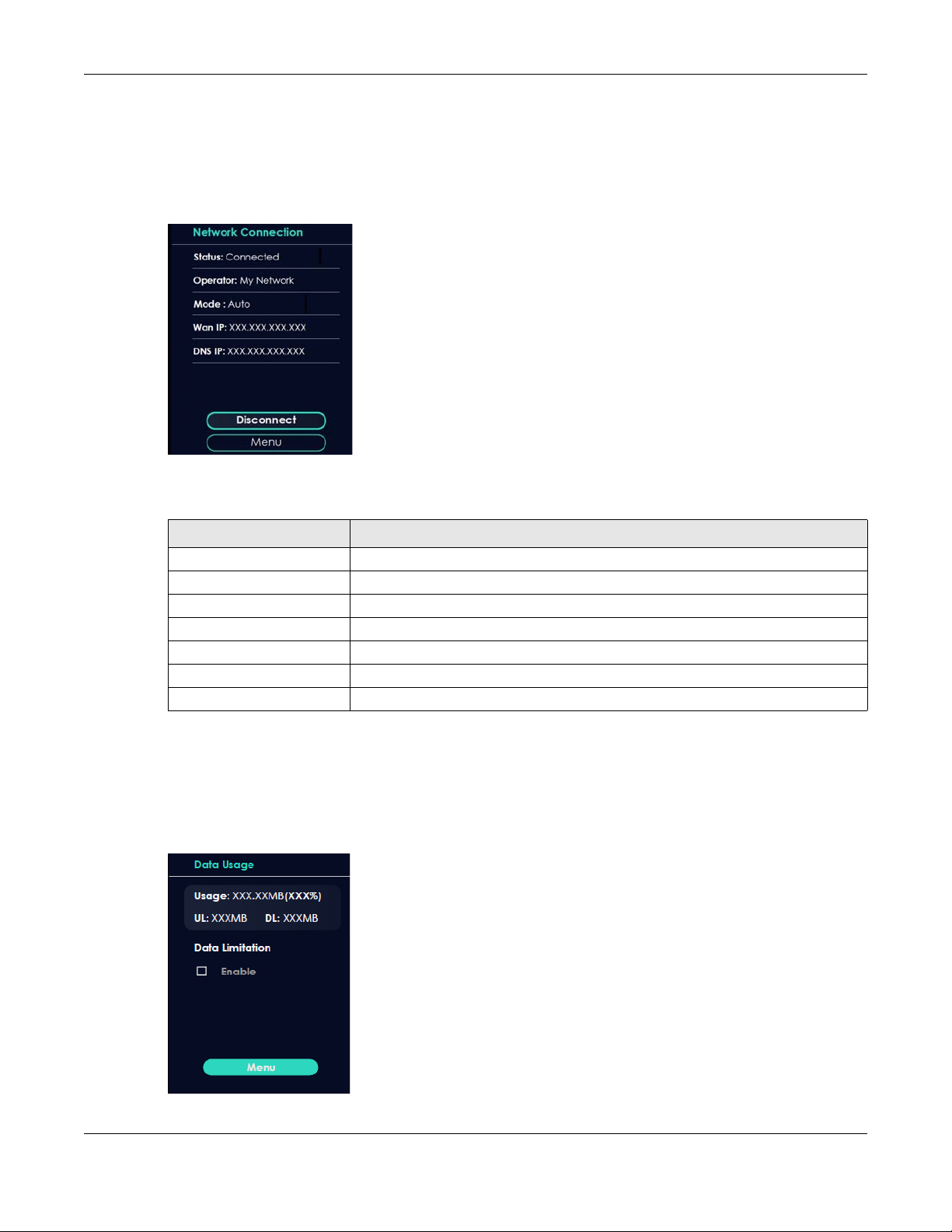
1.5.3 Data Usage
To show the amount of data usage on the WAN, press the left or right button to go to Data Usage and
the center button to select it. The following screen displays.
Figure 9 Data Usage Screen
LTE2566-M634 User’s Guide
17
Page 18

Chapter 1 Get to Know Your LTE2566-M634
The following table describes the labels in this screen.
Table 4 Data Usage Screen
LABEL DESCRIPTION
Usage This displays the mobile data used in total by your LTE2566-M634 in Kilobytes (KB),
UL This displays the amount of data in KB/MB/GB currently uploaded by the LTE2566-
DL This displays the amount of data in KB/MB/GB currently downloaded by the LTE2566-
Data Limitation Use the Web Configurator to set a data cap which prevents you from using a certain
Menu Click this button to return to the Menu list.
Megabytes (MB), or Gigabytes (GB).
M634.
M634.
amount of data.
Click to Enable notification on the LCD when 80% and 100% of data usage is
reached. For example, you can set the limit at 100 MB. The LCD will display Data
Usage Reach 80% Limit when 80% of data usage is reached. Once you reach that
limit, the LCD will display ! Data Usage Reach 100% Limit and your cellular data will
turn off.
To continue using data after the limit is reached, click Enable to disable data
limitation.
Note: You can only use Web Configurator to select the date of the month on which the
LTE2566-M634 restarts calculating the amount of data used every month. See Section
7.6 on page 56 for more information.
1.5.4 WiFi Setting
To enable the WiFi clients (up to 32) to connect to the 2.4GHz / 5GHz WiFi band, press the left or right
button to go to WiFi Setting and the center button to select it. The following screen displays.
Figure 10 WiFi Setting Screen
LTE2566-M634 User’s Guide
18
Page 19

Chapter 1 Get to Know Your LTE2566-M634
The following table describes the labels in this screen.
Table 5 WiFi Setting Screen
LABEL DESCRIPTION
2.4GHz WiFi Click 2.4GHz WiFi to enable WiFi clients to connect to the 2.4GHz WiFi band.
5GHz WiFi Click 5GHz WiFi to enable WiFi clients to connect to the 5GHz WiFi band.
Menu Click this button to return to the Menu list.
1.5.5 SSID & Password Setting
To find the SSID and Password to enable WiFi clients to connect wirelessly to the LTE2566-M634:
1 Press the navigation buttons to go to SSID & Password.
2 Press the center button to show 2.4GHz Wi-Fi SSID and Password.
3 Press the center button to show 5GHz Wi-Fi SSID and Password.
The following screens display. From another device, find this SSID and enter the Password to connect
wirelessly to the LTE2566-M634. Alternatively, use the QR code to scan the SSID and Password.
Figure 11 2.4GHz/5GHz Wi-Fi SSID & Password Screens
1.5.6 WPS
Your LTE2566-M634 supports WiFi Protected Setup (WPS), which is an easy way to set up a secure WiFi
network. WPS is an industry standard specification, defined by the WiFi Alliance.
WPS allows you to quickly set up a WiFi network with strong security, without having to configure security
settings manually. Each WPS connection works between two devices. Both devices must support WPS
(check each device’s documentation to make sure). When WPS is activated on a device, it has two
minutes to find another device that also has WPS activated. Then, the two devices connect and set up
a secure network by themselves.
You can use the LCD of the LTE2566-M634 to activate WPS in order to quickly set up a WiFi network with
strong security.
1 Press the power button to turn on the LCD.
LTE2566-M634 User’s Guide
19
Page 20

Chapter 1 Get to Know Your LTE2566-M634
2 Press the center button that corresponds to the Menu button on the LCD.
3 Press the left or right button to select WPS and then press the center button.
Figure 12 WPS Screen
Figure 13 2.4GHz / 5GHz WPS
4 Use the left or right button to choose 2.4GHz WPS or 5GHz WPS and then press the center button to select
it. The 120-second counter starts.
5 Press the WPS button on another WPS-enabled device within range of the LTE2566-M634.
Note: You must activate WPS on the LTE2566-M634 and on another device within 2 minutes of
each other.
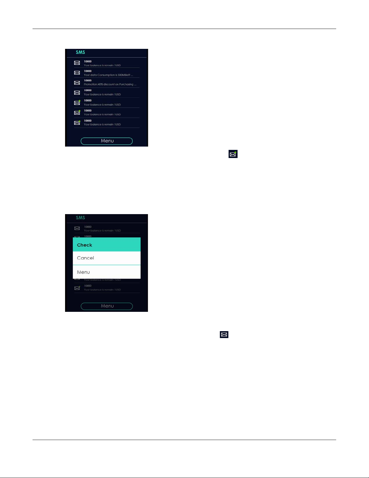
1.5.7 Viewing SMS
SMS (Short Message Service) allows you to view the text messages that the LTE2566-M634 received from
mobile devices or the service provider.
When the SMS box is full the LTE2566-M634 will begin to store text messages in the SIM card. When the SIM
card is full, the LTE2566-M634 will stop storing new SMS messages.
Press the left or right button to go to SMS and the center button to select it. The following screen displays.
LTE2566-M634 User’s Guide
20
Page 21
Chapter 1 Get to Know Your LTE2566-M634
Figure 14 SMS Screen
Use the left, right, and center buttons to select an unread SMS .
1 Use the center button to select Check and view the SMS content.
2 Select Cancel to return to the SMS list.
3 Select Menu to return to the Menu list.
Figure 15 Select an SMS
After reading an SMS message, press the center button to return to the SMS list.
Note: It is highly recommended to delete a read SMS to prevent the SMS box from getting
full. You can only delete SMS messages using the Web Configurator.
1.5.8 About Screen
To show the LTE2566-M634’s hardware/firmware information, press the left or right button to go to About
and the center button to select it.
LTE2566-M634 User’s Guide
21
Page 22
Chapter 1 Get to Know Your LTE2566-M634
The following table describes the labels in this screen.
Table 6 About Screen
LABEL DESCRIPTION
Web This displays http://192.168.1.1. Launch your web browser and go to http://
Firmware This displays the present firmware version of your LTE2566-M634.
SN This displays the serial number issued by the manufacturer for your LTE2566-M634.
IMEI This displays the International Mobile Equipment Number (IMEI) which is the serial
IMSI This displays the International Mobile Subscriber Identity (IMSI) of the installed SIM
MAC This displays the MAC address of the LTE2566-M634.
Main Click this button to return to the Menu list.
192.168.1.1 to access the Web Configurator.
number of the built-in 3G/4G module. IMEI is a unique 15-digit number used to
identify a mobile device.
card. An IMSI is a unique ID used to identify a mobile subscriber in a mobile network.
Note: The LCD screen turns off after 45 seconds if it is idle. Press the power button once to turn
the LCD screen on again.
LTE2566-M634 User’s Guide
22
Page 23

PART I
User’s Guide
23
Page 24

Web Configurator
2.1 Introduction
The Web Configurator is an HTML-based management interface that allows easy LTE2566-M634 setup
and management via Internet browser. Use a browser that supports HTML5, such as an Internet Explorer
11, Mozilla Firefox, or Google Chrome. The recommended screen resolution is 1920 by 1080 pixels.
In order to use the Web Configurator you need to allow:
• JavaScript (enabled by default).
2.2 Accessing the Web Configurator
CHAPTER 2
1 Use the included USB cable to connect your LTE2566-M634 to a computer (refer to the Quick Start
Guide).
2 Make sure your computer has an IP address in the same subnet as the LTE2566-M634. Your computer
should have an IP address from 192.168.1.2 to 192.168.1.254. See your computer help or refer to Section
21.5 on page 135.
3 Launch your web browser. Go to http://192.168.1.1.
4 A login screen displays. To access the administrative Web Configurator and manage the LTE2566-M634,
type the default username admin and password 1234 in the login screen and click Login. If you have
changed the password, enter your password and click Login.
5 The following screen displays if you have not changed your password yet. Enter a new password, retype
it to confirm, and click OK.
LTE2566-M634 User’s Guide
24
Page 25

Chapter 2 Web Configurator
6 After changing your password you are automatically logged out. Log in again with your new password.
The Status screen appears. Use this screen to view your device’s information and status, your mobile
connection status and Internet traffic details.
2.3 Navigating the Web Configurator
The following section summarizes how to navigate the Web Configurator starting from the Status screen.
LTE2566-M634 User’s Guide
25
Page 26

Chapter 2 Web Configurator
A
B
D
C
Figure 16 The Web Configurator’s Main Screen
• A - Title Bar
• B - Navigation Panel: Main Menus
• C - Navigation Panel: Sub-Menus
• D - Main Window
2.3.1 Title Bar
The title bar provides some useful links that always appear over the screens below, regardless of how
deep into the Web Configurator you navigate.
Figure 17 Title Bar
The icons provide the following functions.
Table 7 Title Bar: Web Configurator Icons
LABEL DESCRIPTION
SIM This shows whether a SIM card is inserted in the LTE2566-M634.
Connected Devices This displays the number of devices currently connected to the LTE2566-M634.
WiFi This shows whether the LTE2566-M634’s WiFi network is active.
Signal Strength This shows the current signal strength to the mobile network.
The icon shows if there is no SIM card inserted.
This displays when the LTE2566-M634 is receiving/transmitting data to/from the Internet.
The icon is grayed out if the mobile data connection is not up.
LTE2566-M634 User’s Guide
26
Page 27

Chapter 2 Web Configurator
Table 7 Title Bar: Web Configurator Icons (continued)
LABEL DESCRIPTION
Roaming This shows an R when the LTE2566-M634 is connected to another service provider’s mobile
network using roaming.
Battery The icon shows the battery status.
Language Choose your language from the drop-down list on the upper right corner of the title bar.
2.3.2 The Main Window
The main window displays information and configuration fields. It is discussed in the rest of this
document.
After you log in the Status screen is displayed. See Chapter 5 on page 41 for more information about the
Status screen.
2.3.3 Navigation Panel: Main Menus
Use the menu items in the navigation panel: main menus to open screens to configure LTE2566-M634
features.
Figure 18 Navigation Panel: Main Menus
2.3.4 Navigation Panel: Sub-Menus
Use plus and minus signs to expand and collapse the sub-menus in the navigation panel: sub-menus.
The following sections introduce the LTE2566-M634’s navigation panel menus and their screens.
Figure 19 Navigation Panel: Sub-Menus
LTE2566-M634 User’s Guide
27
Page 28

Chapter 2 Web Configurator
The following table describe each menu item and icons.
Table 8 Navigation Panel Summary
LINK TAB DESCRIPTION
Status Use this screen to view the network status of the LTE2566-M634 and
Monitor
Log View Log Use this screen to view the LTE2566-M634 system logs.
DHCP Table DHCP Table Use this screen to obtain an IP address for a device in the LTE2566-
ARP Table ARP Table Use this screen to view the IP-to-MAC address mappings. It also shows
Packet Statistics Packet Statistics Use this screen to view port status and packet specific statistics.
LTE Modem LTE Modem Status Use this screen to view information on your ISP, and your SIM status.
Configuration
Network
WAN WAN Management This screen allows you to configure ISP parameters, WAN IP address
PLMN Selection Use this screen to view available Public Land Mobile Networks (PLMNs)
IPv6 Use this screen to configure the LTE2566-M634’s IPv6 settings.
PIN Management Use this screen to enable PIN code authentication and enter the PIN
DATA Usage Specify limiting the amount of the package data and view the LTE2566-
Wireless LAN General Use this screen to enable the wireless LAN and configure wireless LAN
Guest AP Use this screen to configure multiple BSSs on the LTE2566-M634.
MAC Filter Use the MAC filter screen to allow or deny wireless stations based on
Advanced This screen allows you to configure advanced wireless LAN settings.
WPS Setup Use this screen to configure the WPS settings.
WPS Station Use this screen to add a wireless station using WPS.
LAN IP Use this screen to configure LAN IP address and subnet mask.
DHCP Server General Use this screen to enable the LTE2566-M634’s DHCP server.
Advanced Use this screen to assign IP addresses to specific individual computers
Client List Use this screen to view information related to your DHCP status.
NAT Port Forwarding Use this screen to configure servers behind the LTE2566-M634 and
Port Trigger Use this screen to change your LTE2566-M634’s port triggering settings.
ALG Use this screen to enable or disable SIP (VoIP) ALG (Application Layer
DMZ Use this screen to configure a default server.
Dynamic DNS Dynamic DNS Use this screen to set up dynamic DNS.
Firewall
devices connected to it.
M634’s LAN.
the MAC address mapped to a static (manually configured) IP address.
assignment, and DNS servers.
and select a preferred network.
code.
M634’s traffic statistics.
and wireless security settings.
their MAC addresses from connecting to the LTE2566-M634.
based on their MAC addresses and to have DNS servers assigned by
the DHCP server.
forward incoming service requests to the server(s) on your local
network.
Gateway) in the LTE2566-M634.
LTE2566-M634 User’s Guide
28
Page 29

Chapter 2 Web Configurator
Table 8 Navigation Panel Summary (continued)
LINK TAB DESCRIPTION
General Firewall Setup Use this screen to activate/deactivate the firewall.
ICMP ICMP Protection Use this screen to enable WAN and LAN ping respond.
IPv4 Port Filter IPv4 Port Filter Use this screen to configure IPv4/Port filtering rules.
URL Filter URL Filter Use this screen to configure URL filtering rules.
Application
SMS SMS summary Use this screen to view the SIM card’s SMS inbox and send short
messages.
New SMS Use this screen to send messages using the LTE2566-M634.
SMS Inbox List Use this screen to view messages received on the LTE2566-M634.
SMS Draft Box Use this screen to view messages not yet sent from the LTE2566-M634.
SMS Outbox List Use this screen to view messages sent from the LTE2566-M634.
USSD USSD Use this screen to send USSD (Unstructured Supplementary Service
Data) messages on the LTE2566-M634.
Phonebook Phonebook Use this screen to enter the phone number to which you want to send a
Groups Use this screen to manage your phonebook on the LTE2566-M634.
Management
MGMT Interface Local MGMT Use this screen to specify from which zones you can access the LTE2566-
Remote MGMT Use this screen to enable specific traffic directions for network services.
UPnP UPnP Use this screen to enable UPnP on the LTE2566-M634.
TR-069 TR-069 Use this screen to configure your LTE2566-M634 to be managed by an
Maintenance
General General Use this screen to view and change administrative settings such as
User Account User Account Use this screen to change the user name and password of your LTE2566-
Time Time Setting Use this screen to change your LTE2566-M634’s time and date.
Power Saving Power Saving Use this screen to configure the LTE2566-M634 sleep mode.
LCD Display Use this screen to change the LTE2566-M634 display timeout setting.
Firmware Upgrade Firmware Upgrade Use this screen to upload firmware to your LTE2566-M634.
Backup/Restore Backup/Restore Use this screen to backup and restore the configuration or reset the
Reboot System Reboot This screen allows you to reboot the LTE2566-M634 without turning the
Reset System Reset Use this screen to reset the LTE2566-M634 and return it to factory default
Wizard
Information
Logout
text message.
M634 using HTTP or HTTPS.
ACS.
system and domain names.
M634.
factory defaults to your LTE2566-M634.
power off.
settings.
Click this to access the Wizard and configure the LTE2566-M634’s basic
settings.
Click this to access Zyxel’s homepage.
Click this to log out from the LTE2566-M634’s Web Configurator.
LTE2566-M634 User’s Guide
29
Page 30

3.1 Overview
This chapter provides information on the wizard setup screens in the Web Configurator.
The Web Configurator’s wizard helps you configure your device to access the Internet and change the
wireless LAN settings. Refer to your ISP for your Internet account information. Leave a field blank if you do
not have that information.
3.2 Accessing the Wizard
1 Launch your web browser and type "http://192.168.1.1" as the website address. Type "admin" (default)
as the user name, "1234" (default) as the password and click Login.
CHAPTER 3
Setup Wizard
2 Click the Wizard icon in the navigation panel of the Web Configurator to open the Wizard screen.
Figure 20 Title Bar: Wizard Icon
3.3 Wizard Setup
1 The first Wizard screen displays the Setup Time Zone screen. Select the location of the LTE2566-M634 from
the drop-down menu and click Next.
LTE2566-M634 User’s Guide
30
Page 31

Chapter 3 Setup Wizard
Figure 21 Wizard: Setup Time Zone
2 The Internet Configuration screen appears. Use this screen to configure the APN (Access Point Name)
provided by your ISP (Internet Service Provider). Select Auto-Detection so the LTE2566-M634 can get the
connection parameters automatically. Select Manual-Configuration to enter a connection profile
provided by your ISP. Click Next.
Figure 22 Wizard: Internet Configuration
3 The Data Usage screen appears. Select Enable to activate a limiting amount of package data. Enter
the Maximum allowance of data and set up notifications for when you reach it. Click Next.
LTE2566-M634 User’s Guide
31
Page 32

Chapter 3 Setup Wizard
Figure 23 Wizard: Data Usage
4 Use this screen to enable or disable the LTE2566-M634’s 2.4G wireless LAN, and enter the wireless network
name (SSID). Select a channel or use Auto to have the LTE2566-M634 automatically determine a
channel to use. Click Next.
Figure 24 Wizard: Wireless settings-Setup - 2.4G
5 Use this screen to enable or disable the LTE2566-M634’s 5G wireless LAN, and enter the wireless network
name (SSID). Select a channel or use Auto to have the LTE2566-M634 automatically determine a
channel to use. Click Next.
Figure 25 Wizard: Wireless settings-Setup - 5G
LTE2566-M634 User’s Guide
32
Page 33

Chapter 3 Setup Wizard
6 For Wireless setting- Setup - 2.4G, select WPA2-PSK and enter a pre-shared key from 8 to 63 case-
sensitive characters, including special characters and numbers for data encryption. The 2.4G wireless
clients which want to associate with this wireless network must have the same wireless security settings.
Otherwise, select OPEN to allow any client to associate with this network without any data encryption or
authentication. Click Next.
Figure 26 Wizard: Security Setup - 2.4G
7 For Wireless setting- Setup - 5G, select WPA2-PSK and enter a pre-shared key from 8 to 63 case-sensitive
characters, including special characters and numbers for data encryption. The 5G wireless clients which
want to associate with this wireless network must have the same wireless security settings. Otherwise,
select OPEN to allow any client to associate with this network without any data encryption or
authentication. Click Apply to save your settings. Otherwise, click Back to go back to the previous
screens. You are now ready to access the Internet and allow wireless clients to connect to your LTE2566M634. For more information about Wireless LAN see Section 8.2 on page 60.
Figure 27 Wizard: Security Setup - 5G
LTE2566-M634 User’s Guide
33
Page 34

4.1 Overview
This chapter shows you how to use the LTE2566-M634’s various features using the Web Configurator.
• Set Up Your WiFi Network
• Connect to the LTE2566-M634 WiFi Network
• Set Up a Wireless Network Using WPS
• Configure Data Usage and Statistics
4.2 Set Up Your WiFi Network
CHAPTER 4
Tutorials
You can change the LTE2566-M634’s WiFi network name and password. It is recommended you change
your password regularly for your own security. Use a password that is not easy to guess and that consists
of different types of characters, such as numbers and letters.
1 Go to the Configuration > Wiireless LAN > General screen to configure the LTE2566-M634 WiFi network
settings. After changing the WiFi settings click Apply to save your changes.
LTE2566-M634 User’s Guide
34
Page 35

Chapter 4 Tutorials
2 When your changes are applied you will be disconnected from the LTE2566-M634. Connect to the
LTE2566-M634’s WiFi network once again with the new WiFi settings.
4.3 Connect to the LTE2566-M634 WiFi Network
In this example, you have changed the LTE2566-M634’s wireless settings in the wizard to the following
settings.
SSID SSID_Example3
Channel 6
Security WPA2-PSK
(Pre-Shared Key: ThisismyWPA-PSKpre-sharedkey)
Note: In this example, we use a Windows 7 laptop that has a built-in wireless adapter as the
wireless client.
1 The LTE2566-M634 supports IEEE 802.11 a/b/g/n/ac wireless clients. Make sure that your notebook or
computer’s wireless adapter supports one of these standards.
2 Click the WiFi icon in your computer’s system tray.
3 The Wireless Network Connection screen displays. Click the refresh button to update the list of the
available wireless APs within range.
4 Select SSID_Example3 and click Connect.
LTE2566-M634 User’s Guide
35
Page 36

Chapter 4 Tutorials
5 The following screen displays if WPS is enabled on the LTE2566-M634 but you didn’t press the WPS button.
Click Connect using a security key instead.
6 Type the security key in the following screen. Click OK.
7 Check the status of your wireless connection in the screen below.
LTE2566-M634 User’s Guide
36
Page 37

Chapter 4 Tutorials
8 If the wireless client keeps trying to connect to or acquiring an IP address from the LTE2566-M634, make
sure you entered the correct security key.
If the connection has limited or no connectivity, make sure the DHCP server is enabled on the LTE2566M634.
If your connection is successful, open your Internet browser and enter http://www.zyxel.com or the URL
of any other web site in the address bar. If you are able to access the web site, your wireless connection
is successfully configured.
4.4 Set Up a Wireless Network Using WPS
This section gives you an example of how to set up wireless network using WPS. This example uses the
LTE2566-M634 as the AP and a WPS-enabled Android smartphone as the wireless client.
The Push Button Configuration (PBC) is a WPS method for creating a secure connection. PBC creates a
secure wireless network simply by pressing a button.
Follow these steps to successfully connect your WPS compatible device with the LTE2566-M634.
1 Make sure that your LTE2566-M634 is turned on. Make sure the wireless LAN is turned on, and that the
LTE2566-M634 is placed within range of the device you want to connect.
2 Press the WPS button for 1 second on the LTE2566-M634’s side panel.
3 Go to your phone settings and turn on WiFi. Open the WiFi networks list and tap WPS Push Button or the
WPS icon ( ).
Note: It does not matter which button is pressed first. You must press the second button within
two minutes of pressing the first one.
The LTE2566-M634 sends the proper configuration settings to the wireless client. This may take up to two
minutes. Then the wireless client is able to communicate with the LTE2566-M634 securely.
The following figure shows you an example to set up wireless network and security by pressing a button
on both LTE2566-M634 and wireless client (the Android smartphone in this example).
LTE2566-M634 User’s Guide
37
Page 38

Chapter 4 Tutorials
Wireless Client
SECURITY INFO
COMMUNICATION
WITHIN 2 MINUTES
Press for 1 second
Figure 28 Example WPS Process: PBC Method
4.5 Configure Data Usage and Statistics
This tutorial shows you how to set up a limited allowance of data.
Dani traveled to a foreign country with her two friends. They purchased a SIM card with a limited data
package plan of 15GB that will help them with directions and entertainment during their trip. Dani
brought her LTE2566-M634 to share Internet wherever they go during their stay, whilst saving their
phone’s battery for pictures and more. They cannot go over the purchased data package plan,
because it will result in additional costs for them. To control this Dani can set up a data usage limit in the
LTE2566-M634, and notifications that will let them know when they are reaching the limit.
Go to Configuration > Network > Data Usage screen. Click Enable to set up a maximum allowance for
data to 1.2GB in the Total allowance field. Set up a notification for when 80% of the limit is reached. Click
Apply to save your changes.
LTE2566-M634 User’s Guide
38
Page 39

Chapter 4 Tutorials
LTE2566-M634 User’s Guide
39
Page 40

PART II
Technical Reference
40
Page 41

5.1 Overview
Use the Status screen to check status information about the LTE2566-M634.
5.2 Status
This screen is the first thing you see when you log into the LTE2566-M634. It also appears every time you
click the Status icon in the navigation panel. The Status screen displays the LTE2566-M634’s connection
mode, wireless LAN information and traffic statistics.
Figure 29 Status
CHAPTER 5
Status
LTE2566-M634 User’s Guide
41
Page 42

Chapter 5 Status
The following table describes the labels in this screen.
Table 9 Home
LABEL DESCRIPTION
Device Information
Host Name This field displays the LTE2566-M634 system name. It is used for identification.
Model Number This shows the model number of your Zyxel device.
Firmware Version This is the current version of the firmware inside the LTE2566-M634.
Firewall This shows Enable when the firewall is activated. Otherwise, it shows Disable.
WAN Information (These fields display when you have a WAN Connection)
To change from WAN information to LAN Information click the gray arrow .
MAC Address This shows the WAN Ethernet adapter MAC address of your device.
IP Address This field displays the current IPv4 address of the LTE2566-M634 in the WAN.
IP Subnet Mask This field displays the current subnet mask in the WAN.
Default Gateway This shows the WAN port’s gateway IP address.
Operation Band This field displays the frequency band on which your ISP is operating.
LAN Information
To change from LAN information to WAN Information click the gray arrow .
MAC Address This shows the LAN MAC (Media Access Control) Address of your LTE2566-M634.
IP Address This is the current IPv4 address of the LTE2566-M634 in the LAN.
IP Subnet Mask This is the current subnet mask in the LAN.
DHCP This field displays what DHCP services the Device is providing to the LAN. Choices are:
Server - The Device is a DHCP server in the LAN. It assigns IP addresses to other devices in the
LAN.
None - The Device is not providing any DHCP services to the LAN.
IPv6 Address This is the current IPv6 address of the LTE2566-M634 in the LAN.
System Status
System Up Time This field displays how long the LTE2566-M634 has been running since it last started up. The
Device starts up when you plug it in, when you restart it (Maintenance > Reboot), or when
you reset it.
Current Date/Time This field displays the current date and time in the Device. You can change this in
Maintenance > Time.
System Resource
CPU Usage This field displays what percentage of the LTE2566-M634’s processing ability is currently used.
When this percentage is close to 100%, the LTE2566-M634 is running at full load, and the
throughput is not going to improve anymore.
Memory Usage This field displays what percentage of the Device’s memory is currently used. Usually, this
percentage should not increase much. If memory usage does get close to 100%, the
LTE2566-M634 is probably becoming unstable, and you should restart the device.
Signal Status
SIM Status This displays the status of the attached SIM card. No SIM displays if there is no SIM card
Signal Strength This displays the current signal strength to the mobile network.
Signal Type This shows the type of the mobile network (LTE and 3G) to which the LTE2566-M634 is
New Message This displays the number of new messages received in your SIM card.
inserted.
connecting.
LTE2566-M634 User’s Guide
42
Page 43

Chapter 5 Status
Table 9 Home (continued)
LABEL DESCRIPTION
Roaming Status This displays whether the LTE2566-M634 is connected to another service provider’s mobile
network using roaming.
2.4 WiFi Name This displays a descriptive name used to identify the LTE2566-M634 in the 2.4G wireless LAN.
2.4G Encryption This displays the level of 2.4G wireless security the LTE2566-M634 is using.
5G WiFi Name This displays a descriptive name used to identify the LTE2566-M634 in the 5G wireless LAN.
5G Encryption This displays the level of 5G wireless security the LTE2566-M634 is using.
Clients This displays the total number of devices connected to the LTE2566-M634.
Interface Status
Total Allowance This displays the total limiting amount of data that can be used by the LTE2566-M634.
Notify
Total Traffic This displays the total traffic flow transmitting from/to the LTE2566-M634.
Upload This displays the number of transmitted packets on the LTE2566-M634.
Download This displays the number of received packets on the LTE2566-M634.
Summary
Packet Statistics Click Detail... to access the Monitor > Packet Statistics screen, and view port status and
packet specific statistics.
LTE Modem Status Click Detail... to access the Monitor > LTE Modem Status screen, and view information on
your ISP, and your SIM status.
LTE2566-M634 User’s Guide
43
Page 44

6.1 Overview
This chapter discusses read-only information related to the device state of the LTE2566-M634.
To access the Monitor screens, click after login.
You can also click the links in the Summary table of the Status screen to view the packets sent/received
as well as the status of your WAN connection.
6.1.1 What You Can Do in this Chapter
• Use the Log screen to see the logs for the activity on the LTE2566-M634 (Section 6.2 on page 44).
• Use the DHCP Table screen to view information related to your DHCP status (Section 6.3 on page 45).
• Use the ARP Table screen to view the mappings of IP and MAC addresses. (Section 6.4 on page 46).
• Use the Packet Statistics screen to view port status, packet specific statistics, the “system up time” and
so on (Section 6.5 on page 47).
• Use the LTE Modem Status screen to view the detailed information about the LTE module, cellular
interface, and SIM card. You can also check the LTE connection status (Section 6.6 on page 47).
CHAPTER 6
Monitor
6.2 The Log Screen
The Web Configurator allows you to look at all of the LTE2566-M634’s logs in one location.
Use the Log screen to see the logged messages for the LTE2566-M634. The log wraps around and deletes
the old entries after it fills. Click Refresh to renew the log screen. Click Clear Log to delete all the logs.
LTE2566-M634 User’s Guide
44
Page 45

Figure 30 Log
Chapter 6 Monitor
6.3 DHCP Table
DHCP (Dynamic Host Configuration Protocol, RFC 2131 and RFC 2132) allows individual clients to obtain
TCP/IP configuration at start-up from a server. You can configure the LTE2566-M634’s LAN as a DHCP
server or disable it. When configured as a server, the LTE2566-M634 provides the TCP/IP configuration for
the clients. If DHCP service is disabled, you must have another DHCP server on that network, or else the
device must be manually configured.
Click Monitor > DHCP Table. Read-only information here relates to your DHCP status. The DHCP table
shows current DHCP client information (including MAC Address and IP Address) of all network clients
using the LTE2566-M634’s DHCP server.
Figure 31 Monitor > DHCP Table
LTE2566-M634 User’s Guide
45
Page 46

The following table describes the labels in this screen.
Table 10 Monitor > DHCP Table
LABEL DESCRIPTION
# This is the index number of the host device.
Host Name This field displays the device host name.
IP Address This field displays the IP address relative to the # field listed above.
MAC Address This field shows the MAC address of the device with the name in the Host Name field.
Reserve Select this if you want to reserve the IP address for this specific MAC address.
Refresh Click Refresh to update this screen.
Apply Click Apply to save your changes back to the LTE2566-M634.
6.4 ARP Table
Chapter 6 Monitor
Every Ethernet device has a unique MAC (Media Access Control) address which uniquely
identifies a device. The MAC address is assigned at the factory and consists of six pairs of
hexadecimal characters, for example, 00:A0:C5:00:00:02.
Address Resolution Protocol (ARP) is a protocol for mapping an Internet Protocol address (IP address) to
a physical machine address, also known as a Media Access Control or MAC address, on the local area
network.
Use the ARP table to view IP-to-MAC address mapping(s).
Figure 32 Monitor > ARP Table
The following table describes the labels in this screen.
Table 11 Monitor > ARP Table
LABEL DESCRIPTION
# This is the index number of the entry.
IP Address This is the learned IPv4 or IPv6 IP address of a device connected to a port.
MAC Address This is the MAC address of the device with the listed IP address.
LTE2566-M634 User’s Guide
46
Page 47

Table 11 Monitor > ARP Table (continued)
LABEL DESCRIPTION
Device This is the type of interface used by the device.
• br0 indicates a LAN interface where 0 represents LAN1 or LAN2.
• WAN indicates a connection via mobile network (4G or 3G).
• WLAN indicates a connection via WiFi network.
• RNDIS indicates a connection via USB.
State This column shows the current status of the connection.
6.5 Packet Statistics
Click Monitor > Packet Statistics or the Packet Statistics (Details...) hyperlink in the Status screen. Readonly information here includes port status and packet specific statistics.
Figure 33 Monitor > Packet Statistics
Chapter 6 Monitor
The following table describes the labels in this screen.
Table 12 Monitor > Packet Statistics
LABEL DESCRIPTION
# This is the index number of the entry.
Port This is the LTE2566-M634’s interface type.
TxPkts This is the number of transmitted packets on this port.
RxPkts This is the number of received packets on this port.
Collisions This is the number of collisions on this port.
6.6 LTE Modem Status
Click Monitor > LTE Modem Status or the LTE Modem Status (Details...) hyperlink in the Status screen. Use
this screen to view the detailed information about the modem, SIM card status, and details. You can
also check the LTE connection status.
LTE2566-M634 User’s Guide
47
Page 48

Chapter 6 Monitor
Figure 34 Monitor > LTE Modem Status
The following table describes the labels in this screen.
Table 13 Monitor > LTE Modem Status
LABEL DESCRIPTION
Modem Information
Module Name This displays the name of the built-in LTE module.
IMEI/MEID This displays the International Mobile Equipment Number (IMEI) or Mobile Equipment
Identifier (MEID), which is the serial number of the built-in LTE module. It is a unique 15-digit
number used to identify a mobile device.
HW Version This displays the hardware version of the built-in LTE module.
FW Version This displays the firmware version of the built-in LTE module.
SIM Status
SIM This displays the status of the inserted SIM card. No SIM displays if there is no SIM card
PIN Code Status This displays the status of PIN code authentication.
PIN Code Remaining
Times
PUK Code
Remaining Times
Service Information
Operator This displays the name of the service provider.
Cell Broadcast This displays whether the one-to-many messaging service is available.
MCC This displays the Mobile Country Code (MCC), which is used to identify the country of a
inserted.
This displays how many times you can enter the PIN code.
This displays how many times you can enter the PUK code.
mobile subscriber.
LTE2566-M634 User’s Guide
48
Page 49

Chapter 6 Monitor
Table 13 Monitor > LTE Modem Status (continued)
LABEL DESCRIPTION
MNC This displays the Mobile Network Code (MNC), which is used in combination with MCC to
identify the public land mobile network (PLMN) of a mobile subscriber.
LAC This displays the 2-octet Location Area Code (LAC), which is used to identify a location
area within a PLMN.
TAC This displays the Tracking Area Code (TAC), which is to identify a tracking area within a
RSSI This displays the received signal strength indicator (RSSI), that is, the received signal strength
Cell ID This displays the ID of a cell at the physical layer.
Cell ID(SCC) This displays the ID of a cell at the physical layer (Secondary Component Carrier).
Operation Band This displays the network type and the frequency band used by the mobile network to
Operation
Band(SCC)
Service Type This displays the type of the mobile network to which the LTE2566-M634 is connecting.
EARFCN(SCC) This displays E-UTRA Absolute Radio Frequency Channel Number of the Secondary
CS Register Status This displays the Circuit Switched network registration status.
EcIo This displays the ratio (in dB) of the received energy per chip and the interference level.
PS Register Status This displays the packet switched network registration status.
PS Attached Status This displays the Packet switched Domain Attachment status.
Roaming Status This displays whether the LTE2566-M634 is connected to another service provider’s mobile
IMSI This displays the International Mobile Subscriber Identity (IMSI) stored in the SIM (Subscriber
SMSC This displays the number for Short Message Service Center (SMSC), which stores, forwards
MSISDN This displays the MSISDN (Mobile Subscriber ISDN) number, a phone number assigned to a
RSRP This displays the Reference Signal Receive Power (RSRP), which is the average received
RSRQ This displays the Reference Signal Received Quality (RSRQ), which is the ratio of RSRP to the
SINR This displays the Signal to Interference plus Noise Ratio (SINR). A negative value means more
PLMN This displays the Public Land Mobile Network (PLMN) code of the mobile network.
MIMO This displays the MIMO (Multi-input Multi-output) technology supported by the LTE2566-
Support Band List This displays the frequency bands that are supported by the LTE2566-M634.
PLMN.
in dBm.
which the LTE2566-M634 is connecting.
This displays the network type and the frequency band used by the mobile network to
which the LTE2566-M634 is connecting (Secondary Component Carrier).
Component Carrier.
network using roaming.
Identity Module) card. The SIM card is installed in a mobile device and used for
authenticating a customer to the carrier network. IMSI is a unique 15-digit number used to
identify a user on a network.
and delivers SMS text message.
mobile subscriber to call a mobile device.
power of all Resource Elements (RE) that carry cell-specific Reference Signals (RS) within the
specified bandwidth.
E-UTRA carrier RSSI and indicates the quality of the received reference signal.
noise than signal.
M634, such as 1T2R (1 Transmit and 2 Receive paths/antennas) or TM1-TM4 (Transmission
Mode 4).
LTE2566-M634 User’s Guide
49
Page 50

7.1 Overview
This chapter discusses the LTE2566-M634’s WAN screens. Use these screens to configure your LTE2566M634 for Internet access.
A WAN (Wide Area Network) connection is an outside connection to another network or the Internet. It
connects your private networks such as a LAN (Local Area Network) and other networks, so that a
device in one location can communicate with devices in other locations.
3G and 4G standards for the sending and receiving of voice, video, and data in a mobile environment.
You can insert a 4G SIM card and set the LTE2566-M634 to use this 3G/4G connection as your WAN.
Figure 35 LAN/Wireless LAN and Wireless WAN
CHAPTER 7
WAN
7.1.1 What You Can Do in this Chapter
• Use the WAN Management screen to configure the WAN settings on the LTE2566-M634 for Internet
access (Section 7.2 on page 52).
• Use the PLMN Selection screen to specify the type of the mobile network to which the LTE2566-M634 is
connected and how you want the LTE2566-M634 to connect to an available mobile network (Section
7.3 on page 54).
• Use the IPv6 screen to configure the LTE2566-M634’s IPv6 settings (Section 7.4 on page 55).
• Use the PIN Management screen to enable or disable PIN code authentication (Section 7.5 on page
55).
• Use the Data Usage screen to specify limiting the amount of the package data and view the LTE2566M634’s traffic statistics (Section 7.6 on page 56).
LTE2566-M634 User’s Guide
50
Page 51

7.1.2 What You Need To Know
The information in this section can help you configure the screens for your WAN connection, as well as
enable/disable some advanced features of your LTE2566-M634.
3G
3G (Third Generation) is a digital, packet-switched wireless technology. Bandwidth usage is optimized as
multiple users share the same channel and bandwidth is only allocated to users when they send data. It
allows fast transfer of voice and non-voice data and provides broadband Internet access to mobile
devices.
4G
4G is the fourth generation of the mobile telecommunications technology and a successor of 3G. Both
the WiMAX and Long Term Evolution (LTE) standards are the 4G candidate systems. 4G only supports allIP-based packet-switched telephony services and is required to offer gigabit speed access.
DNS Server Address Assignment
Chapter 7 WAN
Use Domain Name System (DNS) to map a domain name to its corresponding IP address and vice versa,
for instance, the IP address of www.zyxel.com is 204.217.0.2. The DNS server is extremely important
because without it, you must know the IP address of a computer before you can access it.
The LTE2566-M634 can get the DNS server addresses in the following ways.
1 The ISP tells you the DNS server addresses, usually in the form of an information sheet, when you sign up.
If your ISP gives you DNS server addresses, manually enter them in the IPv6 DNS server fields.
2 If your ISP dynamically assigns the DNS server IP addresses (along with the LTE2566-M634’s WAN IP
address), set the DNS server fields to get the DNS server address from the ISP.
IPv6 Introduction
IPv6 (Internet Protocol version 6), is designed to enhance IP address size and features. The increase in
IPv6 address size to 128 bits (from the 32-bit IPv4 address) allows up to 3.4 x 10
LTE2566-M634 can use IPv4/IPv6 dual stack to connect to IPv4 and IPv6 networks, and supports IPv6
rapid deployment (6RD).
38
IP addresses. The
IPv6 Addressing
The 128-bit IPv6 address is written as eight 16-bit hexadecimal blocks separated by colons (:). This is an
example IPv6 address 2001:0db8:1a2b:0015:0000:0000:1a2f:0000.
IPv6 addresses can be abbreviated in two ways:
• Leading zeros in a block can be omitted. So 2001:0db8:1a2b:0015:0000:0000:1a2f:0000 can be
written as 2001:db8:1a2b:15:0:0:1a2f:0.
LTE2566-M634 User’s Guide
51
Page 52

Chapter 7 WAN
• Any number of consecutive blocks of zeros can be replaced by a double colon. A double colon can
only appear once in an IPv6 address. So 2001:0db8:0000:0000:1a2f:0000:0000:0015 can be
written as 2001:0db8::1a2f:0000:0000:0015, 2001:0db8:0000:0000:1a2f::0015,
2001:db8::1a2f:0:0:15 or 2001:db8:0:0:1a2f::15.
IPv6 Prefix and Prefix Length
Similar to an IPv4 subnet mask, IPv6 uses an address prefix to represent the network address. An IPv6
prefix length specifies how many most significant bits (start from the left) in the address compose the
network address. The prefix length is written as “/x” where x is a number. For example,
2001:db8:1a2b:15::1a2f:0/32
means that the first 32 bits (2001:db8) is the subnet prefix.
IPv6 Subnet Masking
Both an IPv6 address and IPv6 subnet mask compose of 128-bit binary digits, which are divided into
eight 16-bit blocks and written in hexadecimal notation. Hexadecimal uses four bits for each character
(1 ~ 10, A ~ F). Each block’s 16 bits are then represented by four hexadecimal characters. For example,
FFFF:FFFF:FFFF:FFFF:FC00:0000:0000:0000.
7.2 WAN Management
Use this screen to change your LTE2566-M634’s Internet access settings. Click Configuration > Network >
WAN> WAN Management. The screen appears as shown next.
Figure 36 Configuration > Network > WAN > WAN Management
LTE2566-M634 User’s Guide
52
Page 53

Chapter 7 WAN
The following table describes the labels in this screen.
Table 14 Configuration > Network > WAN > WAN Management
LABEL DESCRIPTION
Cellular WAN
Network Type Select the type of the network (4G or 3G) to which you want the LTE2566-M634 to
Band Selection Select Manual to select the frequency bands the LTE2566-M634 uses to connect to
Roaming 3G/4G roaming is to use your mobile device in an area which is not covered by your
Dial-Up Profile Select Auto-Detection to have the LTE2566-M634 use the inserted SIM card’s default
APN
APN Connections with different APNs (Access Point Names) may provide different
Account Type the user name (of up to 64 ASCII printable characters) given to you by your
Password Type the password (of up to 64 ASCII printable characters) associated with the user
Authentication The LTE2566-M634 supports PAP (Password Authentication Protocol) and CHAP
connect. Otherwise, select Auto to have the LTE2566-M634 connect to an available
network using the default settings on the SIM card. If the currently registered mobile
network is not available or the mobile network’s signal strength is too low, the
LTE2566-M634 switches to another available mobile network.
the mobile network. Otherwise, select Auto to have the LTE2566-M634 connect to
any available frequency band using the default settings.
service provider. Enable roaming to ensure that your LTE2566-M634 is kept
connected to the Internet when you are traveling outside the geographical
coverage area of the network to which you are registered.
settings to connect to any available mobile network.
Select Manual-configuration and enter the information provided by your service
provider to connect to the service provider’s mobile network.
services (such as Internet access or MMS (Multi-Media Messaging Service)) and
charge method.
The corresponding APN automatically displays when you select a pre-defined
service provider.
If you select Manual in the Dial-Up Profile field, manually enter the APN provided by
your service provider. You can enter up to 32 ASCII printable characters. Spaces are
allowed.
service provider.
name above.
(Challenge Handshake Authentication Protocol). CHAP is more secure than PAP;
however, PAP is readily available on more platforms
Select an authentication protocol (PAP, or CHAP) used by the service provider.
Otherwise, select Auto to have the LTE2566-M634 accept either CHAP or PAP.
IP Type Select IPv4 if you want the LTE2566-M634 to run IPv4 only.
Select IPv6 if you want the LTE2566-M634 to run IPv6 only.
Select IPv4v6 to allow the LTE2566-M634 to run IPv4 and IPv6 at the same time.
MTU Enter the MTU (Maximum Transmission Unit) of each data packet, in bytes, that can
move through the WAN connection.
LTE2566-M634 User’s Guide
53
Page 54

7.3 PLMN Selection
This screen allows you to view available Public Land Mobile Networks (PLMNs) and select your preferred
network when the LTE2566-M634 is outside the geographical coverage area of the network to which
you are registered and roaming is enabled.
Click Configuration > Network > WAN > PLMN Selection. The screen appears as shown next.
Figure 37 Configuration > Network > WAN > PLMN Selection
Chapter 7 WAN
The following table describes the labels in this screen
Table 15 Configuration > Network > WAN > PLMN Selection
LABEL DESCRIPTION
PLMN Selection
Method Click from the drop-down menu to choose PLMN method. Select Auto to have the
LTE2566-M634 automatically connect to the first available mobile network. Select
Manual to manually select a preferred network.
Name This shows the ISP name.
Status This displays Current to display the PLMN to which your LTE2566-M634 is currently
connected.
This displays Available to display other PLMNs available by your ISP. Go to the screen
to connect to another available PLMN.
This displays Forbidden to display PLMNs available by other ISPs. To connect to one
of these networks you need a working SIM card of the ISP shown.
Type This shows the type of network the ISP provides.
PLMN This shows the PLMN number.
Select Click Select to have the LTE2566-M634 establish a connection to the selected mobile
network.
Scan Click Scan so the LTE2566-M634 can search for PLMNs in the area. You need a
working SIM card to be able to scan for PLMNs.
LTE2566-M634 User’s Guide
54
Page 55

7.4 .IPv6
Use this screen to configure the LTE2566-M634’s IPv6 settings. Click Configuration > Network > WAN > IPv6
from the Configuration menu. The screen appears as shown next.
Figure 38 Configuration > Network > WAN > IPv6
The following table describes the labels in this screen.
Table 16 Configuration > Network > WAN > IPv6
LABEL DESCRIPTION
IPv6 Select Enable to allow the LTE2566-M634 to run IPv6. Otherwise, select Disable.
DNS Setting Select Auto to have the LTE2566-M634 get the IPv6 DNS server addresses from the ISP
LAN IPv6 Address Enter the IPv6 address for the LTE2566-M634 LAN interface in this field.
LAN IPv6 Link-Local Address This shows the IPv6 Link-local address in the LAN side. This is used by LTE2566-M634
Chapter 7 WAN
automatically. Select Manual to have the LTE2566-M634 use the IPv6 DNS server
addresses you configure manually.
when communicating with neighboring devices on the same link. It allows IPv6capable devices to communicate with each other in the LAN side.
7.5 PIN Management
Use this screen to enable PIN code authentication. Click Configuration > Network > WAN > PIN
Management. The screen appears as shown next.
LTE2566-M634 User’s Guide
55
Page 56

Chapter 7 WAN
Figure 39 Configuration > Network > WAN > PIN Management
The following table describes the labels in this screen.
Table 17 Configuration > Network > WAN > PIN Management
LABEL DESCRIPTION
PIN Operation Select Enable PIN to enter the PIN code every time the LTE2566-M634 reboots. To turn
PIN Code If you select Enable, enter a 4-digit PIN code (0000 for example) provided by your ISP
Apply Click Apply to save your changes back to the LTE2566-M634
off PIN code authentication enter the PIN code and click Disable.
for the inserted SIM card.
7.6 Data Usage
This screen allows you to enable mobile data usage control and set a monthly data limit. Click
Configuration > Network > WAN > Data Usage. The screen appears as shown next.
Figure 40 Configuration > Network > WAN > Data Usage
The following table describes the labels in this screen.
Table 18 Configuration > Network > WAN > Data Usage
LABEL DESCRIPTION
Enable Data Usage Select Enable to activate a limiting amount of data.
Total Allowance Specify the amount of data that can be transmitted via the mobile connection.
LTE2566-M634 User’s Guide
56
Page 57

Chapter 7 WAN
Table 18 Configuration > Network > WAN > Data Usage
LABEL DESCRIPTION
Notify me when data usage Specify the percentage of data usage the LTE2566-M634 has to reach to send a
notification.
Reset Date Select the date of the month on which the LTE2566-M634 restarts calculating the
amount of data per month.
Note: If the date you selected is not available in a month, such as 30th or
31th of February, the LTE2566-M634 resets the statistics on the first day
of the next month.
Apply Click Apply to save your changes back to the LTE2566-M634.
LTE2566-M634 User’s Guide
57
Page 58

8.1 Overview
This chapter discusses how to configure the wireless network settings in your LTE2566-M634.
The following figure provides an example of a wireless network.
Figure 41 Example of a Wireless Network
CHAPTER 8
WLAN
The wireless network is the part in the blue circle. In this wireless network, devices A and B are called
wireless clients. The wireless clients use the access point (AP) to interact with other devices (such as the
printer) or with the Internet. Your LTE2566-M634 is the AP.
8.1.1 What You Can Do in this Chapter
• Use the General screen to enable the wireless LAN, enter the SSID and select the wireless security
mode (Section 8.2 on page 60).
• Use the Guest AP screen to set up multiple wireless networks on your LTE2566-M634 (Section 8.4 on
page 66).
• Use the MAC Filter screen to deny wireless clients based on their MAC addresses from connecting to
the LTE2566-M634 (Section 8.5 on page 67).
• Use the Advanced screen to allow intra-BSS networking and set the RTS/CTS Threshold (Section 8.6 on
page 68).
• Use the WPS SetUp screen to activate WPS via PBC or PIN configuration (Section 8.7 on page 69).
• Use the WPS Station screen to add a wireless station using WPS (Section 8.8 on page 70).
LTE2566-M634 User’s Guide
58
Page 59

8.1.2 What You Need to Know
Every wireless network must follow these basic guidelines.
• Every wireless client in the same wireless network must use the same SSID.
The SSID is the name of the wireless network. It stands for Service Set IDentity.
• If two wireless networks overlap, they should use different channels.
Like radio stations or television channels, each wireless network uses a specific channel, or frequency,
to send and receive information.
• Every wireless client in the same wireless network must use security compatible with the AP.
Security stops unauthorized devices from using the wireless network. It can also protect the
information that is sent in the wireless network.
Wireless Security Overview
The following sections introduce different types of wireless security you can set up in the wireless
network.
SSID
Chapter 8 WLAN
Normally, the AP acts like a beacon and regularly broadcasts the SSID in the area. You can hide the
SSID instead, in which case the AP does not broadcast the SSID. In addition, you should change the
default SSID to something that is difficult to guess.
This type of security is fairly weak, however, because there are ways for unauthorized devices to get the
SSID. In addition, unauthorized devices can still see the information that is sent in the wireless network.
MAC Address Filter
Every wireless client has a unique identification number, called a MAC address.1 A MAC address is
usually written using twelve hexadecimal characters
To get the MAC address for each wireless client, see the appropriate User’s Guide or other
documentation.
You can use the MAC address filter to tell the AP which wireless clients are allowed or not allowed to use
the wireless network. If a wireless client is allowed to use the wireless network, it still has to have the
correct settings (SSID, channel, and security). If a wireless client is not allowed to use the wireless
network, it does not matter if it has the correct settings.
This type of security does not protect the information that is sent in the wireless network. Furthermore,
there are ways for unauthorized devices to get the MAC address of an authorized wireless client. Then,
they can use that MAC address to use the wireless network.
2
; for example, 00A0C5000002 or 00:A0:C5:00:00:02.
WPS
WiFi Protected Setup (WPS) is an industry standard specification, defined by the WiFi Alliance. WPS
allows you to quickly set up a wireless network with strong security, without having to configure security
1. Some wireless devices, such as scanners, can detect wireless networks but cannot use wireless networks. These
kinds of wireless devices might not have MAC addresses.
2. Hexadecimal characters are 0, 1, 2, 3, 4, 5, 6, 7, 8, 9, A, B, C, D, E, and F.
LTE2566-M634 User’s Guide
59
Page 60

settings manually. Depending on the devices in your network, you can either press a button (on the
device itself, or in its configuration utility) or enter a PIN (Personal Identification Number) in the devices.
Then, they connect and set up a secure network by themselves. See how to set up a secure wireless
network using WPS in the Section 4.2 on page 32.
8.2 The General Screen
Use this screen to enable the wireless LAN, enter the SSID and select the wireless security mode.
Note: If you are configuring the LTE2566-M634 from a device connected to the wireless LAN
and you change the LTE2566-M634’s SSID, channel or security settings, you will lose your
wireless connection when you press Apply to confirm. You must then change the
wireless settings of your device to match the LTE2566-M634’s new settings.
To access this screen, click Configuration > Network > Wireless LAN > General.
Chapter 8 WLAN
LTE2566-M634 User’s Guide
60
Page 61

Chapter 8 WLAN
Figure 42 Configuration > Network > Wireless LAN> General
The following table describes the labels in this screen.
Table 19 Configuration > Network > Wireless LAN > General
LABEL DESCRIPTION
Wireless Setup - 2.4G / Wireless Setup - 5G
Wireless LAN Status Select Enable to activate the 2.4G / 5G wireless LAN. Select Disable to turn it off.
You can also enable or disable the 2.4G/5G wireless LANs by using the WLAN/WPS button
located on the side panel of the LTE2566-M634.
Name (SSID) The SSID (Service Set IDentity) identifies the Service Set with which a wireless client is
associated. Enter a descriptive name (up to 32 printable characters found on a typical English
language keyboard) for the wireless LAN.
Hide SSID Select this check box to hide the SSID in the outgoing beacon frame so a station cannot
obtain the SSID through scanning using a site survey tool.
LTE2566-M634 User’s Guide
61
Page 62

Chapter 8 WLAN
Table 19 Configuration > Network > Wireless LAN > General (continued)
LABEL DESCRIPTION
Channel Selection Set the operating frequency/channel depending on your particular region.
Select a channel from the drop-down list box. The options vary depending on the frequency
band and the country you are in.
Refer to the Connection Wizard chapter for more information on channels. This option is only
available if Auto Channel Selection is disabled.
Auto Channel
Selection
Operating
Channel
Channel Width Select the wireless channel width used by LTE2566-M634.
Select this check box for the LTE2566-M634 to automatically choose the channel with the least
interference. De-select this check box if you wish to manually select the channel using the
Channel Selection field.
This displays the operating frequency/channel depending on your particular region.
A standard 20 MHz channel(HT20) offers transfer speeds of up to 144 Mbps (2.4G) or 217 Mbps
(5G) whereas a 40 MHz channel(HT40) uses two standard channels and offers speeds of up to
300 Mbps (2.4G) or 450 Mbps (5G). An IEEE 802.11ac-specific 80 MHz channel (HT80) offers
speeds of up to 1.3 Gbps.
Because not all devices support 40 MHz and/or 80 MHz channels, select Auto to allow the
LTE2566-M634 to adjust the channel bandwidth automatically.
HT40 (channel bonding or dual channel) bonds two adjacent radio channels to increase
throughput. A HT80 channel consists of two adjacent 40 MHz channels. The wireless clients
must also support HT40 or HT80. It is often better to use the 20 MHz setting in a location where
the environment hinders the wireless signal.
Select HT20 if you want to lessen radio interference with other wireless devices in your
neighborhood or the wireless clients do not support channel bonding.
802.11 mode In Wireless Setup for 2.4G network you can select from the following:
• 802.11b Only: allows either IEEE 802.11b compliant WLAN devices to associate with the
LTE2566-M634. In this mode, all wireless devices can only transmit at the data rates
supported by IEEE 802.11b.
• 802.11b/g Mixed: allows either IEEE 802.11b or IEEE 802.11g compliant WLAN devices to
associate with the LTE2566-M634. The LTE2566-M634 adjusts the transmission rate
automatically according to the wireless standard supported by the wireless devices.
• 802.11b/g/n Mixed: allows IEEE802.11b, IEEE802.11g and IEEE802.11n compliant WLAN
devices to associate with the LTE2566-M634. The transmission rate of your LTE2566-M634
might be reduced.
In Wireless Setup for 5G network you can select from the following:
• 802.11a Only: allows only IEEE 802.11a compliant WLAN devices to associate with the
LTE2566-M634.
• 802.11a/n Mixed: allows both IEEE802.11n and IEEE802.11a compliant WLAN devices to
associate with the LTE2566-M634. The transmission rate of your LTE2566-M634 might be
reduced.
• 802.11a/n/ac Mixed: allows both IEEE802.11a, IEEE802.11n and IEEE802.11ac compliant
WLAN devices to associate with the LTE2566-M634. The transmission rate of your LTE2566M634 might be reduced.
Security - 2.4G / Security - 5G
Security Mode Select WPA2-PSK or WPA-PSK / WPA2-PSK to add security on this wireless network. The wireless
clients which want to associate to this network must have same wireless security settings as this
device. After you select to use a security, additional options appears in this screen. See
Section 8.3 on page 63 for detailed information on different security modes. Or you can select
Open to allow any client to associate this network without authentication.
Note: If the WPS function is enabled (default), only Open and WPA2-PSK are
available in this field.
Apply Click Apply to save your changes back to the LTE2566-M634.
LTE2566-M634 User’s Guide
62
Page 63

See the rest of this chapter for information on the other labels in this screen.
8.3 Wireless Security
The screen varies depending on what you select in the Security Mode field.
8.3.1 No Security
Select Open to allow wireless clients to communicate with the access points without any data
encryption.
Note: If you do not enable any wireless security on your LTE2566-M634, your network is
accessible to any wireless networking device that is within range.
Figure 43 Configuration > Network > Wireless LAN > General: No Security
Chapter 8 WLAN
8.3.2 WPA2-PSK
Select WPA2-PSK from the Security Mode list.
LTE2566-M634 User’s Guide
63
Page 64

Chapter 8 WLAN
Figure 44 Configuration > Network > Wireless LAN > General: WPA2-PSK
The following table describes the labels in this screen.
Table 20 Configuration > Network > Wireless LAN > General: WPA2-PSK
LABEL DESCRIPTION
Security Mode Select WPA2-PSK to enable data encryption.
Encryption Select the encryption type of data encryption.
Select AES if your wireless clients can all use AES.
Select TKIP / AES to allow the wireless clients to use either TKIP or AES.
Preshared Key WPA2-PSK uses a simple common password for authentication.
Type a pre-shared key from 8 to 63 case-sensitive keyboard characters.
Group Key Update
Timer
Apply Click Apply to save your changes back to the LTE2566-M634.
The Group Key Update Timer is the rate at which the AP sends a new group key out to all
clients.
The default is 3600 seconds (60 minutes).
LTE2566-M634 User’s Guide
64
Page 65

8.3.3 WPA-PSK / WPA2-PSK
Select WPA-PSK / WPA2-PSK from the Security Mode list.
Note: WPA or WPA2 is not available if you enable WPS before you configure WPA or WPA2 in
the Wireless LAN > General screen.
Figure 45 Configuration > Network > Wireless LAN > General: WPA-PSK / WPA2-PSK
Chapter 8 WLAN
The following table describes the labels in this screen.
Table 21 Configuration > Network > Wireless LAN > General: WPA -PSK / WPA2-PSK
LABEL DESCRIPTION
Security Mode Select WPA-PSK / WPA2-PSK to enable data encryption.
Encryption Select the encryption type of data encryption.
Select AES if your wireless clients can all use AES.
Select TKIP / AES to allow the wireless clients to use either TKIP or AES.
Preshared Key WPA-PSK / WPA2-PSK uses a simple common password for authentication.
Type a preshared key from 8 to 63 case-sensitive keyboard characters.
Group Key Update
Timer
Apply Click Apply to save your changes back to the LTE2566-M634.
The Group Key Update Timer is the rate at which the AP sends a new group key out to all
clients.
The default is 3600 seconds (60 minutes).
LTE2566-M634 User’s Guide
65
Page 66

8.4 Guest AP
This screen allows you to enable and configure multiple wireless networks and guest wireless network
settings on the LTE2566-M634.
You can configure up to four SSIDs to enable multiple BSSs (Basic Service Sets) on the LTE2566-M634. This
allows you to use one access point to provide several BSSs simultaneously. You can then assign varying
security types to different SSIDs. Wireless clients can use different SSIDs to associate with the same access
point.
Click Configuration > Network > Wireless LAN > Guest AP. The following screen displays.
Figure 46 Configuration > Network > Wireless LAN > Guest AP
Chapter 8 WLAN
The following table describes the labels in this screen.
Table 22 Configuration > Network > Wireless LAN > Guest AP
LABEL DESCRIPTION
Active Select this to activate the SSID profile.
Name (SSID) The SSID (Service Set IDentity) identifies the Service Set with which a wireless client is associated.
Enter a descriptive name (up to 32 printable characters found on a typical English language
keyboard) for the wireless LAN.
Hide SSID Select this check box to hide the SSID in the outgoing beacon frame so a station cannot obtain
the SSID through scanning using a site survey tool.
LTE2566-M634 User’s Guide
66
Page 67

Chapter 8 WLAN
Table 22 Configuration > Network > Wireless LAN > Guest AP (continued)
LABEL DESCRIPTION
Intra-BSS Traffic A Basic Service Set (BSS) exists when all communications between wireless clients or between a
wireless client and a wired network client go through one access point (AP).
Intra-BSS traffic is traffic between wireless clients in the BSS. When Intra-BSS is enabled, wireless
clients can access the wired network and communicate with each other. When Intra-BSS is
disabled, wireless clients can still access the wired network but cannot communicate with each
other.
Management
Allowance
Security Mode Select WPA2-PSK or WPA-PSK / WPA2-PSK to add security on this wireless network. The wireless
Select Disable so guest users cannot log into the Web Configurator (http:// 192.168.1.1) to
change the LTE2566-M634 settings. Otherwise, select Enable.
clients which want to associate to this network must have same wireless security settings as this
device. After you select to use a security, additional options appears in this screen. See Section
8.3 on page 63 for detailed information on different security modes. Or you can select Open to
allow any client to associate this network without authentication.
Note: If the WPS function is enabled (default), only Open and WPA2-PSK are
available in this field.
Encryption Select the encryption type of data encryption.
Select AES if your wireless clients can all use AES.
Select TKIP / AES to allow the wireless clients to use either TKIP or AES.
Preshared Key Type a password the wireless stations need to enter to connect to the wireless network.
Group Key
Update Timer
Apply Click Apply to save your changes back to the LTE2566-M634.
The WPA Group Key Update Timer is the rate at which the AP (if using WPA-PSK key
management) or RADIUS server (if using WPA key management) sends a new group key out to
all clients. The re-keying process is the WPA equivalent of automatically changing the WEP key
for an AP and all stations in a WLAN on a periodic basis. Setting of the WPA Group Key Update
Timer is also supported in WPA-PSK mode. The default setting is 3600 seconds (60 minutes).
8.5 The MAC Filter Screen
This screen allows you to configure the LTE2566-M634 to exclude specific devices from accessing the
LTE2566-M634 (Deny listed stations). Every Ethernet device has a unique MAC (Media Access Control)
address. The MAC address is assigned at the factory and consists of six pairs of hexadecimal characters,
for example, 00:A0:C5:00:00:02. You need to know the MAC addresses of the devices to configure this
screen.
Use this screen to view your LTE2566-M634’s MAC filter settings and add new MAC filter rules. Click
Configuration > Network > Wireless LAN > MAC Filter. The screen appears as shown.
LTE2566-M634 User’s Guide
67
Page 68

Chapter 8 WLAN
Figure 47 Configuration > Network > Wireless LAN > MAC Filter
The following table describes the labels in this screen.
Table 23 Configuration > Network > Wireless LAN > MAC Filter
LABEL DESCRIPTION
MAC Address
Filter Mode
# This field displays the index number of the MAC address entry.
Active Select the check box to activate so the MAC Filter applies to this wireless device.
Name Enter a descriptive name for the wireless device that are allowed or denied access to the
MAC Address This field displays the MAC addresses of the wireless devices that are allowed or denied access
Define the filter action for the list of MAC addresses in the MAC Filter table.
Select Allow listed stations to permit access to the LTE2566-M634, MAC addresses not listed will
be denied access to the LTE2566-M634.
Select Deny listed stations to block access to the LTE Device, MAC addresses not listed will be
allowed to access the LTE2566-M634.
Select Disable to turn MAC filtering off on the LTE2566-M634.
LTE2566-M634.
to the LTE2566-M634.
Click Add to enter or change the MAC address of the wireless devices that are allowed or
denied access to the LTE2566-M634 in this field. Enter the MAC addresses in a valid MAC address
format, that is, six hexadecimal character pairs, for example, 12:34:56:78:9a:bc.
Delete Click Delete to remove the MAC address entry.
Apply Click Apply to save your changes back to the LTE2566-M634.
8.6 Wireless LAN Advanced Settings
Use this screen to allow wireless advanced features, such as the output power, RTS/CTS Threshold
settings.
Click Configuration > Network > Wireless LAN > Advanced. The screen appears as shown.
LTE2566-M634 User’s Guide
68
Page 69

Chapter 8 WLAN
Figure 48 Configuration > Network > Wireless LAN > Advanced
The following table describes the labels in this screen.
Table 24 Configuration > Network > Wireless LAN > Advanced
LABEL DESCRIPTION
Wireless Advanced Setup - 2.4G / Wireless Advanced Setup - 5G
RTS/CTS Threshold Data with its frame size larger than this value will perform the RTS (Request To Send)/ CTS
(Clear To Send) handshake.
This field is not configurable and the LTE2566-M634 automatically changes to use the
maximum value if you select 802.11a, 802.11b, 802.11a/n Mixed, 802.11b/g Mixed, 802.11b/
g/n Mixed, or 802.11a/n/ac Mixed in the Wireless LAN > General screen.
Fragmentation
Threshold
Green AP Select Enable to reduce the power consumption by adjusting the output power. The LTE2566-
Tx Power Set the output power of the LTE2566-M634 in this field. If there is a high density of APs in an
Beacon Interval When a wirelessly networked device sends a beacon, it includes with it a beacon interval. This
Apply Click Apply to save your changes back to the LTE2566-M634.
The threshold (number of bytes) for the fragmentation boundary for directed messages. It is
the maximum data fragment size that can be sent.
This field is not configurable and the LTE2566-M634 automatically changes to use the
maximum value if you select 802.11a, 802.11b, 802.11a/n Mixed, 802.11b/g Mixed, 802.11b/
g/n Mixed, or 802.11a/n/ac Mixed in the Wireless LAN > General screen.
M634 reduces the output power of the transmitter from about 260mA to 188mA when there is
no IEEE 802.11 wireless clients associated with the LTE2566-M634 wireless network.
area, decrease the output power of the LTE2566-M634 to reduce interference with other APs.
Select one of the following 100%, 90%, 75%, 50%, 25% or 10%.
specifies the time period before the device sends the beacon again. The interval tells
receiving devices on the network how long they can wait in low-power mode before waking
up to handle the beacon. A high value helps save current consumption of the access point.
8.7 The WPS SetUp Screen
Use this screen to configure WiFi Protected Setup (WPS) on your LTE2566-M634.
WPS allows you to quickly set up a wireless network with strong security, without having to configure
security settings manually. Set up each WPS connection between two devices. Both devices must
support WPS.
LTE2566-M634 User’s Guide
69
Page 70

Chapter 8 WLAN
Note: To use the WPS feature, make sure you have wireless enabled in the Configuration >
Network > Wireless LAN > WPS SetUp screen.
Note: If you want to use the WPS feature set the security type to WPA Personal.
Click Configuration > Network > Wireless LAN > WPS SetUp. The following screen displays.
Figure 49 Configuration > Network >Wireless LAN > WPS SetUp
The following table describes the labels in this screen.
Table 25 Configuration > Network >Wireless LAN > WPS SetUp
LABEL DESCRIPTION
PIN Code Click Enable to activate WPS on the LTE2566-M634.
PIN Number This field is available only when you set PIN Code to Enable.
8.8 WPS Station
Use this screen when you want to add a wireless station using WPS. To open this screen, click
Configuration > Network > Wireless LAN > WPS Station tab.
Note: After you click Push Button on this screen, you have to press a similar button in the
wireless station utility within 2 minutes. To add the second wireless station, you have to
press these buttons on both device and the wireless station again after the first 2
minutes.
Select this option and enter the PIN of the device that you are setting up a WPS connection with
and click Apply to authenticate and add the wireless device to your wireless network.
You can find the PIN either on the outside of the device, or by checking the device’s settings.
Note: You must also activate WPS on that device within two minutes to have it
present its PIN to the LTE2566-M634.
LTE2566-M634 User’s Guide
70
Page 71

Chapter 8 WLAN
Figure 50 Configuration > Network > Wireless LAN > WPS Station
The following table describes the labels in this screen.
Table 26 Configuration > Network > Wireless LAN > WPS Station
LABEL DESCRIPTION
WPS Station Setup - 2.4G / WPS Station Setup - 5G
Push Button Use this button when you use the PBC (Push Button Configuration) method to configure
wireless station’s wireless settings.
Click this to start WPS-aware wireless station scanning and the wireless security information
synchronization.
Or input station’s PIN
number
Use this button when you use the PIN Configuration method to configure wireless station’s
wireless settings.
Type the same PIN number generated in the wireless station’s utility. Then click Start to
associate to each other and perform the wireless security information synchronization.
LTE2566-M634 User’s Guide
71
Page 72

9.1 Overview
This chapter describes how to configure LAN settings.
A Local Area Network (LAN) is a shared communication system to which many devices are attached. A
LAN is a network limited to the immediate area, such as the same building or a floor of a building.
Figure 51 LAN Example
CHAPTER 9
LAN
The LAN screens can help you configure and manage IP address, and partition your physical network
into logical networks.
9.1.1 What You Can Do
• Use the IP screen to change the IP address for your LTE2566-M634 (Section 9.2 on page 73).
9.1.2 What You Need To Know
There are two separate IP networks, one inside the LAN network and the other outside the WAN network
as shown next.
LTE2566-M634 User’s Guide
72
Page 73

Chapter 9 LAN
Figure 52 LAN and WAN IP Addresses
The LAN parameters of the LTE2566-M634 are preset in the factory with the following values:
• IP address of 192.168.1.1 with subnet mask of 255.255.255.0 (24 bits).
These parameters should work for the majority of installations. If your ISP gives you explicit DNS server
address(es), read the embedded Web Configurator help regarding what fields need to be configured.
9.2 LAN IP
Use this screen to change the IP address for your LTE2566-M634. Click Configuration > Network > LAN. The
screen appears as shown next.
Figure 53 Configuration > Network > LAN> IP
The following table describes the labels in this screen.
Table 27 Configuration > Network > LAN
LABEL DESCRIPTION
IP Address Type the IP address of your LTE2566-M634 in dotted decimal notation.
IP Subnet Mask Type the subnet mask of this interface in dotted decimal notation. The subnet mask
Apply Click Apply to save your changes back to the LTE2566-M634.
indicates what part of the IP address is the same for all computers in the network.
LTE2566-M634 User’s Guide
73
Page 74

10.1 Overview
NAT (Network Address Translation - NAT, RFC 1631) is the translation of the IP address of a host in a
packet. For example, the source address of an outgoing packet, used within one network is changed to
a different IP address known within another network.
The figure below is a simple illustration of a NAT network. You want to assign ports 21-25 to one FTP, Telnet
and SMTP server (A in the example), port 80 to another (B in the example) and assign a default server IP
address of 192.168.1.35 to a third (C in the example).
You assign the LAN IP addresses to the devices (A to D) connected to your LTE2566-M634. The ISP assigns
the WAN IP address. The NAT network appears as a single host on the Internet. All traffic coming from A
to D going out to the Internet use the IP address of the LTE2566-M634, which is 192.168.1.1.
Figure 54 NAT Example
CHAPTER 10
NAT
Note: You must create a firewall rule in addition to setting up NAT, to allow traffic from the
WAN to be forwarded through the LTE2566-M634.
10.1.1 What You Can Do
• Use the Port Forwarding screen to set a default server and change your LTE2566-M634’s port
forwarding settings to forward incoming service requests to the server(s) on your local network
(Section 10.2 on page 76).
• Use the Port Trigger screen to change your LTE2566-M634’s trigger port settings (Section 10.3 on page
78).
• Use the ALG screen to enable or disable SIP (VoIP) ALG (Application Layer Gateway) in the LTE2566-
M634 (Section 10.4 on page 78).
LTE2566-M634 User’s Guide
74
Page 75

10.1.2 What You Need to Know
Inside/Outside
Inside/outside denotes where a host is located relative to the LTE2566-M634, for example, the computers
of your subscribers are the inside hosts, while the web servers on the Internet are the outside hosts.
Global/Local
Global/local denotes the IP address of a host in a packet as the packet traverses a router, for example,
the local address refers to the IP address of a host when the packet is in the local network, while the
global address refers to the IP address of the host when the same packet is traveling in the WAN side.
NAT
In the simplest form, NAT changes the source IP address in a packet received from a subscriber (the
inside local address) to another (the inside global address) before forwarding the packet to the WAN
side. When the response comes back, NAT translates the destination address (the inside global address)
back to the inside local address before forwarding it to the original inside host.
Chapter 10 NAT
NAT Types
This section discusses the following NAT types that are implemented on the LTE2566-M634.
• Full Cone: In full cone NAT, the NAT router maps all outgoing packets from an internal IP address and
port to a single IP address and port on the external network. The NAT router also maps packets
coming to that external IP address and port to the internal IP address and port.
• Address Restricted or Restricted Cone: As in full cone NAT, a restricted cone NAT router maps all
outgoing packets from an internal IP address and port to a single IP address and port on the external
network. The difference from full cone NAT is in how the restricted cone NAT router handles packets
coming in from the external network.
• Port Restricted: Port restricted cone NAT maps all outgoing packets from an internal IP address and
port to a single IP address and port on the external network.
• Symmetric: The full, restricted and port restricted cone NAT types use the same mapping for an
outgoing packet’s source address regardless of the destination IP address and port. In symmetric NAT,
the mapping of an outgoing packet’s source address to a source address in another network is
different for each different destination IP address and port.
LTE2566-M634 User’s Guide
75
Page 76

Chapter 10 NAT
The following table summarizes how these NAT types handle outgoing and incoming packets.
Table 28 NAT Types
ADDRESS
RESTRICTED
Only external hosts
with an IP address to
which the internal
host has already
sent a packet can
send packets to the
mapped external IP
address and port.
PORT RESTRICTED SYMMETRIC
Only external hosts
with an IP address
and port to which the
internal host has
already sent a packet
can send packets to
the mapped external
IP address and port.
A host on the external
network can only send
packets to the specific
mapped external IP
address and port that the
NAT router used in sending
a packet to the external
host’s IP address and port.
The NAT router maps the
internal IP address and
port of each outgoing
packet to a different
external IP address and
port for each different
destination IP address and
port.
Incoming
Packets
Outgoing
Packets
FULL CONE
Any external host
can send packets to
the mapped
external IP address
and port.
The NAT router maps the internal IP address and port of all outgoing
packets to a single IP address and port on the external network.
10.2 Port Forwarding
Use this screen to forward incoming service requests to the server(s) on your local network and set a
default server. You may enter a single port number or a range of port numbers to be forwarded, and the
local IP address of the desired server. The port number identifies a service; for example, web service is on
port 80 and FTP on port 21. In some cases, such as for unknown services or where one server can support
more than one service (for example both FTP and web service), it might be better to specify a range of
port numbers.
In addition to the servers for specified services, NAT supports a default server. A service request that does
not have a server explicitly designated for it is forwarded to the default server. If the default is not
defined, the service request is simply discarded.
Note: Many residential broadband ISP accounts do not allow you to run any server processes
(such as a Web or FTP server) from your location. Your ISP may periodically check for
servers and may suspend your account if it discovers any active services at your
location. If you are unsure, refer to your ISP.
Port forwarding allows you to define the local servers to which the incoming services will be forwarded.
To change your LTE2566-M634’s port forwarding settings, click Configuration > Network > NAT > Port
Forwarding. The screen appears as shown.
LTE2566-M634 User’s Guide
76
Page 77

Chapter 10 NAT
Figure 55 Configuration > Network > NAT > Port Forwarding
The following table describes the labels in this screen.
Table 29 Configuration > Network > NAT > Port Forwarding
LABEL DESCRIPTION
Service Name Select User define and type a name (of up to 31 printable characters) to identify this rule in
the first field next to Service Name. Otherwise, select a predefined service in the second
field next to Service Name. The predefined service name and port number(s) will display in
the Service Name and Port Range fields.
Service Protocol Select the transport layer protocol supported by this virtual server. Choices are TCP, UDP, or
TCP_UDP.
If you have chosen a pre-defined service in the Service Name field, the protocol will be
configured automatically
Port Range Type a port number(s) to define the service to be forwarded to the specified server.
To specify a range of ports, enter the first number and the last number of the range.
Translation Port
Range
Server IP Address Enter the inside IP address of the virtual server here and click Add to add it in the port
# This is the number of an individual port forwarding server entry.
Service Name This field displays a name to identify this rule.
Service Protocol This is the transport layer protocol used for the service.
Port Range This field displays the port number(s).
Translation Port
Range
Server IP Address Type the IP address of the server on your LAN that receives packets from the port(s)
Modify Click the Edit icon to open the edit screen where you can modify an existing rule.
Add Click Add to save your changes back to the LTE2566-M634.
Enter a port number to which you want the incoming ports translated.
For a range of ports, enter the first number and the last number of the range.
forwarding summary table.
This field displays the internal port number(s) that identifies the service.
specified in the Port Range field.
Click the Delete icon to remove a rule.
LTE2566-M634 User’s Guide
77
Page 78

10.3 Port Trigger
To change your LTE2566-M634’s trigger port settings, click Configuration > Network > NAT > Port Trigger.
The screen appears as shown.
Note: Only one LAN computer can use a trigger port (range) at a time.
Figure 56 Configuration > Network > NAT > Port Trigger
Chapter 10 NAT
The following table describes the labels in this screen.
Table 30 Configuration > Network > NAT > Port Trigger
LABEL DESCRIPTION
# This is the rule index number (read-only).
Name Type a unique name (up to 15 characters) for identification purposes. All characters are
Start Port Type a port number or the starting port number in a range of port numbers.
End Port Type a port number or the ending port number in a range of port numbers.
Trigger Port The trigger port is a port that causes (or triggers) the LTE2566-M634 to record the IP address of
Delete Click Delete to remove the trigger port rule.
Apply Click Apply to save your changes back to the LTE2566-M634.
10.4 ALG
Some NAT routers may include a SIP Application Layer Gateway (ALG). A SIP ALG allows SIP calls to pass
through NAT by examining and translating IP addresses embedded in the data stream. When the
LTE2566-M634 registers with the SIP register server, the SIP ALG translates the LTE2566-M634’s private IP
address inside the SIP data stream to a public IP address. You do not need to use STUN or an outbound
proxy if your LTE2566-M634 is behind a SIP ALG.
permitted - including spaces.
the LAN computer that sent the traffic to a server on the WAN.
LTE2566-M634 User’s Guide
78
Page 79

Chapter 10 NAT
To enable and disable the SIP ALG in the LTE2566-M634, click Configuration > Network > NAT > ALG. The
screen appears as shown.
Figure 57 Configuration > Network > NAT > ALG
The following table describes the labels in this screen.
Table 31 Configuration > Network > NAT > ALG
LABEL DESCRIPTION
ALG-SIP Select Enable to make sure SIP (VoIP) works correctly with port-forwarding and address-
Apply Click Apply to save your changes back to the LTE2566-M634.
mapping rules. Otherwise, select Disable to turn off the SIP ALG.
10.5 Technical Reference
The following section contains additional technical information about the LTE2566-M634 features
described in this chapter.
10.5.1 NAT Port Forwarding: Services and Port Numbers
A port forwarding set is a list of inside (behind NAT on the LAN) servers, for example, web or FTP, that you
can make accessible to the outside world even though NAT makes your whole inside network appear
as a single machine to the outside world.
Use the Port Forwarding screen to forward incoming service requests to the server(s) on your local
network. You may enter a single port number or a range of port numbers to be forwarded, and the local
IP address of the desired server. The port number identifies a service; for example, web service is on port
80 and FTP on port 21. In some cases, such as for unknown services or where one server can support
more than one service (for example both FTP and web service), it might be better to specify a range of
port numbers.
In addition to the servers for specified services, NAT supports a default server. A service request that does
not have a server explicitly designated for it is forwarded to the default server. If the default is not
defined, the service request is simply discarded.
LTE2566-M634 User’s Guide
79
Page 80

Chapter 10 NAT
Note: Many residential broadband ISP accounts do not allow you to run any server processes
(such as a Web or FTP server) from your location. Your ISP may periodically check for
servers and may suspend your account if it discovers any active services at your
location. If you are unsure, refer to your ISP.
10.5.2 NAT Port Forwarding Example
Let's say you want to assign ports 21-25 to one FTP, Telnet and SMTP server (A in the example), port 80 to
another (B in the example) and assign a default server IP address of 192.168.1.35 to a third (C in the
example). You assign the LAN IP addresses and the ISP assigns the WAN IP address. The NAT network
appears as a single host on the Internet.
Figure 58 Multiple Servers Behind NAT Example
10.5.3 Trigger Port Forwarding
Some services use a dedicated range of ports on the client side and a dedicated range of ports on the
server side. With regular port forwarding you set a forwarding port in NAT to forward a service (coming in
from the server on the WAN) to the IP address of a computer on the client side (LAN). The problem is that
port forwarding only forwards a service to a single LAN IP address. In order to use the same service on a
different LAN computer, you have to manually replace the LAN computer's IP address in the forwarding
port with another LAN computer's IP address.
Trigger port forwarding solves this problem by allowing computers on the LAN to dynamically take turns
using the service. The LTE2566-M634 records the IP address of a LAN computer that sends traffic to the
WAN to request a service with a specific port number and protocol (a "trigger" port). When the LTE2566M634's WAN port receives a response with a specific port number and protocol ("incoming" port), the
LTE2566-M634 forwards the traffic to the LAN IP address of the computer that sent the request. After that
computer’s connection for that service closes, another computer on the LAN can use the service in the
same manner. This way you do not need to configure a new IP address each time you want a different
LAN computer to use the application.
10.5.4 Trigger Port Forwarding Example
The following is an example of trigger port forwarding.
LTE2566-M634 User’s Guide
80
Page 81

Chapter 10 NAT
Figure 59 Trigger Port Forwarding Process: Example
1 Jane requests a file from the Real Audio server (port 7070).
2 Port 7070 is a “trigger” port and causes the LTE2566-M634 to record Jane’s computer IP address. The
LTE2566-M634 associates Jane's computer IP address with the "incoming" port range of 6970-7170.
3 The Real Audio server responds using a port number ranging between 6970-7170.
4 The LTE2566-M634 forwards the traffic to Jane’s computer IP address.
5 Only Jane can connect to the Real Audio server until the connection is closed or times out. The LTE2566-
M634 times out in three minutes with UDP (User Datagram Protocol), or two hours with TCP/IP (Transfer
Control Protocol/Internet Protocol).
10.5.5 Two Points To Remember About Trigger Ports
1 Trigger events only happen on data that is coming from inside the LTE2566-M634 and going to the
outside.
2 If an application needs a continuous data stream, that port (range) will be tied up so that another
computer on the LAN cannot trigger it.
LTE2566-M634 User’s Guide
81
Page 82

11.1 Overview
DHCP (Dynamic Host Configuration Protocol, RFC 2131 and RFC 2132) allows individual clients to obtain
TCP/IP configuration at start-up from a server. You can configure the LTE2566-M634’s WLAN as a DHCP
server or disable it. When configured as a server, the LTE2566-M634 provides the TCP/IP configuration for
the clients. If DHCP service is disabled, you must have another DHCP server on your LAN, or else the
computer must be manually configured.
11.1.1 What You Can Do
• Use the General screen to enable the DHCP server (Section 11.2 on page 82).
• Use the Advanced screen to assign IP addresses on the LAN to specific individual computers based
on their MAC addresses (Section 11.3 on page 84).
• Use the Client List screen to view the current DHCP client information (Section 11.4 on page 84).
CHAPTER 11
DHCP Server
11.1.2 What You Need To Know
The following terms and concepts may help as you read through this chapter.
MAC Addresses
Every Ethernet device has a unique MAC (Media Access Control) address. The MAC address is assigned
at the factory and consists of six pairs of hexadecimal characters, for example, 00:A0:C5:00:00:02. Find
out the MAC addresses of your network devices if you intend to add them to the DHCP Client List screen.
IP Pool Setup
The LTE2566-M634 is pre-configured with a pool of 32 IP addresses starting from 192.168.1.33 to
192.168.1.64. This configuration leaves 31 IP addresses (excluding the LTE2566-M634 itself) in the lower
range (192.168.1.2 to 192.168.1.32) for other server computers, for instance, servers for mail, FTP, TFTP,
web, etc., that you may have.
11.2 DHCP Server General Settings
The LTE2566-M634 has built-in DHCP server capability that assigns IP addresses to systems that support
DHCP client capability. Use this screen to enable the DHCP server. Click Configuration > Network > DHCP
Server. The following screen displays.
LTE2566-M634 User’s Guide
82
Page 83

Chapter 11 DHCP Server
Figure 60 Configuration > Network > DHCP Server > General
The following table describes the labels in this screen.
Table 32 Configuration > Network > DHCP Server > General
LABEL DESCRIPTION
DHCP Server Select Enable to activate DHCP for LAN.
DHCP (Dynamic Host Configuration Protocol, RFC 2131 and RFC 2132) allows individual
clients (computers) to obtain TCP/IP configuration at startup from a server. Enable the
DHCP server unless your ISP instructs you to do otherwise. Select Disable to stop the
LTE2566-M634 acting as a DHCP server. When configured as a server, the LTE2566-M634
provides TCP/IP configuration for the clients. If not, DHCP service is disabled and you must
have another DHCP server on your LAN, or else the computers must be manually
configured. When set as a server, fill in the following four fields.
IP Pool Starting Address This field specifies the first of the contiguous addresses in the IP address pool for LAN.
Pool Size This field specifies the size, or count of the IP address pool for LAN.
Lease Time This is the period of time DHCP-assigned addresses is used. DHCP automatically assigns IP
addresses to clients when they log in. DHCP centralizes IP address management on
central computers that run the DHCP server program. DHCP leases addresses, for a
period of time, which means that past addresses are “recycled” and made available for
future reassignment to other systems.
Guest DHCP Server Select Enable to activate DHCP for the VLAN group.
DHCP Server IP Address Enter the LAN IP address you want to assign to your LTE2566-M634 in this VLAN group.
IP Pool Starting Address Specify the first of the contiguous addresses in the IP address pool for LAN.
Pool Size Specify the size, or count of the IP address pool for LAN.
Apply Click Apply to save your changes back to the LTE2566-M634.
LTE2566-M634 User’s Guide
83
Page 84

Chapter 11 DHCP Server
11.3 Advanced DHCP Server Setting
This screen allows you to assign IP addresses on the LAN to specific individual computers based on their
MAC addresses. You can also use this screen to configure the DNS server information that the LTE2566M634 sends to the DHCP clients.
To change your LTE2566-M634’s static DHCP settings, click Configuration > Network > DHCP Server >
Advanced. The following screen displays.
Figure 61 Configuration > Network > DHCP Server > Advanced
The following table describes the labels in this screen.
Table 33 Configuration > Network > DHCP Server > Advanced
LABEL DESCRIPTION
Static DHCP Table
# This is the index number of the static IP table entry (row).
IP Address Type the LAN IP address of a computer on your LAN.
MAC Address Type the MAC address (with colons) of a computer on your LAN.
11.4 DHCP Client List
The DHCP table shows current DHCP client information (including IP address, Host Name and MAC
address) of network clients using the LTE2566-M634’s DHCP servers.
Configure this screen to always assign an IP address to a MAC address (and host name). Click
Configuration > Network > DHCP Server > Client List.
Note: You can also view a read-only client list by clicking Monitor > DHCP Server.
LTE2566-M634 User’s Guide
84
Page 85

Chapter 11 DHCP Server
Figure 62 Configuration > Network > DHCP Server > Client List
The following table describes the labels in this screen.
Table 34 Configuration > Network > DHCP Server > Client List
LABEL DESCRIPTION
# This is the index number of the host computer.
Host Name This field displays the computer host name.
IP Address This field displays the IP address relative to the # field listed above.
MAC Address This field shows the MAC address of the computer with the name in the Host Name field.
Every Ethernet device has a unique MAC (Media Access Control) address which uniquely
identifies a device. The MAC address is assigned at the factory and consists of six pairs of
hexadecimal characters, for example, 00:A0:C5:00:00:02.
Reserve Select this if you want to reserve the IP address for this specific MAC address.
Refresh Click this button to update the screen.
Apply Click Apply to save your changes back to the LTE2566-M634.
LTE2566-M634 User’s Guide
85
Page 86

12.1 Overview
Dynamic Domain Name Service (DDNS) services let you use a fixed domain name with a dynamic IP
address. Users can always use the same domain name instead of a different dynamic IP address that
changes each time to connect to the LTE2566-M634 or a server in your network.
Note: The LTE2566-M634 must have a public global IP address and you should have your
registered DDNS account information on hand.
12.2 General Settings
To change your LTE2566-M634’s DDNS, click Configuration > Network > Dynamic DNS. The screen
appears as shown.
CHAPTER 12
DDNS
Figure 63 Configuration > Network > Dynamic DNS
The following table describes the labels in this screen.
Table 35 Configuration > Network > Dynamic DNS
LABEL DESCRIPTION
IPv4 Dynamic DNS Setup
Dynamic DNS Select Enable to use dynamic DNS. Select Disable to turn this feature off.
Service Provider Select the name of your Dynamic DNS service provider.
LTE2566-M634 User’s Guide
86
Page 87

Chapter 12 DDNS
Table 35 Configuration > Network > Dynamic DNS (continued)
LABEL DESCRIPTION
Host Name The host name is the domain name that the DDNS service will map to your dynamic
global IP address. Type the host name fully qualified, for example,
“yourhost.mydomain.net”. You can specify up to two host names in the field separated
by a comma (",").
Username Enter your user name.
Password Enter the password assigned to you.
Apply Click Apply to save your changes back to the LTE2566-M634.
LTE2566-M634 User’s Guide
87
Page 88

13.1 Overview
Use these screens to enable and configure the firewall that protects your LTE2566-M634 and your LAN
from unwanted or malicious traffic.
Enable the firewall to protect your LAN devices from attacks by hackers on the Internet and control
access between the LAN and WAN. By default the firewall:
• allows traffic that originates from your LAN devices to go to all of the networks.
• blocks traffic that originates on the other networks from going to the LAN.
The following figure illustrates the default firewall action. User A can initiate an IM (Instant Messaging)
session from the LAN to the WAN (1). Return traffic for this session is also allowed (2). However other traffic
initiated from the WAN is blocked (3 and 4).
CHAPTER 13
Firewall
Figure 64 Default Firewall Action
13.1.1 What You Can Do
• Use the General screen to enable or disable the LTE2566-M634’s firewall (Section 13.2 on page 89).
13.1.2 What You Need To Know
The following terms and concepts may help as you read through this chapter.
About the LTE2566-M634 Firewall
The LTE2566-M634’s firewall feature physically separates the LAN and the WAN and acts as a secure
gateway for all data passing between the networks.
LTE2566-M634 User’s Guide
88
Page 89

Chapter 13 Firewall
It is a stateful inspection firewall and is designed to protect against Denial of Service attacks when
activated (click the General tab under Firewall and then click the Enable check box). The LTE2566M634's purpose is to allow a private Local Area Network (LAN) to be securely connected to the Internet.
The LTE2566-M634 can be used to prevent theft, destruction and modification of data, as well as log
events, which may be important to the security of your network.
The LTE2566-M634 is installed between the LAN and a broadband modem connecting to the Internet.
This allows it to act as a secure gateway for all data passing between the Internet and the LAN.
The LAN (Local Area Network) connects to a network of computers, which needs security from the
outside world. These computers will have access to Internet services such as e-mail, FTP and the World
Wide Web. However, "inbound access" is not allowed (by default) unless the remote host is authorized to
use a specific service.
Guidelines For Enhancing Security With Your Firewall
1 Change the default password via Web Configurator.
2 Think about access control before you connect to the network in any way, including attaching a
modem to the port.
3 Limit who can access your LTE2566-M634.
4 Don't enable any local service (such as NTP) that you don't use. Any enabled service could present a
potential security risk. A determined hacker might be able to find creative ways to misuse the enabled
services to access the firewall or the network.
5 For local services that are enabled, protect against misuse. Protect by configuring the services to
communicate only with specific peers, and protect by configuring rules to block packets for the services
at specific interfaces.
6 Protect against IP spoofing by making sure the firewall is active.
7 Keep the firewall in a secured (locked) room.
13.2 General Setting
Use this screen to enable or disable the LTE2566-M634’s firewall, and set up firewall logs. Click
Configuration > Firewall to open the General screen.
LTE2566-M634 User’s Guide
89
Page 90

Chapter 13 Firewall
Figure 65 Configuration > Firewall > General
The following table describes the labels in this screen.
Table 36 Configuration > Firewall > General
LABEL DESCRIPTION
Firewall Setup Select Enable to activate the firewall. The LTE2566-M634 performs access control when the
firewall is activated.
Apply Click Apply to save the settings.
13.3 The ICMP Protection
If an outside user attempts to probe an unsupported port on LTE2566-M634, an ICMP response packet is
automatically returned. This allows the outside user to know LTE2566-M634 exists. Use this screen to
prevent the ICMP response packet from being sent. This keeps outsiders from discovering your LTE2566M634 when unsupported ports are probed.
Figure 66 Configuration > Firewall > ICMP > ICMP Protection
LTE2566-M634 User’s Guide
90
Page 91

Chapter 13 Firewall
The following table describes the labels in this screen.
Table 37 Configuration > Firewall > ICMP
LABEL DESCRIPTION
ICMP Protection Internet Control Message Protocol is a message control and error-reporting protocol between
Apply Click Apply to save the settings.
a host server and a gateway to the Internet. ICMP uses Internet Protocol (IP) datagrams, but
the messages are processed by the TCP/IP software and directly apparent to the application
user. Select Ping from LAN to reply to incoming LAN Ping requests. Select Ping from WAN to
reply to incoming WAN Ping requests. Otherwise select both Ping from LAN & WAN to reply to
all incoming LAN and WAN Ping requests.
LTE2566-M634 User’s Guide
91
Page 92

14.1 Overview
This chapter shows you how to configure URL filtering. URL filtering is the ability to block certain web
features and specific URLs.
Keyword Blocking URL Checking
The LTE2566-M634 checks the URL’s domain name (or IP address) and file path separately when
performing keyword blocking.
The URL’s domain name or IP address is the characters that come before the first slash in the URL. For
example, with the URL www.zyxel.com.tw/news/pressroom.php
www.zyxel.com.tw
CHAPTER 14
URL Filtering
, the domain name is
.
The file path is the characters that come after the first slash in the URL. For example, with the URL
www.zyxel.com.tw/news/pressroom.php
Since the LTE2566-M634 checks the URL’s domain name (or IP address) and file path separately, it will not
find items that go across the two. For example, with the URL www.zyxel.com.tw/news/pressroom.php
the LTE2566-M634 would find “tw” in the domain name (www.zyxel.com.tw)
the file path (news/pressroom.php
14.2 URL Filter
Use this screen to restrict web features, and designate a trusted computer. You can also use this screen
to configure URL filtering settings to block the users on your network from accessing certain web sites.
Click Configuration > Firewall > URL Filter to open the URL Filter screen.
, the file path is news/pressroom.php.
,
. It would also find “news” in
) but it would not find “tw/news”.
LTE2566-M634 User’s Guide
92
Page 93

Chapter 14 URL Filtering
Figure 67 Configuration > Firewall > URL Filter
The following table describes the labels in this screen.
Table 38 Configuration > Firewall > URL Filter
LABEL DESCRIPTION
Trusted Computer
IP Address
Apply Click Apply to save your settings.
Enable URL
Keyword Blocking
URL Type a keyword in this field. You may use any character (up to 64 characters). Wildcards are
Add Click Add after you have typed a keyword.
To enable this feature, type an IP address of any one of the computers in your network that
you want to have as a trusted computer. This allows the trusted computer to have full access
to all features that are configured to be blocked by content filtering.
Leave this field blank to have no trusted computers.
The LTE2566-M634 can block Web sites with URLs that contain certain keywords in the domain
name or IP address. For example, if the keyword "bad" was enabled, all sites containing this
keyword in the domain name or IP address will be blocked, e.g., URL http://
www.website.com/bad.html would be blocked. Select this check box to enable this feature.
not allowed. You can also enter a numerical IP address.
Repeat this procedure to add other keywords. Up to 64 keywords are allowed.
When you try to access a web page containing a keyword, you will get a message telling
you that the content filter is blocking this request.
LTE2566-M634 User’s Guide
93
Page 94

15.1 Overview
This chapter shows you how to enable and create IPv4 firewall rules to block unwanted IPv4 traffic.
15.2 IPv4 Firewall
Click Configuration > Firewall > IPv4 Filter. The Service screen appears as shown.
Chapter 15 IPv4 Filter
CHAPTER 15
IPv4 Filter
Figure 68 Configuration > Firewall > IPv4 Filter
LTE2566-M634 User’s Guide
94
Page 95

Chapter 15 IPv4 Filter
The following table describes the labels in this screen.
Table 39 Configuration > Firewall > IPv4 Filter
LABEL DESCRIPTION
Firewall Rule Click Enable to activate the firewall rules that you define. Otherwise, click Disable.
Black List / White List Select Allow to allow communication only if traffic matches the firewall rules.
Select Deny to deny communication only if traffic matches the firewall rules.
Apply Click Apply to save your settings.
MAC Address Enter the MAC address of the computer for which the firewall rule applies.
Source IP Enter the IPv4 address of the computer that initializes traffic for the application or service.
The LTE2566-M634 applies the firewall rule to traffic initiating from this computer.
Source Port Enter the port number/range of the source that defines the traffic type, for example TCP
Protocol Select the protocol (TCP, UDP, TCP+UDP or ICMP) used to transport the packets for which
Add Click Add to save the firewall rule.
port 80 defines web traffic.
you want to apply the firewall rule.
LTE2566-M634 User’s Guide
95
Page 96

16.1 Overview
This chapter shows you how to view the text messages.
SMS (Short Message Service) allows you to send and view the text messages that the LTE2566-M634
received from mobile devices or the service provider.
16.1.1 What You Can Do in this Chapter
• Use the SMS summary screen to select SMS storage location (Section 16.2 on page 96).
• Use the New SMS screen to send new messages (Section 16.3 on page 97).
• Use the SMS Inbox List screen to view messages received on the LTE2566-M634 (Section 16.4 on page
98).
• Use the SMS Draft Box screen to view messages not yet sent from the LTE2566-M634 (Section 16.5 on
page 98).
• Use the SMS Outbox List screen to view messages sent from the LTE2566-M634 (Section 16.6 on page
99).
• Use the USSD screen to request services to the Internet service provider (Section 16.7 on page 100).
• Use the Phonebook screen to mange the phonebook of the LTE2566-M634 (Section 16.8 on page
101).
CHAPTER 16
SMS
16.2 SMS Summary
Use these screens to configure the LTE2566-M634 SMS settings.
16.2.1 Set SMS Storage Location
Click Configuration > Application > SMS > SMS Summary to open the following screen. Use this screen to
select the SMS storage location. Select Local from the drop-down menu to store SMS in the LTE2566M634 internal memory. Select SIM to store SMS in the inserted SIM card. Click Apply to apply your
changes.
LTE2566-M634 User’s Guide
96
Page 97

Figure 69 Configuration > Application > SMS > SMS Summary
16.3 New SMS
Chapter 16 SMS
Use this screen to send messages using the LTE2566-M634. To access this screen, click Configuration >
Application > SMS > New SMS.
Type a phone number in the Receivers field and enter the message content in Message. You can type
up to 160 characters in one message. If the message exceeds 160 characters, more than one SMS will
be sent. You can select a receiver from the drop-down menu of Receivers and click Send to send the
message. Click Save to Drafts to store the message as a draft.
Figure 70 Configuration >Application > SMS > New SMS
LTE2566-M634 User’s Guide
97
Page 98

16.4 SMS Inbox List
Use this screen to view messages received by the LTE2566-M634. To access this screen, click
Configuration > Application > SMS > SMS Inbox List.
Click the SMS Inbox List tab to view the inbox messages stored in the LTE2566-M634.
Note: You can store an approximate total of 500 messages, which includes Inbox, Outbox,
and Draft box altogether.
Figure 71 Configuration > Application > SMS > SMS Inbox List
Chapter 16 SMS
The following table describes the labels in this screen.
Table 40 Configuration > Application > SMS > SMS Inbox List
LABEL DESCRIPTION
Check Box Use the check box to select one or more rows.
State This field displays whether the message was Read, is Unread or is a Draft.
Number This field displays the phone number from which the message is sent.
Content This field displays the content of the message.
Time This field displays the date and time the message was received.
Refresh Click Refresh to update the list.
Delete Click Delete to remove the message record.
16.5 SMS Draft Box
Use this screen to view messages not yet sent from the LTE2566-M634. To access this screen, click
Configuration > Application > SMS > SMS Draft Box.
Note: Click the SMS Draft Box tab to view the Inbox messages stored in the LTE2566-M634. You
can store an approximate total of 500 messages, which includes Inbox, Outbox, and
Draft box altogether.
LTE2566-M634 User’s Guide
98
Page 99

Chapter 16 SMS
Figure 72 Configuration > Application > SMS > SMS Draft Box
The following table describes the labels in this screen.
Table 41 Configuration > Application > SMS > SMS Draft Box
LABEL DESCRIPTION
Check Box Use the check box to select one or more rows.
State This field displays whether the message was Read, is Unread or is a Draft.
Number This field displays the phone number the message is sent to.
Message This field displays the content of the message.
Time This field displays the date and time the message was sent.
Refresh Click Refresh to update the list.
Delete Click Delete to remove the message record.
16.6 SMS Outbox List
Use this screen to view messages sent from the LTE2566-M634. To access this screen, click Configuration >
Application > SMS > SMS Outbox List.
Note: Click the SMS Outbox List tab to view the Inbox messages stored in the LTE2566-M634.
You can store an approximate total of 500 messages, which includes Inbox, Outbox,
and Draft box altogether.
LTE2566-M634 User’s Guide
99
Page 100

Chapter 16 SMS
Configuration > Application > SMS > SMS Outbox List
The following table describes the labels in this screen.
Table 42 Configuration > Application > SMS > SMS Outbox List
LABEL DESCRIPTION
Check Box Use the check box to select one or more rows.
State This field displays whether the message was Read, is Unread or is a Draft.
Number This field displays the phone number the message is sent to.
Content This field displays the content of the message.
Time This field displays the date and time the message was sent.
Refresh Click Refresh to update the list.
Delete Click Delete to remove the message record.
16.7 The USSD Screen
Use this screen to enter an Unstructured Supplementary Service Data (USSD) code. You can enter up to
182 alphanumeric characters in an USSD message. The LTE2566-M634 sends this code to request
different services or features to the Internet service provider. Click Configuration > Application > USSD.
Enter the code and click Send.
LTE2566-M634 User’s Guide
100
 Loading...