

MAX-207HW2R
WiMAX MIMO Indoor Simple CPE (2.5 GHz)
Default Login Details
IP Address http://192.168.1.1
Admin
Name and
Password
User Name
and
Password
www.zyxel.com
Firmware Version 1.0
Edition 1, 02/2010
admin
1234
User
user
www.zyxel.com
Copyright © 2010
ZyXEL Communications Corporation


About This User's Guide
About This User's Guide
Intended Audience
This manual is intended for people who want to configure the ZyXEL MAX207HW2R using the web configurator. Y ou should ha v e at least a basic knowl edge
of TCP/IP networking concepts and topology.
Related Documentation
•Quick Start Guide
The Quick Start Guide is designed to help you get up and running right away. It
contains information on setting up your network and configuring for Internet
access.
• Web Configurator Online Help
Embedded web help for descriptions of individual screens and supplementary
information.
• Command Reference Guide
The Command Reference Guide explains how to use the Command-Line
Interface (CLI) and CLI commands to configure the MAX-207HW2R.
Note: It is recommended you use the web configurator to configure the MAX-
207HW2R.
• Support Disc
Refer to the included CD for support documents.
• ZyXEL Web Site
Please refer to www.zyxel.com
product certifications.
for additional support documentation and
Documentation Feedback
Send your comments, questions or suggestions to: techwriters@zyxel.com.tw
Thank you!
The Technical Writing Team, ZyXEL Communications Corp.,
6 Innovation Road II, Science-Based Industrial Park, Hsinchu, 30099, Taiwan.
MAX-207HW2R User’s Guide
3
About This User's Guide
Need More Help?
More help is available at www.zyx el.com.
• Download Library
Search for the latest product updates and documentation from this link. Read
the Tech Doc Overview to find out how to efficiently use the User Guide, Quick
Start Guide and Command Line Interface Reference Guide in order to better
understand how to use your product.
• Knowledge Base
If you have a specific question about your product, the answer may be here.
This is a collection of answers to previously asked questions about ZyXEL
products.
•Forum
This contains discussions on ZyXEL prod ucts. Learn from others who use ZyXEL
products and share your experiences as well.
Customer Support
Should problems arise that cannot be solved by the methods listed above, you
should conta ct your vendor. If you cannot contact your vendor, then contact a
ZyXEL office for the region in which you bought the device.
See http://www.zyxel.com/web/contact_us.php for contact information. Please
have the following informatio n ready when you contact an office.
• Product model and serial number.
•Warranty Information.
• Date that you received your device.
4
• Brief description of the problem and the steps you took to solve it.
MAX-207HW2R User’s Guide

Document Conventions
Document Conventions
Warnings and Notes
These are how warnings and notes are shown in this User’s Guide.
Warnings tell you about things that could harm you or your MAX207HW2R.
Note: Notes tell you other important information (for example, other things you may
need to configure or helpful tips) or recommendations.
Syntax Conventions
• The MAX-207HW2R may be referred to as the “MAX-207HW2R”, the “device”, the
“system” or the “product” in this User’s Guide.
• Product labels, screen names, field labels and field choices are all in bold font.
• A key stroke is denoted by square brackets and uppercase text, for example,
[ENTER] means the “enter” or “ret u rn” key on your ke yboard.
• “Enter” means for you to type one or more characters and then press the
[ENTER] key. “Select” or “choose” means for you to use one of the predefined
choices.
• A right angle bracket ( > ) within a screen name denotes a mouse click. For
example, TOOLS > Logs > Log Settings means you first click Tools in the
navigation panel, then the Logs sub menu and finally the Log Settings tab to
get to that screen.
• Units of measurement may denote the “metric” value or the “scientific” value.
For example, “k” for kilo may denote “1000” or “1024”, “M” for mega may
denote “1000000” or “1048576” and so on.
• “e.g.,” is a shorthand for “for instance”, and “i.e.,” means “that is” or “in other
words”.
MAX-207HW2R User’s Guide
5
Document Conventions
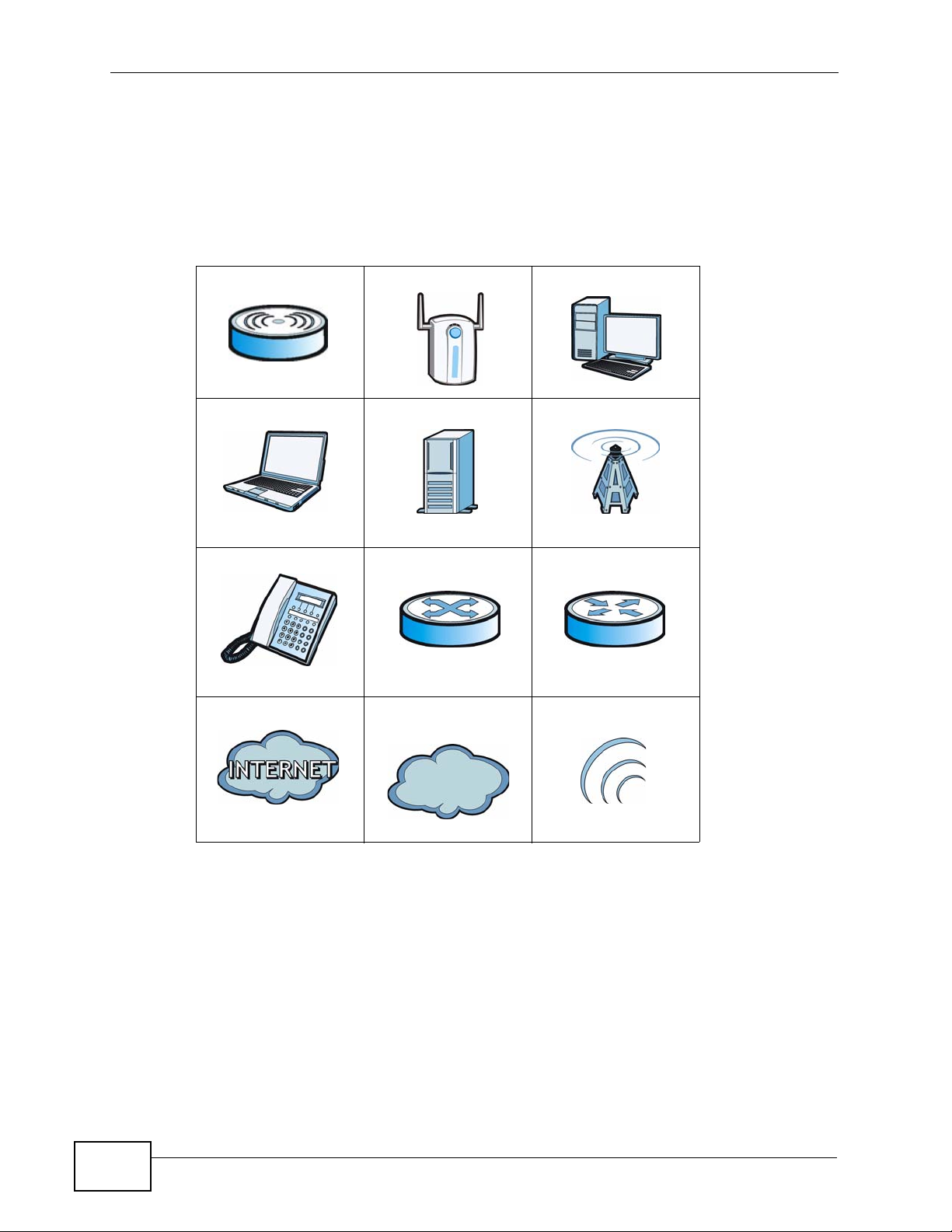
Icons Used in Figures
Figures in this User’s Guide may use the following generic icons. The MAX207HW2R icon is not an exact representation of your MAX-207HW2R.\
Table 1 Common Icons
WiMAX Device WiMAX Access Point Computer
Notebook Server WiMAX Base Station
Telephone Switch Router
Internet Cloud Internet/WiMAX
Cloud
Wireless Signal
6
MAX-207HW2R User’s Guide

Safety Warnings
Safety Warnings
• Do NOT use this product near water, for example, in a wet basement or near a swimming
pool.
• Do NOT expose your device to dampness, dust or corrosive liquids.
• Do NOT store things on the device.
• Do NOT install, use, or service this device during a thunderstorm. There is a remote risk
of electric shock from lightning.
• Connect ONLY suitable accessories to the device.
• Do NOT open the device or unit. Opening or removing covers can expose you to
dangerous high voltage points or other risks. ONLY qualified service personnel should
service or disassemble this device. Please contact your vendor for further information.
• Make sure to connect the cables to the correct ports.
• Place connecting cables carefully so that no one will step on them or stumble over them.
• Always disconnect all cables from this device before servicing or disassembling.
• Use ONLY an appropriate power adaptor or cord for your device. Connect it to the right
supply voltage (for example, 110V AC in North America or 230V AC in Europe).
• Do NOT remove the plug and connect it to a power outlet by itself; always attach the plug
to the power adaptor first before connecting it to a power outlet.
• Do NOT allow anything to rest on the power adaptor or cord and do NOT place the
product where anyone can walk on the power adaptor or cord.
• Do NOT use the device if the power adaptor or cord is damaged as it might cause
electrocution.
• If the power adaptor or cord is damaged, remove it from the device and the power
source.
• Do NOT attempt to repair the power adaptor or cord. Contact your local vendor to order a
new one.Do not use the device outside, and make sure all the connections are indoors.
There is a remote risk of electric shock from lightning.
• Do NOT obstruct the device ventilation slots, as insufficient airflow may harm your
device.Use only No. 26 AWG (American Wire Gauge) or larger telecommunication line
cord.
• Antenna Warning! This device meets ETSI and FCC certification requirements when using
the included antenna(s). Only use the included antenna(s).
• If you wall mount your device, make sure that no electrical lines, gas or water pipes will
be damaged.
• Make sure that the cable system is grounded so as to provide some protection against
voltage surges.
Your product is marked with this symbol, which is known as the WEEE mark.
WEEE stands for Waste Electronics and Electrical Equipment. It means that used
electrical and electronic products should not be mixed with general waste. Used
electrical and electronic equipment should be treated separately.
MAX-207HW2R User’s Guide
7

Safety Warnings
8
MAX-207HW2R User’s Guide

Contents Overview
Contents Overview
User’s Guide ........................................................................................................ ...................17
Getting Started ........................................................................................................................... 19
Introducing the Web Configurator .............................................................................................. 23
Technical Reference ..............................................................................................................29
The Setup Screens .................................................................................................................... 31
The Status Screen ..................................................................................................................... 39
The LAN Configuration Screens ................................................................................................ 43
The WIFI Configuration Screen ................................................................................................. 55
The WAN Configuration Screens ............................................................................................... 71
The Port Configuration Screens ................................................................................................ 83
The System Configuration Screens ........................................................................................... 89
The Service Configuration Screens ........................................................................................... 97
The Phone Screens ..................................................................................................................111
The Phone Book Screens ........................................................................................................ 121
The Certificates Screens ......................................................................................................... 127
The Remote Management Screens ......................................................................................... 135
The Firewall Screens ............................................................................................................... 145
Content Filter ............................................................ .... ... ... ... .... ... ........................................... 155
The Password Setup Screen ................................................................................................... 159
The Status Screen ................................................................................................................... 161
Troubleshooting ..................................................... .................................................................. 165
Product Specifications ............................................................................................................. 173
MAX-207HW2R User’s Guide
9

Contents Overview
10
MAX-207HW2R User’s Guide

Table of Contents
Table of Contents
About This User's Guide..........................................................................................................3
Document Conventions............................................................................................................5
Safety Warnings ........................................................................................................................7
Contents Overview ...................................................................................................................9
Table of Contents....................................................................................................................11
Part I: User’s Guide................................................................................ 17
Chapter 1
Getting Started........................................................................................................................19
1.1 About Your MAX-207HW2R ................................................................................................ 19
1.1.1 WiMAX Internet Access .............................................................................................19
1.1.2 Make Calls via Internet Telephony Service Provider .................................................. 20
1.2 MAX-207HW2R Hardware .................................................................................................. 21
1.2.1 LEDs ................................................... ... ... .... ............................................. ... ... ... ....... 21
1.3 Good Habits for Managing the MAX-207HW2R .................................................................. 22
Chapter 2
Introducing the Web Configurator ........................................................................................23
2.1 Overview ............. ............................................. ... .... ... ... ... .... ................................................ 23
2.1.1 Accessing the Web Configurator ................................................................................ 23
2.1.2 The Reset Button ....................................................................................................... 24
2.2 The Main Screen ................................................................................................................. 25
Part II: Technical Reference.................................................................. 29
Chapter 3
The Setup Screens..................................................................................................................31
3.1 Overview ............. ............................................. ... .... ... ... ... .... ................................................ 31
3.1.1 What You Can Do in This Chapter ............................................................................. 31
3.1.2 What You Need to Know ............................................................ ... ... ... .... ... ... ... ... .... ... 31
3.1.3 Before You Begin ................................ ... ... .... ... ... ....................................................... 32
3.2 LAN Configuration ................................. .... ... ... ... .... ... ... ... .... ... ............................................. 32
MAX-207HW2R User’s Guide
11

Table of Contents
3.3 DHCP Client .............................. ............................................. ... ... ... .... ... ... ... ....................... 33
3.4 Time Setting .................................................. ... ... .... ... ... ... .... ... ... .......................................... 35
3.4.1 Pre-Defined NTP Time Servers List .............................. ... ... ... .... ................................ 36
3.4.2 Resetting the Time . ... ... .... ... ... ... ............................................. .... ... ... ... .... ... ................ 37
Chapter 4
The Status Screen...................................................................................................................39
4.1 Overview ............. ............................................. ... .... ... ... ... .... ................................................ 39
4.2 Status Screen ............................................................ ... ... .................................................... 39
Chapter 5
The LAN Configuration Screens............................................................................................43
5.1 Overview ............. ............................................. ... .... ... ... ... .... ................................................ 43
5.1.1 What You Can Do in This Chapter ............................................................................. 43
5.1.2 What You Need to Know ............................................................ ... ... ... .... ... ... ... ... .... ... 43
5.2 DHCP Setup .............................................................. ... ... .................................................... 44
5.3 Static DHCP ..................................... ... ... .... ............................................. ... ... .... ... ................45
5.4 IP Alias ......................................... ... ... ... .............................................. ... ... ... .... ................... 47
5.5 Advanced ............... ... .... ............................................. ... ... .... ... ... ... ....................................... 49
5.6 Technical Reference ........... ... .... ... ... .................................................................................... 50
5.6.1 IP Address and Subnet Mask ..................................................................................... 50
5.6.2 DHCP Setup ..................... ... ... ... ... .... ... ... ... .............................................. ... ... ... ... .... ...51
5.6.3 LAN TCP/IP .................. .... ... ... ............................................. ... .... ... ............................. 51
5.6.4 DNS Server Address ................................. .... ... ... ... ............................................. .... ... 51
5.6.5 RIP Setup ............................................................................... .... ... ... ... .... ... ... .............52
5.6.6 Multicast . ... ... ... .............................................. ... ... ... ............................................. ....... 53
Chapter 6
The WIFI Configuration Screen .............................................................................................55
6.1 Overview ............. ............................................. ... .... ... ... ... .... ................................................ 55
6.1.1 What You Can Do in the WIFI Screens ...................................................................... 55
6.1.2 What You Need to Know About WIFI ............................................................... ... .... ... 56
6.1.3 Before You Start ........................ ............................................. .... ... ... ... .... ... ................59
6.2 General Screen .... ... .... ... ... ................................................................................................. 59
6.2.1 No Security .......................... ... ............................................. ... .... ... ... ... .... ................... 60
6.2.2 WEP Encryption ..... ... ... .... ... ... .................................................................................... 61
6.2.3 WPA(2)-PSK .............................................................................................................. 62
6.2.4 Wireless LAN Advanced Setup ................................................................................. 63
6.3 MAC Filter ....................................................................................................................... 64
6.4 WPS ... ... ... ............................................. .... ... ... ............................................. .... ... ................65
6.5 Wireless LAN Technical Reference ........................................ ... ... ... .... ... ... ... .... ... ... ... ... .......66
6.5.1 Additional Wireless Terms .......................................................................................... 66
6.5.2 Wireless Security Overview ....................................................................................... 66
12
MAX-207HW2R User’s Guide

Table of Contents
6.5.3 WiFi Protected Setup ................................................................................................. 68
Chapter 7
The WAN Configuration Screens...........................................................................................71
7.1 Overview ............. ............................................. ... .... ... ... ... .... ................................................ 71
7.1.1 What You Can Do in This Chapter ............................................................................. 71
7.1.2 What You Need to Know ............................................................ ... ... ... .... ... ... ... ... .... ... 71
7.2 Internet Connection ............................... .............................................................................. 73
7.3 WiMAX Configuration ................................................................................ ... .... ................... 75
7.3.1 Frequency Ranges ..................................................................................................... 78
7.3.2 Configuring Frequency Settings .................................................................................78
7.4 WiMAX FC Table .......................................................................................... .... ... ................80
Chapter 8
The Port Configuration Screens............................................................................................83
8.1 Overview ............. ............................................. ... .... ... ... ... .... ................................................ 83
8.1.1 What You Can Do in This Chapter ............................................................................. 83
8.2 General ............................ ... ... .... ... ... ............................................. ... .... ... ... ... ....................... 84
8.3 Port Forwarding .............................................................. .... ... ... ... ... .... ... ... ... ....................... 85
8.3.1 Port Forwarding Options ............................................................................................ 85
8.3.2 Port Forwarding Rule Setup ....................................................................................... 87
Chapter 9
The System Configuration Screens......................................................................................89
9.1 Overview ............. ............................................. ... .... ... ... ... .... ................................................ 89
9.1.1 What You Can Do in This Chapter ............................................................................. 89
9.1.2 What You Need to Know ............................................................ ... ... ... .... ... ... ... ... .... ... 89
9.2 Dynamic DNS ............................................................ ... ... .... ... ... .......................................... 90
9.3 Firmware ................ ... .... ....................................................................................................... 92
9.3.1 The Firmware Upload Process ............ ............. ............. ............. ............. ......... .......... 93
9.4 Configuration ............................. ... ... ... ... .............................................. ... ... ... .... ... ... .............93
9.4.1 The Restore Configuration Process ........................................................................... 94
9.5 Restart ............................................................. ... .... ... ... ... .... ................................................ 95
9.5.1 The Restart Process .................................................................................................. 95
Chapter 10
The Service Configuration Screens......................................................................................97
10.1 Overview ............................................................................................................................ 97
10.1.1 What You Can Do in This Chapter . .......................................................................... 97
10.1.2 What You Need to Know .......................................................................................... 97
10.1.3 Before you Begin .................................. .......... .......... ......... .......... .......... ......... ....... ... 99
10.2 SIP Settings ....................................................................................................................... 99
10.2.1 Advanced SIP Settings .......................................................................................... 100
MAX-207HW2R User’s Guide
13

Table of Contents
10.3 Technical Reference ........................................................................................................106
10.3.1 SIP Call Progression ..............................................................................................106
10.3.2 SIP Client Server .................................................................................................... 107
10.3.3 SIP User Agent ...................................................................................................... 107
10.3.4 SIP Proxy Server ..................... .......... .......... ......... .......... .......... ......... ....... ......... ..... 107
10.3.5 SIP Redirect Server ............................................................................................... 108
10.3.6 NAT and SIP .......................................................................................................... 109
10.3.7 DiffServ ..................................................................................................................109
10.3.8 DSCP and Per-Hop Behavior ..................................................................................110
Chapter 11
The Phone Screens...............................................................................................................111
11.1 Overview ...........................................................................................................................111
11.1.1 What You Can Do in This Chapter ..........................................................................111
11.1.2 What You Need to Know .........................................................................................111
11.2 Analog Phone ...................................................................................................................112
11.2.1 Advanced Analog Phone Setup ..............................................................................113
11.3 Common ...........................................................................................................................115
11.4 Region ...............................................................................................................................116
11.5 Technical Reference .........................................................................................................116
11.5.1 The Flash Key .........................................................................................................117
11.5.2 Europe Type Supplementary Phone Services .........................................................117
11.5.3 USA Type Supplementary Services ........................................................................119
Chapter 12
The Phone Book Screens.....................................................................................................121
12.1 Overview .......................................................................................................................... 121
12.1.1 What You Can Do in This Chapter . ........................................................................ 121
12.1.2 What You Need to Know ........................................................................................ 121
12.2 Call Forward Policy .......................................................................................................... 122
12.3 Speed Dial .......................................................................................................................124
12.3.1 Speed Dial Setup ...................................................................................................125
Chapter 13
The Certificates Screens......................................................................................................127
13.1 Overview .......................................................................................................................... 127
13.1.1 What You Can Do in This Chapter . ........................................................................ 127
13.1.2 What You Need to Know ........................................................................................ 127
13.2 My Certificates ................................................................................................................. 128
13.3 Trusted CAs ..................................................................................................................... 129
13.4 Technical Reference ........................................................................................................129
13.4.1 Certificate Authorities ............................................................................................. 130
13.4.2 Verifying a Certificate ............................................................................................. 132
14
MAX-207HW2R User’s Guide

Table of Contents
Chapter 14
The Remote Management Screens .....................................................................................135
14.1 Overview .......................................................................................................................... 135
14.1.1 What You Can Do in This Chapter . ........................................................................ 135
14.1.2 What You Need to Know ........................................................................................ 136
14.2 WWW .............................................................................................................................. 137
14.3 Telnet ............................................................................................................................... 138
14.4 FTP .................................................................................................................................. 139
14.5 SNMP ..............................................................................................................................140
14.5.1 SNMP Traps ........................................................................................................... 141
14.5.2 SNMP Options .......................................................................................................142
14.6 DNS ................................................................................................................................. 143
14.7 Ping ................................................................................................................................. 144
Chapter 15
The Firewall Screens............................................................................................................145
15.1 Overview .......................................................................................................................... 145
15.1.1 What You Can Do in This Chapter . ........................................................................ 145
15.1.2 What You Need to Know ........................................................................................ 145
15.2 Firewall Setting ................................................................................................................ 146
15.2.1 Firewall Rule Directions ......................................................................................... 146
15.2.2 Triangle Route ........................................................................................................ 147
15.2.3 Firewall Setting Options ......................................................................................... 148
15.3 Services ........................................................................................................................... 149
15.4 Technical Reference ........................................................................................................151
15.4.1 Stateful Inspection Firewall. ...................................................................................151
15.4.2 Guidelines For Enhancing Security With Your Firewall .......................................... 151
15.4.3 The “Triangle Route” Problem ........................................... ................................ ..... 151
Chapter 16
Content Filter.........................................................................................................................155
16.1 Overview .......................................................................................................................... 155
16.1.1 What You Can Do in This Chapter . ........................................................................ 155
16.2 Filter ................................................................................................................................. 156
16.3 Schedule .......................................................................................................................... 158
Chapter 17
The Password Setup Screen................................................................................................159
17.1 Overview .......................................................................................................................... 159
17.2 Password Setup .............................................................................................................. 159
Chapter 18
The Status Screen.................................................................................................................161
MAX-207HW2R User’s Guide
15

Table of Contents
18.1 Overview .......................................................................................................................... 161
18.2 Status Screen ..................................................................................................................161
Chapter 19
Troubleshooting....................................................................................................................165
19.1 Power, Hardware Connections, and LEDs ........................................................... ... ... .... . 165
19.2 MAX-207HW2R Access and Login .......... ... ............................................. ... .... ... ... ... ... .....166
19.3 Internet Access ................................................................................................................ 168
19.4 Phone Calls and VoIP ......................................................................................................170
19.5 Reset the MAX-207HW2R to Its Factory Defaults ... ... ... .... ... ... ... ... .................................. 171
19.5.1 Pop-up Windows, JavaScripts and Java Permissions ........................................... 171
Chapter 20
Product Specifications.........................................................................................................173
20.1 Wall-Mounting ..................................................................................................................180
20.1.1 The Wall-Mounting Kit ............................................................................................ 180
20.1.2 Instructions ............................................................................................................. 180
Appendix A WiMAX Security................................................................................................183
Appendix B Setting Up Your Computer’s IP Address...........................................................187
Appendix C Pop-up Windows, JavaScripts and Java Permissions......................................215
Appendix D IP Addresses and Subnetting...........................................................................225
Appendix E Importing Certificates........................................................................................237
Appendix F SIP Passthrough...............................................................................................269
Appendix G Common Services............................................................................................271
Appendix H Legal Information..............................................................................................275
Index.......................................................................................................................................279
16
MAX-207HW2R User’s Guide

PART I
User’s Guide
17

18
CHAPTER 1
Getting Started
1.1 About Your MAX-207HW2R
The MAX-207HW2R has a built-in switch and one phone port. It allows you to
access the Internet by connecting to a WiMAX wireless network.
You can use a traditional analog telephone to make Internet calls using the MAX207HW2R’s Voice over IP (VoIP) communication capabilities.
You can configure firewall and content filtering as well as a host of other features.
The web browser-based Graphical User Interface (GUI), also known as the web
configurator, provides easy management.
See Chapter 20 on page 173 for a complete list of features for your model.
1.1.1 WiMAX Internet Access
Connect your computer or network to the MAX-207HW2R for WiMAX Internet
access. See the Quick Start Guide for instructions on hardware connection.
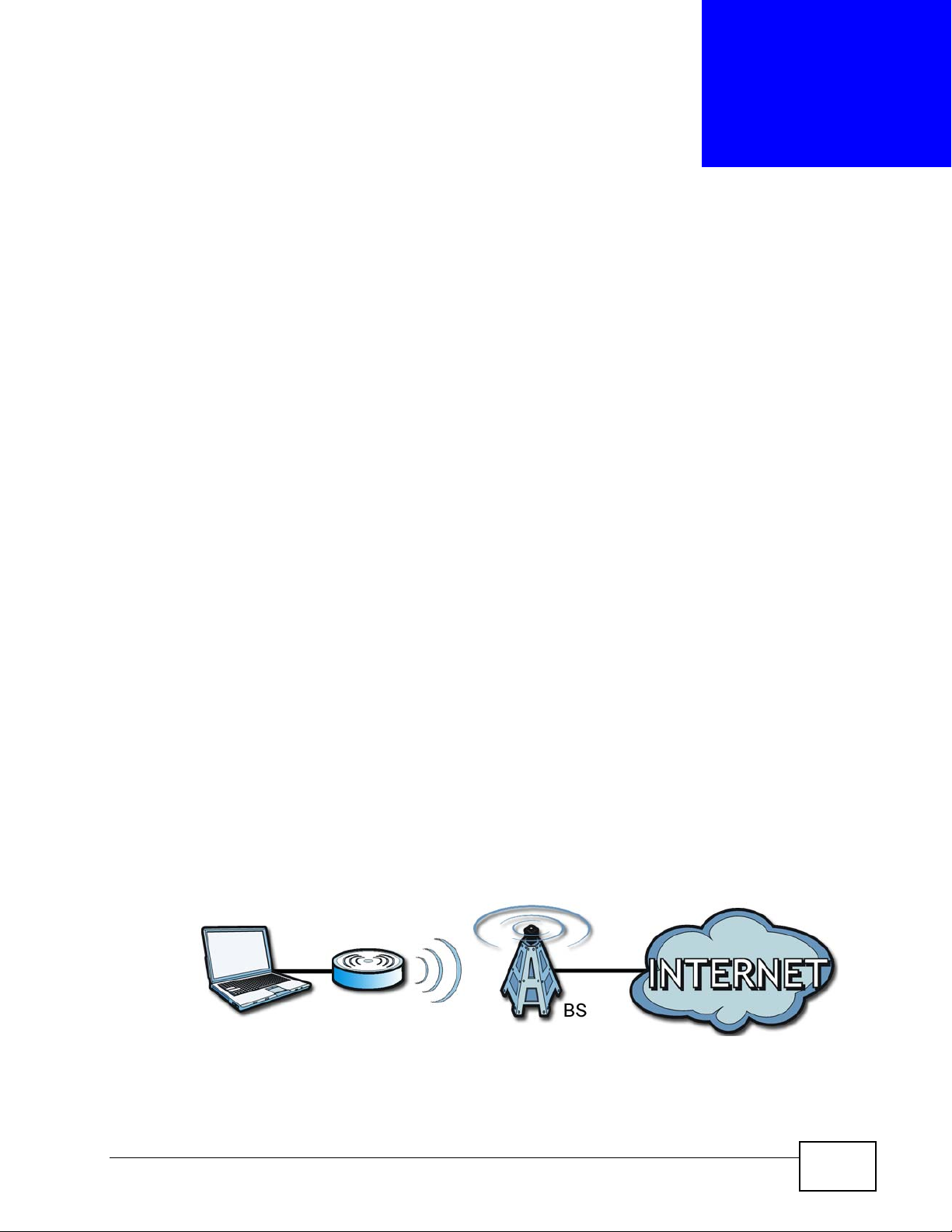
In a wireless metropolitan area network (MAN), the MAX-207HW2R connects to a
WiMAX base station (BS) for Internet access.
The following diagram shows a notebook computer equipped with the MAX207HW2R connecting to the Internet through a WiMAX base station (marked BS).
Figure 1 Mobile Station and Base Station
When the firewall is on, all inc o m ing traffic from the Internet to your network is
blocked unless it is initiated from your network.
MAX-207HW2R User’s Guide
19
Chapter 1 Getting Started
Use content filtering to block access to web sites with URLs containing keywords
that you specify. You can define time periods and days during which content
filtering is enabled and include or exclude particular computers on your network
from content filtering. For example, you could bloc k access to certain web sites for
the kids.
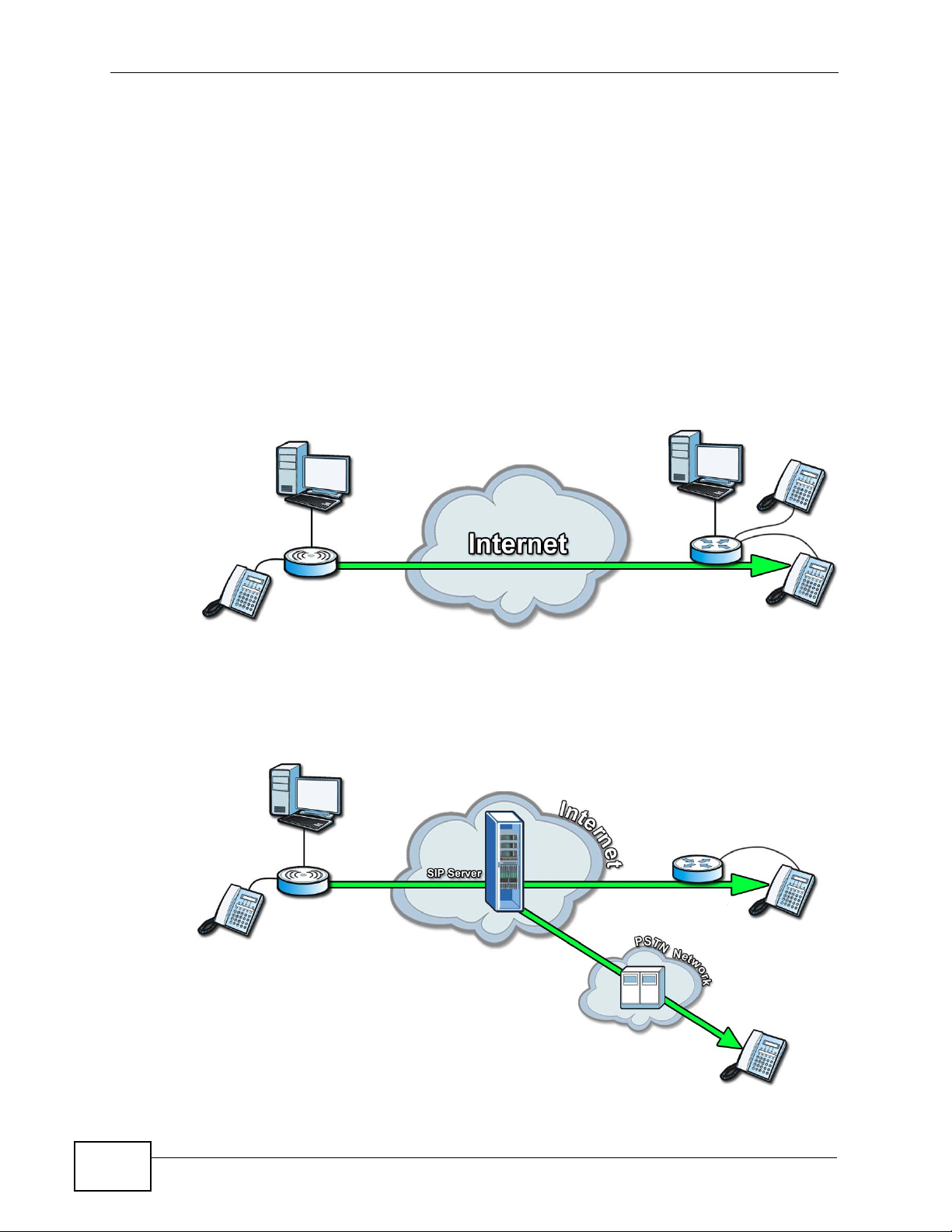
1.1.2 Make Calls via Internet Telephony Service Provider
In a home or small office environment, you can use the MAX-207HW2R to make
and receive the following types of VoIP telephone calls:
• Peer-to-Peer calls - Use the MAX-207HW2R to make a call directly to the
recipient’s IP address without using a SIP proxy server.
Figure 2 MAX-207HW2R’s VoIP Features - Peer-to-Peer Calls
• Calls via a VoIP service provider - The MAX-207HW2R sends your call to a VoIP
service provider’s SIP server which forwards your calls to either VoIP or PSTN
phones.
Figure 3 MAX-207HW2R’s VoIP Features - Calls via VoIP Service Provider
20
MAX-207HW2R User’s Guide
1.2 MAX-207HW2R Hardware
Follow the instructions in the Quick Start Guide to make hardware connections.
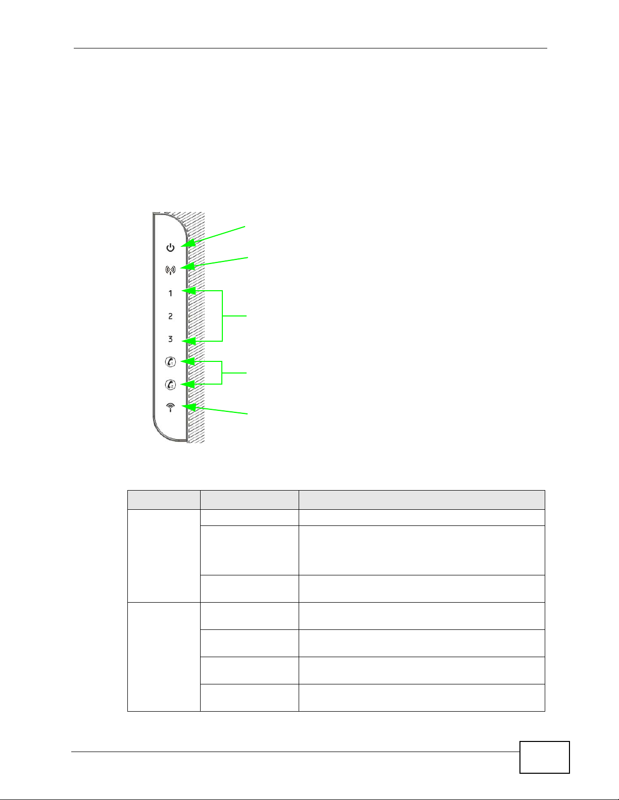
1.2.1 LEDs
The following figure shows the LEDs (lights) on the MAX-207HW2R.
Figure 4 The MAX-207HW2R’s LEDs
POWER
LED
WIMAX
LINK
SIGNAL
STRENGTH
INDICATORS
Chapter 1 Getting Started
VOICE
LEDS
1 & 2
WLAN
LED
The following table describes your MAX-207HW2R’s LEDs (from right to left).
Table 2 The MAX-207HW2R
LED STATE DESCRIPTION
Power Off The MAX-207HW2R is not receiving power.
Red The MAX-207HW2R is receiving power but has been
unable to start up correctly or is not receiving
enough power. See the Troubleshooting section for
more information.
Green The MAX-207HW2R is receiving power and
functioning correctly.
WiMAN Link Off The MAX-207HW2R is not connected to a wireless
(WiMAX) network.
Green The MAX-207HW2R is successfully connected to a
wireless (WiMAX) network.
Green (Blinking
Slowly)
Green (Blinking
Quickly)
The MAX-207HW2R is searching for a wireless
(WiMAX) network.
The MAX-207HW2R has found a wireless (WiMAX)
network and is connecting.
MAX-207HW2R User’s Guide
21
Chapter 1 Getting Started
Table 2 The MAX-207HW2R
LED STATE DESCRIPTION
Signal
Strength
Indicator
Voice Off No SIP account is registered, or the MAX-207HW2R
WLAN Off The Wi-Fi network is not operational.
The Strength Indicator LEDs display the Interference-plus-Noise Ratio
(CINR) of the wireless (WiMAX) connection.
Signal 1 On The signal strength is in the range between 5 and
15.
Signal 2 On The signal strength is in the range between 16 and
24.
Signal 3 On The signal strength is greater than or equal to 25
dBm
is not receiving power.
Green A SIP account is registered.
Green (Blinking) A SIP account is registered, and the phone attached
to the LINE port is in use (off the hook).
Yellow A SIP account is registered and has a voice
message on the SIP server.
Yellow (Blinking) A SIP account is registered and has a voice
message on the SIP server, and the phone attached
to the LINE port is in use (off the hook).
Green The Wi-Fi network is operational.
Blinking Green The WiMAX Device is sending and receiving data
across the Wi-Fi network.
1.3 Good Habits for Managing the MAX207HW2R
Do the following things regularly to make the MAX-207HW2R more secure and to
manage the MAX-207HW2R more effectivel y.
• Change the password. Use a password that’s not easy to guess and that consists
of different types of characters, such as numbers and letters.
• Write down the password and put it in a safe place.
• Back up the configuration (and make sure you know how to restore it).
Restoring an earlier working configuration may be useful if the MAX-207HW2R
becomes unstable or even crashes. If you forget yo ur password, you will have to
reset the MAX-207HW2R to its factory default settings. If you backed up an
earlier configuration file, you would not have to totally re-configure the MAX207HW2R. You could simply restore your last configuration.
22
MAX-207HW2R User’s Guide

CHAPTER 2
Introducing the Web
Configurator
2.1 Overview
The web configurator is an HTML-based management interface that allows easy
device set up and management via any web browser that supports: HTML 4.0,
CSS 2.0, and JavaScript 1.5, and higher. The recommended screen resolution for
using the web configurator is 1024 by 768 pixels and 16-bit color, or higher.
In order to use the web configurator you need to allow:
• Web brows er pop-up windows from your device. W eb pop-up blocking i s enabled
by default in many operating systems and web browsers.
• JavaScript (enabled by default in most web browsers).
• Java permissions (enabled by default in most web browsers).
See the Appendix C on page 215 for more information on configuring your web
browser.
2.1.1 Accessing the Web Configurator
1 Make sure your MAX-207HW2R hardware is properly connected (refer to the Quick
Start Guide for more information).
2 Launch your web browser.
3 Enter "192.168.1.1" as the URL.
MAX-207HW2R User’s Guide
23
Chapter 2 Introducing the Web Configurator
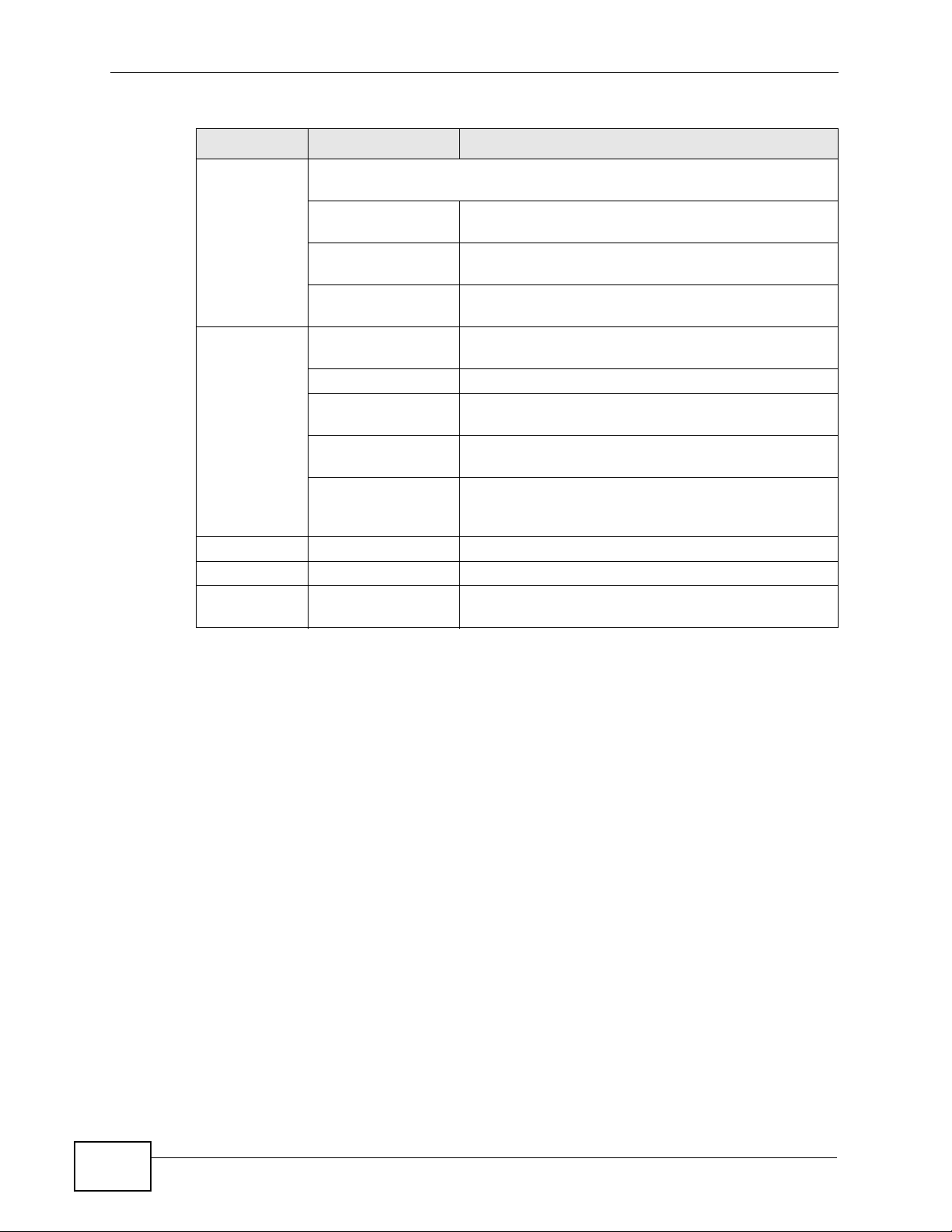
4 A login screen displays. Enter the default User Name (admin) and Password
(1234), and then click Login.
Figure 5 Password Screen
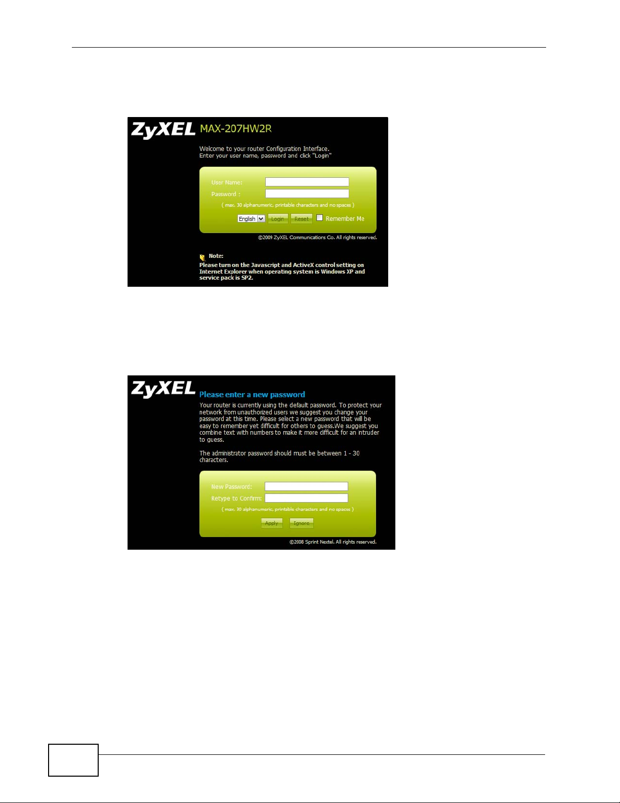
5 The following screen displays if you have not yet changed your password. It is
highly recommended you change the default password. Enter a new password,
retype it to confirm and click Apply; alternatively click Ignore to proceed to the
main menu if you do not want to change the password now.
Figure 6 Change Password Screen
2.1.2 The Reset Button
If you forget your password or cannot access the web configurator, you will need
to use the Reset button to reload the factory-default configur ation file. This
means that you will lose all configurations that you had previously and the
password will be reset to “1234”.
2.1.2.1 Using The Reset Button
1 Make sure the Power light is on (not blinking).
24
MAX-207HW2R User’s Guide
2 To set the device back to the factory default settings, press the Reset button for
ten seconds or until the Power light begins to blink and then release it. When the
Power light begins to blink, the defaults have been restored and the device
restarts.
3 Reconfigure the MAX-207HW2R foll owing the steps in your Quick Start Guide.
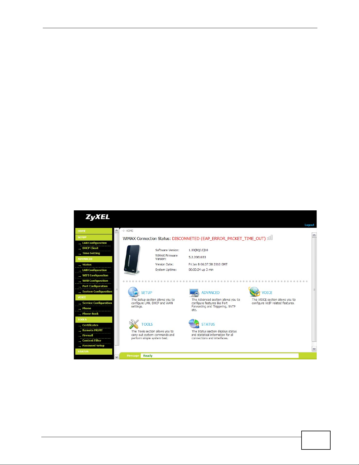
2.2 The Main Screen
When you first log into the web configurator and by-pass the wizard, the Main
screen appears. Here you can view a concise summary of your MAX-207HW2R
connection status. This is also the default “home” page for the ZyXEL web
configurator and it contains conveniently-placed shortcuts to all of the other
screens.
Note: Some features in the web configurator may not be available depe ndin g on you r
firmware version and/or configuration.
Chapter 2 Introducing the Web Configurator
Figure 7 Main Screen
MAX-207HW2R User’s Guide
25
Chapter 2 Introducing the Web Configurator
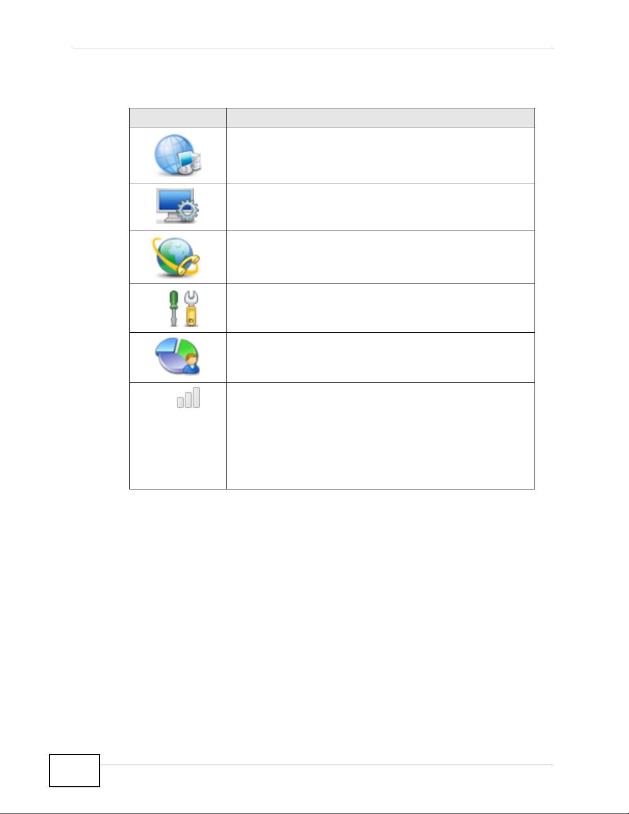
The following table describes the icons in this screen.
Table 3 Main > Icons
ICON DESCRIPTION
SETUP
Click to go the Setup screen, where you can configure LAN,
DHCP and WAN settings.
ADVANCED
Click to go to the Advanced screen, where you can configure
features like Port Forwarding and Triggering, SNTP and so on.
VOICE
Click to go to the Voice screen, where you can configure your
voice service and phone settings .
TOOLS
Click to go the Tools screen, where you can configure your
firewall, QoS, and content filter, among other things.
STATUS
Click to go to the Status screen, where you can view status and
statistical information for all connections and interfaces.
Strength Indicator
Displays a visual representation of the quality of your WiMAX
connection.
• Disconnected - Zero bars
• Poor reception - One bar
• Good reception - Two bars
• Excellent reception - Three bars
26
MAX-207HW2R User’s Guide
Chapter 2 Introducing the Web Configurator
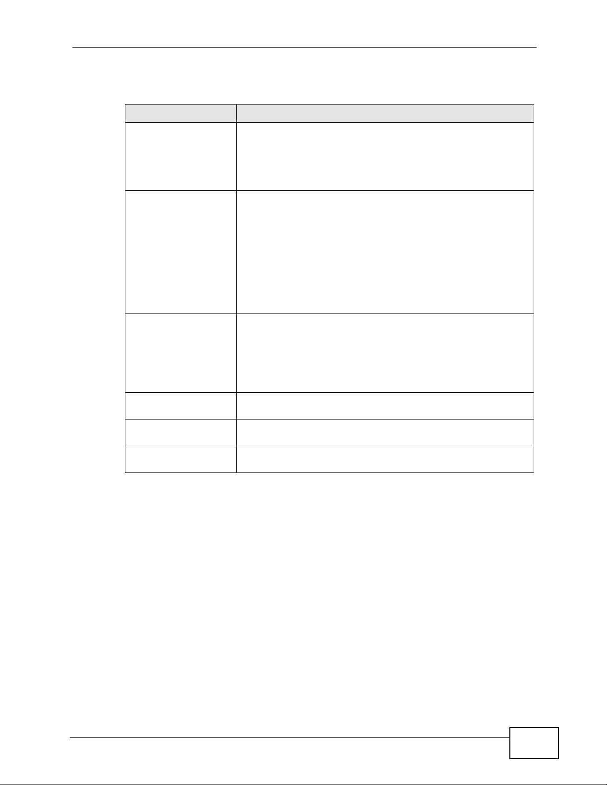
The following table describes the labels in this screen.
Table 4 Main
LABEL DESCRIPTION
Logout Click to log out of the Web Configurator.
Note: This does not log you off the WiMAX network, it simply
logs you out of the MAX-207HW2R’s browser-based
configuration interface.
WiMAX Connection
Status
Software Version This field indicates the version number of the MAX-207HW2R’s
This field indicates the current status of your WiMAX connection.
Status messages are as follows:
• Connected - Indicates that the MAX-207HW2R is connected
to the WiMAX network. Use the Strength Indicator icon to
determine the quality of your network connection.
• Disconnected - Indicates that the MAX-207HW2R is not
connected to the WiMAX network.
• DL_SYN - Indicates a download synchronization is in
progress. This means the firmware is checking with the
server for any updates or settings alterations.
firmware. The version number takes the form of: Version
(Build),release status (candidate) | Version Release Date.
For example: V3.60(BCC.0)c4 | 07/08/2008 indicates that the
firmware is 3.60, build BCC.0, candidate4, released on July 08,
2008.
WiMAX Firmware
Version
Version Date This field indicates the exact date and time the current firmware
System Uptime This field indicates how long the MAX-207HW2R has been on.
This field displays the version number of the chip firmware used
in this MAX-207HW2R.
was compiled.
This resets every time you shut the device down or restart it.
Note: For security reasons, the MAX-207HW2R automatically logs you out if you do
not use the web configurator for five minutes. If this happens, simply log in
again.
MAX-207HW2R User’s Guide
27

Chapter 2 Introducing the Web Configurator
28
MAX-207HW2R User’s Guide

PART II
Technical Reference
29

30

CHAPTER 3
The Setup Screens
3.1 Overview
Use these screens to configure or view LAN, DHCP Client and WAN settings.
3.1.1 What You Can Do in This Chapter
•The LAN Configuration screen (Section 3.2 on page 32) lets you configure the
MAX-207HW2R’s IP address and subnet mask.
•The DHCP Client screen (Section 3.3 on page 33) lets you view all DHCP client
information.
•The Time Setting screen (Section 3.4 on page 35) lets you configure your
MAX-207HW2R’s time and date keeping settings.
3.1.2 What You Need to Know
The following terms and concepts may help as you read through this chapter.
LAN
A Local Area Network, or a shared communication system to which many
computers are attached. A LAN, as its name implies, is limited to a local area such
as a home or office environment. LANs have different topologies, the most
common being the linear bus and the star configuration.
IP Address
IP addresses identify individual devices on a network. Every networking device
(including computers, servers, routers, printers, etc.) needs an IP address to
communicate across the network. These networking devices are also known as
hosts.
Subnet Mask
The subnet mask specifies the network number portion of an IP address. Your
device will compute the subnet mask automatically based on the IP Address that
MAX-207HW2R User’s Guide
31

Chapter 3 The Setup Screens
you entered. Y ou do not need to change the computer subnet mask unless you are
instructed to do so.
DHCP
Your WiMAX Modem can act as a DHCP (Dynamic Host Configuration Protocol)
server that can assign your LAN computers an IP address, subnet mask, DNS and
other routing information when its LAN DHCP feature is turned on.
Daytime
A network protocol used by devices for debugging and time measurement. A
computer can use this protocol to set its internal clock but only if it knows in which
order the year, month, and day are returned by the server. Not all servers use the
same format.
Time
A network protocol for retrieving the current time from a server. The computer
issuing the command compares the time on its clock to the information returned
by the server, adjusts itself automatically for time zone differences, then
calculates the difference and corrects itself if there has been any temporal drift.
NTP
NTP stands for Network Time Protocol. It is employed by devices connected to the
Internet in order to obtain a precise time setting from an official time server.
These time servers are accurate to within 200 microseconds.
3.1.3 Before You Begin
• Make sure that you have made all the appropriate hardware connections to the
MAX-207HW2R, as described in the Quick Start Guide.
• Make sure that you have logg ed in to the web confi gurator at least one time and
changed your password from the de fau lt , as de s cr ib ed in the Quick Start Guide.
3.2 LAN Configuration
Click the SETUP icon in the navigation bar to set up the MAX-207HW2R’s IP
address and subnet mask. This screen displays this screen by default. If you are in
32
MAX-207HW2R User’s Guide

Chapter 3 The Setup Screens
any other sub-screen you can simply choose Set IP Address from the navigation
menu on the left to open it again.
Figure 8 SETUP > Set IP Address
The following table describes the labels in this screen.
Table 5 SETUP > Set IP Address
LABEL DESCRIPTION
IP Address Enter the IP address of the MAX-207HW2R on the LAN.
IP Subnet Mask Enter the subnet mask of the LAN.
Apply
Reset Click to restore your previously saved settings.
3.3 DHCP Client
Click SETUP > DHCP Client to display the IP addresses, Host Names and MAC
addresses of the devices currently connected to the MAX-207HW2R. These
Note: This field is the IP address you use to access the
MAX-207HW2R on the LAN. If the web configurator is
running on a computer on the LAN, you lose access to
it as soon as you change this field and click Apply.
You can access the web configurator again by typing
the new IP address in the browser.
Click to save your changes.
MAX-207HW2R User’s Guide
33

Chapter 3 The Setup Screens
settings can be configured in the ADVANCED > LAN Configuration > DHCP
Setup screen.
Figure 9 SETUP > DHCP Client
The following table describes the labels in this screen.
Table 6 SETUP > DHCP Client
LABEL DESCRIPTION
# The number of the item in this list.
IP Address This field displays the IP address the MAX-207HW2R assigned to
a computer in the network.
Host Name This field displays the system name of the computer to which
the MAX-207HW2R assigned the IP address.
MAC Address This field displays the MAC address of the computer to which the
MAX-207HW2R assigned the IP address.
Reserve Select Reserve and click Apply to have the MAX-207HW2R
always map the currently assigned IP address to the device with
this MAC address.
Apply
Refresh
Clear Reserve and click Apply to allow the MAX-207HW2R to
assign a new IP address to this device with this MAC address
when next time the device sends a new DHCP request.
Click this button to update the table data.
34
MAX-207HW2R User’s Guide

3.4 Time Setting
Click SETUP > Time Setting to set the date, time, and time zone for the MAX207HW2R.
Figure 10 SETUP > Time Setting
Chapter 3 The Setup Screens
The following table describes the labels in this screen.
Table 7 SETUP > Time Setting
LABEL DESCRIPTION
Current Time and Date
Current Time Displays the current time according to the MAX-207HW2R.
Current Date Displays the current time according to the MAX-207HW2R.
Time and Date Setup
Manual
New Time Enter the new time in this field, and click Apply.
New Date
Get from Time Server Select this if you want to use a time server to update the current
MAX-207HW2R User’s Guide
Select this if you want to specify the current date and time in the
fields below.
Enter the new date in this field, and click Apply .
date and time in the MAX-207HW2R.
35

Chapter 3 The Setup Screens
Table 7 SETUP > Time Setting
LABEL DESCRIPTION
Time Protocol Select the time service protocol that your time server
Time Server
Address
Time Zone Setup
Time Zone Select the time zone at your location.
Daylight Savings Select this if your location uses daylight savings time. Daylight
Start Date Enter which hour on which day of which week of which month
End Date Enter which hour on the which day of which week of which
Apply
Reset Click to restore your previously saved settings.
uses.Check with your ISP or network administrator, or use trialand-error to find a protocol that works.
Daytime (RFC 867) - This format is day/month/year/time
zone.
Time (RFC 868) - This format displays a 4-byte integer giving
the total number of seconds since 1970/1/1 at 0:0:0.
NTP (RFC 1305) - This format is similar to Time (RFC 868).
Enter the IP address or URL of your time server . Check with your
ISP or network administrator if you are unsure of this
information.
savings is a period from late spring to early fall when many
places set their clocks ahead of normal local time by one hour to
give more daytime light in the evening.
daylight-savings time starts.
month daylight-savings time ends.
Click to save your changes.
3.4.1 Pre-Defined NTP Time Servers List
The MAX-207HW2R uses a pre-defined list of NTP time servers if you do not
specify a time server or it cannot synchronize with the time server you specified.
It can use this list regardless of the time protocol you select.
When the MAX-207HW2R us es the li st, it randomly selects one server and tries to
synchronize with it. If the synchronization fails, then it goes through the rest of
the list in order until either it is successful or all the pre-defined NTP time servers
have been tried.
Table 8 Pre-defined NTP Time Servers
ntp1.cs.wisc.edu
ntp1.gbg.netnod.se
ntp2.cs.wisc.edu
tock.usno.navy.mil
ntp3.cs.wisc.edu
ntp.cs.strath.ac.uk
ntp1.sp.se
36
MAX-207HW2R User’s Guide

Table 8 Pre-defined NTP Time Servers (continued)
time1.stupi.se
tick.stdtime.gov.tw
tock.stdtime.gov.tw
time.stdtime.gov.tw
3.4.2 Resetting the Time
The MAX-207HW2R automatically resets the time in the following circumstances:
• When the device starts up, such as when you press the Power button.
• When you click Apply in the SETUP > Time Setting screen.
• Once every 24-hours after starting up.
Chapter 3 The Setup Screens
MAX-207HW2R User’s Guide
37

Chapter 3 The Setup Screens
38
MAX-207HW2R User’s Guide

CHAPTER 4
The Status Screen
4.1 Overview
Use this screen to view a complete summary of your MAX-207HW2R connection
status.
4.2 Status Screen
Click Advanced > STATUS in the navigation bar to go to this screen, where you
can view the current status of the device, system resources, interfaces (LAN and
WAN), and SIP accounts. You can also register and un-register SIP accounts as
well as view detailed information from DHCP and statistics from WiMAX, VoIP,
bandwidth management, and traffic.
Figure 11 Advanced > Status
The following tables describe the labels in this screen.
Table 9 Advanced > Status
LABEL DESCRIPTION
Refresh Interval Select how often you want the MAX-207HW2R to update this screen.
Refresh Now Click this to update this screen immediately.
MAX-207HW2R User’s Guide
39

Chapter 4 The Status Screen
Table 9 Advanced > Status (continued)
LABEL DESCRIPTION
Device Information
System Name This field displays the MAX-207HW2R system name. It is used for
Software
Version
Bootbase
Version
Kernel Version This field displays the current kernel version inside the device.
WAN Information
IP Address This field displays the current IP address of the MAX-207HW2R in the
IP Subnet Mask This field displays the current subnet mask on the WAN.
DHCP This field displays what DHCP services the MAX-207HW2R is using in
identification.
This field displays the current firmware version inside the device.
You can change the firmware version by uploading new firmware in
ADVANCED > System Configuration > Firmware.
This field displays the current bootbase version inside the device.
WAN.
the WAN. Choices are:
Client - The MAX-207HW2R is a DHCP client in the WAN. Its IP
address comes from a DHCP server on the WAN.
None - The MAX-207HW2R is not using any DHCP services in the
WAN. It has a static IP address.
LAN Information
IP Address This field displays the current IP address of the MAX-207HW2R in the
LAN.
IP Subnet Mask This field displays the current subnet mask in the LAN.
DHCP This field displays what DHCP services the MAX-207HW2R is providing
to the LAN. Choices are:
Server - The MAX-207HW2R is a DHCP server in the LAN. It assigns
IP addresses to other computers in the LAN.
Relay - The MAX-207HW2R is ro uting DHCP requests to one or more
DHCP servers. The DHCP server(s) may be on another network.
None - The MAX-207HW2R is not providing any DHCP services to
the LAN.
You can change this in ADVANCED > LAN Configuration > DHCP
Setup.
WiMAX Information
CINR Mean This field shows the average Carrier to Interference plus Noise Ratio of
the current connection. This value is an indication of over all radio signal
quality. A higher value indicates a higher signal quality, and a lower
value indicates a lower signal quality.
CINR Deviation This field shows the amount of change in the CINR level. This value is
an indication of radio signal stability. A lower number indicates a more
stable signal, and a higher number indicates a less stable signal.
40
MAX-207HW2R User’s Guide

Chapter 4 T he Status Screen
Table 9 Advanced > Status (continued)
LABEL DESCRIPTION
RSSI This field shows the Received Signal Strength Indication. This value is a
measurement of overall radio signal strength. A higher RSSI level
indicates a stronger signal, and a lower RSSI level indicates a weaker
signal.
A strong signal does not necessarily indicate a good signal: a strong
signal may have a low signal-to-noise ratio (SNR).
Interface Status
Interface This column displays each interface of the MAX-207HW2R.
Status This field indicates whether or not the MAX-207HW2R is using the
interface.
For the WAN interface, this field displays Up when the MAX -207HW2R is
connected to a WiMAX network, and Down when the MAX-207HW2R is
not connected to a WiMAX network.
For the LAN interface, this field displays Up when the MAX-207HW2R is
using the interface and Down when the MAX-207HW2R is not using the
interface.
MAX-207HW2R User’s Guide
41

Chapter 4 The Status Screen
42
MAX-207HW2R User’s Guide

CHAPTER 5
The LAN Configuration Screens
5.1 Overview
Use the ADVANCED > LAN Configuration screens to set up the MAX-207HW2R
on the LAN. You can configure its IP addr ess and subnet mask, DHCP services, and
other subnets. You can also control how the MAX-207HW2R sends routing
information using RIP.
A Local Area Network (LAN) is a shared communication system to which many
computers are attached. A LAN is usually a computer network limited to the
immediate area, such as the same building or floor of a building.
5.1.1 What You Can Do in This Chapter
•The DHCP Setup screen (Section 5.2 on page 44) lets you enable, disable, and
configure the DHCP server in the MAX-207HW2R.
•The Sta tic DHCP sc reen (Section 5.3 on page 45) lets you assign specific IP
addresses to specific computers on the LAN.
•The IP Alias screen (Section 5.4 on page 47) lets you add subnets on the LAN
port. You can also control what routing information is sent and received by each
subnet.
•The Advanced screen (Section 5.5 on page 49) lets you control the routing
information that is sent and received by each subnet assign specific IP
addresses to specific computers on the LAN.
5.1.2 What You Need to Know
The following terms and concepts may help as you read through this chapter.
IP Address
IP addresses identify individual devices on a network. Every networking device
(including computers, servers, routers, printers, etc.) needs an IP address to
communicate across the network. These networking devices are also known as
hosts.
MAX-207HW2R User’s Guide
43

Chapter 5 The LAN Configuration Screens
Subnet Masks
Subnet masks determine the maximum number of possible hosts on a network.
You can also use subnet masks to divide one network into multiple sub-networks.
DNS
DNS (Domain Name System) is for mapping a domain name to its corresponding
IP address and vice versa. The DNS server is extremely important because
without it, you must know the IP address of a networking device before you can
access it.
DHCP
A DHCP (Dynamic Host Configuration Protocol) server can assign your MAX207HW2R an IP address, subnet mask, DNS and other routing information when
it’s turned on.
5.2 DHCP Setup
Click ADVANCED > LAN Configuration > DHCP Setup to enable, disable, and
configure the DHCP server in the MAX-207HW2R.
Figure 12 ADVANCED > LAN Configuration > DHCP Setup
44
MAX-207HW2R User’s Guide

Chapter 5 The LAN Configuration Screens
The following table describes the labels in this screen.
Table 10 ADVANCED > LAN Configuration > DHCP Setup
LABEL DESCRIPTION
DHCP Setup
Enable DHCP
Server
IP Pool Starting
Address
Pool Size Enter the number of IP addresses to allocate. This number must be at
lease time
(second)
DNS Server
First, Second
and Third DNS
Server
Select this if you want the MAX-207HW2R to be the DHCP server on the
LAN. As a DHCP server, the MAX-207HW2R assigns IP addresses to
DHCP clients on the LAN and provides the subnet mask and DNS server
information.
Enter the IP address from which the MAX-207HW2R begins allocating IP
addresses, if you have not specified an IP address for this computer in
ADVANCED > LAN Configuration > Static DHCP.
least one and is limited by a subnet mask of 255.255.255.0 (regardless
of the subnet the MAX-207HW2R is in). For example, if the IP Pool
Start Address is 10.10.10.10, the MAX-207HW2R can allocate up to
10.10.10.254, or 245 IP addresses.
You can assign the DHCP lease time by entering the seconds manually.
The lease time must be 120 seconds or more.
Specify the IP addresses of a maximum of three DNS servers that the
network can use. The MAX-207HW2R provides these IP addresses to
DHCP clients. You can specify these IP addresses two ways.
From ISP - provide the DNS servers provided by the ISP on the WAN
port.
User Defined - enter a static IP address.
DNS Relay - this setting will relay DNS information from the DNS
server obtained by the MAX-207HW2R.
None - no DNS service will be provided by the MAX-207HW2R.
Apply
Reset
Click to save your changes.
Click to restore your previously saved settings.
5.3 Static DHCP
Click ADVANCED > LAN Configuration > Static DHCP to assign specific IP
addresses to specific computers on the LAN.
MAX-207HW2R User’s Guide
45

Chapter 5 The LAN Configuration Screens
Note: This screen has no effect if the DHCP server is not enabled. You can enable it
in ADVANCED > LAN Configuration > DHCP Setup.
Figure 13 ADVANCED > LAN Configuration > Static DHCP
The following table describes the labels in this screen.
Table 11 ADVANCED > LAN Configuration > Static DHCP
LABEL DESCRIPTION
# The number of the item in this list.
MAC Address Enter the MAC address of the computer to which you want the MAX-
207HW2R to assign the same IP address.
IP Address Enter the IP address you want the MAX-207HW2R to assign to the
computer.
Apply Click to save your changes.
Reset
Click to restore your previously saved settings.
46
MAX-207HW2R User’s Guide

5.4 IP Alias
Click ADVANCED > LAN Configuration > IP Alias to add subnets on the LAN
port. You can also control what routing information is sent and received by each
subnet.
Figure 14 ADVANCED > LAN Configuration> IP Alias
Chapter 5 The LAN Configuration Screens
The following table describes the labels in this screen.
Table 12 ADVANCED > LAN Configuration> IP Alias
LABEL DESCRIPTION
IP Alias 1
IP Alias 1 Select this to add the specified subnet to the LAN port.
IP Address
IP Subnet
Mask
RIP
Direction
Enter the IP address of the MAX-207HW2R on the subnet.
Enter the subnet mask of the subnet.
Use this field to control how much routing information the MAX-
207HW2R sends and receives on the subnet.
• None - The MAX-207HW2R does not send or receive routing
information on the subnet.
• Both - The MAX-207HW2R sends and receives routing information
on the subnet.
• In Only - The MAX-207HW2R only receives routing information on
the subnet.
• Out Only - The MAX-207HW2R only sends routing information on
the subnet.
MAX-207HW2R User’s Guide
47

Chapter 5 The LAN Configuration Screens
Table 12 ADVANCED > LAN Configuration> IP Alias (continued)
LABEL DESCRIPTION
RIP Version Select which version of RIP the MAX-207HW2R uses when it sends or
receives information on the subnet.
• RIP-1 - The MAX-207HW2R us es R I Pv1 to exchange routing
information.
• RIP-2B - The MAX-207HW2R broadcasts RIPv2 to exchange routing
information.
• RIP-2M - The MAX-207HW2R multicasts RIPv2 to exchange routing
information.
IP Alias 2
IP Alias 2
IP Address Enter the IP address of the MAX-207HW2R on the subnet.
IP Subnet
Mask
RIP
Direction
RIP Version
Select this to add the specified subnet to the LAN port.
Enter the subnet mask of the subnet.
Use this field to control how much routing information the MAX207HW2R sends and receives on the subnet.
• None - The MAX-207HW2R does not send or receive routing
information on the subnet.
• Both - The MAX-207HW2R sends and receives routing information
on the subnet.
• In Only - The MAX-207HW2R only receives routing information on
the subnet.
• Out Only - The MAX-207HW2R only sends routing information on
the subnet.
Select which version of RIP the MAX-207HW2R uses when it sends or
receives information on the subnet.
Apply
Reset
• RIP-1 - The MAX-207HW2R us es R I Pv1 to exchange routing
information.
• RIP-2B - The MAX-207HW2R broadcasts RIPv2 to exchange routing
information.
• RIP-2M - The MAX-207HW2R multicasts RIPv2 to exchange routing
information.
Click to save your changes.
Click to restore your previously saved settings.
48
MAX-207HW2R User’s Guide

5.5 Advanced
Click ADVANCED > LAN Configuration > Advanced to set the RIP and
Multicast options.
Figure 15 ADVANCED > LAN Configuration > Advanced
Chapter 5 The LAN Configuration Screens
The following table describes the labels in this screen.
Table 13 ADVANCED > LAN Configuration > Advanced
LABEL DESCRIPTION
RIP & Multicast Setup
RIP Direction
RIP Version
Use this field to control how much routing information the MAX207HW2R sends and receives on the subnet.
• None - The MAX-207HW2R does not send or receive routing
information on the subnet.
• Both - The MAX-207HW2R sends and receives routing information
on the subnet.
• In Only - The MAX-207HW2R only receives routing information on
the subnet.
• Out Only - The MAX-207HW2R only sends routing information on
the subnet.
Select which version of RIP the MAX-207HW2R uses when it sends or
receives information on the subnet.
• RIP-1 - The MAX-207HW2R us es R I Pv1 to exchange routing
information.
• RIP-2B - The MAX-207HW2R broadcasts RIPv2 to exchange routing
information.
• RIP-2M - The MAX-207HW2R multicasts RIPv2 to exchange routing
information.
MAX-207HW2R User’s Guide
49

Chapter 5 The LAN Configuration Screens
Table 13 ADVANCED > LAN Configuration > Advanced (continued)
LABEL DESCRIPTION
Multicast You do not have to enable multicasting to use RIP-2M. (See RIP
Version.)
Select which version of IGMP the MAX-207HW2R uses to support
multicasting on the LAN. Multicasting sends packets to some computers
on the LAN and is an alternative to unicasting (sending packets to one
computer) and broadcasting (sending packets to every computer).
• None - The MAX-207HW2R does not support multicasting.
• IGMP-v1 - The MAX-207HW2R supports IGMP version 1.
• IGMP-v2 - The MAX-207HW2R supports IGMP version 2.
Multicasting can improve overall network performance. However, it
requires extra processing and generates more network traffic. In
addition, other computers on the LAN have to support the same version
of IGMP.
Apply
Reset
Click to save your changes.
Click to restore your previously saved settings.
5.6 Technical Reference
The following section contains additional technical information about the MAX207HW2R features described in this chapter.
5.6.1 IP Address and Subnet Mask
Similar to the way houses on a street share a common street name, computers on
a LAN share one common network number.
Where you obtain your network number depends on your particular situation. If
the ISP or your network administrator assigns you a block of registered IP
addresses, follow their instructions in selecting the IP addresses and the subnet
mask.
If the ISP did not explicitly give you an IP network number, then most likely you
have a single user account and the ISP will assign you a dynamic IP address when
the connection is established. If this is the case, it is recommended that you select
a network number from 192.168.0.0 to 192.168.255.0 and you must enable the
Network Address Translation (NAT) feature of the MAX-207HW2R. Th e Internet
Assigned Number Authority (IANA) reserved this block of addresses sp ecifically for
private use; please do not use any other number unless you are told otherwise.
Let's say you select 192.168.1.0 as the network number; which covers 254
individual addresses, from 192.168.100.1 to 192.168.1.254 (zero and 255 are
reserved). In other words, the first three numbers specify the network number
while the last number identifies an individual computer on that network.
50
MAX-207HW2R User’s Guide

Once you have decided on the network number , pick an IP address that is easy to
remember, for instance, 192.168.100.1, for your MAX-207HW2R, but make sure
that no other device on your network is using that IP address.
The subnet mask specifies the network number portion of an IP address. Your
MAX-207HW2R will compute the subnet mask automatically based on the IP
address that you entered. Y ou don't need to change the subnet mask computed by
the MAX-207HW2R unless you are instructed to do otherwise.
5.6.2 DHCP Setup
DHCP (Dynamic Host Configuration Protocol, RFC 2131 and RFC 2132) allows
individual clients to obtain TCP/IP configuration at start-up from a server. You can
configure the MAX-207HW2R as a DHCP server or disable it . When configured as a
server, the MAX-207HW2R provides the TCP/IP configuration for the clients. If
DHCP service is disabled, you must have another DHCP server on your LAN, or
else each computer must be manually configured.
Chapter 5 The LAN Configuration Screens
The MAX-207HW2R is pre-configured with a pool of IP addresses for the DHCP
clients (DHCP Pool). See the product specif ic a t i o ns in the appendices. Do not
assign static IP addresses from the DHCP pool to your LAN computers.
These parameters should work for the majority of installations. If your ISP gives
you explicit DNS server address(es), see Section 5.3 on page 45.
5.6.3 LAN TCP/IP
The MAX-207HW2R has built-in DHCP server capability that assigns IP addresses
and DNS servers to systems that support DHCP client capability.
The LAN parameters of the MAX-207HW2R are preset in the factory with the
following values:
• IP address of 192.168.100.1 with subnet mask of 255.255.255.0 (24 bits)
• DHCP server enabled with 32 client IP addresses starting from 192.168.1.33.
These parameters should work for the majority of installations. If your ISP gives
you explicit DNS server address(es), see Section 5.3 on page 45.
5.6.4 DNS Server Address
DNS (Domain Name System) is for mapping a domain name to its corresponding
IP address and vice versa. The DNS server is extremely important because
without it, you must know the IP address of a machine before you can access it.
MAX-207HW2R User’s Guide
51

Chapter 5 The LAN Configuration Screens
The DNS server addresses that you enter in the DHCP setup are passed to the
client machines along with the assigned IP address and subnet mask.
There are two ways that an ISP disseminates the DNS server addresses. The first
is for an ISP to tell a customer the DNS server addresses, usually in the form of an
information sheet, when s/he signs up. If your ISP gives you the DNS server
addresses, enter them in the DNS Server fields in DHCP Setup, otherwise, leave
them blank.
Some ISPs choose to pass the DNS servers using the DNS server extensions of
PPP IPCP (IP Control Protocol) after the connection is up. If your ISP did not give
you explicit DNS servers, chances are the DNS serv ers are conv eyed through IPCP
negotiation. The MAX-207HW2R supports the IPCP DNS server extensions through
the DNS proxy feature.
If the Primary and Secondary DNS Server fields in the LAN Setup screen are
not specified, for instance, left as 0.0.0.0, the MAX-207HW2R tells the DHCP
clients that it itself is the DNS server. When a computer sends a DNS query to the
MAX-207HW2R, the MAX-207HW2R forwards the query to the real DNS server
learned through IPCP and relays the response back to the computer.
Please note that DNS proxy works only when the ISP uses the IPCP DNS server
extensions. It does not mean you can leave the DNS servers out of the DHCP
setup under all circumstances. If your ISP gives you explicit DNS servers, make
sure that you enter their IP addresses in the LAN Setup screen. This way, the
MAX-207HW2R can pass the DNS servers to the computers and the computers can
query the DNS server directly without the MAX-207HW2R’s intervention.
5.6.5 RIP Setup
RIP (Routing Information Protocol) allows a router to exchange routing
information with other routers. The RIP Direction field controls the sending and
receiving of RIP packets. When set to:
• Both - the MAX-207HW2R will broadcast its routing table peri odically and
incorporate the RIP information that it receives.
• In Only - the MAX-207HW2R will not send any RIP packets but will accept all
RIP packets received.
• Out Only - the MAX-207HW2R will send out RIP packets but will not accep t any
RIP packets received.
• None - the MAX-207HW2R will not send any RIP pac kets and will ignore any RIP
packets received.
52
The Version field controls the format and the broadcasting method of the RIP
packets that the MAX-207HW2R sends (it recogni zes both formats when
receiving). RIP-1 is universally supported; but RIP-2 carries more information.
MAX-207HW2R User’s Guide

RIP-1 is probably adequate for most networks, unless you have an unusual
network topology.
Both RIP-2B and RIP-2M sends the routing data in RIP-2 format; the difference
being that RIP-2B uses subnet broadcasting while RIP-2M uses multicasting.
5.6.6 Multicast
Traditionally, IP packets are transmitted in one of either two ways - Unicast (1
sender - 1 recipient) or Broadcast (1 sender - everybody on the network).
Multicast delivers IP packets to a group of hosts on the network - not everybody
and not just 1.
IGMP (Internet Group Multicast Protocol) is a network-layer protocol used to
establish membership in a Multicast group - it is not used to carry user data. IGMP
version 2 (RFC 2236) is an improvement over version 1 (RFC 1112) but IGMP
version 1 is still in wide use. If you would like to read more detailed information
about interoperability between IGMP version 2 and version 1, please see sections
4 and 5 of RFC 2236. The class D IP address is used to identify host groups and
can be in the range 224.0.0.0 to 239.255.255.255. The address 224.0.0.0 is not
assigned to any group and is used by IP multicast computers. The address
224.0.0.1 is used for query messages and is assigned to the permanent group of
all IP hosts (including gateways). All host s must join t he 224.0.0.1 group in order
to participate in IGMP. The address 224.0.0.2 is assigned to the multicast routers
group.
Chapter 5 The LAN Configuration Screens
The MAX-207HW2R supports both IGMP version 1 ( IGMP-v1) and IGMP version 2
(IGMP-v2). At start up, the MAX-207HW2R queries all directly connected
networks to gather group membership. After that, the MAX -207HW2R periodically
updates this information. IP multicasting can be enabled/disabled on the MAX207HW2R LAN and/or WAN interfaces in the web configurator (LAN; WAN).
Select None to disable IP multicasting on these interfaces.
MAX-207HW2R User’s Guide
53

Chapter 5 The LAN Configuration Screens
54
MAX-207HW2R User’s Guide

CHAPTER 6
The WIFI Configuration Screen
6.1 Overview
Wi-Fi is a wireless networking technology and it is a synonym for wireless LAN.
The blue circle marks a wireless LAN in the following figure. Wireless clients (A and
B) connect to an access point (AP) to access other devices (such as the printer) or
the Internet. Your MAX-207HW2R works as an AP when you install a compatible
WLAN card.
Figure 16 Example of a Wireless Network
Ethernet
AP
A
B
6.1.1 What You Can Do in the WIFI Screens
This chapter describes the MAX-207HW2R’s Advanced > WIFI Configuration
screens. Use these screens to set up your MAX-207HW2R’s wireless connection.
MAX-207HW2R User’s Guide
55

Chapter 6 The WIFI Configuration Screen
•Use the General screen (see Section 6.2 on page 59) to turn the wireless
connection on or off, set up wireless security, configure the MAC filter, set up
Quality of Service and make other basic configuration changes.
•Use the MAC Filter screen (see Section 6.3 on page 64) to configure a MAC
(Media Access Control) address filter to restrict access to the wireless network.
•Use the WPS screen (see Section 6.4 on page 65) to set up WPS by pressing a
button or using a PIN.
You don’t necessarily need to use all these screens to set up your wireless
connection. For example, you may just want to set up a network name, a wireless
radio channel and some security in the General screen.
6.1.2 What You Need to Know About WIFI
Wireless Basics
• Every device in the same wireless network must use the same Service Set
IDentity (SSID).
The SSID is the name of the wireless network.
• If two wireless networks overlap, they should use different channels.
Like radio stations or television channels, each wireless network uses a specific
channel, or frequency, to send and receive information.
Wireless Network Construction
Wireless networks consist of wireless clients, access points and bridges.
• A wireless client is a radio connected to a user’s computer.
• An access point is a radio with a wired connection to a network, which can
connect with numerous wireless clients and let them access the network.
• A bridge is a radio that relays communications between access points and
wireless clients, extending a network’s range.
Traditionally, a wireless network operates in one of two ways.
• An “infrastructure” type of network has one or more access points and one or
more wireless clients. The wireless clients connect to the access points.
• An “ad-hoc” type of network is one in which there is no access point. Wireless
clients connect to one another in order to exchange information.
56
Wired Equivalent Privacy (WEP)
WEP (Wired Equivalent Privacy) encrypts data transmitted between wired and
wireless networks to keep the transmission private. Although one of the original
wireless encryption protocols, WEP is also the weakest. Many people use it strictly
to deter unintentional usage of their wireless network by outsiders.
MAX-207HW2R User’s Guide

Chapter 6 The WIFI Configuration Screen
Authentication Type
The IEEE 802.11b/g standard describes a simple authentication method between
the wireless stations and AP. Three authentication types are defined: Auto, Open
and Shared. The MAX-207HW2R supports the WEP (Open) and WEP (Shared)
authentication types.
• Open mode is implemented for ease-of-use and when security is not an issue.
The wireless station and the AP or peer computer do not share a secret key.
Thus the wireless stations can associate with any AP or peer computer and listen
to any transmitted data that is not encrypted.
• Shared mode involves a shared secret key to authenticate the wireless station
to the AP or peer computer. This requires you to enable the wireless LAN
security and use same settings on both the wireless station and the AP or peer
computer.
Wi-Fi Protected Access (WPA)
WPA encrypts data transmitted between wired and wireless networks to keep the
transmission private. It affords vastly stronger security than its lower-tier
counterpart, WEP (Wired Equivalent Privacy). It comes in two different flavors:
WPA and WPA2. Always try to use WPA2 as it implements the full version of the
security standard while WPA does not.
WPA2
WPA2 (IEEE 802.11i) is a wireless security standard that defines stronger
encryption, authentication and key management than WPA. It includes two data
encryption algorithms, Temporal Key Integrity Protocol (TKIP) and Advanced
Encryption Standard (AES) in the Counter mode with Cipher block chaining
Message authentication Code Protocol (CCMP). WPA2 reduces the number of key
exchange messages from six to four (CCMP 4-way handshake) and shortens the
time required to connect to a network. Other WPA2 authentication features that
are different from WPA include key caching and pre-authentication. These two
features are optional and may not be implemented in all wireless devices. See also
WPA.
Pre-Shared Key (PSK)
A pre-shared key is a password shared between the server and the client that
unlocks the algorithm used to encrypt the data traffic between them. Without the
proper password, the client and the server cannot communicate.
MAX-207HW2R User’s Guide
57

Chapter 6 The WIFI Configuration Screen
Security
Security stops unauthorized devices from using the wireless network. It can also
protect the information that is sent in the wireless network.Use the strong es t
security that every wireless client in the wireless network supports.
Table 14 Wireless Security Levels
SECURITY
LEVEL
Weakest
SECURITY TYPE
No Security
MAC Filter
WEP Encryption
IEEE 802.1x EAP with RADIUS Server
Authentication
WPA-PSK (Wi-Fi Protected Access Pre-Shared
Key)
WPA (Wi-Fi Protected Access)
WPA-PSK2
WPA2
Strongest
Note: WPA2 or WPA2-PSK security is recommended.
• WPA2-PSK and WPA-PSK do not employ user authentication and are known as
the personal version of WPA.
• WEP is better than no security, but it is still possible for unauthorized devices to
figure out the original information pretty quickly.
MAC Filter
Every Ethernet device has a unique MAC (Media Access Control) address. The MAC
address consists of twelve hexadecimal characters (0-9, and A to F), and it is
usually written in the following form at: “0A:A0:00:BB:CC:DD”.
The MAC filter controls access to the wireless network. You can use the MAC
address of each wireless client to allow or deny access to the wireless network.
Finding Out More
• See Section 6.5 on page 66 for advanced technical information on wireless
networks.
58
MAX-207HW2R User’s Guide

6.1.3 Before You Start
Before you start using these screens, ask yourself the following questions. See
Section 6.1.2 on page 56 if some of the terms used here do not make sense to
you.
• What wireless standards do the other wireless devices support (IEEE 802.11g,
for example)? What is the most appropriate standard to use?
• What security options do the other wireless devices support (WPA-PSK, for
example)? What is the best one to use?
• Do the other wireless devices support WPS (Wi-Fi Protected Setup)? If so, you
can set up a well-secured network very easily.
Even if some of your devices support WPS and some do not, you can use WPS to
set up your network and then add the non-WPS devices manually, although this
is somewhat more complicated to do.
6.2 General Screen
Chapter 6 The WIFI Configuration Screen
Note: If you are configuring the MAX-207HW2R from a computer connected to the
wireless LAN and you change the MAX-207HW2R’s SSID or security settings,
you will lose your wireless connection when you press Apply to confirm. You
must then change the wireless settings of your computer to match the MAX207HW2R’s new settings.
Click Advanced > WIFI Configuration to open the General screen.
Figure 17 Advanced > WIFI Configuration > General
MAX-207HW2R User’s Guide
59

Chapter 6 The WIFI Configuration Screen
The following table describes the labels in this screen.
Table 15 Advanced > WIFI Configuration > General
LABEL DESCRIPTION
Wireless Setup
Active
Wireless LAN
Network
Name (SSID)
Click the check box to activate wireless LAN.
The SSID (Service Set IDentity) identifies the service set with which a
wireless device is associated. Wireless devices associating to the access
point (AP) must have the same SSID. Enter a descriptive name (up to 32
printable 7-bit ASCII characters) for the wireless LAN.
Note: If you are configuring the MAX-207HW2R from a computer
connected to the wireless LAN and you change the MAX207HW2R’s SSID or WEP settings, you will lose your wireless
connection when you press Apply to confirm. You must then
change the wireless settings of your computer to match the
MAX-207HW2R’s new settings.
Hide SSID Select this check box to hide the SSID in the outgoing beacon frame so a
station cannot obtain the SSID through scanning using a site survey tool.
Security
Channel
Selection
Security
Mode
Apply Click Apply to save your changes back to the MAX-207HW2R.
Reset Click to restore your previously saved settings.
Advanced
Setup
Select this option and set the operating frequency/channel depending on
your particular region. Select a channel from the drop-down list box.
See the following sections for more details about this field.
Click Advanced Setup to display the Wireless Advanced Setup screen
and edit more details of your WLAN setup.
6.2.1 No Security
Select No Security in the Security Mode field to allow wireless devices to
communicate with the access points without any data encryption.
60
MAX-207HW2R User’s Guide

Chapter 6 The WIFI Configuration Screen
Note: If you do not enable any wireless security on your MAX-207HW2R, your
network is accessible to any wireless networking device that is within range.
Figure 18 Advanced > WIFI Configuration > General: No Security
6.2.2 WEP Encryption
In order to configure and enable WEP encryption; click Advanced > WIFI
Configuration > General to display the General screen. Select WEP (OPEN) or
WEP (SHARED) from the Security Mode list.
Figure 19 Advanced > WIFI Configuration > General: WEP (OPEN) / WEP
(SHARED)
MAX-207HW2R User’s Guide
61

Chapter 6 The WIFI Configuration Screen
The following table describes the wireless LAN security labels in this screen.
Table 16 Advanced > WIFI Configuration > General: WEP (OPEN) / WEP
(SHARED)
LABEL DESCRIPTION
Security
Mode
WEP Key The WEP key is used to encrypt data. Both the MAX-207HW2R and the
Choose WEP (OPEN) or WEP (SHARED) from the drop-down list box.
wireless stations must use the same WEP key for data transmission.
If you want to manually set the WEP key, enter any 5 or 13 characters
(ASCII string) or 10 or 26 hexadecimal characters ("0-9", "A-F") for a 64bit or 128-bit WEP key respectively.
6.2.3 WPA(2)-PSK
In order to configure and enable WPA(2)-PSK authentication; click Advanced >
WIFI Configuration to display the General screen. Select WPA-PSK (AES),
WPA2-PSK (AES), WPA-PSK (TKIP), or WPA2-PSK (TKIP) from the
Security Mode list.
Figure 20 Advanced > WIFI Configuration > General: WPA(2)-PSK (AES/TKIP)
The following table describes the wireless LAN security labels in this screen.
Table 17 Advanced > WIFI Configuration > General: WPA(2)-PSK (AES/TKIP)
LABEL DESCRIPTION
Security Mode Choose WPA-PSK (AES), WPA2-PSK (AES), WPA-PSK (TKIP), or
WPA2-PSK (TKIP) from the drop-down list box.
Pre-Shared Key The encryption mechanisms used for WPA(2) and WPA(2)-PSK are
the same. The only difference between the two is that WPA(2)-PSK
uses a simple common password, instead of user-specific credentials.
62
Type a pre-shared key from 8 to 63 case-sensitive ASCII characters
(including spaces and symbols).
MAX-207HW2R User’s Guide

6.2.4 Wireless LAN Advanced Setup
To configure advanced wireless settings, cli ck the Advanced Setup button in the
General screen. The screen appears as shown.
Figure 21 Advanced > WIFI Configuration > General > Advanced Setup
Chapter 6 The WIFI Configuration Screen
The following table describes the labels in this screen.
Table 18 Advanced > WIFI Configuration > General > Advanced Setup
LABEL DESCRIPTION
Wireless Advanced Setup
RTS/CTS
Threshold
Fragmentation
Threshold
Preamble Select a preamble type. Choices are Long, or Short. The default setting
802.11 Mode Select 802.11B/G mixed to allow both IEEE802.11b and IEEE802.11g
Apply Click Apply to save your changes back to the MAX-207HW2R.
Reset Click to restore your previously saved settings.
Back Click this to return to the previous screen without saving changes.
Enter a value between 1 and 2347.
It is the maximum data fragment size that can be sent. Enter a value
between 256 and 2346.
is Long. See the appendix for more information.
compliant WLAN devices to associate with the MAX-207HW2R.
Select 802.11B only to allow only IEEE 802.11b compliant WLAN
devices to associate with the MAX-207HW2R.
Select 802.11A only to allow only IEEE 802.11a compliant WLAN
devices to associate with the MAX-207HW2R.
Select 802.11G only to allow only IEEE 802.11g compliant WLAN
devices to associate with the MAX-207HW2R.
MAX-207HW2R User’s Guide
63

Chapter 6 The WIFI Configuration Screen
6.3 MAC Filter
Use this screen to change your MAX-207HW2R’s MAC filter settings. Click
Advanced > WIFI Configuration > MAC Filter. The screen appears as shown.
Figure 22 Advanced > WIFI Configuration > MAC Filter
64
The following table describes the labels in this screen.
Table 19 Advanced > WIFI Configuration > MAC Filter
LABEL DESCRIPTION
Active MAC
Filter
Filter Action
Set
MAC
Address
Select the check box to enable MAC address filtering.
Define the filter action for the list of MAC addresses in the MAC Address
table.
Select Allow to permit access to the MAX-207HW2R, MAC addresses not
listed will be denied access to the MAX-207HW2R.
Select Deny to block access to the MAX-207HW2R, MAC addresses not
listed will be allowed to access the MAX-207HW2R.
This is the index number of the MAC address.
Enter the MAC addresses of the wireless devices that are allowed or denied
access to the MAX-207HW2R in these address fields. Enter the MAC
addresses in a valid MAC address format, that is, six hexadecimal character
pairs, for example, 12:34:56:78:9a:bc.
MAX-207HW2R User’s Guide

Table 19 Advanced > WIFI Configuration > MAC Filter
LABEL DESCRIPTION
Apply Click Apply to save your changes back to the MAX-207HW2R.
Reset Click to restore your previously saved settings.
6.4 WPS
Use this screen to set up a WPS wireless network using either Push Button
Configuration (PBC) or PIN Configuration.
Click ADVANCED > WIFI Configuration > WPS. The following screen displays.
Figure 23 ADVANCED > WIFI Configuration > WPS
Chapter 6 The WIFI Configuration Screen
The following table describes the labels in this screen.
Table 20 Network > Wireless LAN > WPS Station
LABEL DESCRIPTION
Add Station by WPS
Push Button Click this to add another WPS-enabled wireless device (within wireless
range of the MAX-207HW2R) to your wireless network. This button may
either be a physical button on the outside of device, or a menu button
similar to the Push Button on this screen.
Note: You must press the other wireless device’s WPS button within
two minutes of pressing this button.
Or input
station's PIN
number
Enter the PIN of the device that you are setting up a WPS connection
with and click Start to authenticate and add the wireless device to your
wireless network.
You can find the PIN either on the outside of the device, or by checking
the device’s settings.
Note: Y ou must also act ivate WPS on that device within two minutes
to have it present its PIN to the MAX-207HW2R.
MAX-207HW2R User’s Guide
65

Chapter 6 The WIFI Configuration Screen
6.5 Wireless LAN Technical Reference
This section discusses wireless LANs in depth. For more information, see the
appendix.
6.5.1 Additional Wireless Terms
The following table describes some wireless network terms and acronyms used in
the MAX-207HW2R’s Web Configurator.
Table 21 Additional Wireless Terms
TERM DESCRIPTION
RTS/CTS Threshold In a wireless network which covers a large area, wireless devices
are sometimes not aware of each other’s presence. This may cause
them to send information to the AP at the same time and result in
information colliding and not getting through.
By setting this value lower than the default value, the wireless
devices must sometimes get permission to send information to the
MAX-207HW2R. The lower the value, the more often the devices
must get permission.
If this value is greater than the fragmentation threshold value (see
below), then wireless devices never have to get permission to send
information to the MAX-207HW2R.
Preamble A preamble affects the timing in your wireless network. There are
two preamble modes: long and short. If a device uses a different
preamble mode than the MAX-207HW2R does, it cannot
communicate with the MAX-207HW2R.
Fragmentation
Threshold
A small fragmentation threshold is recommended for busy networks,
while a larger threshold provides faster performance if the network
is not very busy.
6.5.2 Wireless Security Overview
The following sections introduce different types of wireless s ecurity you can set up
in the wireless network.
6.5.2.1 Network Name (SSID)
Normally , the MAX -207HW2R acts like a beacon and regularly broad casts the SSID
in the area. Y ou can hide the SSID instead, in which case the MAX-207HW2R does
not broadcast the SSID. In addition, you should change the default SSID to
something that is difficult to guess.
66
This type of security is fairly weak, however, because there are ways for
unauthorized wireless devices to get the SSID. In addition, unauthorized wireless
devices can still see the in formation that is sent in the wireless network.
MAX-207HW2R User’s Guide

6.5.2.2 MAC Filter
Every device that can use a wireless network has a unique identification number,
called a MAC address.
characters
address for each device in the wireless network, see the device’s User’s Guide or
other documentation.
You can use the MAC address filter to tell the MAX-207HW2R which devices are
allowed or not allowed to use the wireless network. If a device is allowed to use
the wireless network, it still has to have the correct information (SSID, channel,
and security). If a device is not allowed to use the wireless network, it does not
matter if it has the correct information.
This type of security does not protect the inf o rm at ion that is sent in the wireless
network. Furthermore, there are ways f or unauthorized wireless devices to get the
MAC address of an authorized device. Then, they can use that MAC address to use
the wireless network.
2
; for example, 00A0C5000002 or 00:A0:C5:00:00:02. To get the MAC
Chapter 6 The WIFI Configuration Screen
1
A MAC address is usually written using twelve hexadecimal
6.5.2.3 User Authentication
Authentication is the process of verifying whether a wireless device is allowed to
use the wireless network. Y ou can make every user log in to the wireless network
before they can use it. However, every device in the wireless network has to
support IEEE 802.1x to do this.
For wireless networks, you can store the user names and passwords for each user
in a RADIUS server . This is a server used in businesses more than in homes. If you
do not have a RADIUS server, you cannot set up user names and passwords for
your users.
Unauthorized wireless devices can still see the information that is sent in the
wireless network, even if they cannot use the wireless network. Furthermore,
there are ways for unauthorized wireless users to get a valid user name and
password. Then, they can use that user name and password to use the wireless
network.
6.5.2.4 Encryption
Wireless networks can use encryption to protect the informat ion that is sent in the
wireless network. Encryption is like a secret code. If you do not know the secret
code, you cannot understand the message.
1. Some wireless devices, such as scanners, can detect wireless networks but cannot use wireless networks.
These kinds of wireless devices might not have MAC addresses.
2. Hexadecimal characters are 0, 1, 2, 3, 4, 5, 6, 7, 8, 9, A, B, C, D, E, and F.
MAX-207HW2R User’s Guide
67

Chapter 6 The WIFI Configuration Screen
The types of encryption you can choose depend on the type of authentication.
(See Section 6.5.2.3 on page 67 for information about this.)
Table 22 Types of Encryption for Each Type of Authentication
NO AUTHENTICATION RADIUS SERVER
Weakest No Security
Static WEP
WPA-PSK
Strongest WPA2-PSK WPA2
For example, if the wireless network has a RADIUS server, you can choose WPA
or WPA2. If users do not log in to the wireless network, you can choose no
encryption, Static WEP, WPA-PSK, or WPA2-PSK.
Usually, you should set up the strongest encryp tion that every device in the
wireless network supports. For example, suppose you have a wireless network
with the MAX-207HW2R and y ou do not hav e a RADIUS server. Therefore, there is
no authentication. Suppose the wireless network has two devices. Device A only
supports WEP, and device B supports WEP and WPA. Therefore, you should set up
Static WEP in the wireless network.
WPA
Note: It is recommended that wireless networks use WPA-PSK, WPA, or stronger
encryption. The other types of encryption are better than none at all, but it is still
possible for unauthorized wireless devices to figure out the original information
pretty quickly.
When you select WPA2 or WPA2-PSK in your MAX-207HW2R, y ou can also select
an option (WPA compatible) to support WPA as well. In this case, if some of the
devices support WPA and some support WPA2, you should set up WPA2-PSK or
WPA2 (depending on the type of wireless network login) and select the WPA
compatible option in the MAX-207HW2R.
Many types of encryption use a key to protect the information in the wireless
network. The longer the key, the stronger the encryption. Every device in the
wireless network must have the same key.
6.5.3 WiFi Protected Setup
Your MAX-207HW2R supports WiFi Protected Setup (WPS), which is an easy way
to set up a secure wireless network. WPS is an industry standard specification,
defined by the WiFi Alliance.
68
WPS allows you to quickly set up a wireless network with strong security, without
having to configure security settings manually. Each WPS connection works
MAX-207HW2R User’s Guide

between two devices. Both devices must support WPS (check each device’s
documentation to make sure).
Depending on the devices you have, you can either press a button (on the device
itself , or in its configuration utility) or enter a PIN (a unique P ersonal Identification
Number that allows one device to authenticate the other) in each of the two
devices. When WPS is activated on a device, it has two minutes to find another
device that also has WPS activated. Then, the two devices connect and set up a
secure network by themselves.
6.5.3.1 Push Button Configuration
WPS Push Button Configuration (PBC) is in itiated by pressing a button on each
WPS-enabled device, and allowing them to connect automatically. You do not need
to enter any information.
Not every WPS-enabled device has a physical WPS button. Some may have a WPS
PBC button in their configuration utilities instead of or in addition to the physical
button.
Chapter 6 The WIFI Configuration Screen
Take the following steps to set up WPS using the button.
1 Ensure that the two devices you want to set up are within wireless range of one
another.
2 Look for a WPS button on each device. If the device does not have one, log into its
configuration utility and locate the button (see the device’s User’ s Guide for how to
do this). The MAX-207HW2R’s WPS button is in the rear panel as shown next.
Figure 24 The WPS Button on the MAX-207HW2R
3 Press the button on one of the devices (it doesn’t matter which). For the MAX-
207HW2R you must press the WPS button for more than three seconds.
4 Within two minutes, press the button on the other device. The registrar sends the
network name (SSID) and security key throug h an secure connection to the
enrollee.
MAX-207HW2R User’s Guide
69

Chapter 6 The WIFI Configuration Screen
If you need to make sure that WPS worked, check the list of associated wireless
clients in the AP’s configuration utility. If you see the wireless client in the list,
WPS was successful.
70
MAX-207HW2R User’s Guide

CHAPTER 7
The WAN Configuration Screens
7.1 Overview
Use the ADVANCED > WAN Configuration screens to set up your MAX207HW2R’s Wide Area Network (WAN) or Internet features.
A Wide Area Network (or WAN) links geographically dispersed locations to other
networks or the Internet. A WAN configuration can include switched and
permanent telephone circuits, terrestrial radio systems and satellite systems.
7.1.1 What You Can Do in This Chapter
•The Internet Connection screen (Section 7.2 on page 73) lets you set up your
MAX-207HW2R’s Internet settings.
•The W iMAX Configuration screen (Section 7.3 on page 75) lets set up the
frequencies used by your MAX-207HW2R.
•The WiMAX FC Table screen (Section 7.4 on page 80) lets you view BS
information previously scanned by your MAX-207HW2R.
7.1.2 What You Need to Know
The following terms and concepts may help as you read through this chapter.
WiMAX
WiMAX (Worldwide Interoperability for Microwave Access) is the IEEE 802.16
wireless networking standard, which provides high-bandwidth, wide-range
wireless service across wireless Metropolitan Area Networks (MANs). ZyXEL is a
member of the WiMAX Forum, the industry group dedicated to promoting and
certifying interoperability of wireless broadband products.
In a wireless MAN, a wireless-equipped computer is known either as a mobile
station (MS) or a subscriber station (SS). Mobile stations use the IEEE 802.16e
standard and are able to maintain connectivity while switching their connection
from one base station to another base station (handover) while subscriber stations
use other standards that do not have this capability (IEEE 802.16-2004, for
MAX-207HW2R User’s Guide
71

Chapter 7 The WAN Configuration Screens
example). The following figure shows an MS-equipped notebook computer MS1
moving from base station BS1’s coverage area and connecting to BS2.
Figure 25 WiMax: Mobile Station
WiMAX technology uses radio signals (around 2 to 10 GHz) to connect subscriber
stations and mobile stations to local base stations. Numerous subscriber stations
and mobile stations connect to the network through a singl e base station ( BS), as
in the following figure.
Figure 26 WiMAX: Multiple Mobile Stations
A base station’s coverage area can extend over many hundreds of meters, even
under poor conditions. A base station provides network access to subscriber
stations and mobile stations, and communicates with other base stations.
The radio frequency and bandwidth of the link between the MAX-207HW2R and
the base station are controlled by the base station. The MAX -207HW2R follows the
base station’s configur ation.
Authentication
When authenticating a user, the base station uses a third-party RADIUS or
Diameter server known as an AAA (Authentication, Authorizat ion and Ac counting)
server to authenticate the mobile or subscriber stations.
72
MAX-207HW2R User’s Guide

The following figure shows a base station using an AAA server to authenticate
mobile station MS, allowing it to access the Internet.
Figure 27 Using an AAA Server
In this figure, the dashed arrow shows the PKM (Privacy Key Management)
secured connection between the mobile station and the base station, and the solid
arrow shows the EAP secured connection between the mobile station, the base
station and the AAA server. See the WiMAX security appendix for more details.
7.2 Internet Connection
Chapter 7 The WAN Configuration Screens
Click ADVANCED > WAN Configuration to set up your MAX-207HW2R’s
Internet settings.
Figure 28 ADVANCED > WAN Configuration > Internet Connection
The following table describes the labels in this screen.
Table 23 ADVANCED > WAN Configuration > Internet Connection > ISP
Parameters for Internet Access
LABEL DESCRIPTION
ISP Parameters for Internet Access
User Use this field to enter the username associated with your Internet
access account. You can enter up to 61 printable ASCII characters.
MAX-207HW2R User’s Guide
73

Chapter 7 The WAN Configuration Screens
Table 23 ADVANCED > WAN Configuration > Internet Connection > ISP
Parameters for Internet Access (continued)
LABEL DESCRIPTION
Password Use this field to enter the password associated with your Internet
access account. You can enter up to 47 printable ASCII characters.
Anonymous
Identity
PKM This field displays the Privacy Key Management version number.
Authentication This field displays the user authentication method. Authentication is
Enter the anonymous identity provided by your Internet Service
Provider. Anonymous identity (also known as outer identity) is used
with EAP-TTLS encryption. The anonymous identity is used to route
your authentication request to the correct authentication server, and
does not reveal your real user name. Your real user name and
password are encrypted in the TLS tunnel, and only the anonymous
identity can be seen.
Leave this field blank if your ISP did not give you an anonymous
identity to use.
PKM provides security between the MAX-207HW2R and the base
station. At the time of writing, the MAX-207HW2R supports PKMv2
only. See the WiMAX security appendix for more information.
the process of confirming the identity of a mobile station (by means
of a username and password, for example).
Check with your service provider if you are unsure of the correct
setting for your account.
Choose from the following user authentication methods:
• TTLS (Tunnelled Transport Layer Security)
• TLS (Transport Layer Security)
Note: Not all MAX-207HW2Rs support TLS authentication.
Check with your service provider for details.
TTLS Inner EAP This field displays the type of secondary authentication method.
Once a secure EAP-TTLS connection is established, the inner EAP is
the protocol used to exchange security information between the
mobile station, the base station and the AAA server to authenticate
the mobile station. See the WiMAX security appendix for more
details.
This field is available only when TTLS is selected in the
Authentication field.
The MAX-207HW2R supports the following inner authentication
types:
• PAP (Password Authentication Protocol)
• CHAP (Challenge Handshake Authentication Protocol)
• MSCHAP (Microsoft CHAP)
• MSCHAPV2 (Microsoft CHAP version 2)
74
MAX-207HW2R User’s Guide

Chapter 7 The WAN Configuration Screens
Table 23 ADVANCED > WAN Configuration > Internet Connection > ISP
Parameters for Internet Access (continued)
LABEL DESCRIPTION
Auth Mode Select the authentication mode from the drop-down list box.
This field is not available in all MAX-207HW2Rs. Check with your
service provider for details.
The MAX-207HW2R supports the following authentication modes:
•User Only
• Device Only with Cert
• Certs and User Authentication
Certificate This is the security certificate the MAX-207HW2R uses to
authenticate the AAA server. Use the TOOLS > Certificate >
Trusted CAs screen to import certificates to the MAX-207HW2R.
WAN IP Address Assignment
Get
automatically
from ISP
(Default)
Use Fixed IP
Address
IP Subnet Mask Enter a subnet mask in dotted decimal notation.
Select this if you have a dynamic IP address. A dynamic IP address
is not fixed; the ISP assigns you a different one each time you
connect to the Internet.
A static IP address is a fixed IP that your ISP gives you. Type your
ISP assigned IP address in the IP Address field below.
Refer to the appendices to calculate a subnet mask If you are
implementing subnetting.
Gateway IP
Address
Apply Click to save your changes.
Reset Click to restore your previously saved settings.
Specify a gateway IP address (supplied by your ISP).
7.3 WiMAX Configuration
Click ADVANCED > WAN Configuration > WiMAX Configuration to set up the
frequencies used by your MAX-207HW2R.
In a WiMAX network, a mobile or subscriber station must use a radio frequency
supported by the base station to communicate. When the MAX-207HW2R looks for
a connection to a base station, it can search a range of frequencies .
MAX-207HW2R User’s Guide
75
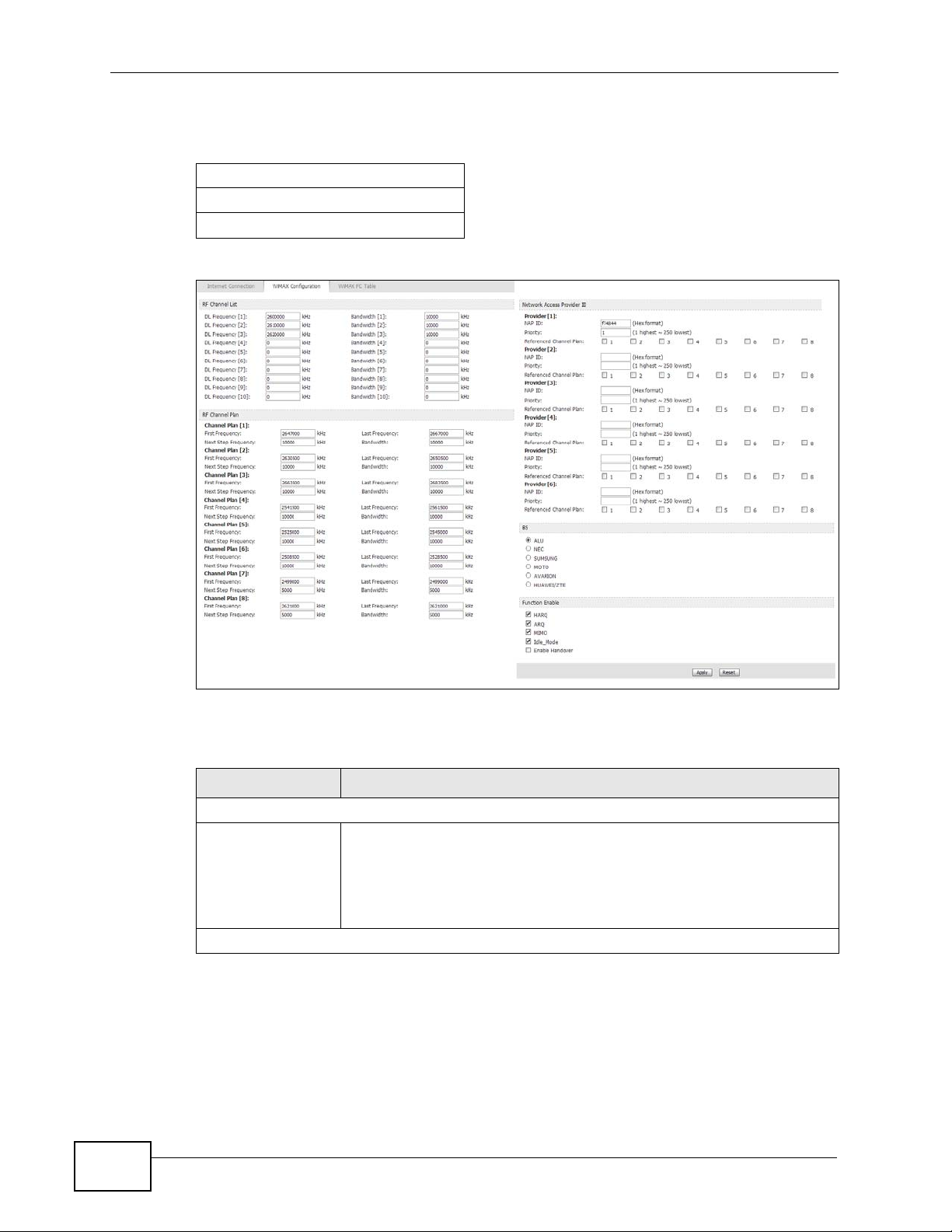
Chapter 7 The WAN Configuration Screens
Radio frequency is measured in Hertz (Hz).
Table 24 Radio Frequency Conversion
1 kHz = 1000 Hz
1 MHz = 1000 kHz (1000000 Hz)
1 GHz = 1000 MHz (1000000 kHz)
Figure 29 ADVANCED > WAN Configuration > WiMAX Configuration
76
The following table describes the labels in this screen.
Table 25 ADVANCED > WAN Configuration > WiMAX Configuration
LABEL DESCRIPTION
RF Channel List
DL Frequency /
Bandwidth
RF Channel Plan
These fields are the downlink frequency settings and bandwidth in
kilohertz (kHz). Enter values in these fields to have the MAX207HW2R scan these frequencies for available channels in ascending
numerical order.
Contact your service provider for details of supported frequencies.
MAX-207HW2R User’s Guide

Chapter 7 The WAN Configuration Screens
Table 25 ADVANCED > WAN Configuration > WiMAX Configuration (continued)
LABEL DESCRIPTION
First/Last/Next
Step Frequency &
Bandwidth
Network Access Provider ID
NAP ID Enter the primary network access provider ID for the WAN
Priority Enter the priority of the provider. You may set the priority from 1 to
Reference Channel
Plan
BS Select the base station to connect this MAX-207HW2R to.
Function Enable Select one or multiple check box(es) to enable the function(s).
These fields are the downlink frequency settings and bandwidth in
kilohertz (kHz).
In the First/Last Frequency fields, enter the range of frequency
for the MAX-207HW2R to scan for available channels
In the Next Step Frequency field, enter the value of the frequency
to scan each time that the MAX-207HW2R searches for a connection.
Contact your service provider for the bandwidth value and the
supported frequencies.
connection. You can also enter the substitude access provider IDs for
the connection backup when the primary one is down.
250.
Select which RF Channel Plan this provider is refering to.
Configure this according to what you were given by your service
provider.
• HARQ: Select this to enable the Hybrid Automatic RepeatRequest feature on the MAX-207HW2R. HARQ works in the
physical (PHY) layer and provides radio link error detection and
correction.
• ARQ: Select this to enable the Automatic Repeat-Request feature
on the MAX-207HW2R. ARQ works in the MAC layer and provides
error correction by scheduling re-transmission.
Both HARQ and ARQ are designed to provide reliable transmission
over a wireless connection. When a receiver detects errors, it will
notify the sender to retransmit the data within a certain period.
• MIMO: Select this to enable the Multple Input Multiple Ouput
(MIMO) feature on the MAX-207HW2R.
• Idle_Mode: Select this to have the MAX-207HW2R enter the idle
mode after it has no traffic passing through for a pre-defined
period. Make sure your base station also supports this before
selecting this.
• Enable Handover: Select this to maintain connectivity while the
MAX-207HW2R switch connection from one base station to
another base station.
Apply Click to save your changes.
Reset Click to restore your previously saved settings.
MAX-207HW2R User’s Guide
77

Chapter 7 The WAN Configuration Screens
7.3.1 Frequency Ranges
The following figure shows the MAX-207HW2R searching a range of frequencies to
find a connection to a base station.
Figure 30 Frequency Ranges
In this figure, A is the WiMAX frequency range. “WiMAX frequency r ange” refers to
the entire range of frequencies the MAX-207HW2R is capable of using to transmit
and receive (see the Product Specifications appendix for details).
In the figure, B shows the operator frequency range. This is the range of
frequencies within the WiMAX frequency range supported by your operator
(service provider).
The operator range is subdivided into bandwidth steps. In the figure, each C is a
bandwidth step.
The arrow D shows the MAX-207HW2R searching for a connection.
Have the MAX-207HW2R search only certain frequencies by configuring the
downlink frequencies. Your operator can give you information on the supported
frequencies.
The downlink frequencies are points of the frequency range your MAX-207HW2R
searches for an available connection. Use the Site Survey screen to set these
bands. You can set the downlink frequencies anywhere within the WiMAX
frequency range. In this example, the downlink frequencies have been set to
search all of the operator range for a connection.
7.3.2 Configuring Frequency Settings
78
You need to set the MAX-207HW2R to scan one or more specific radio frequencies
to find an available connection to a WiMAX base station.
Use the WiMAX Configuration screen to define the radio frequencies to be
searched for available wireless connections.
Note: It may take several minutes for the MAX-207HW2R to find a connection.
MAX-207HW2R User’s Guide

Chapter 7 The WAN Configuration Screens
• The MAX-207HW2R searches the DL Frequency settings in ascending
numerical order, from [1] to [10].
• If you enter a 0 in a DL Frequency field, the MAX-207HW2R immediately
moves on to the next DL Frequency field.
• When the MAX-207HW2R connects to a base station, the values in this screen
are automatically set to the base station’s frequency. The next time the MAX207HW2R searches for a connection, it searches only this frequency. If you want
the MAX-207HW2R to search other frequencies, enter them in the DL
Frequency fields.
The following table describes some examples of DL Frequency settings.
Table 26 DL Frequency Example Settings
EXAMPLE 1 EXAMPLE 2
DL Frequency
[1]:
DL Frequency
[2]:
DL Frequency
[3]:
DL Frequency
[4]:
2500000 2500000
2550000 2550000
0 2600000
00
The MAX-207HW2R
searches at 2500000
kHz, and then searches
at 2550000 kHz if it has
not found a connection.
The MAX-207HW2R
searches at 2500000 kHz
and then at 2550000 kHz if
it has not found an
available connection. If it
still does not find an
available connection, it
searches at 2600000 kHz.
MAX-207HW2R User’s Guide
79

Chapter 7 The WAN Configuration Screens
7.4 WiMAX FC Table
The MAX-207HW2R connects to a WiMAX base station (BS) for Internet access.
The WiMAX FC (Frequency Counter) T able screen is a read-only screen that shows
a list of the base stations information recently scanned by the MAX-207HW2R.
Figure 31 ADVANCED > WAN Configuration > WiMAX FC Table
The following table describes the labels in this screen.
Table 27 ADVANCED > WAN Configuration > WiMAX FC Table
LABEL DESCRIPTION
Most recently scanned WiMAX BS Table
Flush T able Select this check box to clear all the BS information in the WiMAX FC
Table.
BSID This field displays the identification number of the wireless base
station to which the MAX-207HW2R is connected. Every base station
transmits a unique BSID, which identifies it across the network.
Preamble ID This field displays the preamble id of the base station.
A preamble is an index identifier in the header of the base station’s
broadcast messages. In the beginning of a mobile station’s network
entry process, the mobile station searches the preamble and uses it
to get further channel characteristics information. It is used to
synchronize the upstream and downstream transmission timing with
the base station.
NAP ID This field displays the primary network access provider ID for the
WAN connection .
Frequency (KHz) This field shows the downlink frequency of the base station in
kilohertz (kHz).
80
MAX-207HW2R User’s Guide

Chapter 7 The WAN Configuration Screens
Table 27 ADVANCED > WAN Configuration > WiMAX FC Table (continued)
LABEL DESCRIPTION
Bandwidth (KHz) This field shows the bandwidth of the base station in kilohertz (kHz).
RSSI (dBm) This field shows the Received Signal Strength Indication. This value
is a measurement of overall radio signal strength. A higher RSSI
level indicates a stronger signal, and a lower RSSI level indicates a
weaker signal.
A strong signal does not necessarily indicate a good signal: a strong
signal may have a low signal-to-noise ratio (SNR).
CINR (dB) This field shows the average Carrier to Interference plus Noise Ratio
of the current connection. This value is an indication of overall radio
signal quality. A higher value indicates a higher signal quality, and a
lower value indicates a lower signal quality.
Apply Click to save your changes.
Reset Click to restore your previously saved settings.
MAX-207HW2R User’s Guide
81

Chapter 7 The WAN Configuration Screens
82
MAX-207HW2R User’s Guide

CHAPTER 8
The Port Configuration Screens
8.1 Overview
Use these screens to enable NAT and configure port forwarding for the MAX207HW2R.
Network Address Translation (NAT) maps a host’s IP address within one network
to a different IP address in another network. For example, you can use a NAT
router to map one IP address from your ISP to multiple private IP addresses for
the devices in your home network.
8.1.1 What You Can Do in This Chapter
•The General screen (Section 8.2 on page 84) lets you enable or disable NAT
and to allocate memory for NAT and firewall rules.
•The Port Forwarding screen (Section 8.3 on page 85) lets you look at the
current port-forwarding rules in the MAX-207HW2R, and to enable, disable,
activate, and deactivate each one.
MAX-207HW2R User’s Guide
83

Chapter 8 The Port Configuration Screens
8.2 General
Click ADVANCED > NA T Configuration > General to enable or d isable NAT and
to allocate memory for NAT and firewall rules.
Figure 32 ADVANCED > NAT Configuration > General
The following table describes the labels in this screen.
Table 28 ADVANCED > NAT Configuration > General
LABEL DESCRIPTION
Enable Network
Address Translation
Max NAT/Firewall
Session Per User
Apply
Reset Click to restore your previously saved settings.
Select this if you want to enable the Network Address Translation.
When computers use peer to peer applications, such as file sharing
applications, they may use a large number of NAT sessions. If yo u
do not limit the number of NAT sessions a single client can
establish, this can result in all of the available NAT sessions being
used. In this case, no additional NAT sessions can be established,
and users may not be able to access the Internet.
Each NAT session establishes a corresponding firew all session. Use
this field to limit the number of NAT/firewall sessions each client
computer can establish through the MAX-207HW2R.
If your network has a small number of clients using peer to peer
applications, you can raise this number to ensure that their
performance is not degraded by the number of NAT sessions they
can establish. If your network has a large number of users using
peer to peer applications, you can lower this number to ensure no
single client is using all of the available NAT sessions.
Click to save your changes.
84
MAX-207HW2R User’s Guide

8.3 Port Forwarding
A NAT server set is a list of inside (behind NAT on the LAN) servers, for example,
web or FTP, that you can make accessible to the outside world even though NAT
makes your whole inside network appear as a single machine to the outside world.
Use the ADVANCED > NAT Configuration > Port Forwarding screen to
forward incoming service requests to the server(s) on your local network. Y ou may
enter a single port number or a range of port numbers to be forwarded, and the
local IP address of the desired server. The port number identifies a service; for
example, web service is on port 80 and FTP on port 21. In some cases, such as for
unknown services or where one server can support more than one service (for
example both FTP and web service), it might be better to specify a range of port
numbers.
In addition to the servers for specified services, NAT supports a default server. A
service request that does not have a server explicitly designated for it is forwarded
to the default server. If the default is not defined, the service request is simply
discarded.
Chapter 8 The Port Configuration Screens
For example, let's say you want to assig n ports 21-25 to one FTP, Telnet and SMTP
server (A in the example), port 80 to another (B in the example) and assign a
default server IP address of 192.168.1.35 to a third (C in the example). You
assign the LAN IP addresses and the ISP assigns the WAN IP address. The NAT
network appears as a single host on the Internet.
Figure 33 Multiple Servers Behind NAT Example
8.3.1 Port Forwarding Options
Click ADVANCED > NAT Configuration > Port Forwarding to look at the
current port-forwarding rules in the MAX-207HW2R, and to enable, disable,
MAX-207HW2R User’s Guide
85

Chapter 8 The Port Configuration Screens
activate, and deactivate each one. You can also set up a default server to handle
ports not covered by rules.
Figure 34 ADVANCED > NAT Configuration > Port Forwarding
The following table describes the icons in this screen.
Table 29 ADVANCED > NAT Configuration > Port Forwarding
ICON DESCRIPTION
Edit
Click to edit this item.
Delete
Click to delete this item.
The following table describes the labels in this screen.
Table 30 ADVANCED > NAT Configuration > Port Forwarding
LABEL DESCRIPTION
Default Server Setup
Default Server Enter the IP address of the server to which the MAX-207HW2R should
forward packets for ports that are not specified in the Port Forwarding
section below or in the TOOLS > Remote MGMT screens. Enter
0.0.0.0 if you want the MAX-207HW2R to discard these packets instead.
Port Forwarding
#
Active
The number of the item in this list.
Select this to enable this rule. Clear this to disable this rule.
86
MAX-207HW2R User’s Guide

Table 30 ADVANCED > NAT Configuration > Port Forwarding (continued)
LABEL DESCRIPTION
Name This field displays the name of the rule. It does not have to be unique.
Start Port This field displays the beginning of the range of port numbers forwarded
by this rule.
End Port This field displays the end of the range of port numbers forwarded by
this rule. If it is the same as the Start Port, only one port number is
forwarded.
Server IP
Address
Action Click the Edit icon to set up a port forwarding rule or alter the
Apply
Reset Click to restore your previously saved settings.
This field displays the IP address of the server to which packet for the
selected port(s) are forwarded.
configuration of an existing port forwarding rule.
Click the Delete icon to remove an existing port forwarding rule.
Click to save your changes.
8.3.2 Port Forwarding Rule Setup
Chapter 8 The Port Configuration Screens
Click a port forwarding rule’s Edit icon in the ADVANCED > NAT Configuration
> Port Forwarding screen to activate, deactivate, or edit it.
Figure 35 ADVANCED > NAT Configuration > Port Forwarding > Rule Setup
The following table describes the labels in this screen.
Table 31 ADVANCED > NAT Configuration > Port Forwarding > Rule Setup
LABEL DESCRIPTION
Rule Se tup
Active
Service Name Enter a name to identify this rule. You can use 1 - 31 printable ASCII
Select this to enable this rule. Clear this to disable this rule.
characters, or you can leave this field blank. It does not have to be a
unique name.
MAX-207HW2R User’s Guide
87

Chapter 8 The Port Configuration Screens
Table 31 ADVANCED > NAT Configuration > Port Forwarding > Rule Setup
LABEL DESCRIPTION
Start Port
End Port
Server IP
Address
Apply Click to save your changes.
Cancel Click to return to the previous screen without saving your changes.
Enter the port number or range of port numbers you want to forward to
the specified server.
To forward one port number, enter the port number in the Start Port
and End Port fields.
To forward a range of ports,
• enter the port number at the beginning of the range in the Start
Port field
• enter the port number at the end of the range in the End Port field.
Enter the IP address of the server to which to forward packets for the
selected port number(s). This server is usually on the LAN.
88
MAX-207HW2R User’s Guide

CHAPTER 9
The System Configuration
Screens
9.1 Overview
Click ADVANCED > System Configuration to set up general system settings,
change the system mode, change the password, configure the DDNS server
settings, and set the current date and time.
9.1.1 What You Can Do in This Chapter
•The Dynamic DNS screen (Section 9.2 on page 90) lets you set up the MAX-
207HW2R as a dynamic DNS client.
•The Firmware screen (Section 9.3 on page 92) lets you upload new firmware to
the MAX-207HW2R.
•The Configuration screen (Section 9.4 on page 93) lets you back up or restore
the configuration of the MAX-207HW2R.
•The Restart screen (Section 9.5 on page 95) lets you restart your MAX-
207HW2R from within the web configurator.
9.1.2 What You Need to Know
The following terms and concepts may help as you read through this chapter.
System Name
The System Name is often used for identification purposes. Because some ISPs
check this name you should enter your computer's "Computer Name".
• In Windows 2000: Click Start > Settings > Control Panel and then doubleclick the System icon. Select the Network Identification tab and then click
the Properties button. Note the entry for the Computer Name field and enter
it as the System Name.
• In Windows XP: Click Start > My Computer > View system information and
then click the Computer Name tab. Note the entry in the Full computer
name field and enter it as the MAX-207HW2R System Name.
MAX-207HW2R User’s Guide
89

Chapter 9 The System Configuration Screens
Domain Name
The Domain Name entry is what is propagated to the DHCP clients on the LAN. If
you leave this blank, the domain name obtained by DHCP from the ISP is used.
While you must enter the host name (System Name) on each individual computer,
the domain name can be assigned from the MAX-207HW2R via DHCP.
DNS Server Address Assignment
Use DNS (Domain Name System) to map a domain name to its corresponding IP
address and vice versa, for instance, the IP address of www.zyxel.com is
204.217.0.2. The DNS server is extremely important because without it, you must
know the IP address of a computer before you can access it.
The MAX-207HW2R can get the DNS server addresses in the following ways:
1 The ISP tells you the DNS server addresses, usually in the form of an information
sheet, when you sign up. If your ISP g i ves you DNS server addresses, enter them
in the DNS Server fields in the SYSTEM General screen.
2 If the ISP did not give you DNS server information, leave the DNS Server fields in
the SYSTEM General screen set to 0.0.0.0 for the ISP to dynamically assign the
DNS server IP addresses.
9.2 Dynamic DNS
Dynamic DNS allows you to update your current dynamic IP address with one or
many dynamic DNS services so that anyone can contact you (in NetMeeting, CUSeeMe, etc.). You can also access your FTP server or Web site on your own
computer using a domain name (for instance myhost.dhs.org, where myhost is a
name of your choice) that will never change instead of using an IP address that
changes each time you reconnect. Your friends or relatives will always be able to
call you even if they don't know your IP address.
First of all, you need to have registered a dynamic DNS account with
www.dyndns.org. This is for people with a dynamic IP from their ISP or DHCP
server that would still like to have a domain name. The Dynamic DNS service
provider will give you a password or key.
90
Enabling the wildcard feature for your host causes *.yourhost.dyndns.org to be
aliased to the same IP address as yourhost.dyndns.org. This feature is useful if
you want to be able to use, for example, www.yourhost.dyndns. org and still reach
your hostname.
MAX-207HW2R User’s Guide

Chapter 9 The System Configuration Screens
Note: If you have a private WAN IP address, then you cannot use Dynamic DNS.
Click ADVANCED > System Configuration > Dynamic DNS to set up the MAX 207HW2R as a dynamic DNS client.
Figure 36 ADVANCED > System Configuration > Dynamic DNS
The following table describes the labels in this screen.
Table 32 ADVANCED > System Configuration > Dynamic DNS
LABEL DESCRIPTION
Dynamic DNS Setup
Enable Dynamic
DNS
Service
Provider
Dynamic DNS
Type
Host Name Enter the host name. You can specify up to two host names, separated
User Name Enter your user name.
Password
Enable Wildcard
Option
Enable offline
option (Only
applies to
custom DNS)
IP Address Update Policy
Use WAN IP
Address
Select this to use dynamic DNS.
Select the name of your Dynamic DNS service provider.
Select the type of service that you are registered for from your Dynamic
DNS service provider.
by a comma (",").
Enter the password assigned to you.
Select this to enable the DynDNS Wildcard feature.
This field is available when CustomDNS is selected in the DDNS Type
field. Select this if your Dynamic DNS service provider redirects traffic
to a URL that you can specify while you are off line. Check with your
Dynamic DNS service provider.
Select this if you want the MAX-207HW2R to update the domain name
with the WAN port's IP address.
MAX-207HW2R User’s Guide
91

Chapter 9 The System Configuration Screens
Table 32 ADVANCED > System Configuration > Dynamic DNS (continued)
LABEL DESCRIPTION
Dynamic DNS
server auto
detect IP
address
Select this if you want the DDNS server to update the IP address of the
host name(s) automatically. Select this option when there are one or
more NAT routers between the MAX-207HW2R and the DDNS server.
Note: The DDNS server may not be able to detect the proper IP
address if there is an HTTP proxy server between the MAX207HW2R and the DDNS server.
Use specified IP
address
Apply Click to save your changes.
Reset Click to restore your previously saved settings.
Select this if you want to use the specified IP address with the host
name(s). Then, specify the IP address. Use this option if you have a
static IP address.
9.3 Firmware
Click ADVANCED > System Configuration > Firmware to upload new
firmware to the MAX-207HW2R. Firmware files usually use the system model
name with a "*.bin" extension, such as "MAX-207HW2R.bin". The upload process
uses HTTP (Hypertext Transfer Protocol) and may take up to two minutes. After a
successful upload, the system will reboot.
Contact your service provider for information on available firmware upgrades.
Note: Only use firmware for your MAX-207HW2R’s specific model.
Figure 37 ADVANCED > System Configuration > Firmware
The following table describes the labels in this screen.
Table 33 ADVANCED > System Configuration > Firmware
LABEL DESCRIPTION
File Path Enter the location of the *.bin file you want to upload, or click
Browse... to find it. You must decompress compressed (.zip) files
before you can upload them.
92
MAX-207HW2R User’s Guide

Chapter 9 The System Configuration Screens
Table 33 ADVANCED > System Configuration > Firmware (continued)
LABEL DESCRIPTION
Browse... Click this to find the *.bin file you want to upload.
Upload Click this to begin uploading the selected file. This may take up to two
minutes.
Note: Do not turn off the device while firmware upload is in
progress!
9.3.1 The Firmware Upload Process
When the MAX-207HW2R uploads new firmware, the process usually takes about
two minutes. The device also automatically restarts in this time. This causes a
temporary network disconnect.
Note: Do not turn off the device while firmware upload is in progress!
After two minutes, log in again, and check your new firmware version in the
Status screen. You might have to open a new browser window to log in.
If the upload is not successful, you will be notified by error message.
Click Return to go back to the Firmware screen.
9.4 Configuration
Click ADVANCED > System Configuration > Configuration to back up or
restore the configuration of the MAX-207HW2R. You can also use this screen to
reset the MAX-207HW2R to the factory default settings.
Figure 38 ADVANCED > System Configuration > Configuration
MAX-207HW2R User’s Guide
93

Chapter 9 The System Configuration Screens
The following table describes the labels in this screen.
Table 34 ADVANCED > System Configuration > Configuration
LABEL DESCRIPTION
Backup Configuration
Backup Click this to save the MAX-207HW2R’s current configuration to a file on
your computer. Once your device is configured and functioning properly ,
it is highly recommended that you back up your configur ation file before
making configuration changes. The backup configuration file is useful if
you need to return to your previous settings.
Restore Configuration
File Path () Enter the location of the file you want to upload, or click Browse... to
find it.
Browse Click this to find the file you want to upload.
Upload Click this to restore the selected configuration file.
Note: Do not turn off the device while configuration file upload is in
progress.
Back to Factory Defaults
Reset Click this to clear all user-entered configuration information and return
the MAX-207HW2R to its factory defaults. There is no warning screen.
9.4.1 The Restore Configuration Process
When the MAX-207HW2R restores a configuration file, the device automatically
restarts. This causes a temporary network disconnect.
Note: Do not turn off the device while configuration file upload is in progress.
If the MAX-207HW2R’s IP address is different in the configuration file you
selected, you may need to change the IP address of your computer to be in the
same subnet as that of the default management IP address (192.168.5.1). See
the Quick Start Guide or the appendices for details on how to set up your
computer’s IP address.
You might have to open a new browser to log in again.
If the upload was not successful, you are notified by Configuration Upload Error
message:
Click Return to go back to the Configuration screen.
94
MAX-207HW2R User’s Guide

9.5 Restart
Click ADVANCED > System Configuration > Restart to reboot the MAX207HW2R without turning the power off.
Note: Restarting the MAX-207HW2R does not affect its configuration.
Figure 39 ADVANCED > System Configuration > Restart
The following table describes the labels in this screen.
Table 35 ADVANCED > System Configuration > Firmware
LABEL DESCRIPTION
Restart Click this button to have the device perform a software restart. The
Chapter 9 The System Configuration Screens
Power LED blinks as it restarts and the shines steadily if the restart is
successful.
Note: Wait one minute before log ging back into the MAX-207HW2R
after a restart.
9.5.1 The Restart Process
When you click Restart, the the process u su a lly takes ab out two minutes. Once
the restart is complete you can log in again.
MAX-207HW2R User’s Guide
95

Chapter 9 The System Configuration Screens
96
MAX-207HW2R User’s Guide

CHAPTER 10
The Service Configuration
Screens
10.1 Overview
The VOICE > Service Configuration screens allow you to set up your voice
accounts and configure your QoS settings.
VoIP (V oice over IP) is the sending of v oice signals over the Internet Protocol. This
allows you to make phone calls and send faxes over the Internet at a fraction of
the cost of using the traditional circuit-switched telephone network. You can also
use servers to run telephone service applications like PBX services and voice mail.
Internet Telephony Service Provider (ITSP) companies provid e VoIP service. A
company could alternatively set up an IP-PBX and provide it’s own VoIP service.
Circuit-switched telephone networks require 64 kilobits per second (kbps) in each
direction to handle a telephone call. VoIP can use advanced voice coding
techniques with compression to reduce the required bandwidth.
10.1.1 What You Can Do in This Chapter
•The SIP Setting screen (Section 10.2 on page 99) lets you setup and maintain
your SIP account(s) in the MAX -207HW2R.
•The Advanced SIP Settings screen (Section 10.2.1 on page 100) lets you set
up and maintain advanced settings for each SIP account
10.1.2 What You Need to Know
The following terms and concepts may help as you read through this chapter.
SIP
The Session Initiation Protocol (SIP) is an application-layer control (signaling)
protocol that handles the setting up, altering and tearing down of voice and
multimedia sessions over the Internet. SIP signaling is separate from the media
for which it handles sessions. The media that is exchanged during the session can
MAX-207HW2R User’s Guide
97

Chapter 10 The Service Configuration Scre en s
use a different path from that of the signaling. SIP handles telephone calls and can
interface with traditional circuit-switched telephone networks.
SIP Identities
A SIP account uses an identity (sometimes referred to as a SIP address). A
complete SIP identity is called a SIP URI (Uniform Resource Identifier). A SIP
account's URI identifies the SIP account in a way similar to the way an e-mail
address identifies an e-mail account. The format of a SIP identity is SIPNumber@SIP-Service-Domain.
SIP Number
The SIP number is the part of the SIP URI that comes before the “@” symbol. A
SIP number can use letters like in an e-mail address (johndoe@your-ITSP.com for
example) or numbers like a telephone number (1122334455@VoIP-provider.com
for example).
SIP Service Domain
The SIP service domain of the VoIP service provider (the company that lets you
make phone calls over the Internet) is the domain name in a SIP URI. For
example, if the SIP address is 1122334455@VoIP-provider.com
provider.com” is the SIP service domain.
, then “VoIP-
SIP Register Server
A SIP register server maintains a database of SIP identity-to-IP address (or
domain name) mapping. The register server checks your user name and password
when you register.
RTP
When you make a VoIP call using SIP, the RTP (Real time Transport Protocol) is
used to handle voice data transfer. See RFC 1889 for details on RTP.
Use NAT
If you know the NAT router’s public IP address and SIP port number, you can use
the Use NAT feature to manually configure the MAX-207HW2R to use a them in
the SIP messages. This eliminates the need for STUN or a SIP ALG. You must also
configure the NAT router to forward traffic with this port number to the MAX207HW2R.
98
MAX-207HW2R User’s Guide

10.1.3 Before you Begin
• Ensure that you have all of your voice account information on hand. If not,
contact your voice account service provider to find out which settings in this
chapter you should configure in order to use your telephone with the MAX207HW2R.
• Connect your MAX-207HW2R to the Internet, as described in the Quick Start
Guide. If you have not already done so, then you will not be able to test your
VoIP settings.
10.2 SIP Settings
Click VOICE > Service Configuration > SIP Setting to setup and maintain
your SIP account(s) in the MAX-207HW2R. Your VoIP or Internet service provider
should provide you with your account information. Y ou can als o enable and disable
each SIP account.
Chapter 10 The Service Configuration Screens
Figure 40 VOICE > Service Configuration > SIP Setting
The following table describes the labels in this screen.
Table 36 VOICE > Service Configuration > SIP Setting
LABEL DESCRIPTION
SIP Account Select the SIP account you want to see in this screen. If you change this
field, the screen automatically refreshes.
SIP Settings
Active SIP
Account
Phone
Number
Select this if you want the MAX-207HW2R to use this account. Clear it if
you do not want the MAX-207HW2R to use this account.
Enter your SIP number. In the full SIP URI, this is the part before the @
symbol. You can use up to 127 printable ASCII characters.
MAX-207HW2R User’s Guide
99

Chapter 10 The Service Configuration Scre en s
Table 36 VOICE > Service Configuration > SIP Setting (continued)
LABEL DESCRIPTION
SIP Local
Port
SIP Server
Address
SIP Server
Port
REGISTER
Server
Address
REGISTER
Server Port
SIP Service
Domain
Send Caller ID Select this if y ou want to send identification when you make VoIP phone
Authentication
User Name Enter the user name for registering this SIP account, exactly as it was
Password Enter the user name for registering this SIP account, exactly as it was
Show Advanced
Setup
Apply Click to save your changes.
Reset
Enter the MAX-207HW2R’s listening port number, if your VoIP service
provider gave you one. Otherwise, keep the default value.
Enter the IP address or domain name of the SIP server provided by
your VoIP service provider. You can use up to 95 printable ASCII
characters. It does not matter whether the SIP server is a proxy,
redirect or register server.
Enter the SIP server’s listening port number, if your VoIP service
provider gave you one. Otherwise, keep the default value.
Enter the IP address or domain name of the SIP register server, if your
VoIP service provider gave you one. Otherwise, enter the same address
you entered in the SIP Server Address field. You can use up to 95
printable ASCII characters.
Enter the SIP register server’s listening port number, if your VoIP
service provider gave you one. Otherwise, enter the same port number
you entered in the SIP Server Port field.
Enter the SIP service domain name. In the full SIP URI, this is the part
after the @ symbol. You can use up to 127 printable ASCII Extended
set characters.
calls. Clear this if you do not want to send identification.
given to you. You can use up to 95 printable ASCII characters.
given to you. You can use up to 95 printable ASCII Extended set
characters.
Click this to display the advanced settings for this SIP account in this
screen for editing.
Click to restore your previously saved settings.
10.2.1 Advanced SIP Settings
This section describes the features of the Advanced SIP settings screen.
10.2.1.1 Voice Coding
A codec (coder/decoder) codes analog voice signals into digital signals and
decodes the digital signals back into voice signals. The MAX-207HW2R supports
the following codecs.
100
MAX-207HW2R User’s Guide
 Loading...